EP1315134A1 - Antitheft device - Google Patents
Antitheft device Download PDFInfo
- Publication number
- EP1315134A1 EP1315134A1 EP01961230A EP01961230A EP1315134A1 EP 1315134 A1 EP1315134 A1 EP 1315134A1 EP 01961230 A EP01961230 A EP 01961230A EP 01961230 A EP01961230 A EP 01961230A EP 1315134 A1 EP1315134 A1 EP 1315134A1
- Authority
- EP
- European Patent Office
- Prior art keywords
- housing
- tag
- pin
- clamp member
- switch
- Prior art date
- Legal status (The legal status is an assumption and is not a legal conclusion. Google has not performed a legal analysis and makes no representation as to the accuracy of the status listed.)
- Granted
Links
Images



Classifications
-
- G—PHYSICS
- G08—SIGNALLING
- G08B—SIGNALLING SYSTEMS, e.g. PERSONAL CALLING SYSTEMS; ORDER TELEGRAPHS; ALARM SYSTEMS
- G08B13/00—Burglar, theft or intruder alarms
- G08B13/22—Electrical actuation
- G08B13/24—Electrical actuation by interference with electromagnetic field distribution
- G08B13/2402—Electronic Article Surveillance [EAS], i.e. systems using tags for detecting removal of a tagged item from a secure area, e.g. tags for detecting shoplifting
- G08B13/2428—Tag details
- G08B13/2434—Tag housing and attachment details
-
- E—FIXED CONSTRUCTIONS
- E05—LOCKS; KEYS; WINDOW OR DOOR FITTINGS; SAFES
- E05B—LOCKS; ACCESSORIES THEREFOR; HANDCUFFS
- E05B73/00—Devices for locking portable objects against unauthorised removal; Miscellaneous locking devices
- E05B73/0017—Anti-theft devices, e.g. tags or monitors, fixed to articles, e.g. clothes, and to be removed at the check-out of shops
-
- E—FIXED CONSTRUCTIONS
- E05—LOCKS; KEYS; WINDOW OR DOOR FITTINGS; SAFES
- E05B—LOCKS; ACCESSORIES THEREFOR; HANDCUFFS
- E05B73/00—Devices for locking portable objects against unauthorised removal; Miscellaneous locking devices
- E05B73/0017—Anti-theft devices, e.g. tags or monitors, fixed to articles, e.g. clothes, and to be removed at the check-out of shops
- E05B73/0047—Unlocking tools; Decouplers
- E05B73/0064—Unlocking tools; Decouplers of the mechanical type
-
- G—PHYSICS
- G08—SIGNALLING
- G08B—SIGNALLING SYSTEMS, e.g. PERSONAL CALLING SYSTEMS; ORDER TELEGRAPHS; ALARM SYSTEMS
- G08B13/00—Burglar, theft or intruder alarms
- G08B13/22—Electrical actuation
- G08B13/24—Electrical actuation by interference with electromagnetic field distribution
- G08B13/2402—Electronic Article Surveillance [EAS], i.e. systems using tags for detecting removal of a tagged item from a secure area, e.g. tags for detecting shoplifting
- G08B13/2428—Tag details
- G08B13/2448—Tag with at least dual detection means, e.g. combined inductive and ferromagnetic tags, dual frequencies within a single technology, tampering detection or signalling means on the tag
-
- Y—GENERAL TAGGING OF NEW TECHNOLOGICAL DEVELOPMENTS; GENERAL TAGGING OF CROSS-SECTIONAL TECHNOLOGIES SPANNING OVER SEVERAL SECTIONS OF THE IPC; TECHNICAL SUBJECTS COVERED BY FORMER USPC CROSS-REFERENCE ART COLLECTIONS [XRACs] AND DIGESTS
- Y10—TECHNICAL SUBJECTS COVERED BY FORMER USPC
- Y10T—TECHNICAL SUBJECTS COVERED BY FORMER US CLASSIFICATION
- Y10T70/00—Locks
- Y10T70/50—Special application
- Y10T70/5004—For antitheft signaling device on protected article
Definitions
- the present invention relates to antitheft devices for use as attached to commodities for preventing the commodity from being stolen, and more particularly to antitheft devices comprising a tag performing the function of preventing theft occurring upon escaping from a control area, and a member for attaching the tag to the commodity.
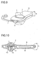
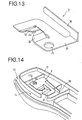
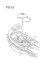
- FIGS. 9 to 15 show an antitheft device already proposed (Japanese Patent No. 2849048).
- the device comprises a tag 15 having a flat housing 16 composed of a lower half segment 17 and an upper half segment 18, and a member 2 for attaching the tag 15 to a garment or like commodity 9 as shown in FIG. 9.
- the housing 16 of the tag 15 has enclosed therein a sensor 40 which performs a specified theft preventing function when the tag 15 as affixed to the commodity is to be brought out of the store past a gate to actuate a theft alarm device installed in the gate.
- the attaching member 2 comprises a button 22 in the form of a disk, and a pin 21 projecting from the rear side of the button 22.
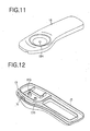
- a pinhole 18a is formed in the upper half segment 18 constituting the housing 16 for inserting therethrough the pin 21 of the attaching member 2 as shown in FIG. 11.
- the lower half segment 17 constituting the housing 16 is provided with a cylindrical portion 17a for the outer end of the pin 21 of the attaching member 2 to fit in (see FIG. 10).
- a spring clamp member 3 made of sheet metal is disposed inside the housing 16 of the tag 15.
- the spring clamp member 3 includes a main body 31 in the form of a flat plate and provided with a pair of clamp pieces 32, 32 for clamping the pin 21 of the attaching member 2 therebetween.
- the clamp pieces 32, 32 have outer end faces providing a clamp portion 34.
- the main body 31 has a circular hole 35 formed therein and a spring piece 36 projecting therefrom.
- the housing lower half segment 17 has a stepped cylindrical portion 17b positioned away from the cylindrical portion 17a.
- the spring clamp member 3 is rotatably supported on the housing lower half segment 17 by the stepped cylindrical portion 17b fitting in the circular hole 35 as seen in FIG. 14.
- the clamp member 3 has its spring piece 36 retained at the outer end thereof on the lower half segment 17 by engagement therewith.
- the spring piece 36 is elastically deformed by counterclockwise rotation of the main body 31, giving a clockwise repulsive force to the main body 31.
- a small opening 13 is formed in the housing 16 of the tag 15.
- the opening 13 communicates with the space wherein the clamp member 3 is installed through an inlet passage 14 formed in the housing lower half segment 17 as shown in FIG. 14.
- the pin 21 of the attaching member 2 is clamped by the spring clamp member 3 (see FIG. 10), whereby the attaching member 2 is prevented from being pulled out.
- the sensor 40 incorporated in the tag 15 receives a radio signal (e.g., lines of magnetic force) from the theft alarm device installed in the gate, and transmits a radio signal (e.g., altered magnetic field) to a theft preventing system in response to the received signal. Consequently, an alarm incorporated in the system is actuated, notifying salesclerks of the theft.
- a radio signal e.g., lines of magnetic force
- a radio signal e.g., altered magnetic field
- the forward end of the probe 7 is inserted into the clamp member accommodating space from the housing opening 13 through the inlet passage 14 to push the main body 31 of the clamp member 3 with the probe end against the elasticity of the spring piece 36.
- This rotates the clamp member 3 counterclockwise, thereby disengaging the clamp portion 34 of the clamp member 3 from the pin 21 of the attaching member 2 to unclamp the pin 21.
- the attaching member 2 can be removed.
- the antitheft device since the pin 21 of the attaching member 2 clamped by the clamp member 3 as shown in FIG. 10 can be cut at its base portion with a simple tool, the antitheft device has the problem of suffering an incident in that the tag 15 as attached to the commodity 9 is separated therefrom by cutting the pin 21 of the attaching member 2 to bring the commodity 9 only out of the store unlawfully.
- An object of the present invention is to provide an antitheft device which is capable of reliably preventing the foregoing wrongful act and which is nevertheless made compact.
- the present invention provides an antitheft device which comprises a tag 10 for performing a theft preventing function upon an escape from a specified control area, and an attaching member 2 for attaching the tag 10 to a commodity 9.
- the attaching member 2 comprises a button 22, and a pin 21 projecting from the button 22 and movable into a housing 1 of the tag 10 through a pinhole 12a formed in the housing 1.
- a clamp member 3 for clamping the pin 21 of the attaching member 2 as moved in through the pinhole 12a, an on-off switch 8 to be depressed by the button 22 of the attaching member 2, and a theft alarm operable under the control of on-off signals from the on-off switch 8.
- the clamp member 3 has a clamp portion 34 for the pin 21 of the attaching member 2 to be inserted therethrough for clamping the pin 21 unremovably.
- the clamp member 3 is rotatably supported by a pivot provided inside the housing 1, permits the clamp portion 34 to be disengaged from the pin 21 when rotated about the pivot in one direction and is given an elastic repulsive force against the rotation.
- the housing 1 is provided with an inlet passage 14 for an unclamping probe 7 for pushing the clamp member 3 into rotation toward the above-mentioned one direction.
- the on-off switch 8 comprises an actuator 82 having an outer end projecting outward from the housing 1 through a hole 12b formed in the housing 1, and a cylindrical guide . portion 83 formed around a base end portion of the actuator 82 and providing the pivot for the clamp member 3.
- the stepped cylindrical portion 17b provided in the conventional antitheft device for rotatably supporting the clamp member 3 thereon is omitted from the antitheft device of the present invention, while the on-off switch 8 is disposed at the corresponding position for the cylindrical guide portion 83 of the switch 8 to rotatably support the clamp member 3.
- the unclamping probe 7 is used for the salesclerk to remove the tag 10 from the commodity 9 as in the prior art. Stated more specifically, the forward end of the probe 7 is inserted into the space wherein the clamp member 3 is provided by way of the inlet passage 14 of the housing 1 to push the clamp member 3 with the forward end against the elastic repulsive force, whereby the clamp member 3 is rotated in the above-mentioned one direction to thereby disengage the clamp portion 34 from the pin 21 of the attaching member 2 and unclamp the pin 21. Consequently, the attaching member 2 becomes removable.
- the cylindrical guide portion 83 of the on-off switch 8 is utilized in the antitheft device of the invention in place of the stepped cylindrical portion 17b provided in the conventional antitheft device for rotatably supporting the clamp member 3.
- the additional provision of the on-off switch 8 is therefore unlikely to make the housing 1 greater in size. Accordingly, the present device remaining as large as the conventional antitheft device is adapted to reliably prevent the commodity 9 from being stolen by cutting the pin 21 of the attaching member 2.
- the antitheft device of the present invention is an improvement over the conventional antitheft device shown in FIGS. 9 to 15 (Japanese Patent No. 2849048) and is not different from the conventional device in the appearance shown in FIG. 9 and in the size of the device.
- Japanese Patent No. 28490408 Japanese Patent No. 28490478
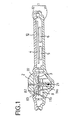
- a tag 10 has a housing 1, which comprises a lower half segment 11 and an upper half segment 12. Enclosed in the housing 1 are a circuit board 4 to perform a specified theft preventing function, a buzzer 6 to be actuated in the event of the unlawful act of cutting a pin 21 of an attaching member 2, and a cell 5 serving as a power source. Also disposed inside the housing 1 is an on-off switch 8 for detecting the unlawful act, if any, of cutting the pin 21 of the attaching member 2.
- the on-off switch 8 comprises a rectangular parallelepipedal body 81, a cylindrical guide portion 83 provided on the top of the body 81, and an actuator 82 to be guided for an upward or downward sliding movement by the guide portion 83.
- a pair of terminals 84, 84 are provided on a side wall of the body 81 for delivering the on or off signal to be produced upon a change-over between a depressed position (on position) and a released position (off position) of the actuator 82.
- the on or off signal output from the on-off switch 8 is fed to a drive circuit 41 on the circuit board 4.
- the drive circuit 41 drives the buzzer 6, notifying salesclerks of an unlawful act.
- the cell 5 supplies power to the drive circuit 41.
- the attaching member 2 comprises a button 22 in the form of a disk, and the pin 21 projecting from the rear side of the button 22.
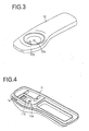
- the upper half segment 12 constituting the housing 1 is provided, in the region thereof where the attaching member 2 is to be installed, with a pinhole 12a for inserting the pin 21 of the attaching member 2 therethrough and a hole 12b for inserting the actuator 82 of the on-off switch 8 therethrough.
- the lower half segment 11 constituting the housing 1 is provided with a cylindrical portion 11a for the outer end of the pin 21 of the attaching member 2 to fit in, and a frame 11b for holding the body 81 of the on-off switch 8 therein (see FIG. 5).
- a spring clamp member 3 having the same construction as the conventional one is disposed inside the housing 1 of the tag 10.
- the clamp member 3 is rotatably supported on the housing lower half segment 11 by the cylindrical guide portion 83 of the switch 8 fitted in a circular hole 35 formed in the main body 31 of the clamp member 3 as seen in FIG. 6.
- the clamp member 3 has a spring piece 36 which is retained at its outer end on the lower half segment 11 by engagement therewith.
- the spring piece 36 is elastically deformed by counterclockwise rotation of the main body 31 to exert a clockwise repulsive force.
- the tag 10 If the tag 10 as attached to the commodity is to be brought out of the store past a gate, the tag 10 receives a radio signal (e.g., lines of magnetic force) from a theft alarm device installed in the gate, and transmits a radio signal (e.g., altered magnetic field) to a theft preventing system in response to the received signal. Consequently, an alarm incorporated in the system is actuated, notifying salesclerks of the occurrence of theft.
- a radio signal e.g., lines of magnetic force
- a radio signal e.g., altered magnetic field
- an unclamping probe 7 shown in FIG. 7 is used.
- the forward end of the probe 7 is inserted into the clamp member accommodating space from a housing opening 13 through an inlet passage 14 to push the main body 31 of the clamp member 3 with the probe end against the elasticity of the spring piece 36 as shown in the drawing.
- the attaching member 2 can be removed.
- the removal of the button 22 of the attaching member 2 from the tag 10 frees the actuator 82 of the on-off switch 8 from the depression by the button 22, projecting the actuator 82 from the depressed position to a released position to turn off the switch 8 which is closed.
- an on signal from the switch 8 is changed over to an off signal, which is fed to the drive circuit 41 to drive the buzzer 6, notifying salesclerks of the occurrence of theft.
- the signal is so processed as to hold the drive circuit out of operation when the attaching member 2 is removed by the salesclerk using the probe 7.
- the cylindrical guide portion 83 of the on-off switch 8 is utilized in the antitheft device of the invention in place of the stepped cylindrical portion 17b provided in the conventional antitheft device for rotatably supporting the clamp member 3.
- the additional provision of the on-off switch 8 is therefore unlikely to make the housing 1 greater in size. Accordingly, the present device remaining as large as the conventional antitheft device is adapted to reliably prevent the commodity from being stolen by cutting the pin 21 of the attaching member 2.
- the device of the present invention is not limited to the foregoing embodiment in construction but can be . modified variously without departing from the spirit of the invention as set forth in the appended claims.
- the theft preventing system installed in the gate is adapted to produce an alarm when the tag 10 as attached to a commodity 9 is moved past the gate according to the foregoing embodiment, whereas the buzzer 6 incorporated in the tag 10 can be actuated in response to a radio signal from the theft preventing system installed in the gate.
Landscapes
- Physics & Mathematics (AREA)
- Engineering & Computer Science (AREA)
- Automation & Control Theory (AREA)
- Computer Security & Cryptography (AREA)
- Electromagnetism (AREA)
- General Physics & Mathematics (AREA)
- Burglar Alarm Systems (AREA)
Abstract
Description
Throughout the drawings, like parts are designated by like reference numerals and will not be described repeatedly when so desired.
Claims (4)
- An antitheft device comprising a tag (10) for performing a theft preventing function upon an escape from a specified control area, and an attaching member (2) for attaching the tag (10) to a commodity (9), the attaching member (2) comprising a button (22), and a pin (21) projecting from the button (22) and movable into a housing (1) of the tag (10) through a pinhole (12a) formed in the housing (1), the tag housing (1) having arranged therein a clamp member (3) for clamping the pin (21) of the attaching member (2) as moved in through the pinhole (12a), an on-off switch (8) to be depressed by the button (22) of the attaching member (2), and a theft alarm operable under the control of on-off signals from the on-off switch (8), the clamp member (3) having a clamp portion (34) for the pin (21) of the attaching member (2) to be inserted therethrough for clamping the pin (21) unremovably, the clamp member (3) being rotatably supported by a pivot provided inside the housing (1), permitting the clamp portion (34) to be disengaged from the pin (21) when rotated in one direction and being given an elastic repulsive force against the rotation, the housing (1) being provided with an inlet passage (14) for an unclamping probe (7) for pushing the clamp member (3) into rotation toward said one direction, the on-off switch (8) comprising an actuator (82) having an outer end projecting outward from the housing (1) through a hole (12b) formed in the hosuing (1), and a cylindrical guide portion (83) formed around a base end portion of the actuator (82) and providing the pivot for the clamp member (3).
- An antitheft device according to claim 1 wherein the clamp member (3) has a circular hole (35) for the cylindrical guide porion (83) of the on-off switch (8) to fit in.
- An antitheft device according to claim 1 wherein the clamp member (3) is made of a sheet metal and has a spring piece (36) projecting therefrom and retained in the housing by engagement therewith to exhibit the elastic repulsive force.
- An antitheft device according to claim 1 wherein the theft alarm is provided by a buzzer (6) enclosed in the housing (1).
Applications Claiming Priority (4)
| Application Number | Priority Date | Filing Date | Title |
|---|---|---|---|
| JP2000626317 | 2000-08-31 | ||
| JP2000262317A JP4252713B2 (en) | 2000-08-31 | 2000-08-31 | Anti-theft device |
| JP2000262317 | 2000-08-31 | ||
| PCT/JP2001/007507 WO2002019292A1 (en) | 2000-08-31 | 2001-08-30 | Antitheft device |
Publications (4)
| Publication Number | Publication Date |
|---|---|
| EP1315134A1 true EP1315134A1 (en) | 2003-05-28 |
| EP1315134A8 EP1315134A8 (en) | 2003-11-19 |
| EP1315134A4 EP1315134A4 (en) | 2005-03-02 |
| EP1315134B1 EP1315134B1 (en) | 2008-02-13 |
Family
ID=18750014
Family Applications (1)
| Application Number | Title | Priority Date | Filing Date |
|---|---|---|---|
| EP01961230A Expired - Lifetime EP1315134B1 (en) | 2000-08-31 | 2001-08-30 | Antitheft device |
Country Status (9)
| Country | Link |
|---|---|
| US (1) | US6474117B2 (en) |
| EP (1) | EP1315134B1 (en) |
| JP (1) | JP4252713B2 (en) |
| CN (1) | CN1184598C (en) |
| AU (1) | AU2001282564A1 (en) |
| BR (1) | BR0113507A (en) |
| CA (1) | CA2420809C (en) |
| DE (1) | DE60132784T2 (en) |
| WO (1) | WO2002019292A1 (en) |
Families Citing this family (43)
| Publication number | Priority date | Publication date | Assignee | Title |
|---|---|---|---|---|
| US20020174695A1 (en) | 2001-05-25 | 2002-11-28 | David K. Huehner | Theft deterrent tag |
| DE10126288A1 (en) * | 2001-05-29 | 2003-01-02 | High Scan Artikelsicherungs Gm | Retail security device |
| US6801130B2 (en) * | 2002-10-11 | 2004-10-05 | Meadwestvaco Corporation | Inventory management system |
| US7347068B2 (en) * | 2003-03-06 | 2008-03-25 | Stuart Seidel | Anti-theft device |
| USD492214S1 (en) | 2003-04-07 | 2004-06-29 | Universal Surveillance Corporation | Electronic article surveillance device |
| US7190272B2 (en) * | 2003-05-06 | 2007-03-13 | Xiao Hui Yang | EAS tag with ball clutch |
| US7023348B2 (en) * | 2003-05-30 | 2006-04-04 | Sensormatic Electronics Corporation | Release techniques for a security tag |
| USD494487S1 (en) * | 2003-06-02 | 2004-08-17 | Adel O. Sayegh | Electronic article surveillance device with attachment |
| US7602299B2 (en) * | 2003-07-02 | 2009-10-13 | Sensormatic Electronics Corporation | Security tag having a linear clamp |
| US7148805B2 (en) * | 2003-08-08 | 2006-12-12 | Sensormatic Electronics Corporation | Hard security tag and detaching device |
| US7474215B2 (en) * | 2006-04-28 | 2009-01-06 | Checkpoint Systems, Inc. | Alarm systems, remote communication devices, and article security methods |
| US7400254B2 (en) | 2003-09-25 | 2008-07-15 | Xiao Hui Yang | EAS tag detachable by multiple methods |
| EP1704569B1 (en) * | 2003-12-10 | 2013-02-13 | Autronic Plastics, Inc. | Storage container with locking device for recorded media |
| JP4792560B2 (en) * | 2004-03-31 | 2011-10-12 | 株式会社サトーゴーセー | Information recording resin encapsulated tag |
| EP1784551A2 (en) * | 2004-08-19 | 2007-05-16 | Seidel Stuart | Anti-theft device |
| US7536884B2 (en) * | 2004-11-05 | 2009-05-26 | Sensormatic Electronics Corporation | Identification/surveillance device with removable tack button |
| US20060139176A1 (en) * | 2004-12-09 | 2006-06-29 | Johan Skjellerup | Security tag assembly |
| US20060145848A1 (en) * | 2004-12-28 | 2006-07-06 | Alpha Security Products, Inc. | Electronic security device and system for articles of merchandise |
| US8201425B2 (en) * | 2005-06-08 | 2012-06-19 | Autronic Plastics, Inc. | Hub lock for media disc storage container |
| US7737843B2 (en) * | 2005-12-23 | 2010-06-15 | Invue Security Products Inc. | Programmable alarm module and system for protecting merchandise |
| US7737846B2 (en) * | 2005-12-23 | 2010-06-15 | Invue Security Products Inc. | Security system and method for protecting merchandise |
| US20110254661A1 (en) | 2005-12-23 | 2011-10-20 | Invue Security Products Inc. | Programmable security system and method for protecting merchandise |
| US7737844B2 (en) * | 2005-12-23 | 2010-06-15 | Invue Security Products Inc. | Programming station for a security system for protecting merchandise |
| US7737845B2 (en) | 2005-12-23 | 2010-06-15 | Invue Security Products Inc. | Programmable key for a security system for protecting merchandise |
| US7598861B2 (en) * | 2006-01-06 | 2009-10-06 | Checkpoint Systems, Inc. | Security storage container having an internal alarm |
| US7663489B2 (en) * | 2006-04-28 | 2010-02-16 | Checkpoint Systems, Inc. | Alarm systems, wireless alarm devices, and article security methods |
| US7538680B2 (en) * | 2006-04-28 | 2009-05-26 | Checkpoint Systems, Inc. | Alarm systems, wireless alarm devices, and article security methods |
| US8125342B2 (en) * | 2007-11-23 | 2012-02-28 | Sensormatic Electronics, LLC | Electronic article surveillance tag |
| USD624447S1 (en) | 2009-02-24 | 2010-09-28 | Wg Security Products, Inc. | Electronic article surveillance tag |
| FR2955413B1 (en) * | 2010-01-19 | 2012-08-31 | Exaqtworld | ANTI-THEFT FLIGHT PROTECTION ASSEMBLY |
| US8631546B2 (en) * | 2010-09-07 | 2014-01-21 | Tyco Fire & Security Gmbh | Security system hard tag clamp and clamping method |
| USD649898S1 (en) | 2011-03-25 | 2011-12-06 | Wg Security Products | Low profile electronic article surveillance tag |
| US11017656B2 (en) | 2011-06-27 | 2021-05-25 | Invue Security Products Inc. | Programmable security system and method for protecting merchandise |
| FR2978186B1 (en) * | 2011-07-20 | 2015-10-23 | Exaqtworld | PROTECTION ASSEMBLY FOR THE THEFT OF A COMMERCIAL ARTICLE WITH TEMPORARY ASSEMBLY |
| USD697825S1 (en) | 2012-10-11 | 2014-01-21 | W G Security Products | Hanging anti-theft tag |
| CN107209977A (en) | 2014-11-18 | 2017-09-26 | Invue安全产品公司 | Key and safety device |
| US10121338B2 (en) | 2015-03-04 | 2018-11-06 | Tyco Fire & Security Gmbh | Self-detaching anti-theft device for retail environment |
| CN107924601B (en) * | 2015-06-12 | 2020-10-20 | 泰科消防及安全有限公司 | Self-dismantling anti-theft device with power removal station |
| CN106425987B (en) * | 2016-08-17 | 2018-07-20 | 宁波市北仑凯思诺电子科技厂 | A kind of multi-functional stripper |
| US10066422B2 (en) * | 2016-12-12 | 2018-09-04 | Xiao Hui Yang | EAS device with wrapping splitter for objects with wrapping |
| US9830792B1 (en) * | 2016-12-12 | 2017-11-28 | Xiao Hui Yang | EAS device with installation switch and activating base |
| USD904216S1 (en) | 2020-01-24 | 2020-12-08 | Control Group Companies Llc | Anti-theft ink tag |
| CN115731657B (en) * | 2022-10-15 | 2025-06-27 | 国家电网有限公司 | A transmission line anti-theft device |
Family Cites Families (16)
| Publication number | Priority date | Publication date | Assignee | Title |
|---|---|---|---|---|
| US3914829A (en) * | 1973-06-01 | 1975-10-28 | Eaton Corp | Releasably attachable clip |
| US3942829A (en) * | 1973-12-27 | 1976-03-09 | Sensormatic Electronics Corporation | Reusable security tag |
| US4012813A (en) * | 1974-10-30 | 1977-03-22 | I. D. Engineering, Inc. | Anti-theft fastening device and tool for releasing same |
| US4221025A (en) * | 1978-12-20 | 1980-09-09 | I. D. Engineering, Inc. | Anti-theft locking device |
| US4311992A (en) * | 1979-07-02 | 1982-01-19 | Eaton Corporation | Reusable releasable fastener |
| US4987754A (en) * | 1990-01-12 | 1991-01-29 | Knogo Corporation | Magnetically releasable target lock |
| CH684134A5 (en) * | 1991-12-16 | 1994-07-15 | Heinrich Sieber | On an object attachable safety trailer for signaling an attempted theft. |
| US5347262A (en) * | 1992-10-23 | 1994-09-13 | Security Tag Systems, Inc. | Theft-deterrent device providing force-sensitive tamper detection |
| US5426419A (en) * | 1993-01-14 | 1995-06-20 | Sensormatic Electronics Corporation | Security tag having arcuate channel and detacher apparatus for same |
| US5528914A (en) * | 1994-09-27 | 1996-06-25 | Sensormatic Electronics Corporation | Security tag and complemental deactivation apparatus |
| JPH08305969A (en) * | 1995-04-28 | 1996-11-22 | Sigma Kk | Anti-theft tag |
| US5852856A (en) * | 1997-11-13 | 1998-12-29 | Seidel; Stuart T. | Anti theft ink tag |
| JP3357831B2 (en) * | 1998-01-21 | 2002-12-16 | 三洋電機株式会社 | Article monitoring device |
| SE517454C2 (en) * | 1998-04-01 | 2002-06-11 | Faergklaemman Ab | Anti-theft device and locking elements and associated release device for an anti-theft device |
| US5955951A (en) * | 1998-04-24 | 1999-09-21 | Sensormatic Electronics Corporation | Combined article surveillance and product identification system |
| US6052876A (en) * | 1998-12-02 | 2000-04-25 | Sensormatic Electronics Corporation | Versatile attachment mechanism for theft deterrent tags |
-
2000
- 2000-08-31 JP JP2000262317A patent/JP4252713B2/en not_active Expired - Lifetime
-
2001
- 2001-08-13 US US09/927,370 patent/US6474117B2/en not_active Expired - Lifetime
- 2001-08-30 CA CA002420809A patent/CA2420809C/en not_active Expired - Lifetime
- 2001-08-30 CN CNB018149820A patent/CN1184598C/en not_active Expired - Lifetime
- 2001-08-30 DE DE60132784T patent/DE60132784T2/en not_active Expired - Lifetime
- 2001-08-30 BR BR0113507-4A patent/BR0113507A/en not_active Application Discontinuation
- 2001-08-30 AU AU2001282564A patent/AU2001282564A1/en not_active Abandoned
- 2001-08-30 WO PCT/JP2001/007507 patent/WO2002019292A1/en not_active Ceased
- 2001-08-30 EP EP01961230A patent/EP1315134B1/en not_active Expired - Lifetime
Also Published As
| Publication number | Publication date |
|---|---|
| EP1315134A8 (en) | 2003-11-19 |
| JP2002074527A (en) | 2002-03-15 |
| CA2420809C (en) | 2009-12-22 |
| JP4252713B2 (en) | 2009-04-08 |
| DE60132784T2 (en) | 2009-02-12 |
| WO2002019292A1 (en) | 2002-03-07 |
| CN1449550A (en) | 2003-10-15 |
| CN1184598C (en) | 2005-01-12 |
| EP1315134A4 (en) | 2005-03-02 |
| US6474117B2 (en) | 2002-11-05 |
| DE60132784D1 (en) | 2008-03-27 |
| EP1315134B1 (en) | 2008-02-13 |
| BR0113507A (en) | 2003-07-08 |
| US20020024440A1 (en) | 2002-02-28 |
| CA2420809A1 (en) | 2002-03-07 |
| AU2001282564A1 (en) | 2002-03-13 |
Similar Documents
| Publication | Publication Date | Title |
|---|---|---|
| US6474117B2 (en) | Antitheft device | |
| EP0658011B1 (en) | Electronic equipment with detachable control panel | |
| US5610376A (en) | Interlocking structure and detector for sensing the position of an operating member in detachable electronic equipment | |
| US5079540A (en) | Theft detection tag with adjustable loop | |
| JPH03201016A (en) | Handwriting input device | |
| JP2003051873A (en) | Mobile phone device holder and vehicle-mounted holder device | |
| US20030075931A1 (en) | Detachably connecting device | |
| US20250174095A1 (en) | Doorbell mounting and activation apparatus and method | |
| US5117210A (en) | Molded case circuit breaker field-installable accessories | |
| US5803323A (en) | Structure of carrying case for electronic equipment | |
| US5967570A (en) | Panel detaching apparatus for car-mounted audio system | |
| KR950019897A (en) | Method and apparatus for attaching or detaching a film strip to a film cartridge | |
| JP7500105B1 (en) | Punching section support device | |
| JP2003178387A (en) | Manual calling device | |
| US5359755A (en) | Garment security clip | |
| JP2776744B2 (en) | Anti-theft tag | |
| JP3754389B2 (en) | Anti-theft device | |
| JPH09202377A (en) | Soft storage case holder | |
| JP2517151Y2 (en) | Anti-theft device | |
| JP3480228B2 (en) | Anti-theft device for fixed articles | |
| JP3349039B2 (en) | Electronic cash register | |
| JP3525250B2 (en) | Gaming machine locking device | |
| JP3429153B2 (en) | Anti-theft device | |
| JP2005165594A (en) | Vending machine | |
| GB2140950A (en) | Warning devices |
Legal Events
| Date | Code | Title | Description |
|---|---|---|---|
| PUAI | Public reference made under article 153(3) epc to a published international application that has entered the european phase |
Free format text: ORIGINAL CODE: 0009012 |
|
| 17P | Request for examination filed |
Effective date: 20030228 |
|
| AK | Designated contracting states |
Designated state(s): AT BE CH CY DE DK ES FI FR GB GR IE IT LI LU MC NL PT SE TR |
|
| AX | Request for extension of the european patent |
Extension state: AL LT LV MK RO SI |
|
| RAP1 | Party data changed (applicant data changed or rights of an application transferred) |
Owner name: SENSORMATIC ELECTRONICS CORPORATION |
|
| RBV | Designated contracting states (corrected) |
Designated state(s): AT BE CH CY DE FR GB LI NL |
|
| A4 | Supplementary search report drawn up and despatched |
Effective date: 20050119 |
|
| GRAP | Despatch of communication of intention to grant a patent |
Free format text: ORIGINAL CODE: EPIDOSNIGR1 |
|
| GRAS | Grant fee paid |
Free format text: ORIGINAL CODE: EPIDOSNIGR3 |
|
| GRAA | (expected) grant |
Free format text: ORIGINAL CODE: 0009210 |
|
| AK | Designated contracting states |
Kind code of ref document: B1 Designated state(s): DE FR GB NL |
|
| RBV | Designated contracting states (corrected) |
Designated state(s): DE FR GB NL |
|
| REG | Reference to a national code |
Ref country code: GB Ref legal event code: FG4D |
|
| REF | Corresponds to: |
Ref document number: 60132784 Country of ref document: DE Date of ref document: 20080327 Kind code of ref document: P |
|
| ET | Fr: translation filed | ||
| PLBE | No opposition filed within time limit |
Free format text: ORIGINAL CODE: 0009261 |
|
| STAA | Information on the status of an ep patent application or granted ep patent |
Free format text: STATUS: NO OPPOSITION FILED WITHIN TIME LIMIT |
|
| 26N | No opposition filed |
Effective date: 20081114 |
|
| REG | Reference to a national code |
Ref country code: NL Ref legal event code: SD Effective date: 20111005 |
|
| REG | Reference to a national code |
Ref country code: FR Ref legal event code: TP Owner name: SENSORMATIC ELECTRONICS, LLC, US Effective date: 20110913 |
|
| REG | Reference to a national code |
Ref country code: GB Ref legal event code: 732E Free format text: REGISTERED BETWEEN 20150205 AND 20150211 |
|
| REG | Reference to a national code |
Ref country code: FR Ref legal event code: PLFP Year of fee payment: 15 |
|
| REG | Reference to a national code |
Ref country code: FR Ref legal event code: TP Owner name: TYCO FIRE & SECURITY GMBH, CH Effective date: 20160115 |
|
| REG | Reference to a national code |
Ref country code: FR Ref legal event code: PLFP Year of fee payment: 16 |
|
| REG | Reference to a national code |
Ref country code: FR Ref legal event code: PLFP Year of fee payment: 17 |
|
| REG | Reference to a national code |
Ref country code: FR Ref legal event code: PLFP Year of fee payment: 18 |
|
| REG | Reference to a national code |
Ref country code: GB Ref legal event code: 732E Free format text: REGISTERED BETWEEN 20191205 AND 20191211 |
|
| PGFP | Annual fee paid to national office [announced via postgrant information from national office to epo] |
Ref country code: NL Payment date: 20200826 Year of fee payment: 20 |
|
| PGFP | Annual fee paid to national office [announced via postgrant information from national office to epo] |
Ref country code: GB Payment date: 20200827 Year of fee payment: 20 Ref country code: FR Payment date: 20200825 Year of fee payment: 20 Ref country code: DE Payment date: 20200827 Year of fee payment: 20 |
|
| REG | Reference to a national code |
Ref country code: DE Ref legal event code: R071 Ref document number: 60132784 Country of ref document: DE |
|
| REG | Reference to a national code |
Ref country code: NL Ref legal event code: MK Effective date: 20210829 |
|
| REG | Reference to a national code |
Ref country code: GB Ref legal event code: PE20 Expiry date: 20210829 |
|
| PG25 | Lapsed in a contracting state [announced via postgrant information from national office to epo] |
Ref country code: GB Free format text: LAPSE BECAUSE OF EXPIRATION OF PROTECTION Effective date: 20210829 |