EP1314958A1 - Profiltiefe eines Reifens am fahrenden Fahrzeug mit einem Reifenabriebsverhältnis zweier Achsen - Google Patents
Profiltiefe eines Reifens am fahrenden Fahrzeug mit einem Reifenabriebsverhältnis zweier Achsen Download PDFInfo
- Publication number
- EP1314958A1 EP1314958A1 EP02020020A EP02020020A EP1314958A1 EP 1314958 A1 EP1314958 A1 EP 1314958A1 EP 02020020 A EP02020020 A EP 02020020A EP 02020020 A EP02020020 A EP 02020020A EP 1314958 A1 EP1314958 A1 EP 1314958A1
- Authority
- EP
- European Patent Office
- Prior art keywords
- tire
- depth
- profile depth
- tread
- determining
- Prior art date
- Legal status (The legal status is an assumption and is not a legal conclusion. Google has not performed a legal analysis and makes no representation as to the accuracy of the status listed.)
- Granted
Links
- 238000000034 method Methods 0.000 claims abstract description 28
- 238000005299 abrasion Methods 0.000 claims description 39
- 238000004364 calculation method Methods 0.000 claims description 11
- 230000007613 environmental effect Effects 0.000 claims description 8
- 238000012937 correction Methods 0.000 claims description 7
- 238000011156 evaluation Methods 0.000 claims description 4
- 238000013213 extrapolation Methods 0.000 claims description 4
- 238000005259 measurement Methods 0.000 claims description 4
- 230000000007 visual effect Effects 0.000 claims 3
- 230000015572 biosynthetic process Effects 0.000 claims 1
- 238000001514 detection method Methods 0.000 claims 1
- 230000003068 static effect Effects 0.000 claims 1
- 238000013500 data storage Methods 0.000 abstract 1
- 230000000694 effects Effects 0.000 description 3
- 230000001419 dependent effect Effects 0.000 description 2
- 238000010586 diagram Methods 0.000 description 2
- 238000012544 monitoring process Methods 0.000 description 2
- 238000007619 statistical method Methods 0.000 description 2
- 238000012935 Averaging Methods 0.000 description 1
- 230000001133 acceleration Effects 0.000 description 1
- 230000006870 function Effects 0.000 description 1
- 238000005096 rolling process Methods 0.000 description 1
- 238000012360 testing method Methods 0.000 description 1
Images


Classifications
-
- B—PERFORMING OPERATIONS; TRANSPORTING
- B60—VEHICLES IN GENERAL
- B60C—VEHICLE TYRES; TYRE INFLATION; TYRE CHANGING; CONNECTING VALVES TO INFLATABLE ELASTIC BODIES IN GENERAL; DEVICES OR ARRANGEMENTS RELATED TO TYRES
- B60C11/00—Tyre tread bands; Tread patterns; Anti-skid inserts
- B60C11/24—Wear-indicating arrangements
-
- G—PHYSICS
- G01—MEASURING; TESTING
- G01B—MEASURING LENGTH, THICKNESS OR SIMILAR LINEAR DIMENSIONS; MEASURING ANGLES; MEASURING AREAS; MEASURING IRREGULARITIES OF SURFACES OR CONTOURS
- G01B21/00—Measuring arrangements or details thereof, where the measuring technique is not covered by the other groups of this subclass, unspecified or not relevant
- G01B21/18—Measuring arrangements or details thereof, where the measuring technique is not covered by the other groups of this subclass, unspecified or not relevant for measuring depth
Definitions
- the invention relates to a method and a device for determining a profile depth a motor vehicle tire.
- a particular disadvantage here is that for determining the shape slip certain driving conditions required effort as well as for the evaluation of the Tire slip depending on the prevailing driving conditions. Another disadvantage is that for all types of tires approved for a vehicle Map to determine the tread depth from the evaluated tire slip Attempts must be determined.
- DE 32 36 520 C2 discloses a device for displaying the condition of tires known a vehicle, namely for monitoring the tires for one sudden drop in pressure. For this purpose, the speeds of the wheels are measured and with a Reference speed compared. The reference speed becomes too determined points in time that correspond to a predetermined driving condition. For The implementation of the monitoring will be different components of one anyway existing anti-lock braking system used. The profile depth is determined with the device known from this publication is not possible.
- DE 195 14 219 A1 describes a method for determining the tread depth of the tires Motor vehicle known, which is a continuous determination of the while driving Profile depth enables. It is based on a known profile depth of one new tire on the drive axle. This is the current tread depth of this tire determined in which a driving activity describing the driving style of the driver is determined, namely from the operating parameters of the vehicle such as throttle valve position, Engine speed, lateral acceleration, etc. Depending on the driving activity a specific tire wear is determined using a corresponding map. Knowing the initial tread depth will turn the specific tire wear into Dependence of the driving style as well as that since the determination of the initial profile depth distance covered determines the current profile depth. The tread depths of the wheels the front axle are based on the profile depth on the drive axle from the Wheel speed difference and driving speed determined from a map.
- a particular disadvantage here is that the driver's driving style is determined Descriptive driving activity from the operating parameters of the vehicle and relatively complex is inaccurate. The results of the wheel profile depth determination are corresponding unsatisfactory.
- the invention is therefore based on the object of an improved method and improved device for determining a tread depth of a motor vehicle tire create.
- the invention makes it possible to determine the tread depths of the tires of a motor vehicle by means of a tire abrasion ratio of tires on the first axis in relation to To determine tires on the second axis of the motor vehicle.
- the invention makes itself take advantage of the knowledge that a tire abrasion ratio is specific to the vehicle type can be determined which is characteristic of the vehicle type in question is.
- the tire abrasion ratio of a certain type of vehicle obtained through a statistical analysis.
- drives are carried out with vehicles of this type at that Ratio of tire wear of tires on the first axle, for example the rear axle, to determine the tires of the second axle, for example the front axle.
- the tire abrasion ratios determined in this way are, for example, in a histogram statistically evaluated. That tire abrasion ratio with the largest absolute Frequency or focus of the histogram is then considered to be the most relevant Defined tire abrasion ratio characterizing the vehicle type.
- front-wheel drives the tire abrasion ratio of tires on the rear axle to tires on the front axle in Generally between 0.3 to 0.9 and generally between 1.4 and for rear-wheel drive vehicles 2.4, with rear-wheel drive vehicles the tire abrasion ratio in general increases with increasing engine power.
- a known reference profile depth of one of the tires of the motor vehicle which as Reference tire is defined.
- the reference tire can be on the front or located on the rear axle. Furthermore, without restriction of generality assumed that the reference tire is on the rear axle.
- the current reference profile depth After a certain period of time determines the decrease in the tread depth of a tire on the front axle. By means of the Decrease in the tread depth of the tire on the front axle and the tire abrasion ratio the decrease in the tread depth of the reference tire is then determined, from which the current reference profile depth results.
- the determination the decrease in the tread depth of the tire on the front axle assumed that has not yet changed the given reference profile depth.
- the reference profile depth as the basis is then measured, for example, by Wheel speed ratios of wheels on the front and rear axles the tread depth of Wheels of the front axle determined. This then becomes the current one Reference profile depth determined. This procedure is repeated iteratively while driving of the motor vehicle.
- the Components of an anti-lock braking system control which is usually present anyway Implementation of a method according to the invention used.
- a usual Anti-lock braking system correction factors are determined for the control, which result from the Speed ratio of a tire under consideration to a reference tire. This Correction factors are used to determine the profile depth in an inventive Procedure used.
- the determined Profile depths to the driver of the motor vehicle, for example on a display in the Vehicle cockpit shown. Furthermore, the determined profile depths with a predetermined minimum profile depth are compared, if they are undershot for the Driver is given a warning signal.
- Extrapolation of the tire abrasion a distance still to be traveled to the minimum Tread depth is reached, determined and also displayed to the driver.
- appropriate sensors recorded environmental conditions of the vehicle, for. B. that Presence of road wetness, rain, tire slip as well as measuring the Outside temperature. These environmental conditions are then determined using the determined profile depth adjusted.
- a warning signal can be given Aquaplaning to be given to the driver. They are the same Traction characteristics on snow-covered roads are very different from that Depth of tire tread dependent. If the measured outside temperature and the May indicate the presence of tire slip on snow on the pavement this - with a correspondingly low profile depth - to output another appropriate warning to the driver.
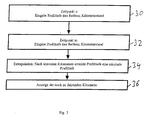
- FIG. 1 shows a flow diagram of a first embodiment of a inventive method for determining the profile depth.
- step 10 first defines a reference tire on an axle of the motor vehicle.
- any tire of the motor vehicle can be selected as a reference tire become. Without restricting generality, it is further assumed that that a tire on the rear axle of the vehicle is chosen as the reference tire.
- step 12 at least the tread depth of the reference tire is entered. This is preferably carried out when the vehicle is new tires.
- the profile depth of the new one The tire can then be found, for example, in a corresponding manufacturer's specification.
- the profile depth can also be entered at the factory.
- step 12 the tire wear ratio of tires on the rear axle entered for tires on the front axle of the vehicle.
- This is a vehicle type-specific parameter, the z. B. can be determined experimentally.
- the tire abrasion ratio can also be programmed in the factory, since it is a vehicle-specific constant.
- step 14 the decrease in the tread depth of tires on the front axle after determined for a certain period of time.
- the one entered in step 12 Reference profile depth can be used. This is considered to be essentially according to the length of time viewed unchanged.
- the rotational frequency ratios of a tire on the The front axle for the reference tire is the current from the reference tread depth Tread depth of the considered tire on the front axle. Such a measurement becomes too Beginning and end of the period carried out to decrease the depth of a profile Approximately determine the tire on the front axle. With this determination also include the driving speed, as per itself from DE 195 14 219 A1 is known.
- step 16 the current reference profile depth from the decrease in the profile depth of the considered wheels on the front axle determined by the given reference profile depth is reduced by the product of the decrease and the tire abrasion ratio. in the Furthermore, this process is repeated iteratively, in a subsequent step 14 the decrease in the tread depth of a wheel on the front axle is determined again, and again based on the reference profile depth. As a reference profile depth in the Step 14 becomes the current reference profile depth determined in the previous step 16 used, which in turn as approximately constant over the period of step 14 is faked.
- FIG. 2 shows a further preferred embodiment of the method according to the invention.
- the further tread depths of the tires of the motor vehicle can also be entered if they have a tread depth that deviates from the reference tread depth r ref , although this is not absolutely necessary.
- the tire wear ratio V of the axles i.e. H. the Ratio of tire wear of rear axle tires to tire wear of tires the front axle of the vehicle.
- the tire abrasion ratio V is type-specific and can be determined, for example, by a statistical analysis become.
- the rotational frequency f ref of the reference tire is determined while driving, and also the rotational frequency of the tire in question, the tread depth of which is to be determined, ie, for example, the rotational frequency f x of the left front tire.
- the tire wear on the right can be used to calculate factor F.
- Front wheel can be used. It is also possible that the tire wear on both Front wheels used approximately by arithmic averaging to determine the factor F. becomes.
- FIG. 3 shows a further preferred embodiment of the invention, which allows predict the remaining life of a tire.
- the profile depth can, for example, by means of a method according to FIG. 1 or FIG. 2 have been determined.
- the distance is then determined by extrapolation, after that by further tire abrasion a minimal profile depth has been reached.
- This remaining distance is in the Step 36 appears on a display for the driver. This has the particular advantage that the driver changes the tire sufficiently before reaching the minimum Can plan profile depth.
- FIG. 4 shows a vehicle 40 with a left rear tire 41, a left front tire 42, a right front tire 43 and a right rear tire 44.
- the left rear tire 41 is defined as a reference tire with a reference tread depth r ref
- the left front tire 42 has the tread depth r x
- the right front tire 43 has the tread depth ry
- the right rear tire 44 has the tread depth r z .
- the left rear tire 41 and the right rear tire 44 are on one
- the rear axle 45 and the left front tire 42 and the right front tire 43 are located on a front axle 46 of vehicle 40.
- Located on each wheel of vehicle 40 a sensor 47 for determining the rotational frequency of the wheel in question.
- Such sensors 47 are known per se for use in anti-lock braking systems.
- the sensors 47 feed their corresponding rotational frequency signals into a computer 48 on.
- the computer 48 can be part of the control of the anti-lock braking system of the vehicle 40 his.
- the computer 48 has a memory 49.
- the memory 49 can also be used for Storage of the tire abrasion ratio V serve.
- the computer 48 also has a program module 50.
- the program module 50 is used for Calculation of tire tread depths.
- the program module 50 can be stored 49 access to perform the necessary calculations. The corresponding calculations were explained in detail above with reference to FIG. 2.
- the profile depths currently determined by means of the program module 50 become after each Calculation stored in the memory 49 in order for a subsequent one Access to the update.
- the corresponding values of the profile depths are provided by a program module 51 evaluated. This is linked to a memory 52. There is one in the memory 52 Minimum profile depth for the safe operation of the vehicle 40 is stored.
- the program module 51 calculated from the decrease in the tread depth of a tire as a function of the mileage remaining by extrapolation.
- a program module 53 is provided, which the program module 50 determined profile depths with the minimum profile depth in the memory 52 and compares a warning signal is generated if the level is undershot. Furthermore, the program module 53 can also be designed to input further signals from sensors 54.
- the sensors can be used, for example, to monitor the road conditions serve, for example, with regard to rain or snow.
- the program module 53 can then adjust the minimum profile depth to the respective environmental situation, d. H. one at dry road surface still safe minimum tread depth can e.g. B. on wet roads reduced security. Likewise can be used for warning the driver Snow and other driving situations.
- the profile depths determined by the computer 48, the remaining term and, if appropriate Warnings generated by the program module 53 are shown on the display 55 for the Driver of vehicle 40 issued.
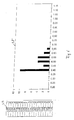
- FIG. 5 shows a histogram 56.
- the X axis of the histogram 56 shows that for one tire wear ratios measured for a particular vehicle type and the Y axis shows the absolute frequency for the different tire abrasion conditions.
- Table 57 shows the corresponding data: The left column of Table 57 shows the measured Tire abrasion ratios and the right column the number of vehicles of the same Type in which such a tire abrasion ratio was found.
- the histogram 56 has a pronounced maximum at the value 0.5 for the Tire abrasion ratio between tires on the rear axle and the front axle. This is defined as the type-specific constant tire abrasion ratio. Alternatively, you can also z. B. the focus of histogram 56 as the type specific Tire abrasion ratio can be viewed.
- FIG. 6 shows a representation corresponding to FIG. 5 for another Vehicle type.
- the corresponding histogram 58 there is a pronounced maximum at the tire abrasion ratio 0.4. This is called the type specific Tire abrasion ratio viewed.
- the corresponding statistically determined values, the Table 59 shows the basis of histogram 58.
- FIG. 7 shows the type-specific determined for different vehicle types Tire wear conditions.
- the tire abrasion ratio is generally in a range between 0.3 and 0.8 while with vehicles Rear-wheel drive is significantly above 1, with the tire abrasion ratio increasing Engine performance generally increases.
Landscapes
- Engineering & Computer Science (AREA)
- Mechanical Engineering (AREA)
- Physics & Mathematics (AREA)
- General Physics & Mathematics (AREA)
- Tires In General (AREA)
- Length Measuring Devices With Unspecified Measuring Means (AREA)
Abstract
Description
- Figur 1
- ein Flussdiagramm einer ersten Ausführungsform der Erfindung,
- Figur 2
- ein Flussdiagramm einer zweiten Ausführungsform der Erfindung,
- Figur 3
- ein Flussdiagramm einer dritten Ausführungsform der Erfindung zur Bestimmung der noch zu fahrenden Entfernung, bis eine minimale Profiltiefe erreicht ist,
- Figur 4
- ein Blockdiagramm einer erfindungsgemäßen Vorrichtung in einem Kraftfahrzeug,
- Figur 5
- ein Histogramm für die Ermittlung eines typspezifischen Reifenabriebsverhältnisses eines ersten Fahrzeugtyps,
- Figur 6
- ein Histogramm für die Ermittlung eines typspezifischen Reifenabriebsverhälntisses eines zweiten Fahrzeugtyps,
- Figur 7
- die unterschiedlichen Reifenabriebsverhältnisse verschiedener Fahrzeugtypen.
- Fahrzeug
- 40
- linker Hinterreifen
- 41
- linker Vorderreifen
- 42
- rechter Vorderreifen
- 43
- rechter Hinterreifen
- 44
- Hinterachse
- 45
- Vorderachse
- 46
- Sensor
- 47
- Rechner
- 48
- Speicher
- 49
- Programm-Modul
- 50
- Programm-Modul
- 51
- Speicher
- 52
- Programm-Modul
- 53
- Sensoren
- 54
- Anzeige
- 55
- Histogramm
- 56
- Tabelle
- 57
- Histogramm
- 58
Claims (23)
- Verfahren zur Ermittlung einer aktuellen Referenzprofiltiefe eines Referenzreifens an einer ersten Achse eines Kraftfahrzeugs basierend auf einer gegebenen Referenzprofiltiefe mit folgenden Schritten:Ermittlung der Abnahme einer Profiltiefe eines Reifens an einer zweiten Achse des Kraftfahrzeugs nach einer Zeitdauer mittels der gegebenen Referenzprofiltiefe,Ermittlung der aktuellen Referenzprofiltiefe aus der Abnahme und aus einem Reifenabriebsverhältnis von Reifen der ersten Achse und der zweiten Achse.
- Verfahren nach Anspruch 1 mit folgenden weiteren Schritten:Messung einer Referenzdrehfrequenz des Referenzreifens,Messung einer Drehfrequenz des Reifens an der zweiten Achse,Bildung eines Quotienten aus der Referenzdrehfrequenz und der Drehfrequenz,Multiplikation des Quotienten mit der Referenzprofiltiefe zur Ermittlung der Profiltiefe des Reifens.
- Verfahren nach Anspruch 2, bei dem die Ermittlung der Profiltiefe des Reifens zu Beginn und zum Ende der Zeitdauer für die Ermittlung der Abnahme erfolgt, wobei vorzugsweise für die Multiplikation des Quotienten die gegebene Referenzprofiltiefe verwendet wird.
- Verfahren nach einem der vorhergehenden Ansprüche 1, 2 oder 3, bei dem die ermittelte aktuelle Referenzprofiltiefe als gegebene Referenzprofiltiefe für eine nachfolgende Ermittlung einer weiteren aktuellen Referenzprofiltiefe verwendet wird.
- Verfahren nach einem der vorhergehenden Ansprüche 1 bis 4, bei dem die Ermittlung der aktuellen Referenzprofiltiefe auf der Grundlage der gegebenen Referenzprofiltiefe erfolgt, vorzugsweise der gegebenen Referenzprofiltiefe zu Beginn der Zeitdauer.
- Verfahren nach einem der vorhergehenden Ansprüche 1 bis 5, bei dem die aktuelle Referenzprofiltiefe durch Subtraktion des Produkts aus der Abnahme und des Reifenabriebsverhältnisses von der gegebenen Referenzprofiltiefe erfolgt.
- Verfahren nach einem der vorhergehenden Ansprüche 1 bis 6, bei demzu einem n-1 ten Zeitpunkt die gegebene Referenzprofiltiefe zur Berechnung der Profiltiefen von einem oder mehreren Reifen des Kraftfahrzeugs verwendet wird und die aktuelle Referenzprofiltiefe aus der gegebenen Referenzprofiltiefe unter Berücksichtigung der Abnahme der Profiltiefe eines Reifens an der zweiten Achse und dem Reifenabriebsverhältnis berechnet wird, undzu einem n-ten Zeitpunkt die aktuelle Referenzprofiltiefe des n1 ten Zeitpunkt als gegebene Referenzprofiltiefe für die Berechnung der Profiltiefen von einem oder mehreren Reifen des Kraftfahrzeugs verwendet wird.
- Verfahren nach einem der vorhergehenden Ansprüche 1 bis 7, wobei die Referenzprofiltiefe und / oder die Profiltiefen von einem oder mehreren weiteren Reifen des Kraftfahrzeugs für einen Fahrer des Kraftfahrzeugs angezeigt werden.
- Verfahren nach einem der vorhergehenden Ansprüche 1 bis 8, bei dem ein Vergleich mit einer minimalen Profiltiefe vorgenommen wird und ein visuelles, akustisches und / oder taktiles Warnsignal abgegeben wird, wenn eine ermittelte Profiltiefe die minimale Profiltiefe unterschreitet.
- Verfahren nach einem der vorhergehenden Ansprüche 1 bis 9 mit folgenden weiteren Schritten:Ermittlung der Abnahme einer Profiltiefe eines Reifens zwischen einem ersten Zeitpunkt (m) und einem zweiten Zeitpunkt (n),Ermittlung einer zwischen dem ersten und dem zweiten Zeitpunkt zurückgelegten Entfernung,Ermittlung einer noch zu fahrenden Entfernung durch Extrapolation der Abnahme der Profiltiefe bis auf eine minimale Profiltiefe,vorzugsweise visuelle Anzeige der verbleibenden zu fahrenden Entfernung.
- Verfahren nach einem der vorhergehenden Ansprüche 1 bis 10 mit folgenden weiteren Schritten:Ermittlung von Daten hinsichtlich einer Umweltbedingung, vorzugsweise hinsichtlich des Vorhandenseins von Straßennässe, Regen, Reifen-Schlupf und / oder der Außentemperatur,Auswertung der Daten hinsichtlich der Umweltbedingung basierend auf einer ermittelten Profiltiefe im Hinblick auf die Bewertung der Fahrsituation, vorzugsweise hinsichtlich Aquaplaning und / oder Schneetraktion.
- Verfahren nach einem der vorhergehenden Ansprüche 1 bis 11, wobei als Reifenabriebsverhältnis ein vom Typ des Kraftfahrzeugs abhängiger Parameter verwendet wird.
- Verfahren nach Anspruch 12, wobei der Parameter statistisch durch die Erfassung von Reifenabriebsverhältnissen einer statischen Menge von Kraftfahrzeugen desselben Typs ermittelt wird, z. B. als Maximum oder als Schwerpunkt eines entsprechenden Histogramms.
- Vorrichtung zur Ermittlung einer aktuellen Referenzprofiltiefe eines Referenzreifens (41) an einer ersten Achse (45) eines Kraftfahrzeugs (40) basierend auf einer gegebenen Referenzprofiltiefe (rref) mit:Mitteln (49, 50) zur Ermittlung einer Abnahme einer Profiltiefe eines Reifens (42, 43) an einer zweiten Achse (46) des Kraftfahrzeugs nach einer Zeitdauer mittels der gegebenen Referenzprofiltiefe,Mitteln (49, 50) zur Ermittlung der aktuellen Referenzprofiltiefe basierend auf der Abnahme und einem Reifenabriebsverhältnis von Reifen der ersten und der zweiten Achse.
- Vorrichtung nach Anspruch 14 mitMitteln (47) zur Messung einer Referenzdrehfrequenz des Referenzreifens,Mitteln (47) zur Messung einer Drehfrequenz des Reifens an der zweiten Achse,Mitteln (50) zur Bildung eines Quotienten aus der Referenzdrehfrequenz und der Drehfrequenz,Mitteln (50) zur Multiplikation des Quotienten mit der Referenzprofiltiefe zur Ermittlung der Profiltiefe des Reifens.
- Vorrichtung nach Anspruch 14 oder 15 mit einem Antiblockiersystem mit Mitteln zur Ermittlung einer Korrektur für die Antiblockiersystem-Regelung, wobei sich die Korrektur aus dem Quotienten der Drehfrequenz des Reifens an der zweiten Achse und der Referenzdrehfrequenz ergibt.
- Vorrichtung nach Anspruch 15 oder 16, bei der die Mittel zur Ermittlung der Profiltiefe des Reifens zur Ermittlung der Profiltiefe zu Beginn und zum Ende der Zeitdauer für die Ermittlung der Abnahme ausgebildet sind, wobei vorzugsweise für die Multiplikation des Quotienten die gegebene Referenzprofiltiefe verwendet wird.
- Vorrichtung nach einem der vorhergehenden Ansprüche 14 bis 17, mit einem Speicher für die Speicherung der für einen vorhergehenden Zeitpunkt bestimmten Profiltiefen.
- Vorrichtung nach Anspruch 18 mit einem Programm-Modul (50) zur Berechnung der Profiltiefen zu einem aktuellen Zeitpunkt, welches für die Berechnung der Profiltiefen auf den Speicher zugreift.
- Vorrichtung nach einem der vorhergehenden Ansprüche 14 bis 19 mit Mitteln (55) zur Anzeige der Referenzprofiltiefe und / oder der Profiltiefen von einem oder mehreren weiteren Reifen des Kraftfahrzeugs für einen Fahrer des Kraftfahrzeugs.
- Vorrichtung nach einem der vorhergehenden Ansprüche 14 bis 20 mit Mitteln (53) zum Vergleich einer ermittelten Profiltiefe mit einer minimalen Profiltiefe, wobei die Mittel zum Vergleich zur Abgabe eines visuellen akustischen und / oder taktilen Warnsignals ausgebildet sind, wenn eine ermittelte Profiltiefe die minimale Profiltiefe unterschreitet.
- Vorrichtung nach einem der vorhergehenden Ansprüche 14 bis 21 mitMitteln (51) zur Ermittlung der Abnahme einer Profiltiefe eines Reifens zwischen einem ersten Zeitpunkt (m) und einem zweiten Zeitpunkt (n),Mitteln (51) zur Ermittlung einer zwischen dem ersten und dem zweiten Zeitpunkt zurückgelegten Entfernung,Mitteln (51, 52) zur Ermittlung einer noch zu fahrenden Entfernung durch Extrapolation der Abnahme der Profiltiefe bis auf eine minimale Profiltiefe.
- Vorrichtung nach einem der vorhergehenden Ansprüche 14 bis 22 mitMitteln (54) zur Ermittlung von Daten hinsichtlich einer Umweltbedingung, vorzugsweise hinsichtlich des Vorhandenseins von Straßennässe, Regen, Reifen-Schlupf und / oder zur Messung der Außentemperatur,Mitteln (53) zur Auswertung der Daten hinsichtlich der Umweltbedingung und einer ermittelten Profiltiefe im Hinblick auf die Bewertung einer Fahrsituation, vorzugsweise hinsichtlich Aquaplaning und / oder Schneetraktion.
Applications Claiming Priority (2)
| Application Number | Priority Date | Filing Date | Title |
|---|---|---|---|
| DE10157261 | 2001-11-22 | ||
| DE2001157261 DE10157261B4 (de) | 2001-11-22 | 2001-11-22 | Verfahren und Vorrichtung zur Ermittlung einer Profiltiefe eines Kraftfahrzeugreifens |
Publications (2)
| Publication Number | Publication Date |
|---|---|
| EP1314958A1 true EP1314958A1 (de) | 2003-05-28 |
| EP1314958B1 EP1314958B1 (de) | 2005-09-21 |
Family
ID=7706547
Family Applications (1)
| Application Number | Title | Priority Date | Filing Date |
|---|---|---|---|
| EP20020020020 Expired - Lifetime EP1314958B1 (de) | 2001-11-22 | 2002-09-06 | Profiltiefe eines Reifens am fahrenden Fahrzeug mit einem Reifenabriebsverhältnis zweier Achsen |
Country Status (2)
| Country | Link |
|---|---|
| EP (1) | EP1314958B1 (de) |
| DE (2) | DE10157261B4 (de) |
Cited By (2)
| Publication number | Priority date | Publication date | Assignee | Title |
|---|---|---|---|---|
| DE102004016366A1 (de) * | 2004-03-31 | 2005-10-20 | Bayerische Motoren Werke Ag | Überwachungssystem hinsichtlich der an einem Kraftfahrzeug verbauten Fahrzeugreifen |
| WO2009080409A1 (en) * | 2007-12-19 | 2009-07-02 | Corghi S.P.A. | A method and a device for checking a vehicle efficiency |
Families Citing this family (2)
| Publication number | Priority date | Publication date | Assignee | Title |
|---|---|---|---|---|
| DE102020207789A1 (de) | 2020-06-23 | 2021-12-23 | Volkswagen Aktiengesellschaft | Verfahren, Computerprogramm und Vorrichtung zum Veranlassen eines Reifenwechsels für Reifen eines Kraftfahrzeugs |
| CN116278523B (zh) * | 2021-12-20 | 2025-11-11 | 固特异轮胎和橡胶公司 | 轮胎更换系统 |
Citations (2)
| Publication number | Priority date | Publication date | Assignee | Title |
|---|---|---|---|---|
| DE19514219A1 (de) * | 1995-04-15 | 1996-10-17 | Porsche Ag | Verfahren zur Ermittlung der Profiltiefe der Reifen eines Kraftfahrzeugs |
| EP0890458A2 (de) * | 1997-07-10 | 1999-01-13 | Sumitomo Rubber Industries Ltd. | Verschleisszustandserfassungsvorrichtung für Reifen und Verfahren |
Family Cites Families (3)
| Publication number | Priority date | Publication date | Assignee | Title |
|---|---|---|---|---|
| DE3236520A1 (de) * | 1982-10-02 | 1984-04-05 | Robert Bosch Gmbh, 7000 Stuttgart | Einrichtung zum anzeigen des zustandes von fahrzeugreifen |
| DE19619393B4 (de) * | 1995-07-26 | 2006-04-13 | Robert Bosch Gmbh | System zur Überwachung des Reifenzustandes |
| DE19831732A1 (de) * | 1998-07-15 | 2000-01-20 | Bayerische Motoren Werke Ag | Verfahren zur Bestimmung der Profiltiefe bei einem Fahrzeugreifen |
-
2001
- 2001-11-22 DE DE2001157261 patent/DE10157261B4/de not_active Expired - Fee Related
-
2002
- 2002-09-06 EP EP20020020020 patent/EP1314958B1/de not_active Expired - Lifetime
- 2002-09-06 DE DE50204315T patent/DE50204315D1/de not_active Expired - Lifetime
Patent Citations (2)
| Publication number | Priority date | Publication date | Assignee | Title |
|---|---|---|---|---|
| DE19514219A1 (de) * | 1995-04-15 | 1996-10-17 | Porsche Ag | Verfahren zur Ermittlung der Profiltiefe der Reifen eines Kraftfahrzeugs |
| EP0890458A2 (de) * | 1997-07-10 | 1999-01-13 | Sumitomo Rubber Industries Ltd. | Verschleisszustandserfassungsvorrichtung für Reifen und Verfahren |
Cited By (3)
| Publication number | Priority date | Publication date | Assignee | Title |
|---|---|---|---|---|
| DE102004016366A1 (de) * | 2004-03-31 | 2005-10-20 | Bayerische Motoren Werke Ag | Überwachungssystem hinsichtlich der an einem Kraftfahrzeug verbauten Fahrzeugreifen |
| DE102004016366B4 (de) * | 2004-03-31 | 2012-02-23 | Bayerische Motoren Werke Aktiengesellschaft | Überwachungssystem hinsichtlich der an einem Kraftfahrzeug verbauten Fahrzeugreifen |
| WO2009080409A1 (en) * | 2007-12-19 | 2009-07-02 | Corghi S.P.A. | A method and a device for checking a vehicle efficiency |
Also Published As
| Publication number | Publication date |
|---|---|
| DE50204315D1 (de) | 2006-02-02 |
| EP1314958B1 (de) | 2005-09-21 |
| DE10157261A1 (de) | 2003-06-12 |
| DE10157261B4 (de) | 2007-05-03 |
Similar Documents
| Publication | Publication Date | Title |
|---|---|---|
| DE69817698T2 (de) | Verschleisszustandserfassungsvorrichtung für Reifen und Verfahren | |
| EP1826530B1 (de) | Verfahren und Vorrichtung zur Umfangsermittlung eines Rades | |
| DE102012217901B3 (de) | Verfahren, Steuergerät und System zum Ermitteln einer Profiltiefe eines Profils eines Reifens | |
| DE69705549T2 (de) | Verfahren und Vorrichtung zur Identifikation der Art des Reifens | |
| EP2170631B1 (de) | Verfahren und vorrichtung zur reifenzustandsüberwachung | |
| DE102016203545B4 (de) | Verfahren zur Bestimmung von Fahrbahngriffigkeitsklassen | |
| EP3027435B1 (de) | Verfahren und system zur bestimmung einer druckabweichung zwischen einem sollreifendruck und einem aktuellen reifendruck für einen reifen eines fahrzeugs sowie zur bestimmung einer radlast | |
| DE19803386A1 (de) | Vorrichtung zur Überwachung des Luftdrucks eines Fahrzeugreifens | |
| DE202018006904U1 (de) | System zur modellbasierten Reifenverschleißschätzung | |
| DE102004019320A1 (de) | System zum Reproduzieren des dynamischen Verhaltens eines Fahrzeugs | |
| DE69729250T2 (de) | Gerät zur feststellung eines druckverlustes in einem reifen | |
| DE19746431A1 (de) | Reifenunterdruckwarnsystem | |
| DE102013220882B4 (de) | Verfahren, Steuergerät und System zum Ermitteln einer Profiltiefe eines Profils zumindest eines Reifens | |
| EP0938987A2 (de) | Verfahren und Vorrichtung zur Überwachung des Reifenluftdrucks von Rädern eines Kraftfahrzeuges | |
| WO2004083012A1 (de) | Verfahren und vorrichtung zur ermittlung einer den zwischen fahrbahn und fahrzeugreifen vorliegenden reibwert repräsentierenden reibwertgrösse | |
| DE10024178A1 (de) | Verfahren zur verbesserten Bestimmung des Verhältnisses der Radien der Räder eines Fahrzeuges zueinander | |
| DE69715134T2 (de) | Verfahren und Ausrüstung zum Erkennen eines Reifens mit zumindest teilweisem Druckverlust an einem Kraftfahtzeug. | |
| DE102006053826A1 (de) | Verfahren zur indirekten Reifendrucküberwachung | |
| DE10157885A1 (de) | Verfahren und Vorrichtung zur Bestimmung des Reifenluftdrucks | |
| EP1951534B1 (de) | Verfahren zur erkennung der beladung eines kraftfahrzeugs | |
| EP1575790B1 (de) | Verfahren zur indirekten druckverlusterkennung an einem kraftfahrzeugrad | |
| DE10157261B4 (de) | Verfahren und Vorrichtung zur Ermittlung einer Profiltiefe eines Kraftfahrzeugreifens | |
| DE19523917C2 (de) | Verfahren und Vorrichtung zum Bestimmen der Profiltiefe von Fahrzeugreifen | |
| WO2001044001A1 (de) | Verfahren und vorrichtung zur erkennung eines druckverlustes von reifen in kraftfahrzeugen | |
| EP1240038B1 (de) | Verfahren und vorrichtung zur erkennung eines druckverlustes von reifen in kraftfahrzeugen |
Legal Events
| Date | Code | Title | Description |
|---|---|---|---|
| PUAI | Public reference made under article 153(3) epc to a published international application that has entered the european phase |
Free format text: ORIGINAL CODE: 0009012 |
|
| AK | Designated contracting states |
Designated state(s): AT BE BG CH CY CZ DE DK EE ES FI FR GB GR IE IT LI LU MC NL PT SE SK TR |
|
| AX | Request for extension of the european patent |
Extension state: AL LT LV MK RO SI |
|
| 17P | Request for examination filed |
Effective date: 20031128 |
|
| AKX | Designation fees paid |
Designated state(s): DE FR GB IT |
|
| 17Q | First examination report despatched |
Effective date: 20041027 |
|
| GRAP | Despatch of communication of intention to grant a patent |
Free format text: ORIGINAL CODE: EPIDOSNIGR1 |
|
| GRAS | Grant fee paid |
Free format text: ORIGINAL CODE: EPIDOSNIGR3 |
|
| GRAA | (expected) grant |
Free format text: ORIGINAL CODE: 0009210 |
|
| AK | Designated contracting states |
Kind code of ref document: B1 Designated state(s): DE FR GB IT |
|
| PG25 | Lapsed in a contracting state [announced via postgrant information from national office to epo] |
Ref country code: IT Free format text: LAPSE BECAUSE OF FAILURE TO SUBMIT A TRANSLATION OF THE DESCRIPTION OR TO PAY THE FEE WITHIN THE PRESCRIBED TIME-LIMIT;WARNING: LAPSES OF ITALIAN PATENTS WITH EFFECTIVE DATE BEFORE 2007 MAY HAVE OCCURRED AT ANY TIME BEFORE 2007. THE CORRECT EFFECTIVE DATE MAY BE DIFFERENT FROM THE ONE RECORDED. Effective date: 20050921 Ref country code: GB Free format text: LAPSE BECAUSE OF FAILURE TO SUBMIT A TRANSLATION OF THE DESCRIPTION OR TO PAY THE FEE WITHIN THE PRESCRIBED TIME-LIMIT Effective date: 20050921 |
|
| REG | Reference to a national code |
Ref country code: GB Ref legal event code: FG4D Free format text: NOT ENGLISH |
|
| REF | Corresponds to: |
Ref document number: 50204315 Country of ref document: DE Date of ref document: 20051027 Kind code of ref document: P |
|
| REF | Corresponds to: |
Ref document number: 50204315 Country of ref document: DE Date of ref document: 20060202 Kind code of ref document: P |
|
| GBV | Gb: ep patent (uk) treated as always having been void in accordance with gb section 77(7)/1977 [no translation filed] |
Effective date: 20050921 |
|
| PLBE | No opposition filed within time limit |
Free format text: ORIGINAL CODE: 0009261 |
|
| STAA | Information on the status of an ep patent application or granted ep patent |
Free format text: STATUS: NO OPPOSITION FILED WITHIN TIME LIMIT |
|
| 26N | No opposition filed |
Effective date: 20060622 |
|
| PG25 | Lapsed in a contracting state [announced via postgrant information from national office to epo] |
Ref country code: FR Free format text: LAPSE BECAUSE OF FAILURE TO SUBMIT A TRANSLATION OF THE DESCRIPTION OR TO PAY THE FEE WITHIN THE PRESCRIBED TIME-LIMIT Effective date: 20061020 |
|
| EN | Fr: translation not filed | ||
| PG25 | Lapsed in a contracting state [announced via postgrant information from national office to epo] |
Ref country code: FR Free format text: LAPSE BECAUSE OF FAILURE TO SUBMIT A TRANSLATION OF THE DESCRIPTION OR TO PAY THE FEE WITHIN THE PRESCRIBED TIME-LIMIT Effective date: 20050921 |
|
| PGFP | Annual fee paid to national office [announced via postgrant information from national office to epo] |
Ref country code: DE Payment date: 20190930 Year of fee payment: 18 |
|
| REG | Reference to a national code |
Ref country code: DE Ref legal event code: R119 Ref document number: 50204315 Country of ref document: DE |
|
| PG25 | Lapsed in a contracting state [announced via postgrant information from national office to epo] |
Ref country code: DE Free format text: LAPSE BECAUSE OF NON-PAYMENT OF DUE FEES Effective date: 20210401 |