EP1314894B2 - Fan - Google Patents
Fan Download PDFInfo
- Publication number
- EP1314894B2 EP1314894B2 EP02023117A EP02023117A EP1314894B2 EP 1314894 B2 EP1314894 B2 EP 1314894B2 EP 02023117 A EP02023117 A EP 02023117A EP 02023117 A EP02023117 A EP 02023117A EP 1314894 B2 EP1314894 B2 EP 1314894B2
- Authority
- EP
- European Patent Office
- Prior art keywords
- signal
- equipment fan
- drive motor
- fan according
- housing
- Prior art date
- Legal status (The legal status is an assumption and is not a legal conclusion. Google has not performed a legal analysis and makes no representation as to the accuracy of the status listed.)
- Expired - Lifetime
Links
- 230000001419 dependent effect Effects 0.000 claims abstract description 12
- 239000003990 capacitor Substances 0.000 claims description 16
- 230000001681 protective effect Effects 0.000 claims description 15
- 238000004804 winding Methods 0.000 claims description 9
- 238000009499 grossing Methods 0.000 claims description 5
- 230000004913 activation Effects 0.000 claims 2
- 238000000034 method Methods 0.000 claims 1
- 230000000903 blocking effect Effects 0.000 description 3
- 230000002441 reversible effect Effects 0.000 description 3
- 230000007423 decrease Effects 0.000 description 2
- 238000012986 modification Methods 0.000 description 2
- 230000004048 modification Effects 0.000 description 2
- 238000012544 monitoring process Methods 0.000 description 2
- 230000000737 periodic effect Effects 0.000 description 2
- 230000002829 reductive effect Effects 0.000 description 2
- 230000001960 triggered effect Effects 0.000 description 2
- 230000009471 action Effects 0.000 description 1
- 230000008901 benefit Effects 0.000 description 1
- 230000002457 bidirectional effect Effects 0.000 description 1
- 230000006835 compression Effects 0.000 description 1
- 238000007906 compression Methods 0.000 description 1
- 230000003247 decreasing effect Effects 0.000 description 1
- 230000007547 defect Effects 0.000 description 1
- 230000002950 deficient Effects 0.000 description 1
- 238000003745 diagnosis Methods 0.000 description 1
- 238000010586 diagram Methods 0.000 description 1
- 230000000694 effects Effects 0.000 description 1
- 230000005294 ferromagnetic effect Effects 0.000 description 1
- 238000007689 inspection Methods 0.000 description 1
- 238000009434 installation Methods 0.000 description 1
- 230000000670 limiting effect Effects 0.000 description 1
- 230000005291 magnetic effect Effects 0.000 description 1
- 230000001172 regenerating effect Effects 0.000 description 1
- 230000008439 repair process Effects 0.000 description 1
- 125000006850 spacer group Chemical group 0.000 description 1
- 238000011179 visual inspection Methods 0.000 description 1
Images


Classifications
-
- F—MECHANICAL ENGINEERING; LIGHTING; HEATING; WEAPONS; BLASTING
- F04—POSITIVE - DISPLACEMENT MACHINES FOR LIQUIDS; PUMPS FOR LIQUIDS OR ELASTIC FLUIDS
- F04D—NON-POSITIVE-DISPLACEMENT PUMPS
- F04D25/00—Pumping installations or systems
- F04D25/02—Units comprising pumps and their driving means
- F04D25/06—Units comprising pumps and their driving means the pump being electrically driven
- F04D25/0606—Units comprising pumps and their driving means the pump being electrically driven the electric motor being specially adapted for integration in the pump
- F04D25/0613—Units comprising pumps and their driving means the pump being electrically driven the electric motor being specially adapted for integration in the pump the electric motor being of the inside-out type, i.e. the rotor is arranged radially outside a central stator
-
- F—MECHANICAL ENGINEERING; LIGHTING; HEATING; WEAPONS; BLASTING
- F04—POSITIVE - DISPLACEMENT MACHINES FOR LIQUIDS; PUMPS FOR LIQUIDS OR ELASTIC FLUIDS
- F04D—NON-POSITIVE-DISPLACEMENT PUMPS
- F04D29/00—Details, component parts, or accessories
- F04D29/60—Mounting; Assembling; Disassembling
- F04D29/601—Mounting; Assembling; Disassembling specially adapted for elastic fluid pumps
-
- Y—GENERAL TAGGING OF NEW TECHNOLOGICAL DEVELOPMENTS; GENERAL TAGGING OF CROSS-SECTIONAL TECHNOLOGIES SPANNING OVER SEVERAL SECTIONS OF THE IPC; TECHNICAL SUBJECTS COVERED BY FORMER USPC CROSS-REFERENCE ART COLLECTIONS [XRACs] AND DIGESTS
- Y10—TECHNICAL SUBJECTS COVERED BY FORMER USPC
- Y10S—TECHNICAL SUBJECTS COVERED BY FORMER USPC CROSS-REFERENCE ART COLLECTIONS [XRACs] AND DIGESTS
- Y10S388/00—Electricity: motor control systems
- Y10S388/90—Specific system operational feature
- Y10S388/903—Protective, e.g. voltage or current limit
Abstract
Description
Die Erfindung betrifft einen Gerätelüfter mit einem Antriebsmotor. Bevorzugt betrifft die Erfindung einen derartigen Lüfter, der über eine Steuerleitung ("Bus") mit einem externen Steuergerät kommunizieren kann.The invention relates to a device fan with a drive motor. Preferably, the invention relates to such a fan, which can communicate via a control line ("bus") with an external control device.
Aus der
Aus der
Als nächstliegender Stand der Technik betrifft die
Es ist eine Aufgabe der Erfindung, einen neuen Gerätelüfter bereit zu stellen.It is an object of the invention to provide a new equipment fan.
Nach der Erfindung wird diese Aufgabe gelöst durch einen Gerätelüfter nach Anspruch 1. Ein solcher Gerätelüfter ermöglicht einen sehr einfachen Einbau, da zusätzlich zur Stromversorgung nur die Steuerleitung notwendig ist, über die einerseits die Drehzahl des Gerätelüfters von außen vorgegeben werden kann, und andererseits ein Fehlersignal vom Gerätelüfter nach außen übermittelt werden kann, z.B., wenn dieser durch einen mechanischen Defekt blockiert ist oder zu langsam läuft. sich aus den im folgenden beschriebenen und in der Zeichnung dargestellten, in keiner Weise als Einschränkung der Erfindung zu verstehenden Ausführungsbeispielen, sowie aus den Unteransprüchen. Es zeigt:
- Fig. 1
- einen Schnitt durch ein erstes Ausführungsbeispiel eines Lüfters nach der Erfindung, gesehen längs der Linie I - I der
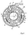
Fig. 2 , - Fig. 2
- eine Draufsicht, gesehen in Richtung des Pfeiles II der
Fig. 1 , - Fig. 3
- eine Seitenansicht des
Gehäuseteils 110 derFig. 4 , gesehen in Richtung des Pfeiles III derFig. 4 , - Fig. 4
- eine Draufsicht auf das
Gehäuseteil 110, gesehen in Richtung des Pfeiles IV derFig. 5 , - Fig. 5
- eine Seitenansicht des
Gehäuseteils 110, gesehen in Richtung des Pfeiles V derFig. 4 , - Fig. 6
- eine Seitenansicht des fertigen Lüfters, gesehen in Richtung des Pfeiles VI der
Fig. 7 - Fig. 7
- eine Draufsicht auf den fertigen Lüfter, gesehen in Richtung des Pfeiles VII der
Fig. 6 , - Fig. 8
- eine Seitenansicht des fertigen Lüfters, gesehen in Richtung des Pfeiles VIII der
Fig. 7 , - Fig. 9
- eine Seitenansicht des fertigen Lüfters, gesehen in Richtung des Pfeiles IX der
Fig. 7 , - Fig. 10
- ein Blockschaltbild einer bevorzugten Schaltung zur Fernsteuerung eines Lüfters nach der Erfindung über eine Steuerleitung (Bus),
- Fig. 11
- ein Schaltung analog
Fig. 10 mit weiteren Einzelheiten, - Fig. 12
- eine Draufsicht auf einen
Gerätelüfter 320 nach einem zweiten Ausführungsbeipiel der Erfindung, gesehen in Richtung eines Pfeiles XII derFig. 13 , - Fig. 13
- eine Seitenansicht, gesehen in Richtung des Pfeiles XIII der
Fig. 12 , - Fig. 14
- eine Draufsicht, gesehen in Richtung des Pfeiles XIV der
Fig. 13 , - Fig. 15
- eine teilweise im Schnitt dargestellte Seitenansicht, welche die Führung der elektrischen Anschlussleitungen darstellt, und
- Fig. 16
- zeigt ein bevorzugtes Ausführungsbeispiel der
Vorrichtung 150 ausFig. 11 .
- Fig. 1
- a section through a first embodiment of a fan according to the invention, as seen along the line I - I of
Fig. 2 . - Fig. 2
- a plan view, seen in the direction of arrow II of
Fig. 1 . - Fig. 3
- a side view of the
housing part 110 ofFig. 4 , seen in the direction of the arrow III of theFig. 4 . - Fig. 4
- a plan view of the
housing part 110, seen in the direction of arrow IV ofFig. 5 . - Fig. 5
- a side view of the
housing part 110, as seen in the direction of arrow V ofFig. 4 . - Fig. 6
- a side view of the finished fan, seen in the direction of arrow VI of
Fig. 7 - Fig. 7
- a plan view of the finished fan, seen in the direction of arrow VII of
Fig. 6 . - Fig. 8
- a side view of the finished fan, seen in the direction of arrow VIII of
Fig. 7 . - Fig. 9
- a side view of the finished fan, seen in the direction of arrow IX of
Fig. 7 . - Fig. 10
- a block diagram of a preferred circuit for the remote control of a fan according to the invention via a control line (bus),
- Fig. 11
- a circuit analog
Fig. 10 with more details, - Fig. 12
- a plan view of a
device fan 320 according to a second Ausführungsbeipiel the invention, as seen in the direction of an arrow XII ofFig. 13 . - Fig. 13
- a side view, seen in the direction of arrow XIII the
Fig. 12 . - Fig. 14
- a plan view, seen in the direction of the arrow XIV the
Fig. 13 . - Fig. 15
- a partially sectioned side view illustrating the leadership of the electrical leads, and
- Fig. 16
- shows a preferred embodiment of the
device 150 fromFig. 11 ,
Die Welle 32 hat am unteren Ende eine Ringnut 54, in welche ein Halteteil 56 federnd eingreift, das mittels einer Feder 58 im Lagertragrohr 24 fixiert ist.The
Auf der Außenseite des Lagertragrohres 24 ist ein Innenstator 60 befestigt. Dieser hat ein Blechpaket 62, in welchem mittels eines Spulenträgers 64, 66 eine Wicklung 68 befestigt ist. Ein Anschluss 70 der Wicklung 68 ist dargestellt. Er ist an einem im Spulenträger 66 befestigten Stift 72 angelötet.On the outside of the bearing
Die Nabe 22 ist einstückig mit Stegen 74 ausgebildet, welche die Nabe 22 mit einem im wesentlichen zylindrischen Mantelteil 76 verbinden, das die Lüfterflügel 46 radial mit Abstand umgibt, vgl.
Im Bereich der Nabe 22 sind drei Anschlussleitungen 86, 88 (+ und -) sowie 90 (Steuerleitung) angelötet und von dort über ein T-förmiges Klemmstück 92 auf der Außenseite des Mantelteils 76 und ein weiteres Klemmstück 94, ebenso auf der Außenseite des Mantelteiles 76, zu einem Anschlussstecker 96 geführt. Ferner befinden sich auf der Außenseite des Mantelteiles 76 vier radial abstehende Zapfen 98, welche als Rastzapfen dienen und welche hier in gleichen Abständen von 90° angeordnet sind.In the region of the
Die in
Die Darstellung gemäß
Die Darstellung gemäß
Zur Aufnahme der Leitungen 86, 88, 90, des T-Stückes 92 und des Klemmstückes 94 hat die zylindrische Ausnehmung 114 eine radiale Erweiterung 126, die sich über einen Winkel von etwa 20° erstreckt. Die Abdeckung dieser Erweiterung ist mit 130 bezeichnet und in
Das Gehäuse 110 hat an seinen Ecken Löcher 136 zur dauerhaften Befestigung dieses Teils an einem zu kühlenden Bauteil, z. B. einem Sendegerät, und es hat zwei vorstehende Zapfen 138 zur passgenauen Fixierung.The
Das Gehäuse 110 wird an dem zu kühlenden Teil dauerhaft montiert. Das Bauteil 100 (
Die
Die Entfernung des Bauteiles 100 aus dem Gehäuse 102 verläuft in umgekehrter Reihenfolge, d. h. das Bauteil 100 wird in Richtung des Pfeiles 82 um einige Grad im Gegenzeigersinn verdreht und dann axial aus dem Gehäuse 110 heraus gezogen.The removal of the
Wie in
Zum Verdrehen des Bauteiles 100 sind die Öffungen zwischen den radialen Stegen 74 und dem Ringsteg 80 so ausgebildet, dass man mit den Fingern in diese Öffnungen eingreifen und das Schutzgitter als Griffhilfe benutzen kann. Es ist darauf hinzuweisen, dass das in
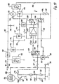
In
Zur Steuerung der Drehzahl des Motors 20 dient also ein Gleichspannungs-Steuersignal, oder aber ein PWM-Signal 164, das vom Steuergerät 156 über die Steuerleitung 90 zum Motor 20 geliefert, dort über ein Filter 158 in eine Gleichspannung an einer Leitung 159 umgesetzt und dem Drehzahlregler 152 als Sollwert nsoll zugeführt wird. Alternativ kann die Steuerung auch über eine Gleichspannung erfolgen, die dem Eingang 90 zugeführt wird und z.B. Werte zwischen 2 und 7 V haben kann. Die Gleichspannung nsoll an der Leitung 159 steigt mit zunehmendem Tastverhältnis pwm des PWM-Signals 164 an. Es gilt:
Wenn die Verbindung 90' vom Steuergerät 156 zur Steuerleitung 90 unterbrochen wird, würde der Drehzahlregler 152 ständig ein Signal erhalten, das einem PWM-Signal 164 mit dem Tastverhältnis 100 % entsprechen würde, und der Motor 20 würde mit maximaler Drehzahl laufen. Um dies zu verhindern, ist ein Schaltglied 160 vorgesehen, das in diesem Fall die Endstufe 154 sperrt, so dass der Motor 20 keinen Strom erhält und abgeschaltet wird. Dasselbe gilt für ein Tastverhältnis von > 95 %, das der Steuerleitung 90 zugeführt wird und das ebenfalls als Abschaltsignal interpretiert wird.If the connection 90 'from the
Wenn der Lüfter in einem Kraftfahrzeug verwendet wird, wird der Anschluss 86 an den Pluspol der (nicht dargestellten) Fahrzeugbatterie angeschlossen. Der Anschluss 86 ist mit einem Filter 166 zum EMI-Schutz verbunden, und zum Schutz gegen falschen Anschluss an die Batterie ist eine Diode 168 vorgesehen. Ferner ist ein Kondensator 170 vorgesehen, der den Motor 20 mit Blindleistung versorgt.When the fan is used in a motor vehicle, the terminal 86 is connected to the positive terminal of the vehicle battery (not shown). The terminal 86 is connected to a
Über eine interne Konstantspannungsquelle 172 wird an einer Leitung 174 eine stabilisierte Spannung von z.B. +7,7 V erzeugt, die über einen Kondensator 176 gefiltert wird. An die Leitung 174 ist der Hall-IC 50 angeschlossen, der vom permanentmagnetischen Rotor 42 (
In thermischer Verbindung mit dem Motor 20 und der Endstufe 154 (bzw. mit den beiden Transistoren 224, 226 in
In der Verbindung von der Endstufe 154 nach Masse 88 ist ein Messwiderstand 184 vorgesehen, an dem im Betrieb eine Spannung entsteht, die vom Strom i des Motors 20 abhängig ist und die einem Steuerglied 186 zugeführt wird.In the connection of the
Wird die Spannung am Widerstand 184 zu hoch, so erzeugt das Steuerglied 186 an einem Ausgang 188 ein Signal, das die Endstufe 154 sperrt, z.B. während 13 Sekunden, und es erzeugt an einem Ausgang 190 ein Signal, das einem npn-Transistor 192 zugeführt wird und diesen leitend macht.When the voltage across the
Der Emitter des Transistors 192 ist mit Masse 88 verbunden, sein Kollektor mit der Steuerleitung 90, d.h. wenn der Transistor 192 leitend ist, erhält die Steuerleitung 90 etwa das Potenzial von Masse 88.The emitter of
Im Steuergerät 156 ist die Leitung 90, 90' über einen Widerstand 194 mit dem Kollektor eines npn-Transistors 196 verbunden, dessen Emitter an Masse 88 liegt und dessen Basis im Betrieb das dargestellte PWM-Signal 164 zugeführt wird.In the
Wenn die Steuerleitung 90 durch den Transistor 192 mit Masse 88 verbunden ist, wirkt das, wie wenn das PWM-Signal 164 ein Tastverhältnis von 0 % hätte, und der Motor 20 wird abgeschaltet. Dasselbe gilt, wenn eine dem Eingang 90 zugeführte Gleichspannungs-Steuerspannung den Wert 0 annimmt.When the
Hierbei ist der Kollektor des Transistors 196 über einen Widerstand 198 mit einem Knotenpunkt 200 verbunden, und dieser ist über einen Widerstand 202 und einen dazu parallel geschalteten Kondensator 204 mit Masse 88 verbunden.Here, the collector of the transistor 196 is connected via a
Im normalen Betrieb lädt sich der Kondensator 204 durch die Impulse des PWM-Signals 164 auf, wozu auf
Über die Steuerleitung 90 gehen also die PWM-lmpulse 164 zum Drehzahlregler 152, und bei Störungen geht, weil der Transistor 192 leitend wird, ein Fehlersignal in umgekehrter Richtung vom Motor 20 zum Steuergerät 156.Thus, via the
Um zu verhindern, dass beim Start des Motors 20 ein zu hoher Strom i fließt, wird die Spannung am Widerstand 184 auch einem Steuerglied 208 zugeführt, das bei seinem Ansprechen den Strom i in der Endstufe 154 auf einen vorgegebenen Wert begrenzt. Während des Starts wird das Steuerglied 186 deaktiviert, d.h. dann ist nur die Anlaufstrombegrenzung 208 aktiv.In order to prevent an excessively high current i from flowing when starting the
Die Leitung 188 ist mit dem Ausgang des Reglers 152, dem Ausgang des Strombegrenzers 208 und einem Diodenglied 209 verbunden. Erzeugt der Regler 152, das Steuerglied 186, oder der Strombegrenzer 208 an seinem Ausgang ein niedriges Potenzial, so wird das Diodenglied 209 leitend, reduziert die Spannung an der Leitung 177, und sperrt dadurch die Endstufe 154 ganz oder Teilweise, so dass der Motor 20 entweder stromlos wird, oder - beim Anlauf - der Motorstrom i begrenzt wird.The
Die Solldrehzahl des Motors 20 wird über eine Gleichspannung (hier: 2...7 V) am Eingang 90 oder durch das Tastverhältnis pwm des PWM-Signals 164 vorgegeben. Solange dieses kleiner als 10 % ist, steht der Motor 20. Im Bereich von 30 bis 85 % nimmt die Drehzahl zu. Bei einem Tastverhältnis über 95 % wird der Motor über das Schaltglied 160 abgeschaltet, wie bereits beschrieben.The setpoint speed of the
Beim Start wird der Motorstrom i durch das Steuerglied 208 auf einen vorgegebenen Höchstwert begrenzt, indem über das Diodenglied 209 das Steuersignal für die Endstufe 154 entsprechend reduziert wird, wenn der Anlaufstrom i zu hoch wird.At startup, the motor current i is limited by the
Wird der Motor 20 blockiert, so steigt der Strom i stark an, und dieser Überstrom bewirkt, dass das Steuerglied 186 über das Diodenglied 209 und die Endstufe 154 den Motor 20 ausschaltet, z.B. 13 Sekunden lang, und dann den Motor 20 z.B. während zwei Sekunden einschaltet, um einen neuen Start des Motors zu versuchen. Durch dieses periodische Ein- und Ausschalten wird verhindert, dass der Motor 20 und seine Endstufe 154 zu heiß werden, wenn der Motor 20 an einer Drehung gehindert ist.When the
Das vom Steuerglied 186 hierbei erzeugte periodische Signal wird über die Leitung 190 auch dem npn-Transistor 192 zugeführt und bewirkt, dass dieser periodisch ein- und ausgeschaltet wird. Dadurch wird auch das Potenzial am Punkt 90 periodisch verändert und über die Steuerleitung 90' zum Steuergerät 156 übertragen, wo es das schon beschriebene Fehlersignal FAULT erzeugt.The periodic signal generated thereby by the
Wird einer der Transistoren 234, 236 leitend gesteuert, so wird eine Verbindung von der Basis der Transistoren 224, 226 nach Masse hergestellt, so dass diese Transistoren gesperrt werden und der Motor 20 keinen Strom mehr erhält. Wird einer der Transistoren 234, 236 nur teilweise leitend, so reduziert er den Basisstrom der Transistoren 224, 226, so dass der Motorstrom i entsprechend abnimmt. Dies geschieht bei der Strombegrenzung, vor allem beim Start des Motors 20.If one of the
Die Emitter der Transistoren 224, 226 sind über einen Knotenpunkt 240 und den Messwiderstand 184 mit Masse 88 verbunden. Das Potenzial am Knotenpunkt 240 wird über einen Widerstand 242 der Basis des Transistors 236 zugeführt, so dass dieser als Strombegrenzer wirkt, d.h. mit zunehmender Spannung am Widerstand 184 wird der Transistor 236 immer mehr leitend und begrenzt dadurch den Motorstrom i, z.B. auf einen Höchstwert von etwa 0,5 A beim Start.The emitters of the
Das Potenzial am Knotenpunkt 240 wird auch dem Pluseingang eines OP-Verstärkers 244 zugeführt, dessen Minuseingang an einem Knotenpunkt 246 liegt, der über einen Widerstand 248 mit Masse 88 und über den PTC-Widerstand 180 und einen Widerstand 250 mit der Leitung 174 verbunden ist.The potential at
Der Ausgang 252 des OP-Verstärkers 244 ist über einen Kondensator 254 (z.B. 2,2 µF) mit dem Pluseingang, über einen Widerstand 256 (z.B. 100 kOhm) mit dem Knotenpunkt 246, über einen Widerstand 258 mit der Basis des Transistors 234, über einen Kondensator 260 (z.B. 1 nF) mit Masse 88 und über einen Widerstand 262 mit der Basis des Transistors 192 verbunden. Die Basis des Transistors 234 ist auch über einen Widerstand 264 mit Masse 88 verbunden.The
Wenn der Motorstrom i durch ein mechanisches Blockieren des Motors 20 dauerhaft zu hoch wird, schaltet der OP-Verstärker 244 seinen Ausgang 252 auf High, wodurch der Transistor 234 leitend wird und, wie beschrieben, den Motor 20 stromlos macht. Gleichzeitig wird über den Widerstand 262 auch der Transistor 192 eingeschaltet und erzeugt ein niedriges Potenzial auf der Steuerleitung 90.When the motor current i becomes permanently too high due to mechanical blocking of the
Wenn der OP-Verstärker 244 umgeschaltet hat, bleibt er durch die Wirkung des Kondensators 254 etwa 13 Sekunden lang in diesem Zustand und schaltet dann wieder in den Zustand zurück, in dem sein Ausgang niedrig ist, wodurch die Transistoren 192 und 234 wieder gesperrt werden und der Motor 20 wieder Strom erhält. Ist er weiterhin blockiert, so wird er ca. 2 Sekunden lang eingeschaltet, und wenn er nicht startet, erneut 13 Sekunden lang stromlos gemacht.When the
Sollte der Motor 20 durch Überlastung und/oder erhöhte Umgebungstemperaturen (Sommer) zu heiß werden, wird der PTC-Widerstand 180 hochohmig, wodurch das Potenzial am Knotenpunkt 246 sinkt und dadurch ebenfalls die Transistoren 192 und 234 eingeschaltet werden und der Motor 20 stromlos gemacht wird, bis die Temperatur am PTC-Widerstand 180 wieder genügend weit gesunken ist.Should the
Der Drehzahlregler 152 arbeitet mit einem Vergleich der Signale nist und nsoll. Hierzu hat er einen OP-Verstärker 152K, dem diese Signale zugeführt werden. Ist die Drehzahl des Motors 20 zu hoch,so wird der Ausgang 270 des OP-Verstärkers 152K hoch, und dieses Signal wird über einen Widerstand 272 zur Basis des Transistors 236 übertragen, macht diesen leitend, und beeinflusst dadurch die Transistoren 224, 226, so dass der Motorstrom i und damit die Drehzahl des Motors 20 abnimmt.The
Die Steuerleitung 90 ist über einen Widerstand 276 mit der Leitung 174 und über einen Widerstand 278 mit einem Knotenpunkt 280 verbunden, der über einen Kondensator 282 mit Masse 88 und über einen Widerstand 284 mit dem Minuseingang des OP-Verstärkers 152K verbunden ist. Dieser Minuseingang ist auch über einen Widerstand 286 mit Masse verbunden.The
Die Steuerleitung 90 ist über einen Widerstand 290 mit der Basis eines pnp-Transistors 292 verbunden, dessen Emitter, ebenso wie der Emitter eines pnp-Transistors 294, an der Leitung 174 liegt.The
Der Kollektor des Transistors 292 ist über einen Widerstand 296 mit Masse 88 und über einen Kondensator 298 mit dessen Basis verbunden. Diese Basis ist auch über einen Widerstand 300 mit dem Kollektor des Transistors 294 verbunden, der über einen Widerstand 302 mit der Basis des Transistors 236 verbunden ist.The collector of
Wenn der Transistor 294 leitend ist, führt er dem Transistor 236 einen Basisstrom zu und sperrt dadurch die Transistoren 224, 226, so dass der Motor 20 stromlos wird.When
Solange das Tastverhältnis des PWM-Signals (vgl. 164 in
Überschreitet das Tastverhältnis des PWM-Signals an der Steuerleitung 90 den Wert 95 %, oder die Steuerleitung 90' (
Eine Unterbrechung der Steuerleitung 90' (
Auf diese Weise können über die Steuerleitung 90 in beiden Richtungen Signale übertragen werden, also in der Richtung zum Motor 20 Signale (PWM-Signale 164 oder eine Steuer-Gleichspannung), welche die Motordrehzahl steuern, und in umgekehrter Richtung ein Fehlersignal, wenn der Motor 20 zu langsam läuft oder an einer Drehung gehindert ist.In this way signals can be transmitted via the
Die
Genau wie bei dem Lüfter nach den
Der Lüfter 330 hat eine Nabe 332, die über drei Stege 334 mit einem rohrförmigen Außenteil 336 verbunden ist, dessen Außenseite 338 mit Gleitsitz in die Ausnehmung 328 passt.The
Auf der Außenseite 328 sind mit 180° Abstand zwei radial vorstehende Zapfen 340 vorgesehen, von denen nur einer (in
Der Lüfter 330 hat fünf Lüfterflügel 348, die auf einem Außenrotor 360 befestigt sind. Zum elektrischen Anschluss des Innenstators 362 sind drei Leitungen 364, 366, 368 vorgesehen, die hier zu einer (nicht dargestellten) Elektronik außerhalb des Lüfterteils 330 führen, da bei einem derart kleinen Gerätelüfter die Elektronik im Lüfter 330 selbst nicht genügend Platz haben würde. Wie
Zur Aufnahme der Leitungen 364, 366, 368 und der Halteteile 370, 372 ist das Außengehäuse 322 auch hier mit einer radialen Erweiterung 380 versehen, deren Abdeckung mit 382 bezeichnet ist. Ihre radiale Erstreckung ermöglicht es, das Lüfterteil 330 im Außengehäuse 322 so weit zu verdrehen, wie das zum Verriegeln und Entriegeln notwendig ist.To accommodate the
Zur Vermeidung von Längen wird zur Erläuterung der Wirkungsweise des zweiten Ausführungsbeispiels (
Naturgemäß sind im Rahmen der vorliegenden Erfindung vielfache Abwandlungen und Modifikationen möglich. Z.B. könnten die Rastvorsprünge 94 auf der Innenseite der Ausnehmung 114 vorgesehen werden, und das Mantelteil 76 könnte entsprechende Rastausnehmungen haben. Bei
Die Schaltung 150 weist ein Verstärkungsglied in Form eines pnp-Transistors 400 (bevorzugt BC856B) auf, dessen Basis über einen Widerstand 402 (bevorzugt 1 kΩ) mit der Plusleitung 86 verbunden ist, eine Auskopplungsvorrichtung 404, 406 in Form von zwei Dioden 404, 406 (bevorzugt BAV70), deren Anoden jeweils mit der von der mit der Plusleitung 86 verbundenen Seite abgewandten Seite der Statorwicklungsphasen 220, 222 verbunden sind, und deren Kathoden mit einem Punkt 408 verbunden sind, einen Widerstand 410 (bevorzugt 39 kΩ), welcher zwischen dem Punkt 408 und dem Emitter des Transistors 400 angeordnet ist, und eine Glättungsvorrichtung in Form eines Kondensators 414 (bevorzugt 100 nF), welcher Kondensator 414 zwischen der Basis und dem Kollektor des Transistors 400 angeordnet ist. Der Kollektor des Transistors 400 ist über einen Widerstand 418 (bevorzugt 36 kΩ) mit der Masseleitung 88 verbunden, wobei an einem Punkt 412 zwischen dem Kollektor des Transistors 400 und dem Widerstand 418 eine drehzahlabhängige und der Drehzahl proportionale Spannung abgegriffen werden kann.The
Die Basis des Transistors 400 liegt über den Widerstand 402 an der Plusleitung 86. Sobald einer der Transistoren 224, 226, beispielsweise der Transistor 224, im Betrieb öffnet, arbeitet die Phase 220 im generatorischen Betrieb, und das Potenzial am Punkt 408 wird durch die in die Statorwicklungsphase 220 induzierte, der Drehzahl nist proportionale Spannung, welche zu dem Potenzial der Plusleitung 86 addiert wird, größer als das Potenzial an der Plusleitung 86.The base of
Dadurch wird der als Verstärkungsglied arbeitende Transistor 400 leitend, und ein Strom fließt über den Widerstand 410, den Transistor 400 und den Widerstand 418 zur Masseleitung 88.As a result, the
Dieser Strom ist entsprechend der in die Statorwicklungsphase 220 induzierten Spannung wellig. Diese Welligkeit wird durch eine Wechselstromgegenkopplung mittels des Kondensators 414 beseitigt, so dass ein der Rotordrehzahl proportionaler Gleichstrom über den Widerstand 418 zur Masseleitung 88 fließt. Dadurch erhält man am Punkt 412 ein der Rotordrehzahl proportionales Potenzial.This current is wavy according to the voltage induced in the
Dem Potenzial am Punkt 412 wird über die Diode 420 und den Widerstand 422 die Diodenspannung der Diode 420 aufaddiert, und das Ergebnis wird über den Ausgang nist dem Operationsverstärker 152 zugeführt, vgl.
Vorteilhaft an dieser Schaltung 150 ist, dass sie unabhängig von der Höhe der verwendeten Betriebsspannung 86 funktioniert und ein Signal nist liefert, das der augenblicklichen Drehzahl des Motors 20 proportional ist.An advantage of this
Claims (31)
- Equipment fan with a drive motor (20), which equipment fan, in addition to its supply lines (86, 88) for the power supply to the drive motor (20), has a control line (90), via which a signal (164) from outside is supplied to this drive motor (20), wherein the signal (164) is a PWM signal and assigned to the drive motor (20) is a device (152; 186), which is formed to influence the speed of the drive motor (20) depending on this signal (164),
and with a device (152; 186) assigned to the drive motor (20) for producing a fault signal, which device is activated if a preset fault condition exists,
wherein the control line (90), via which a signal (164) from outside (156) is supplied to the drive motor (20), is formed to transmit signals in both directions and also serves to transmit the fault signal from the device (152; 186) assigned to the drive motor (20) outwards,
wherein the drive motor (20) is a brushless motor, wherein the device (152; 186) for influencing the speed of the drive motor (20) has a speed governor (152), the target speed (n target) of which is predetermined via the signal (164) supplied from outside,
wherein the equipment fan is formed to facilitate a switch-off of the drive motor (20) depending on the signal (164) supplied from outside,
and wherein assigned to the drive motor (20) is a switching element (192), which can be activated by the device (152; 186) for producing a fault signal, in order to change the potential at the control line (90) during this activation of the switching element (192). - Equipment fan with a drive motor (20), which equipment fan, in addition to its supply lines (86, 88) for the power supply to the drive motor (20), has a control line (90), via which a signal (164) from outside is supplied to this drive motor (20), wherein the signal (164) is a direct voltage signal and assigned to the drive motor (20) is a device (152; 186), which is formed to influence the speed of the drive motor (20) depending on this signal (164),
and with a device (152; 186) assigned to the drive motor (20) for producing a fault signal, which device is activated if a preset fault condition exists,
wherein the control line (90), via which a signal (164) from outside (156) is supplied to the drive motor (20), is formed to transmit signals in both directions and also serves to transmit the fault signal from the device (152; 186) assigned to the drive motor (20) outwards,
wherein the drive motor (20) is a brushless motor, wherein the device (152; 186) for influencing the speed of the drive motor (20) has a speed governor (152), the target speed (n target) of which is predetermined via the signal (164) supplied from outside,
wherein the equipment fan is formed to facilitate a switch-off of the drive motor (20) depending on the signal (164) supplied from outside,
and wherein assigned to the drive motor (20) is a switching element (192), which can be activated by the device (152; 186) for producing a fault signal, in order to change the potential at the control line (90) during this activation of the switching element (192). - Equipment fan according to one of the preceding claims, in which a switch-off device (160, 276, 282) is provided, which can be activated by the occurrence of an extreme value at the control line (90) to switch the drive motor (20) off.
- Equipment fan according to claim 1, in which the PWM signal (184) supplied via the control line (90) can be supplied to a voltage divider (276, 278, 284, 286), in which connected in parallel to a partial resistor (286) is a capacitor (282), the charge state of which is a function of the duty cycle of the PWM signal (164),
and the switch-off device (160) can be activated by a partial voltage occurring at this voltage divider (276, 278, 284, 286) if the latter assumes a predetermined value in the case of an extreme value of the duty cycle of the PWM signal (164). - Equipment fan according to claim 4, in which the switch-off device (160) can be activated by a value of the partial voltage that occurs if the control line (90) to the equipment fan is interrupted.
- Equipment fan according to one of the preceding claims, in which the switching element (192) can be activated if the motor (20) is switched off by the occurrence of an excess temperature.
- Equipment fan according to one of the preceding claims, in which the switching element (192) can be activated if the motor (20) is switched off as a result of too low a speed.
- Equipment fan according to one of the preceding claims, which is formed so that the motor (20) is switched off and on periodically when an overcurrent occurs.
- Equipment fan according to one of the preceding claims,
with a fan wheel (46; 348), which can be driven by an external rotor motor serving as a drive motor (20), the inner stator (60; 362) of which is attached to a hub (22; 332), which for its part is connected via at least one web (74; 334) to a roughly cylindrical sleeve part (76; 336) surrounding the outside of the fan wheel (46; 348) at a distance,
and with a housing (110; 322) formed for the detachable take-up of this sleeve part (76; 336), which housing is formed for its part for attachment to an object (136, 138). - Equipment fan according to claim 9, in which provided on the hub (22; 332) is an electrical connection line (86,88,90; 364,366,368), for the fixing of which on the outside (338) of the sleeve part (76; 336) at least one holding element (92,94; 370,372) is provided, wherein the connection line (86,88,90; 364,366,368) extends from the hub (22; 332) to the outside of the sleeve part (76; 336) and to the at least one holding element (92,94; 370,372) provided there.
- Equipment fan according to claim 10, in which provided on the inside of the housing (110; 322) is a recess (126; 380) to receive the at least one holding element (92,94; 370,372) and the connection line (86,88,90; 364,366,368) held on it.
- Equipment fan according to one of claims 9 to 11, in which provided on the outside of the sleeve part (76; 336) is a lug (98; 340), and in which provided in the housing (110; 322) is a member (120,122,124; 342,344) for locking this lug (98; 340), in which this lug (98; 340) latches when the sleeve part (76; 336) is in a preset position relative to the housing (110; 322) or vice-versa.
- Equipment fan according to claim 12, in which the member used for locking is formed as an elastic latching member (120,122,124; 348), in which the lug (98; 340) is insertable and lockable by a combination of axial movement and rotary movement of the sleeve part (76; 336) relative to the housing (110; 322).
- Equipment fan according to one of claims 9 to 13, in which the housing (110; 322) is provided on one side with a housing protective grid (112; 326) for the passage of air.
- Equipment fan according to claim 14, in which hub (22; 332) and sleeve part (76; 336) are provided on a side facing away from the housing protective grid (112; 326) with a protective grid (74,80; 334), so that the equipment fan has a protective grid on both sides following the connection of sleeve part (76; 336) and housing (110; 322).
- Equipment fan according to claim 15, in which the protective grid (74, 80) provided on hub (22) and sleeve part (76) has openings, which permit a fingertip to be inserted through, in order to facilitate a movement of the sleeve part (76) relative to the housing (110) by grasping this protective grid (74, 80) manually.
- Equipment fan according to claim 15 or 16, in which the protective grid (74, 80) provided on hub (22) and sleeve part (76) is provided with at least one marking (82,84,122), which indicates the opening and/or closing direction in which the sleeve part (76) must be twisted relative to the housing (110) to initiate the relevant process.
- Equipment fan according to one of claims 9 to 17, in which the housing (110; 322) for receiving the sleeve part (76; 336) detachably has a substantially cylindrical recess (114; 328) at least in areas.
- Equipment fan according to claim 18, in which the roughly cylindrical recess (114; 328) has a discontinuity (118; 342) at least in areas in order to facilitate there the introduction of a lug (98; 340) provided on the outside of the sleeve part (76; 336).
- Equipment fan according to claim 19, in which the discontinuity (118; 342) in the roughly cylindrical recess (114; 328) has an elastic latching member (122,124; 346), which facilitates latching of the lug (98; 340) provided on the sleeve part (76; 336) by a relative rotation between housing (110; 322) and sleeve part (76; 336).
- Equipment fan according to one of claims 9 to 20, in which the housing (110), seen in an axial direction of the fan, has a roughly rectangular and in particular a square outer circumference.
- Equipment fan according to one of claims 18 to 20, and according to claim 24, in which a section (116) of the housing (110) forming the roughly cylindrical recess (114) protrudes over the rectangular outer circumference at least in areas.
- Equipment fan according to one of claims 9 to 22, in which provided on the housing (110) is a holding device (132) for a plug (96), which is provided on an electrical connection line (86,88,90) of the external rotor motor (20).
- Equipment fan according to one of the preceding claims, which has an arrangement for producing a speed-dependent signal,
with at least one winding (220, 222), in which a speed-dependent voltage is induced in operation by a rotating permanent magnet rotor,
with a diode (404, 406) for decoupling a decoupling signal (408) influenced by the induced voltage from the winding (220,222) when no drive current is flowing in this,
and with an amplifying device (400,402,410) to amplify the decoupling signal (408) to produce the speed-dependent signal (412). - Equipment fan according to claim 24, in which the amplifying device has a transistor (400) for amplifying the decoupling signal.
- Equipment fan according to claim 24 or 25, in which a smoothing device (414) is provided for smoothing the speed-dependent signal (412).
- Equipment fan according to claim 26, in which the smoothing device (414) has an alternating current negative feedback for smoothing the speed-dependent signal (412).
- Equipment fan according to claim 27, in which the amplifying device has an amplifying element (400), and in which the alternating current negative feedback (414) is effected by a capacitor (414), which is provided between an output and an input of the amplifying element.
- Equipment fan according to one of claims 24 to 28, with a resistor (418), one end of which is connected to ground and the other end of which is connected to the decoupling signal amplified by the amplifying device (400,402,410), in order to produce the speed-dependent signal via the voltage falling at the resistor (418).
- Equipment fan according to one of claims 24 to 29, with at least two windings (220,222), assigned to each of which is a diode (404,406) for decoupling a decoupling signal, wherein the decoupling signals are brought together and amplified by a common amplifying device.
- Equipment fan according to one of claims 24 to 30, with a diode (420), which increases the speed-dependent signal by the diode voltage.
Applications Claiming Priority (4)
| Application Number | Priority Date | Filing Date | Title |
|---|---|---|---|
| DE20119155U | 2001-11-26 | ||
| DE20119155 | 2001-11-26 | ||
| DE20210846 | 2002-07-18 | ||
| DE20210846U | 2002-07-18 |
Publications (4)
| Publication Number | Publication Date |
|---|---|
| EP1314894A2 EP1314894A2 (en) | 2003-05-28 |
| EP1314894A3 EP1314894A3 (en) | 2003-11-05 |
| EP1314894B1 EP1314894B1 (en) | 2006-05-17 |
| EP1314894B2 true EP1314894B2 (en) | 2012-05-09 |
Family
ID=26057292
Family Applications (1)
| Application Number | Title | Priority Date | Filing Date |
|---|---|---|---|
| EP02023117A Expired - Lifetime EP1314894B2 (en) | 2001-11-26 | 2002-10-15 | Fan |
Country Status (4)
| Country | Link |
|---|---|
| US (2) | US6864653B2 (en) |
| EP (1) | EP1314894B2 (en) |
| AT (1) | ATE326635T1 (en) |
| DE (2) | DE20215697U1 (en) |
Cited By (2)
| Publication number | Priority date | Publication date | Assignee | Title |
|---|---|---|---|---|
| DE102014206277A1 (en) | 2014-04-02 | 2015-10-08 | BSH Hausgeräte GmbH | Home appliance device |
| DE202015106847U1 (en) | 2015-12-16 | 2017-03-17 | Elektrosil Systeme Der Elektronik Gmbh | Fan with status signal generation and transmission of the status signal via a supply line |
Families Citing this family (31)
| Publication number | Priority date | Publication date | Assignee | Title |
|---|---|---|---|---|
| DE50111285D1 (en) * | 2000-08-30 | 2006-11-30 | Ebm Papst St Georgen Gmbh & Co | METHOD FOR REGULATING THE ELECTRICITY IN A DC MACHINE FOR A FAN |
| US6924979B2 (en) * | 2001-07-30 | 2005-08-02 | Hewlett-Packard Development Company, L.P. | Mounting apparatus for coupling control circuitry to an air moving device |
| DE10310830A1 (en) | 2003-03-13 | 2004-09-23 | Robert Bosch Gmbh | Control of a ventilation system with two or more fans, whereby pulse width modulated signals with different time periods are used to control the fans in conjunction with each other to generate a desired ventilation output |
| EP1725775B1 (en) * | 2004-03-16 | 2008-10-15 | ebm-papst St. Georgen GmbH & Co. KG | Arrangement with an electronically commutated external rotor motor |
| JP2005303015A (en) * | 2004-04-12 | 2005-10-27 | Nippon Densan Corp | Heatsink fan |
| ATE371984T1 (en) * | 2004-05-12 | 2007-09-15 | Ebm Papst St Georgen Gmbh & Co | ELECTRONICALLY COMMUTATED TWO-PULSE MOTOR AND METHOD FOR STARTING SUCH A MOTOR |
| JP4702017B2 (en) * | 2005-12-02 | 2011-06-15 | 株式会社デンソー | Motor drive device for blower of in-vehicle air conditioner |
| US7602157B2 (en) | 2005-12-28 | 2009-10-13 | Flyback Energy, Inc. | Supply architecture for inductive loads |
| TWI340534B (en) * | 2006-10-25 | 2011-04-11 | Sunonwealth Electr Mach Ind Co | Pwm motor drive circuit |
| US20080247689A1 (en) * | 2007-04-06 | 2008-10-09 | Nidec Corporation | Motor |
| US20080286093A1 (en) * | 2007-05-16 | 2008-11-20 | Bauer Jr Thomas | Cooler Fan Hub |
| JP4946625B2 (en) * | 2007-05-21 | 2012-06-06 | 日本電産株式会社 | motor |
| US8398378B2 (en) * | 2007-07-24 | 2013-03-19 | Brose Fahrzeugteile GmbH & Co. Kommanditgesellschaft, Würzburg | Tangential drive module assembly and method of assembly for airflow induction |
| WO2009039305A2 (en) * | 2007-09-18 | 2009-03-26 | Flyback Energy, Inc. | Current waveform construction to generate ac power with low harmonic distortion from localized energy sources |
| US8672649B2 (en) | 2007-10-10 | 2014-03-18 | Delta T Corporation | Ceiling fan system with brushless motor |
| US20090110573A1 (en) * | 2007-10-26 | 2009-04-30 | Hoyt Robert A | Apparatus and Method for Retaining and Isolating Modular Fan and Motor Sub-Assemblies in Air Moving Systems |
| ITBO20070776A1 (en) | 2007-11-23 | 2009-05-24 | Spal Automotive Srl | VENTILATION UNIT IN PARTICULAR FOR MOTOR VEHICLES. |
| CN101714812A (en) * | 2008-10-08 | 2010-05-26 | 鸿富锦精密工业(深圳)有限公司 | Fan control circuit |
| TWI467914B (en) * | 2008-10-17 | 2015-01-01 | Hon Hai Prec Ind Co Ltd | Fan control circuit |
| TW201020400A (en) * | 2008-11-27 | 2010-06-01 | Compal Electronics Inc | Fan module for electronic device |
| DE102009053620A1 (en) | 2009-11-17 | 2011-05-19 | Ziehl-Abegg Ag | Control electronics-integrated external rotor motor for connection with e.g. mini terminal to drive ventilators, has control electronics controlling motor, during detected interruption, and allowing user configuration of program |
| WO2011082188A1 (en) * | 2009-12-28 | 2011-07-07 | Flyback Energy Inc. | External field interaction motor |
| CA2785715A1 (en) * | 2009-12-28 | 2011-07-28 | Paul M. Babcock | Controllable universal supply with reactive power management |
| US8610387B2 (en) * | 2010-04-30 | 2013-12-17 | Sunonwealth Electric Machine Industry Co., Ltd. | Motor system |
| JP6281250B2 (en) * | 2013-11-11 | 2018-02-21 | 日本電産株式会社 | motor |
| DE102013017975A1 (en) * | 2013-11-29 | 2015-06-03 | Fte Automotive Gmbh | Electric motor driven liquid pump, in particular for forced lubrication of a manual transmission for motor vehicles |
| JP6330219B2 (en) * | 2014-03-17 | 2018-05-30 | 株式会社デンソー | Motor control device |
| US10184475B2 (en) | 2015-07-20 | 2019-01-22 | Delphi Technologies Ip Limited | Fluid pump with flow impedance member |
| JP2018178802A (en) * | 2017-04-07 | 2018-11-15 | 日本電産株式会社 | Fan motor |
| DE102017111826A1 (en) * | 2017-05-30 | 2018-12-06 | Ebm-Papst Mulfingen Gmbh & Co. Kg | Device for reducing harmful bearing stresses |
| TWM550341U (en) * | 2017-07-24 | 2017-10-11 | Dongguan City Hanshuo Plastic Co Ltd | Structure of quick release type wire-free cooling fan |
Citations (6)
| Publication number | Priority date | Publication date | Assignee | Title |
|---|---|---|---|---|
| DE4033092A1 (en) † | 1990-10-18 | 1992-04-23 | Telefunken Electronic Gmbh | Tandem cooler with single controller for motor vehicle - supplies air for engine cooling and passenger compartment ventilation purposes from two power transistor-driven fans |
| DE4225534A1 (en) † | 1992-08-01 | 1994-02-03 | Rolf Gnauert | Electric motor operating and monitoring circuit for underground mining equipment - uses amplitude shifting keying data to modulate energy supply line with motor control data |
| DE19736300A1 (en) † | 1996-09-26 | 1998-04-02 | Valeo Electronique | Electronically controlled electric motor esp. for vehicle ventilator |
| DE19703516C1 (en) † | 1997-01-31 | 1998-05-07 | Daimler Benz Ag | Vehicle seat with upholstery heating and cooling |
| DE19826458A1 (en) † | 1998-06-13 | 1999-12-16 | Papst Motoren Gmbh & Co Kg | Arrangement with an electric motor |
| DE10009128C1 (en) † | 2000-02-26 | 2001-08-16 | Wet Automotive Systems Ag | Device for aerating a vehicle seat has one or more fans fitted in a vehicle seat to be controlled by a central seat control transmitting control signals through a data line to control electronics in a fan casing |
Family Cites Families (30)
| Publication number | Priority date | Publication date | Assignee | Title |
|---|---|---|---|---|
| CH654455A5 (en) * | 1980-05-10 | 1986-02-14 | Papst Motoren Gmbh & Co Kg | BRUSHLESS DC MOTOR ARRANGEMENT, ESPECIALLY FOR MAGNETIC DISC DRIVES. |
| DE3404466A1 (en) | 1984-02-08 | 1985-08-08 | Ebm Elektrobau Mulfingen Gmbh & Co, 7119 Mulfingen | EXTERNAL ROTOR MOTOR |
| US4554491A (en) * | 1984-08-10 | 1985-11-19 | Msl Industries, Inc. | Brushless DC motor having a laminated stator with a single stator winding |
| DE3542214A1 (en) | 1984-12-03 | 1986-06-05 | Papst-Motoren GmbH & Co KG, 7742 St Georgen | Fan |
| DE3546683C3 (en) | 1985-02-22 | 2003-10-09 | Bosch Gmbh Robert | Method for operating a data processing system |
| DE3820857C2 (en) | 1988-06-04 | 1993-12-02 | Licentia Gmbh | Electric motor with an external rotor and a fan wheel connected to it |
| US4949022A (en) * | 1989-01-27 | 1990-08-14 | Lipman Leonard H | Solid state DC fan motor |
| US5099181A (en) * | 1991-05-03 | 1992-03-24 | Canon K N Hsu | Pulse-width modulation speed controllable DC brushless cooling fan |
| US5208730A (en) * | 1991-06-27 | 1993-05-04 | Compaq Computer Corporation | Computer cooling fan vibration isolation apparatus |
| DE4127134B4 (en) | 1991-08-15 | 2004-07-08 | Papst Licensing Gmbh & Co. Kg | diagonal fan |
| DE4143663B4 (en) | 1991-12-13 | 2007-03-29 | Papst Licensing Gmbh & Co. Kg | centrifugal blower |
| US5845045A (en) | 1993-11-28 | 1998-12-01 | Papst-Motoren Gmbh & Co. Kg | Method and apparatus for DC motor speed control |
| KR0135898B1 (en) * | 1995-02-24 | 1998-06-15 | 김광호 | Fan controlling device |
| US5638895A (en) * | 1996-03-25 | 1997-06-17 | Dodson; Douglas A. | Twin fan cooling device |
| DE19628698C1 (en) | 1996-07-17 | 1997-10-09 | Daimler Benz Ag | Ventilated seat for use in vehicle |
| US6695046B1 (en) * | 1997-02-18 | 2004-02-24 | Hoffman Controls Corp. | Variable speed fan motor control for forced air heating/cooling system |
| TW338585U (en) | 1997-07-15 | 1998-08-11 | Asia Vital Components Co Ltd | Improvement on a non-carbon brush DC fan |
| GB9717242D0 (en) | 1997-08-15 | 1997-10-22 | Minebea Electronics Uk Ltd | Circuit |
| US5947691A (en) * | 1997-10-29 | 1999-09-07 | Comair Rotron, Inc. | Winding supply circuit with current and thermal protective elements |
| US6075698A (en) * | 1998-10-27 | 2000-06-13 | Ads, The Power Resource, Inc. | Removable fan for rack mounted rectifiers |
| DE29819962U1 (en) | 1998-11-09 | 2000-03-23 | Mulfingen Elektrobau Ebm | Radial blower with connector |
| US5977733A (en) | 1998-12-08 | 1999-11-02 | Shin Jiuh Corporation | Fan control device with breakdown warning capability |
| US6147465A (en) * | 1999-03-25 | 2000-11-14 | General Electric Company | Microprocessor controlled single phase motor with external rotor having integral fan |
| US6183221B1 (en) | 1999-10-29 | 2001-02-06 | Hsieh Hsin-Mao | Heat dissipation fan with a shaft positioned to prevent chafing between the fan blades and the bearing |
| US6528987B1 (en) * | 2000-06-19 | 2003-03-04 | Analog Devices, Inc. | Method and apparatus for determining fan speed |
| US6262549B1 (en) | 2000-06-29 | 2001-07-17 | System General Corp. | Fan speed pulse filter for a PWM fan |
| US6747424B1 (en) * | 2000-10-02 | 2004-06-08 | International Business Machines Corporation | Integrated fan speed control and fault detection circuitry |
| US6517318B2 (en) | 2000-12-11 | 2003-02-11 | Hsieh Hsin-Mao | Buffer pad for use in an electric fan |
| US6690576B2 (en) * | 2001-07-31 | 2004-02-10 | Hewlett Packard Development Company, L.P. | Externally mounted on-line replaceable fan module |
| US6376946B1 (en) * | 2001-08-23 | 2002-04-23 | Bill Lee | D.C. brushless air fan with an annular oil trough |
-
2002
- 2002-09-30 US US10/262,400 patent/US6864653B2/en not_active Expired - Fee Related
- 2002-10-12 DE DE20215697U patent/DE20215697U1/en not_active Expired - Lifetime
- 2002-10-15 DE DE50206794T patent/DE50206794D1/en not_active Expired - Lifetime
- 2002-10-15 EP EP02023117A patent/EP1314894B2/en not_active Expired - Lifetime
- 2002-10-15 AT AT02023117T patent/ATE326635T1/en not_active IP Right Cessation
-
2004
- 2004-11-05 US US10/982,307 patent/US7352094B2/en not_active Expired - Fee Related
Patent Citations (6)
| Publication number | Priority date | Publication date | Assignee | Title |
|---|---|---|---|---|
| DE4033092A1 (en) † | 1990-10-18 | 1992-04-23 | Telefunken Electronic Gmbh | Tandem cooler with single controller for motor vehicle - supplies air for engine cooling and passenger compartment ventilation purposes from two power transistor-driven fans |
| DE4225534A1 (en) † | 1992-08-01 | 1994-02-03 | Rolf Gnauert | Electric motor operating and monitoring circuit for underground mining equipment - uses amplitude shifting keying data to modulate energy supply line with motor control data |
| DE19736300A1 (en) † | 1996-09-26 | 1998-04-02 | Valeo Electronique | Electronically controlled electric motor esp. for vehicle ventilator |
| DE19703516C1 (en) † | 1997-01-31 | 1998-05-07 | Daimler Benz Ag | Vehicle seat with upholstery heating and cooling |
| DE19826458A1 (en) † | 1998-06-13 | 1999-12-16 | Papst Motoren Gmbh & Co Kg | Arrangement with an electric motor |
| DE10009128C1 (en) † | 2000-02-26 | 2001-08-16 | Wet Automotive Systems Ag | Device for aerating a vehicle seat has one or more fans fitted in a vehicle seat to be controlled by a central seat control transmitting control signals through a data line to control electronics in a fan casing |
Cited By (3)
| Publication number | Priority date | Publication date | Assignee | Title |
|---|---|---|---|---|
| DE102014206277A1 (en) | 2014-04-02 | 2015-10-08 | BSH Hausgeräte GmbH | Home appliance device |
| DE202015106847U1 (en) | 2015-12-16 | 2017-03-17 | Elektrosil Systeme Der Elektronik Gmbh | Fan with status signal generation and transmission of the status signal via a supply line |
| EP3182607A1 (en) | 2015-12-16 | 2017-06-21 | Elektrosil Systeme der Elektronik GmbH | Ventilator with status signal generation and status signal transfer through a supply line |
Also Published As
| Publication number | Publication date |
|---|---|
| US7352094B2 (en) | 2008-04-01 |
| EP1314894A3 (en) | 2003-11-05 |
| US20030099561A1 (en) | 2003-05-29 |
| US6864653B2 (en) | 2005-03-08 |
| EP1314894B1 (en) | 2006-05-17 |
| DE20215697U1 (en) | 2003-01-02 |
| DE50206794D1 (en) | 2006-06-22 |
| ATE326635T1 (en) | 2006-06-15 |
| US20050077792A1 (en) | 2005-04-14 |
| EP1314894A2 (en) | 2003-05-28 |
Similar Documents
| Publication | Publication Date | Title |
|---|---|---|
| EP1314894B2 (en) | Fan | |
| EP1748545B1 (en) | Electronically comutated motor and method for controling an electronically comutated motor | |
| EP0744807B1 (en) | DC motor current limiting method and DC motor for implementing this method | |
| EP1088387B1 (en) | Device with an electromotor | |
| DE2617131C2 (en) | Arrangement for speed monitoring of a DC motor | |
| DE2804561C2 (en) | ||
| DE3925793A1 (en) | GENERATOR WITH AUXILIARY AIR | |
| EP1105960B1 (en) | Temperatur dependent speed control with microprocessor ror an electric motor | |
| EP1104950B1 (en) | Electronically commutated D.C. motor | |
| EP0084156A1 (en) | Collectorless D.C. motor | |
| EP0657989A1 (en) | Method for controlling the speed of a collectorless DC motor and collectorless DC motor for performing the method | |
| WO2000028646A2 (en) | Electronically commutated motor | |
| DE60219851T2 (en) | Method for limiting the current of a DC motor | |
| EP1767790B1 (en) | Vacuum pump system | |
| EP0722214B1 (en) | Electronically commutated motor | |
| DE3526007A1 (en) | DC motor without a commutator | |
| DE2807833A1 (en) | BRUSHLESS SPEEDOMETER | |
| DE2822315A1 (en) | COLLECTORLESS DC MOTOR | |
| EP1107447A2 (en) | Electrically commutated DC-motor | |
| EP1107441A2 (en) | Electrically commutated DC-motor | |
| DE3044027C2 (en) | Current regulator for a DC motor | |
| DE2431261A1 (en) | PROTECTIVE DEVICE FOR A BRUSHLESS DC MOTOR | |
| DE2339260C2 (en) | Brushless DC motor | |
| DE3203829C2 (en) | Drive circuit for a brushless direct current motor with permanent magnet rotor | |
| EP0467085B1 (en) | Driving circuit for brushless D.C. motor |
Legal Events
| Date | Code | Title | Description |
|---|---|---|---|
| PUAI | Public reference made under article 153(3) epc to a published international application that has entered the european phase |
Free format text: ORIGINAL CODE: 0009012 |
|
| 17P | Request for examination filed |
Effective date: 20021015 |
|
| AK | Designated contracting states |
Designated state(s): AT BE BG CH CY CZ DE DK EE ES FI FR GB GR IE IT LI LU MC NL PT SE SK TR |
|
| AX | Request for extension of the european patent |
Extension state: AL LT LV MK RO SI |
|
| PUAL | Search report despatched |
Free format text: ORIGINAL CODE: 0009013 |
|
| AK | Designated contracting states |
Kind code of ref document: A3 Designated state(s): AT BE BG CH CY CZ DE DK EE ES FI FR GB GR IE IT LI LU MC NL PT SE SK TR |
|
| AX | Request for extension of the european patent |
Extension state: AL LT LV MK RO SI |
|
| 17Q | First examination report despatched |
Effective date: 20031209 |
|
| AKX | Designation fees paid |
Designated state(s): AT BE BG CH CY CZ DE DK EE ES FI FR GB GR IE IT LI LU MC NL PT SE SK TR |
|
| GRAP | Despatch of communication of intention to grant a patent |
Free format text: ORIGINAL CODE: EPIDOSNIGR1 |
|
| RAP1 | Party data changed (applicant data changed or rights of an application transferred) |
Owner name: EBM-PAPST ST. GEORGEN GMBH & CO. KG |
|
| GRAS | Grant fee paid |
Free format text: ORIGINAL CODE: EPIDOSNIGR3 |
|
| GRAA | (expected) grant |
Free format text: ORIGINAL CODE: 0009210 |
|
| RIN1 | Information on inventor provided before grant (corrected) |
Inventor name: WINKLER, WOLFGANG ARNO Inventor name: VON DER HEYDT, THOMAS |
|
| AK | Designated contracting states |
Kind code of ref document: B1 Designated state(s): AT BE BG CH CY CZ DE DK EE ES FI FR GB GR IE IT LI LU MC NL PT SE SK TR |
|
| PG25 | Lapsed in a contracting state [announced via postgrant information from national office to epo] |
Ref country code: IT Free format text: LAPSE BECAUSE OF FAILURE TO SUBMIT A TRANSLATION OF THE DESCRIPTION OR TO PAY THE FEE WITHIN THE PRESCRIBED TIME-LIMIT;WARNING: LAPSES OF ITALIAN PATENTS WITH EFFECTIVE DATE BEFORE 2007 MAY HAVE OCCURRED AT ANY TIME BEFORE 2007. THE CORRECT EFFECTIVE DATE MAY BE DIFFERENT FROM THE ONE RECORDED. Effective date: 20060517 Ref country code: IE Free format text: LAPSE BECAUSE OF FAILURE TO SUBMIT A TRANSLATION OF THE DESCRIPTION OR TO PAY THE FEE WITHIN THE PRESCRIBED TIME-LIMIT Effective date: 20060517 Ref country code: SK Free format text: LAPSE BECAUSE OF FAILURE TO SUBMIT A TRANSLATION OF THE DESCRIPTION OR TO PAY THE FEE WITHIN THE PRESCRIBED TIME-LIMIT Effective date: 20060517 Ref country code: CZ Free format text: LAPSE BECAUSE OF FAILURE TO SUBMIT A TRANSLATION OF THE DESCRIPTION OR TO PAY THE FEE WITHIN THE PRESCRIBED TIME-LIMIT Effective date: 20060517 Ref country code: FI Free format text: LAPSE BECAUSE OF FAILURE TO SUBMIT A TRANSLATION OF THE DESCRIPTION OR TO PAY THE FEE WITHIN THE PRESCRIBED TIME-LIMIT Effective date: 20060517 Ref country code: NL Free format text: LAPSE BECAUSE OF FAILURE TO SUBMIT A TRANSLATION OF THE DESCRIPTION OR TO PAY THE FEE WITHIN THE PRESCRIBED TIME-LIMIT Effective date: 20060517 |
|
| REG | Reference to a national code |
Ref country code: GB Ref legal event code: FG4D Free format text: NOT ENGLISH |
|
| REG | Reference to a national code |
Ref country code: CH Ref legal event code: EP |
|
| REG | Reference to a national code |
Ref country code: IE Ref legal event code: FG4D Free format text: LANGUAGE OF EP DOCUMENT: GERMAN |
|
| REF | Corresponds to: |
Ref document number: 50206794 Country of ref document: DE Date of ref document: 20060622 Kind code of ref document: P |
|
| GBT | Gb: translation of ep patent filed (gb section 77(6)(a)/1977) |
Effective date: 20060621 |
|
| REG | Reference to a national code |
Ref country code: SE Ref legal event code: TRGR |
|
| PG25 | Lapsed in a contracting state [announced via postgrant information from national office to epo] |
Ref country code: DK Free format text: LAPSE BECAUSE OF FAILURE TO SUBMIT A TRANSLATION OF THE DESCRIPTION OR TO PAY THE FEE WITHIN THE PRESCRIBED TIME-LIMIT Effective date: 20060817 |
|
| PG25 | Lapsed in a contracting state [announced via postgrant information from national office to epo] |
Ref country code: ES Free format text: LAPSE BECAUSE OF FAILURE TO SUBMIT A TRANSLATION OF THE DESCRIPTION OR TO PAY THE FEE WITHIN THE PRESCRIBED TIME-LIMIT Effective date: 20060828 |
|
| PG25 | Lapsed in a contracting state [announced via postgrant information from national office to epo] |
Ref country code: PT Free format text: LAPSE BECAUSE OF FAILURE TO SUBMIT A TRANSLATION OF THE DESCRIPTION OR TO PAY THE FEE WITHIN THE PRESCRIBED TIME-LIMIT Effective date: 20061017 |
|
| PG25 | Lapsed in a contracting state [announced via postgrant information from national office to epo] |
Ref country code: CH Free format text: LAPSE BECAUSE OF NON-PAYMENT OF DUE FEES Effective date: 20061031 Ref country code: MC Free format text: LAPSE BECAUSE OF NON-PAYMENT OF DUE FEES Effective date: 20061031 Ref country code: LI Free format text: LAPSE BECAUSE OF NON-PAYMENT OF DUE FEES Effective date: 20061031 |
|
| NLV1 | Nl: lapsed or annulled due to failure to fulfill the requirements of art. 29p and 29m of the patents act | ||
| REG | Reference to a national code |
Ref country code: IE Ref legal event code: FD4D |
|
| ET | Fr: translation filed | ||
| PLBI | Opposition filed |
Free format text: ORIGINAL CODE: 0009260 |
|
| PLAX | Notice of opposition and request to file observation + time limit sent |
Free format text: ORIGINAL CODE: EPIDOSNOBS2 |
|
| 26 | Opposition filed |
Opponent name: HKR CLIMATEC GMBH Effective date: 20070216 Opponent name: MEYER, THORSTEN, DIPL.-PHYS. Effective date: 20070219 |
|
| REG | Reference to a national code |
Ref country code: CH Ref legal event code: PL |
|
| PLAF | Information modified related to communication of a notice of opposition and request to file observations + time limit |
Free format text: ORIGINAL CODE: EPIDOSCOBS2 |
|
| PLBB | Reply of patent proprietor to notice(s) of opposition received |
Free format text: ORIGINAL CODE: EPIDOSNOBS3 |
|
| BERE | Be: lapsed |
Owner name: EBM-PAPST ST. GEORGEN G.M.B.H. & CO. KG Effective date: 20061031 |
|
| PG25 | Lapsed in a contracting state [announced via postgrant information from national office to epo] |
Ref country code: AT Free format text: LAPSE BECAUSE OF NON-PAYMENT OF DUE FEES Effective date: 20061015 |
|
| PG25 | Lapsed in a contracting state [announced via postgrant information from national office to epo] |
Ref country code: GR Free format text: LAPSE BECAUSE OF FAILURE TO SUBMIT A TRANSLATION OF THE DESCRIPTION OR TO PAY THE FEE WITHIN THE PRESCRIBED TIME-LIMIT Effective date: 20060818 |
|
| PG25 | Lapsed in a contracting state [announced via postgrant information from national office to epo] |
Ref country code: EE Free format text: LAPSE BECAUSE OF FAILURE TO SUBMIT A TRANSLATION OF THE DESCRIPTION OR TO PAY THE FEE WITHIN THE PRESCRIBED TIME-LIMIT Effective date: 20060517 Ref country code: BG Free format text: LAPSE BECAUSE OF FAILURE TO SUBMIT A TRANSLATION OF THE DESCRIPTION OR TO PAY THE FEE WITHIN THE PRESCRIBED TIME-LIMIT Effective date: 20060817 |
|
| PG25 | Lapsed in a contracting state [announced via postgrant information from national office to epo] |
Ref country code: LU Free format text: LAPSE BECAUSE OF NON-PAYMENT OF DUE FEES Effective date: 20061015 Ref country code: TR Free format text: LAPSE BECAUSE OF FAILURE TO SUBMIT A TRANSLATION OF THE DESCRIPTION OR TO PAY THE FEE WITHIN THE PRESCRIBED TIME-LIMIT Effective date: 20060517 |
|
| PG25 | Lapsed in a contracting state [announced via postgrant information from national office to epo] |
Ref country code: CY Free format text: LAPSE BECAUSE OF FAILURE TO SUBMIT A TRANSLATION OF THE DESCRIPTION OR TO PAY THE FEE WITHIN THE PRESCRIBED TIME-LIMIT Effective date: 20060517 |
|
| RDAF | Communication despatched that patent is revoked |
Free format text: ORIGINAL CODE: EPIDOSNREV1 |
|
| APBM | Appeal reference recorded |
Free format text: ORIGINAL CODE: EPIDOSNREFNO |
|
| APBP | Date of receipt of notice of appeal recorded |
Free format text: ORIGINAL CODE: EPIDOSNNOA2O |
|
| APAH | Appeal reference modified |
Free format text: ORIGINAL CODE: EPIDOSCREFNO |
|
| APBQ | Date of receipt of statement of grounds of appeal recorded |
Free format text: ORIGINAL CODE: EPIDOSNNOA3O |
|
| PG25 | Lapsed in a contracting state [announced via postgrant information from national office to epo] |
Ref country code: BE Free format text: LAPSE BECAUSE OF FAILURE TO SUBMIT A TRANSLATION OF THE DESCRIPTION OR TO PAY THE FEE WITHIN THE PRESCRIBED TIME-LIMIT Effective date: 20061031 |
|
| APBU | Appeal procedure closed |
Free format text: ORIGINAL CODE: EPIDOSNNOA9O |
|
| RIC2 | Information provided on ipc code assigned after grant |
Ipc: F04D 25/06 20060101AFI20111221BHEP Ipc: H02P 7/00 20060101ALI20111221BHEP Ipc: H02H 7/08 20060101ALI20111221BHEP Ipc: F04D 27/02 20060101ALI20111221BHEP Ipc: H02H 7/093 20060101ALI20111221BHEP |
|
| PUAH | Patent maintained in amended form |
Free format text: ORIGINAL CODE: 0009272 |
|
| STAA | Information on the status of an ep patent application or granted ep patent |
Free format text: STATUS: PATENT MAINTAINED AS AMENDED |
|
| 27A | Patent maintained in amended form |
Effective date: 20120509 |
|
| AK | Designated contracting states |
Kind code of ref document: B2 Designated state(s): AT BE BG CH CY CZ DE DK EE ES FI FR GB GR IE IT LI LU MC NL PT SE SK TR |
|
| REG | Reference to a national code |
Ref country code: SE Ref legal event code: RPEO |
|
| REG | Reference to a national code |
Ref country code: DE Ref legal event code: R102 Ref document number: 50206794 Country of ref document: DE Effective date: 20120509 |
|
| REG | Reference to a national code |
Ref country code: FR Ref legal event code: PLFP Year of fee payment: 15 |
|
| PGFP | Annual fee paid to national office [announced via postgrant information from national office to epo] |
Ref country code: IT Payment date: 20160830 Year of fee payment: 15 |
|
| PGFP | Annual fee paid to national office [announced via postgrant information from national office to epo] |
Ref country code: FR Payment date: 20160919 Year of fee payment: 15 |
|
| PGFP | Annual fee paid to national office [announced via postgrant information from national office to epo] |
Ref country code: DE Payment date: 20161004 Year of fee payment: 15 Ref country code: GB Payment date: 20161026 Year of fee payment: 15 |
|
| PGFP | Annual fee paid to national office [announced via postgrant information from national office to epo] |
Ref country code: SE Payment date: 20161024 Year of fee payment: 15 |
|
| REG | Reference to a national code |
Ref country code: DE Ref legal event code: R119 Ref document number: 50206794 Country of ref document: DE |
|
| REG | Reference to a national code |
Ref country code: SE Ref legal event code: EUG |
|
| GBPC | Gb: european patent ceased through non-payment of renewal fee |
Effective date: 20171015 |
|
| REG | Reference to a national code |
Ref country code: FR Ref legal event code: ST Effective date: 20180629 |
|
| PG25 | Lapsed in a contracting state [announced via postgrant information from national office to epo] |
Ref country code: GB Free format text: LAPSE BECAUSE OF NON-PAYMENT OF DUE FEES Effective date: 20171015 Ref country code: DE Free format text: LAPSE BECAUSE OF NON-PAYMENT OF DUE FEES Effective date: 20180501 |
|
| PG25 | Lapsed in a contracting state [announced via postgrant information from national office to epo] |
Ref country code: SE Free format text: LAPSE BECAUSE OF NON-PAYMENT OF DUE FEES Effective date: 20171016 Ref country code: FR Free format text: LAPSE BECAUSE OF NON-PAYMENT OF DUE FEES Effective date: 20171031 |
|
| PG25 | Lapsed in a contracting state [announced via postgrant information from national office to epo] |
Ref country code: IT Free format text: LAPSE BECAUSE OF NON-PAYMENT OF DUE FEES Effective date: 20171015 |