EP1314868A1 - A Method and System for Determining the Degradation of an Exhaust Gas Sensor used in a Vehicle - Google Patents
A Method and System for Determining the Degradation of an Exhaust Gas Sensor used in a Vehicle Download PDFInfo
- Publication number
- EP1314868A1 EP1314868A1 EP02102620A EP02102620A EP1314868A1 EP 1314868 A1 EP1314868 A1 EP 1314868A1 EP 02102620 A EP02102620 A EP 02102620A EP 02102620 A EP02102620 A EP 02102620A EP 1314868 A1 EP1314868 A1 EP 1314868A1
- Authority
- EP
- European Patent Office
- Prior art keywords
- catalyst
- exhaust gas
- amount
- oxygen
- signal
- Prior art date
- Legal status (The legal status is an assumption and is not a legal conclusion. Google has not performed a legal analysis and makes no representation as to the accuracy of the status listed.)
- Granted
Links
- 238000000034 method Methods 0.000 title claims abstract description 40
- 230000015556 catabolic process Effects 0.000 title claims abstract description 35
- 238000006731 degradation reaction Methods 0.000 title claims abstract description 35
- 239000003054 catalyst Substances 0.000 claims abstract description 113
- QVGXLLKOCUKJST-UHFFFAOYSA-N atomic oxygen Chemical compound [O] QVGXLLKOCUKJST-UHFFFAOYSA-N 0.000 claims abstract description 101
- 229910052760 oxygen Inorganic materials 0.000 claims abstract description 101
- 239000001301 oxygen Substances 0.000 claims abstract description 101
- 239000007789 gas Substances 0.000 claims abstract description 88
- 239000000446 fuel Substances 0.000 claims description 97
- 239000000203 mixture Substances 0.000 claims description 23
- 230000003197 catalytic effect Effects 0.000 description 23
- 238000003860 storage Methods 0.000 description 12
- 238000002485 combustion reaction Methods 0.000 description 6
- 239000012041 precatalyst Substances 0.000 description 5
- 238000010926 purge Methods 0.000 description 5
- 238000011144 upstream manufacturing Methods 0.000 description 4
- 230000006870 function Effects 0.000 description 3
- 238000002347 injection Methods 0.000 description 3
- 239000007924 injection Substances 0.000 description 3
- 238000012544 monitoring process Methods 0.000 description 3
- 238000005096 rolling process Methods 0.000 description 3
- UGFAIRIUMAVXCW-UHFFFAOYSA-N Carbon monoxide Chemical compound [O+]#[C-] UGFAIRIUMAVXCW-UHFFFAOYSA-N 0.000 description 2
- 230000005540 biological transmission Effects 0.000 description 2
- 229910002091 carbon monoxide Inorganic materials 0.000 description 2
- 230000003247 decreasing effect Effects 0.000 description 2
- 238000010586 diagram Methods 0.000 description 2
- 229930195733 hydrocarbon Natural products 0.000 description 2
- 150000002430 hydrocarbons Chemical class 0.000 description 2
- 229920006395 saturated elastomer Polymers 0.000 description 2
- 230000007704 transition Effects 0.000 description 2
- 229910052684 Cerium Inorganic materials 0.000 description 1
- 230000005355 Hall effect Effects 0.000 description 1
- 101100521334 Mus musculus Prom1 gene Proteins 0.000 description 1
- GQPLMRYTRLFLPF-UHFFFAOYSA-N Nitrous Oxide Chemical class [O-][N+]#N GQPLMRYTRLFLPF-UHFFFAOYSA-N 0.000 description 1
- 230000001133 acceleration Effects 0.000 description 1
- GWXLDORMOJMVQZ-UHFFFAOYSA-N cerium Chemical compound [Ce] GWXLDORMOJMVQZ-UHFFFAOYSA-N 0.000 description 1
- 238000004590 computer program Methods 0.000 description 1
- 239000000470 constituent Substances 0.000 description 1
- 239000002826 coolant Substances 0.000 description 1
- 238000001816 cooling Methods 0.000 description 1
- 230000009977 dual effect Effects 0.000 description 1
- 239000002828 fuel tank Substances 0.000 description 1
- 238000004519 manufacturing process Methods 0.000 description 1
- 238000012986 modification Methods 0.000 description 1
- 230000004048 modification Effects 0.000 description 1
- 230000003287 optical effect Effects 0.000 description 1
Images


Classifications
-
- F—MECHANICAL ENGINEERING; LIGHTING; HEATING; WEAPONS; BLASTING
- F02—COMBUSTION ENGINES; HOT-GAS OR COMBUSTION-PRODUCT ENGINE PLANTS
- F02D—CONTROLLING COMBUSTION ENGINES
- F02D41/00—Electrical control of supply of combustible mixture or its constituents
- F02D41/22—Safety or indicating devices for abnormal conditions
- F02D41/222—Safety or indicating devices for abnormal conditions relating to the failure of sensors or parameter detection devices
-
- F—MECHANICAL ENGINEERING; LIGHTING; HEATING; WEAPONS; BLASTING
- F02—COMBUSTION ENGINES; HOT-GAS OR COMBUSTION-PRODUCT ENGINE PLANTS
- F02D—CONTROLLING COMBUSTION ENGINES
- F02D41/00—Electrical control of supply of combustible mixture or its constituents
- F02D41/02—Circuit arrangements for generating control signals
- F02D41/14—Introducing closed-loop corrections
- F02D41/1438—Introducing closed-loop corrections using means for determining characteristics of the combustion gases; Sensors therefor
- F02D41/1439—Introducing closed-loop corrections using means for determining characteristics of the combustion gases; Sensors therefor characterised by the position of the sensor
- F02D41/1441—Plural sensors
-
- F—MECHANICAL ENGINEERING; LIGHTING; HEATING; WEAPONS; BLASTING
- F02—COMBUSTION ENGINES; HOT-GAS OR COMBUSTION-PRODUCT ENGINE PLANTS
- F02D—CONTROLLING COMBUSTION ENGINES
- F02D41/00—Electrical control of supply of combustible mixture or its constituents
- F02D41/02—Circuit arrangements for generating control signals
- F02D41/14—Introducing closed-loop corrections
- F02D41/1438—Introducing closed-loop corrections using means for determining characteristics of the combustion gases; Sensors therefor
- F02D41/1444—Introducing closed-loop corrections using means for determining characteristics of the combustion gases; Sensors therefor characterised by the characteristics of the combustion gases
- F02D41/1454—Introducing closed-loop corrections using means for determining characteristics of the combustion gases; Sensors therefor characterised by the characteristics of the combustion gases the characteristics being an oxygen content or concentration or the air-fuel ratio
-
- F—MECHANICAL ENGINEERING; LIGHTING; HEATING; WEAPONS; BLASTING
- F02—COMBUSTION ENGINES; HOT-GAS OR COMBUSTION-PRODUCT ENGINE PLANTS
- F02D—CONTROLLING COMBUSTION ENGINES
- F02D41/00—Electrical control of supply of combustible mixture or its constituents
- F02D41/02—Circuit arrangements for generating control signals
- F02D41/14—Introducing closed-loop corrections
- F02D41/1438—Introducing closed-loop corrections using means for determining characteristics of the combustion gases; Sensors therefor
- F02D41/1493—Details
- F02D41/1495—Detection of abnormalities in the air/fuel ratio feedback system
-
- Y—GENERAL TAGGING OF NEW TECHNOLOGICAL DEVELOPMENTS; GENERAL TAGGING OF CROSS-SECTIONAL TECHNOLOGIES SPANNING OVER SEVERAL SECTIONS OF THE IPC; TECHNICAL SUBJECTS COVERED BY FORMER USPC CROSS-REFERENCE ART COLLECTIONS [XRACs] AND DIGESTS
- Y02—TECHNOLOGIES OR APPLICATIONS FOR MITIGATION OR ADAPTATION AGAINST CLIMATE CHANGE
- Y02T—CLIMATE CHANGE MITIGATION TECHNOLOGIES RELATED TO TRANSPORTATION
- Y02T10/00—Road transport of goods or passengers
- Y02T10/10—Internal combustion engine [ICE] based vehicles
- Y02T10/40—Engine management systems
Definitions
- the invention relates to a system and method for determining the degradation of a sensor used in a motor vehicle and in particular to a method and system for determining the degradation of an exhaust gas sensor downstream of an exhaust catalyst.
- automotive vehicles must regulate the air-fuel ratio supplied to the engine cylinders of the vehicle to achieve maximum efficiency of exhaust gas catalysts.
- the exhaust gas sensor provides feedback data to an electronic controller that calculates desired air-fuel ratio values over time to achieve optimum efficiency of a catalyst in the exhaust system.
- each exhaust bank has a catalyst as well as pre-catalyst and post-catalyst exhaust gas sensors.
- Each of the exhaust banks corresponds to a group of cylinders in the engine.
- the feedback signal received from the exhaust gas sensors are used to calculate the desired air-fuel values in their respective group of cylinders at any given time.
- Known engine control systems have also implemented strategies for determining when a pre-catalyst exhaust gas sensor becomes degraded.
- known engine control systems assume that post-catalyst exhaust gas sensors do not degrade since the sensors are buffered from a majority of the exhaust gases by the upstream catalyst.
- an engine control system using a degraded output signal from the post-catalyst exhaust gas sensor will be unable to maintain optimal air-fuel values for optimal catalyst efficiency.
- the degraded post-catalyst exhaust gas sensor may result in increased emissions and decreased fuel economy.
- a method for determining degradation of a first exhaust gas sensor utilized in an engine the engine coupled to one or more catalysts characterised in that the method comprises generating a first signal from a first exhaust gas sensor disposed downstream of a first catalyst, determining an amount of oxygen supplied to one of the catalysts and determining degradation of the first exhaust gas sensor based on the amount of supplied oxygen and the first signal.
- the one of the catalysts may comprise the first catalyst and the first catalyst may communicate with a first cylinder bank of the engine.
- the step of determining the amount of supplied oxygen may include supplying an air-fuel mixture that is on average rich of stoichiometric to the first cylinder bank to remove oxygen stored in the first catalyst, supplying an air-fuel mixture that is on average lean of stoichiometric to the first cylinder bank and determining the amount of oxygen supplied to the first catalyst based on an amount of the average lean air-fuel mixture delivered to the first cylinder bank.
- the step of determining degradation of the first exhaust gas sensor may include comparing the amount of oxygen supplied to the first catalyst to a predetermined oxygen amount and indicating the first exhaust gas sensor is degraded when the amount of supplied oxygen is greater than the predetermined oxygen amount and the first signal does not indicate an air-fuel ratio lean of stoichiometric.
- the engine may includes a second cylinder bank coupled to a second catalyst, and a second exhaust gas sensor coupled downstream of the second catalyst generating a second signal and the method may further comprise determining an amount of oxygen supplied to the second catalyst and determining degradation of the second exhaust gas sensor based on the amount of oxygen supplied to the second catalyst and the second signal.
- the engine may include a second cylinder bank coupled to a second catalyst, and a second exhaust gas sensor coupled downstream of the second catalyst generating a second signal and the method further comprises determining degradation of the second exhaust gas sensor based on the amount of oxygen supplied to the first catalyst and the second signal.
- the step of determining an amount of oxygen supplied to the second catalyst may include supplying an air-fuel mixture that is on average rich of stoichiometric to the first and second cylinder banks to remove oxygen stored in the first and second catalysts, respectively, supplying an air-fuel mixture that is on average lean of stoichiometric to the first and second cylinder banks and calculating the amount of oxygen supplied to the second catalyst based on an amount of the average lean air-fuel mixture supplied to the second cylinder bank.
- the method may further include indicating when to monitor the first exhaust gas sensor for degradation.
- the engine may include a first cylinder bank coupled the first catalyst and a second cylinder bank coupled to a second catalyst and the one of the catalysts comprises the second catalyst.
- the step of determining degradation of the first exhaust gas sensor may include comparing the amount of oxygen supplied to the second catalyst to a predetermined oxygen amount and indicating the first exhaust gas sensor is degraded when the amount of oxygen supplied to the second catalyst is greater that the predetermined oxygen amount and the first signal does not indicate an air-fuel ratio lean of stoichiometric.
- a system for determining degradation of an exhaust gas sensor utilized in an engine the engine coupled to first and second catalysts characterised in that the system comprises a first exhaust gas sensor coupled downstream of the first catalyst generating a first signal and a controller operably coupled to the first exhaust gas sensor wherein the controller is configured to determine an amount of oxygen supplied to one of the first and second catalysts and is further configured to determine degradation of the first exhaust gas sensor based on the amount of supplied oxygen and the first signal.
- the first catalyst may be a three-way catalytic converter.
- the controller may be further configured to indicate when to monitor said first exhaust gas sensor for degradation.
- the controller may be further configured to compare said amount of oxygen supplied to said first catalyst to a predetermined oxygen amount, and to indicate said first exhaust gas sensor is degraded when said amount of oxygen supplied to said first catalyst is greater than said predetermined oxygen amount and said first signal does not indicate an air-fuel ratio lean of stoichiometric.
- the controller may be further configured to compare said amount of oxygen supplied to said second catalyst to a predetermined oxygen amount, and to indicate said first exhaust gas sensor is degraded when said amount of oxygen supplied to said second catalyst is greater than said predetermined oxygen amount and said first signal does not indicate an air-fuel ratio lean of stoichiometric.
- an article of manufacture comprising a computer storage medium having a computer program encoded therein for determining degradation of a first exhaust gas sensor utilized in an engine, said engine coupled to first and second catalysts, said first exhaust gas sensor disposed downstream of said first catalyst generating a first signal, said computer storage medium comprising code for receiving said first signal from said first exhaust gas sensor, code for determining an amount of oxygen supplied to one of said first and second catalysts and code for determining degradation of said first exhaust gas sensor based on said amount of supplied oxygen and said first signal.
- the computer storage medium may further include code for comparing said amount of oxygen supplied to said first catalyst to a predetermined oxygen amount and code for indicating said first exhaust gas sensor is degraded when said amount of oxygen supplied to said first catalyst is greater than said predetermined oxygen amount and said first signal does not indicate an air-fuel ratio lean of stoichiometric.
- the computer storage medium may further include code for comparing said amount of oxygen supplied to said second catalyst to a predetermined oxygen amount and code for indicating said first exhaust gas sensor is degraded when said amount of oxygen supplied to said second catalyst is greater than said predetermined oxygen amount and said first signal does not indicate an air-fuel ratio lean of stoichiometric.
- a motor vehicle having a system in accordance with said second aspect of the invention.
- Vehicle 10 includes an internal combustion engine 12 and an engine control system 14.
- Engine 12 may comprise first and second cylinder banks 16, 18, each having a plurality of cylinders but with reference to Figure 1, only one cylinder is shown of the first cylinder bank 16 for purposes of clarity.
- the engine 12 further includes a combustion chamber 30, cylinder walls 32, a piston 34, a crankshaft 35, a spark plug 36, an intake manifold 38, exhaust manifolds 40, 41, an intake valve 42, an exhaust valve 44, a throttle body 46, a throttle plate 48, a fuel injector 50, and catalytic converters 52, 53.
- the combustion chamber 30 communicates with intake manifold 38 and exhaust manifold 40 via respective intake and exhaust valves 42, 44.
- Piston 34 is positioned within combustion chamber 30 between cylinder walls 32 and is connected to crankshaft 35. Ignition of an air-fuel mixture within combustion chamber 30 is controlled via spark plug 36 which delivers ignition spark responsive to a signal from distributorless ignition system 54.
- Intake manifold 38 communicates with throttle body 46 via throttle plate 48. Throttle plate 48 is controlled by electric motor 55 which receives a signal from ETC driver 56. ETC driver 56 receives a control signal (DC) from a controller 58. Intake manifold 38 is also shown having fuel injector 50 coupled thereto for delivering fuel in proportion to the pulse width of signals (FPW) from controller 58. Fuel is delivered to fuel injector 50 by a conventional fuel system (not shown) including a fuel tank, fuel pump, and fuel rail (now shown). Although port fuel injection is shown, direct fuel injection could be utilized instead of port fuel injection.
- exhaust manifolds 40, 41 communicate with catalysts 52, 53 respectively, which may comprise three-way catalytic converters for example.
- the catalysts 52, 53 reduce exhaust gas constituents such as nitrous oxides (NOx) and oxidizes carbon monoxide (CO) and hydrocarbons (HC).
- NOx nitrous oxides
- CO carbon monoxide
- HC hydrocarbons
- Exhaust gas sensors 60, 62 are disposed upstream of catalysts 52, 53, respectively and exhaust gas sensors 64, 66 are disposed downstream of catalysts 52, 53, respectively.
- the exhaust gas sensors 60, 62, 64, 66 may comprise one of an EGO sensor, a HEGO sensor, or a UEGO sensor. Sensors 60, 62 generate signals FEGO[1], FEGO[2], respectively, indicative of air/fuel ratios in exhaust gases upstream of catalysts 52, 53, respectively.
- the sensors 64, 66 generate signals REGO[1], REGO[2], respectively, indicative of air/fuel ratios in exhaust gases downstream of catalysts 52, 53.
- control system 14 is provided to control the operation of engine 12 and to implement a method for monitoring post-catalyst exhaust gas sensors in accordance with the present invention.
- Control system 14 includes distributorless ignition system 54, an electric motor 55 for controlling the throttle plate 48, an ETC driver 56, exhaust gas sensors 60, 62, 64, 66, a mass air flow sensor 68, a temperature sensor 70, a throttle position sensor 72, a torque sensor 74, an engine speed sensor 76, a pedal position sensor 78, an accelerator pedal 80, and controller 58.
- Mass air flow sensor 68 generates a signal indicating the inducted mass air flow (AM) that is transmitted to controller 58.
- Sensor 68 may be coupled to the throttle body 46 or intake manifold 38.
- Temperature sensor 70 generates a signal indicating the engine coolant temperature (ECT) received by controller 58.
- Sensor 70 may be coupled to cooling jacket 71 in cylinder wall 36.
- Throttle position sensor 72 generates a signal indicating a throttle position (TP) of throttle plate 48 received by controller 58 for closed-loop control of plate 48.
- Torque sensor 74 generates a signal (TQ) that may indicate one of following torque values: (i) an engine crankshaft torque, ii) a transmission torque, such as for example, a torque converter turbine torque or a transmission output shaft torque, or (iii) an axle torque.
- TQ a signal that may indicate one of following torque values: (i) an engine crankshaft torque, ii) a transmission torque, such as for example, a torque converter turbine torque or a transmission output shaft torque, or (iii) an axle torque.
- Engine speed sensor 76 may comprise a Hall Effect sensor that generates a signal (N) indicating an engine speed.
- the sensor 76 is coupled to crankshaft 35 and transmits signal (N) to controller 58.
- Accelerator pedal 80 is shown communicating with a driver's foot 82.
- Pedal position sensor 78 generates a signal indicating acceleration pedal position (PP) that is transmitted to controller 58.
- PP acceleration pedal position
- the controller 58 is provided to implement the method for determining degradation of a post-catalyst exhaust gas sensor in accordance with the present invention.
- the controller 58 includes a microprocessor 84 communicating with various computer-readable storage media.
- the computer readable storage media preferably include nonvolatile and volatile storage in a read-only memory (ROM) 86 and a random-access memory (RAM) 88.
- the computer readable media may be implemented using any of a number of known memory devices such as PROMs, EPROMs, EEPROMs, flash memory or any other electric, magnetic, optical or combination memory device capable of storing data, some of which represent executable instructions, used by microprocessor 84 in controlling engine 12.
- the microprocessor 84 communicates with various sensors and actuators (discussed above) via an input/output (I/O) interface 90.
- I/O input/output
- the present invention could utilize more than one physical controller to provide engine/vehicle control depending upon the particular application.
- the underlying theory for determining degradation of a post-catalyst exhaust gas sensor will now be discussed.
- the inventors herein have recognized that during the operational life of a catalyst such as a catalytic converter, the oxygen storage capacity can only decrease. In other words, the amount of oxygen stored by the catalyst will not increase during the operational life of the catalyst. Further, the inventors herein have developed a strategy for determining an amount of oxygen supplied to the catalyst during periods of lean air-fuel operation. Thus, when the amount of oxygen supplied to the catalyst is greater than an oxygen storage capacity of the catalyst and a post-catalyst exhaust gas sensor does not indicate a lean air-fuel state with respect to stoichiometric, the exhaust gas sensor is determined to be degraded.
- controller 58 for determining degradation of a post-catalyst exhaust gas sensor will be discussed.
- the signals HEGO[1] and HEGO[2] are generated by oxygen sensors 60, 62, respectively.
- the signals HEGO[1] and HEGO[2] are indicative of combusted air-fuel ratios in cylinder banks 16, 18, respectively.
- signal HEGO[1] transitions to a high logic level when a measured oxygen concentration indicates a rich air-fuel state with respect to stoichiometric and a low logic level when the oxygen concentration indicates a lean air-fuel state with respect to stoichiometric.
- the signal HEGO[2] may transition between a high logic level and a low logic level in a manner similar to signal HEGO[1].
- the signals LAMBSE[1] and LAMBSE[2] are generated by the controller 58 and are indicative of a desired air-fuel ratio for cylinder banks 16, 18, respectively.
- the generation of signal LAMBSE[1] will be described, although those skilled in the art will recognize the signal LAMBSE[2] can be generated in a similar manner.
- LAMBSE[1] is abruptly dropped toward or past stoichiometric. This portion of signal LAMBSE[2] is referred to a jump-back portion 94.
- signal LAMBSE[1] is steadily decreased, becoming more and more rich, until the air-fuel ratio reaches a particular rich threshold value at time T 2 . Similar to when the air-fuel ratio steadily increases, this portion of signal LAMBSE[1] is referred to as a ramp portion 96.
- the signal LAMBSE[1] is held (after the jump-back) at a predetermined level to deliver a desired level of rich fuel bias. As illustrated, between times T 2 -T 3, the signal LAMBSE[1] is maintained at a rich level to deliver the desired amount of rich fuel bias.
- the signal LAMBSE[1] is held (after the jump-back) at a particular level to deliver a desired amount of lean fuel bias. As illustrated, between times T 7 -T 8, the signal LAMBSE[1] is maintained at a lean level to deliver a desired amount of lean fuel bias. This portion of signal LAMBSE[1] is referred to a hold portion 98.
- signals LAMBSE[1], LAMBSE[2] may be generated based on signals HEGO[1], HEGO[2], respectively and signals REGO[1], REGO[2], respectively, using one of a plurality of known methods.
- the method disclosed in commonly assigned U.S. Patent No. 5,357,751 entitled “Air/Fuel Control System Providing Catalytic Monitoring” may be utilized to generate signals LAMBSE[1] and LAMBSE[2], which is incorporated herein in its entirety.
- the fuel bias signals BIAS[1] and BIAS[2] are generated by controller 58 and correspond to average air-fuel ratios delivered to cylinder banks 16, 18, respectively, by the signals LAMBSE[1], LAMBSE[2], respectively.
- the signals BIAS[1] and BIAS[2] represent an average air-fuel ratio either lean or rich of stoichiometric.
- the area between signal BIAS[1] and the stoichiometric reference line between times T 0 -T 6 corresponds to the area between signal LAMBSE[1] and the stoichiometric reference line between times T 2 -T 3 and times T 5 -T 6 .
- the area between signal BIAS[1] and the stoichiometric reference line between times T 6 -T 11 corresponds to the area between signal LAMBSE[1] and the stoichiometric reference line between times T 7 -T 8 and times T 10 -T 11 .
- the signals REGO[1] and REGO[2] generated by post-catalyst exhaust gas sensors 64, 66, respectively, are illustrated.
- signal BIAS[1] for example, switches to a lean air-fuel state, it is indicative that catalytic converter 52 is saturated with oxygen.
- the oxygen supplied to converter 52 (during delivery of a lean fuel bias) has completely saturated the oxygen storing elements (e.g., cerium) of converter 52.
- signal BIAS[1] indicates a rich air-fuel state, it is indicative that catalytic converter 52 has completely reduced the oxygen in the oxygen storage elements of converter 52.
- the values O2_SUM[1] and O2_SUM[2] are calculated by controller 58 and correspond to an amount of oxygen supplied to catalytic converters 52, 53 during delivery of lean air-fuel mixtures to cylinder banks 16, 18, respectively.
- the signal BIAS[1] may be integrated using Equation1 to obtain the value O2_SUM[1] corresponding to the amount of oxygen supplied to catalytic converter 52.
- the value of BIAS[2] may be integrated using Equation2 to obtain the value O2_SUM[2] corresponding to the amount of oxygen supplied to catalytic converter 53.
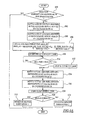
- FIG. 5A a method for determining degradation of a post-catalyst exhaust gas sensor in accordance with the present invention is illustrated.
- step 100 a determination is made as to whether to monitor exhaust gas sensors 64, 66 for degradation. For example, when engine 12 is in a low load operating condition or an idle operating condition, controller 58 may monitor sensors 64, 66. If the sensors 64, 66 are to be monitored, the method advances to step 102. Otherwise, the method is exited.
- an air-fuel mixture that is on average rich of stoichiometric represented by signal BIAS[1] is delivered to cylinder bank 16.
- signal BIAS[1] switches to a rich state indicating that a rich air-fuel mixture is being delivered to cylinder bank 16.
- step 104 an air-fuel mixture that is on average rich of stoichiometric, represented by signal BIAS[2], is delivered to cylinder bank 18.
- steps 102 and 104 are purging stored oxygen from catalytic converters 52, 53. Thereafter, the method advances to step 106.
- step 108 the method advances to step 108.
- step 110 a running delay timer DLY_TMR is started.
- step 110 a determination is made as to whether the value of DLY_TMR is greater than a max purge time MAX_PT. If the value of step 110 equals "No", the method re-executes step 110 which waits for the max purge time MAX_PT to elapse. Otherwise, the method advances to step 112 which stops and clears a running delay timer DLY_TMR.
- an air-fuel mixture that is on average lean of stoichiometric represented by signal BIAS[1] is delivered to cylinder bank 16.
- signal BIAS[1] the signal BIAS[2] switches to a lean state indicating a lean air-fuel mixture is being delivered to cylinder bank 16.
- step 116 an air-fuel mixture that is on average lean of stoichiometric, represented by signal BIAS[2], is delivered to cylinder bank 18.
- signal BIAS[2] switches to a lean state indicating that a lean air-fuel mixture is being delivered to cylinder bank 18.
- steps 114 and 116 are supplying oxygen to catalytic converters 52, 53, respectively, since by definition lean air-fuel mixtures result in un-combusted oxygen being expelled from cylinder banks 16, 18.
- step 120 a determination is made as to whether the signal BIAS[1] is not equal to the signal BIAS[2].
- the average fuel bias delivered to cylinder bank 16 may be equal to or different than the average fuel bias delivered to cylinder bank 18 depending on desired engine operating conditions.
- cylinder banks 16, 18 would be expelling an equivalent amount of oxygen to catalytic converters 52, 53, respectively.
- the amount of oxygen supplied to either of converters 52, 53 could be determined from value BIAS[1] or value BIAS[2].
- step 120 If the value of step 120 equals "Yes”, the step 122 executes the Monitor Sensor Subroutine1. Otherwise, the step 124 executes the Monitor Sensor Subroutine2.
- the Monitor Sensor Subroutinel is illustrated for determining whether post-catalyst exhaust gas sensors 64, 66 are degraded.
- the value O2_SUM[1] indicative of the amount of oxygen supplied to catalytic converter 52 is calculated utilizing Equation1 as discussed above.
- the value of O2_SUM[2] indicative of the amount of oxygen supplied to catalytic converter 53 is calculated utilizing Equation2 as discussed above.
- step 128 If the value of step 128 equals "Yes”, the subroutine is exited. Otherwise, the subroutine advances to step 129.
- step 129 a determination is made as to whether the signal REGO[1] was determined to be degraded in a prior iteration of the subroutine. If the value of step 129 equals "Yes", the subroutine advances to step 137 explained in detail below. Otherwise, the subroutine advances to step 130.
- step 132 the subroutine advances to step 137.
- step 130 if the value of the signal REGO[1] does not indicate a lean state, the subroutine advances to step 134.
- step 136 indicates that the signal REGO[1] is degraded. Otherwise, the subroutine advances to step 137.
- step 137 a determination is made as to whether the signal REGO[2] was determined to be degraded in a prior iteration of the subroutine. If the value of step 137 equals "Yes", the subroutine advances to step 146 explained in detail below. Otherwise, the subroutine advances to step 138.
- step 140 the subroutine advances to step 146 explained in detail below.
- step 142 a determination is made as to whether the value O2_SUM[2] is greater than or equal to the value O2_SUM_AVG[2]*C F ; where C f equals a constant value such as 1.1 for example.
- step 144 indicates that the signal REGO[2] is degraded. Referring to Figure 4E, for example, at time T 12 the signal O2_SUM[2] is determined to be degraded.
- step 144 if the value of step 144 equals "No, the subroutine advances to step 146.
- step 146 a determination is made as to whether the signals REGO[1] and REGO[2] have been determined to be degraded. If the value of step 146 equals "Yes", the subroutine is exited. Otherwise, the subroutine advances back to the step 126 for continued monitoring of the sensors 64, 66.
- the Monitor Sensor Subroutine2 is illustrated for determining whether post-catalyst exhaust gas sensors 64, 66 are degraded.
- the possible engine conditions where the subroutine can be advantageously utilized will be explained. Assume for example that pre-catalyst signal HEGO[2] is degraded. In this event, those skilled in the art will recognize that the signal HEGO[1] could be utilized to control the air-fuel delivery to cylinder bank 16 and cylinder bank 18. Further, an equal amount of lean fuel bias could be supplied to cylinder banks 16, 18, resulting in an equal amount of oxygen is being supplied to both catalytic converters 52, 53 during lean operation.
- the Monitor Sensor Subroutine2 described below can determine degradation of both post-catalyst sensors 64, 66 even if a pre-catalyst sensor, such as sensor 62, is degraded.
- the Monitor Sensor Subroutine 2 will now be explained.
- the value O2_SUM[1] indicative of the amount of oxygen supplied to catalytic converter 52 is calculated utilizing Equation1 as discussed above. It should be noted that the value O2_SUM[1] corresponds to the amount of oxygen delivered to both catalytic converters 52, 53 since the fuel bias delivered to cylinder banks 16, 18 are equal.
- step 150 a determination is made as to whether the value of lean timer L_TMR is greater than a maximum allowable time MAX_LEAN_TIME. If the value of step 150 equals "Yes", the subroutine is exited. Otherwise, the subroutine advances to step 152.
- step 152 a determination is made as to whether the signal REGO[1] was determined to be degraded in a prior iteration of the subroutine. If the value of step 152 equals "Yes", the subroutine advances to step 162 explained in detail below. Otherwise, the subroutine advances to step 154.
- step 156 the subroutine advances to step 162 explained in detail below.
- step 160 indicates that the signal REGO[1] is degraded. Otherwise, the subroutine advances to step 162.
- step 162 a determination is made as to whether the signal REGO[2] was determined to be degraded in a prior iteration of the subroutine. If the value of step 162 equals "Yes", the subroutine advances to step 172 explained in detail below. Otherwise, the subroutine advances to step 164.
- step 168 a determination is made as to whether the value O2_SUM[1] is greater than or equal to the value O2_SUM_AVG[2]*C F ; where C f equals a constant value such as 1.1 for example.
- step 170 indicates that the signal REGO[2] is degraded.
- the signal REGO[1] becomes degraded at time T 13 .
- the value of step 168 equals "No"
- the subroutine advances to step 172.
- step 172 a determination is made as to whether the signals REGO[1] and REGO[2] have been determined to be degraded. If the value of step 172 equals "Yes", the subroutine is exited. Otherwise, the subroutine advances back to the step 148.
- the system 14 and method for determining degradation of post-catalyst exhaust gas sensors in accordance with the present invention therefore provide a substantial advantage over conventional systems and methods.
- the system and method can accurately determine post-catalyst sensor degradation without assuming the post-catalyst sensors are non-degraded as done by known systems and methods.
Abstract
Description
- The invention relates to a system and method for determining the degradation of a sensor used in a motor vehicle and in particular to a method and system for determining the degradation of an exhaust gas sensor downstream of an exhaust catalyst.
- To meet current emission regulations, automotive vehicles must regulate the air-fuel ratio supplied to the engine cylinders of the vehicle to achieve maximum efficiency of exhaust gas catalysts. For this purpose, it is known to control the air-fuel ratio of internal combustion engines using an exhaust gas oxygen sensor positioned in the exhaust stream from the engine. The exhaust gas sensor provides feedback data to an electronic controller that calculates desired air-fuel ratio values over time to achieve optimum efficiency of a catalyst in the exhaust system. It is also known to have a system with two exhaust gas sensors in the exhaust stream in an effort to achieve more precise air-fuel ratio control with respect to a catalyst operational window. Normally, a pre-catalyst exhaust gas oxygen sensor is positioned upstream of the catalyst and a post-catalyst exhaust gas oxygen sensor is positioned downstream of the catalyst.
- In connection with an engine having two groups of cylinders, it is known to have a two-bank exhaust system coupled thereto where each exhaust bank has a catalyst as well as pre-catalyst and post-catalyst exhaust gas sensors. Each of the exhaust banks corresponds to a group of cylinders in the engine. The feedback signal received from the exhaust gas sensors are used to calculate the desired air-fuel values in their respective group of cylinders at any given time.
- Known engine control systems have also implemented strategies for determining when a pre-catalyst exhaust gas sensor becomes degraded. However, known engine control systems assume that post-catalyst exhaust gas sensors do not degrade since the sensors are buffered from a majority of the exhaust gases by the upstream catalyst. Thus, when a post-catalyst exhaust gas sensor does become degraded, an engine control system using a degraded output signal from the post-catalyst exhaust gas sensor will be unable to maintain optimal air-fuel values for optimal catalyst efficiency. Thus, the degraded post-catalyst exhaust gas sensor may result in increased emissions and decreased fuel economy.
- It is an object of the invention to provide a system and method to determine when a post-catalyst sensor becomes degraded.
- According to a first aspect of the invention there is provided a method for determining degradation of a first exhaust gas sensor utilized in an engine, the engine coupled to one or more catalysts characterised in that the method comprises generating a first signal from a first exhaust gas sensor disposed downstream of a first catalyst, determining an amount of oxygen supplied to one of the catalysts and determining degradation of the first exhaust gas sensor based on the amount of supplied oxygen and the first signal.
- The one of the catalysts may comprise the first catalyst and the first catalyst may communicate with a first cylinder bank of the engine.
- The step of determining the amount of supplied oxygen may include supplying an air-fuel mixture that is on average rich of stoichiometric to the first cylinder bank to remove oxygen stored in the first catalyst, supplying an air-fuel mixture that is on average lean of stoichiometric to the first cylinder bank and determining the amount of oxygen supplied to the first catalyst based on an amount of the average lean air-fuel mixture delivered to the first cylinder bank.
- The step of determining degradation of the first exhaust gas sensor may include comparing the amount of oxygen supplied to the first catalyst to a predetermined oxygen amount and indicating the first exhaust gas sensor is degraded when the amount of supplied oxygen is greater than the predetermined oxygen amount and the first signal does not indicate an air-fuel ratio lean of stoichiometric.
- The engine may includes a second cylinder bank coupled to a second catalyst, and a second exhaust gas sensor coupled downstream of the second catalyst generating a second signal and the method may further comprise determining an amount of oxygen supplied to the second catalyst and determining degradation of the second exhaust gas sensor based on the amount of oxygen supplied to the second catalyst and the second signal.
- The engine may include a second cylinder bank coupled to a second catalyst, and a second exhaust gas sensor coupled downstream of the second catalyst generating a second signal and the method further comprises determining degradation of the second exhaust gas sensor based on the amount of oxygen supplied to the first catalyst and the second signal.
- The step of determining an amount of oxygen supplied to the second catalyst may include supplying an air-fuel mixture that is on average rich of stoichiometric to the first and second cylinder banks to remove oxygen stored in the first and second catalysts, respectively, supplying an air-fuel mixture that is on average lean of stoichiometric to the first and second cylinder banks and calculating the amount of oxygen supplied to the second catalyst based on an amount of the average lean air-fuel mixture supplied to the second cylinder bank.
- The method may further include indicating when to monitor the first exhaust gas sensor for degradation.
- The engine may include a first cylinder bank coupled the first catalyst and a second cylinder bank coupled to a second catalyst and the one of the catalysts comprises the second catalyst.
- The step of determining degradation of the first exhaust gas sensor may include comparing the amount of oxygen supplied to the second catalyst to a predetermined oxygen amount and indicating the first exhaust gas sensor is degraded when the amount of oxygen supplied to the second catalyst is greater that the predetermined oxygen amount and the first signal does not indicate an air-fuel ratio lean of stoichiometric.
- According to a second aspect of the invention there is provided a system for determining degradation of an exhaust gas sensor utilized in an engine, the engine coupled to first and second catalysts characterised in that the system comprises a first exhaust gas sensor coupled downstream of the first catalyst generating a first signal and a controller operably coupled to the first exhaust gas sensor wherein the controller is configured to determine an amount of oxygen supplied to one of the first and second catalysts and is further configured to determine degradation of the first exhaust gas sensor based on the amount of supplied oxygen and the first signal.
- The first catalyst may be a three-way catalytic converter.
- The controller may be further configured to indicate when to monitor said first exhaust gas sensor for degradation.
- The controller may be further configured to compare said amount of oxygen supplied to said first catalyst to a predetermined oxygen amount, and to indicate said first exhaust gas sensor is degraded when said amount of oxygen supplied to said first catalyst is greater than said predetermined oxygen amount and said first signal does not indicate an air-fuel ratio lean of stoichiometric.
- The controller may be further configured to compare said amount of oxygen supplied to said second catalyst to a predetermined oxygen amount, and to indicate said first exhaust gas sensor is degraded when said amount of oxygen supplied to said second catalyst is greater than said predetermined oxygen amount and said first signal does not indicate an air-fuel ratio lean of stoichiometric.
- According to a third aspect of the invention there is provided an article of manufacture comprising a computer storage medium having a computer program encoded therein for determining degradation of a first exhaust gas sensor utilized in an engine, said engine coupled to first and second catalysts, said first exhaust gas sensor disposed downstream of said first catalyst generating a first signal, said computer storage medium comprising code for receiving said first signal from said first exhaust gas sensor, code for determining an amount of oxygen supplied to one of said first and second catalysts and code for determining degradation of said first exhaust gas sensor based on said amount of supplied oxygen and said first signal.
- The computer storage medium may further include code for comparing said amount of oxygen supplied to said first catalyst to a predetermined oxygen amount and code for indicating said first exhaust gas sensor is degraded when said amount of oxygen supplied to said first catalyst is greater than said predetermined oxygen amount and said first signal does not indicate an air-fuel ratio lean of stoichiometric.
- The computer storage medium may further include code for comparing said amount of oxygen supplied to said second catalyst to a predetermined oxygen amount and code for indicating said first exhaust gas sensor is degraded when said amount of oxygen supplied to said second catalyst is greater than said predetermined oxygen amount and said first signal does not indicate an air-fuel ratio lean of stoichiometric.
- According to a fourth aspect of the invention there is provided a motor vehicle having a system in accordance with said second aspect of the invention.
- The invention will now be described by way of example with reference to the accompanying drawing of which:-
- Figure 1 is block diagram of an automotive vehicle having an engine and an engine control system;
- Figure 2 is a block diagram the engine of Figure 1 illustrating dual exhaust banks;
- Figures 3A-3E are schematics of signals used to determine whether a post-catalyst exhaust gas sensor in a first exhaust bank is degraded;
- Figures 4A-4E are schematics of signals used to determine whether a post-catalyst exhaust gas sensor in a second exhaust bank is degraded; and
- Figures 5A-5C are flowcharts of a method of determining degradation of post-catalyst exhaust gas sensors in accordance with the present invention.
-
- Referring now to the drawings, like reference numerals are used to identify identical components in the various views. Referring to Figures 1 and 2, an
automotive vehicle 10 is shown that can be used to implement a method for determining sensor degradation in accordance with the present invention.Vehicle 10 includes aninternal combustion engine 12 and anengine control system 14. -
Engine 12 may comprise first andsecond cylinder banks first cylinder bank 16 for purposes of clarity. - The
engine 12 further includes acombustion chamber 30,cylinder walls 32, apiston 34, acrankshaft 35, aspark plug 36, anintake manifold 38,exhaust manifolds intake valve 42, anexhaust valve 44, athrottle body 46, athrottle plate 48, afuel injector 50, andcatalytic converters - The
combustion chamber 30 communicates withintake manifold 38 andexhaust manifold 40 via respective intake andexhaust valves combustion chamber 30 betweencylinder walls 32 and is connected tocrankshaft 35. Ignition of an air-fuel mixture withincombustion chamber 30 is controlled viaspark plug 36 which delivers ignition spark responsive to a signal fromdistributorless ignition system 54. -
Intake manifold 38 communicates withthrottle body 46 viathrottle plate 48.Throttle plate 48 is controlled byelectric motor 55 which receives a signal fromETC driver 56.ETC driver 56 receives a control signal (DC) from acontroller 58.Intake manifold 38 is also shown havingfuel injector 50 coupled thereto for delivering fuel in proportion to the pulse width of signals (FPW) fromcontroller 58. Fuel is delivered tofuel injector 50 by a conventional fuel system (not shown) including a fuel tank, fuel pump, and fuel rail (now shown). Although port fuel injection is shown, direct fuel injection could be utilized instead of port fuel injection. - Referring to Figure 2,
exhaust manifolds catalysts - The
catalysts -
Exhaust gas sensors catalysts exhaust gas sensors catalysts - The
exhaust gas sensors Sensors catalysts - The
sensors catalysts - Referring to Figure 1,
control system 14 is provided to control the operation ofengine 12 and to implement a method for monitoring post-catalyst exhaust gas sensors in accordance with the present invention.Control system 14 includesdistributorless ignition system 54, anelectric motor 55 for controlling thethrottle plate 48, anETC driver 56,exhaust gas sensors air flow sensor 68, atemperature sensor 70, athrottle position sensor 72, atorque sensor 74, anengine speed sensor 76, apedal position sensor 78, anaccelerator pedal 80, andcontroller 58. - Mass
air flow sensor 68 generates a signal indicating the inducted mass air flow (AM) that is transmitted tocontroller 58.Sensor 68 may be coupled to thethrottle body 46 orintake manifold 38. -
Temperature sensor 70 generates a signal indicating the engine coolant temperature (ECT) received bycontroller 58.Sensor 70 may be coupled to coolingjacket 71 incylinder wall 36. -
Throttle position sensor 72 generates a signal indicating a throttle position (TP) ofthrottle plate 48 received bycontroller 58 for closed-loop control ofplate 48. -
Torque sensor 74 generates a signal (TQ) that may indicate one of following torque values: (i) an engine crankshaft torque, ii) a transmission torque, such as for example, a torque converter turbine torque or a transmission output shaft torque, or (iii) an axle torque. -
Engine speed sensor 76 may comprise a Hall Effect sensor that generates a signal (N) indicating an engine speed. Thesensor 76 is coupled tocrankshaft 35 and transmits signal (N) tocontroller 58. -
Accelerator pedal 80 is shown communicating with a driver'sfoot 82.Pedal position sensor 78 generates a signal indicating acceleration pedal position (PP) that is transmitted tocontroller 58. - The
controller 58 is provided to implement the method for determining degradation of a post-catalyst exhaust gas sensor in accordance with the present invention. Thecontroller 58 includes amicroprocessor 84 communicating with various computer-readable storage media. - The computer readable storage media preferably include nonvolatile and volatile storage in a read-only memory (ROM) 86 and a random-access memory (RAM) 88. The computer readable media may be implemented using any of a number of known memory devices such as PROMs, EPROMs, EEPROMs, flash memory or any other electric, magnetic, optical or combination memory device capable of storing data, some of which represent executable instructions, used by
microprocessor 84 in controllingengine 12. - The
microprocessor 84 communicates with various sensors and actuators (discussed above) via an input/output (I/O)interface 90. Of course, the present invention could utilize more than one physical controller to provide engine/vehicle control depending upon the particular application. - The underlying theory for determining degradation of a post-catalyst exhaust gas sensor will now be discussed. The inventors herein have recognized that during the operational life of a catalyst such as a catalytic converter, the oxygen storage capacity can only decrease. In other words, the amount of oxygen stored by the catalyst will not increase during the operational life of the catalyst. Further, the inventors herein have developed a strategy for determining an amount of oxygen supplied to the catalyst during periods of lean air-fuel operation. Thus, when the amount of oxygen supplied to the catalyst is greater than an oxygen storage capacity of the catalyst and a post-catalyst exhaust gas sensor does not indicate a lean air-fuel state with respect to stoichiometric, the exhaust gas sensor is determined to be degraded.
- Referring to Figures 3A-3E, the signals utilized or generated by
controller 58 for determining degradation of a post-catalyst exhaust gas sensor will be discussed. - Referring to Figures 3A and 4A, the signals HEGO[1] and HEGO[2] are generated by
oxygen sensors cylinder banks - Referring to Figures 3B and 4B, the signals LAMBSE[1] and LAMBSE[2] are generated by the
controller 58 and are indicative of a desired air-fuel ratio forcylinder banks - Referring to Figures 3A and 3B, at time T0, the desired air-fuel ratio is steadily increased over time, becoming more leaner, until the
exhaust gas sensor 60 detects a lean air-fuel state in the exhaust gases. This portion of signal LAMBSE[1] is referred to as aramp portion 92 because the air-fuel ratio is being ramped up during this time period. - At time T1, when
sensor 60 detects the air-fuel ratio has switched to a lean state, LAMBSE[1] is abruptly dropped toward or past stoichiometric. This portion of signal LAMBSE[2] is referred to a jump-back portion 94. - Thereafter, signal LAMBSE[1] is steadily decreased, becoming more and more rich, until the air-fuel ratio reaches a particular rich threshold value at time T2. Similar to when the air-fuel ratio steadily increases, this portion of signal LAMBSE[1] is referred to as a
ramp portion 96. - At time T2, if an air-fuel ratio is desired that is on average rich of stoichiometric (i.e., a rich fuel bias), based on signal REGO{1] for example, the signal LAMBSE[1] is held (after the jump-back) at a predetermined level to deliver a desired level of rich fuel bias. As illustrated, between times T2-T3, the signal LAMBSE[1] is maintained at a rich level to deliver the desired amount of rich fuel bias.
- Similarly, if an air-fuel ratio is desired that is on average lean of stoichiometric (i.e., a lean fuel bias), based on signal REGO[1] for example, the signal LAMBSE[1] is held (after the jump-back) at a particular level to deliver a desired amount of lean fuel bias. As illustrated, between times T7-T8, the signal LAMBSE[1] is maintained at a lean level to deliver a desired amount of lean fuel bias. This portion of signal LAMBSE[1] is referred to a
hold portion 98. - Those skilled in the art will recognize that signals LAMBSE[1], LAMBSE[2] may be generated based on signals HEGO[1], HEGO[2], respectively and signals REGO[1], REGO[2], respectively, using one of a plurality of known methods. For example, the method disclosed in commonly assigned U.S. Patent No. 5,357,751 entitled "Air/Fuel Control System Providing Catalytic Monitoring" may be utilized to generate signals LAMBSE[1] and LAMBSE[2], which is incorporated herein in its entirety.
- Referring to Figures 3C and 4C, the fuel bias signals BIAS[1] and BIAS[2] are generated by
controller 58 and correspond to average air-fuel ratios delivered tocylinder banks - Similarly, the area between signal BIAS[1] and the stoichiometric reference line between times T6-T11, corresponds to the area between signal LAMBSE[1] and the stoichiometric reference line between times T7-T8 and times T10-T11.
- Referring to Figures 3D and 4D, the signals REGO[1] and REGO[2] generated by post-catalyst
exhaust gas sensors catalytic converter 52 is saturated with oxygen. In particular, the oxygen supplied to converter 52 (during delivery of a lean fuel bias) has completely saturated the oxygen storing elements (e.g., cerium) ofconverter 52. - Alternatively, when signal BIAS[1] indicates a rich air-fuel state, it is indicative that
catalytic converter 52 has completely reduced the oxygen in the oxygen storage elements ofconverter 52. - Referring to Figures 3E and 4E, the values O2_SUM[1] and O2_SUM[2] are calculated by
controller 58 and correspond to an amount of oxygen supplied tocatalytic converters cylinder banks - Where:
- BIAS[1] = (moles of oxygen / moles of exhaust gas)
delivered to
catalyst 52 during a lean fuel bias; - AM/2 = air mass flow rate (grams per second) delivered to cylinder bank 16 (and cylinder bank 18). It should be noted that it is assumed that an exhaust flow rate equals the air mass flow rate;
- KL = (molecular weight of oxygen / molecular weight of exhaust gas). That is to say KL = (32 grams of oxygen/mole)/(28.8 grams of exhaust/mole);
- ΔT = the time interval elapsed since the last value of O2_SUM[1] was calculated.
-
- Similarly, the value 02_SUM[2] may be calculated using the following integral Equation2:
- BIAS[2] = (moles of oxygen / moles of exhaust gas)
delivered to
catalyst 53 during a lean fuel bias. -
- Referring to Figures 3C and 3E, during delivery of a lean fuel bias between times T6-T11, the signal BIAS[1] may be integrated using Equation1 to obtain the value O2_SUM[1] corresponding to the amount of oxygen supplied to
catalytic converter 52. - Similarly, referring to Figures 4C and 4E, during delivery of a lean fuel bias between times T6-T11, the value of BIAS[2] may be integrated using Equation2 to obtain the value O2_SUM[2] corresponding to the amount of oxygen supplied to
catalytic converter 53. - Referring to Figure 5A, a method for determining degradation of a post-catalyst exhaust gas sensor in accordance with the present invention is illustrated.
- At
step 100, a determination is made as to whether to monitorexhaust gas sensors engine 12 is in a low load operating condition or an idle operating condition,controller 58 may monitorsensors sensors - At
step 102, an air-fuel mixture that is on average rich of stoichiometric, represented by signal BIAS[1], is delivered tocylinder bank 16. Referring to Figure 3C, for example, at time T0 the signal BIAS[1] switches to a rich state indicating that a rich air-fuel mixture is being delivered tocylinder bank 16. - Referring again to Figure 5A, at
step 104 an air-fuel mixture that is on average rich of stoichiometric, represented by signal BIAS[2], is delivered tocylinder bank 18. - Referring to Figure 4C, for example, at time T0 the signal BIAS[2] switches to a rich state indicating that a rich air-fuel mixture is being delivered to
cylinder bank 18. Thus, steps 102 and 104 are purging stored oxygen fromcatalytic converters - At
step 106, a max purge time MAX_PT needed to purgecatalytic converters - Where:
- BIAS[1] = (moles of fuel / moles of exhaust gas)
delivered to
catalyst 52 during a lean fuel bias; - BIAS[2] = (moles of fuel / moles of exhaust gas)
delivered to
catalyst 53 during a lean fuel bias; - O2_SUM_AVG[1] = an average maximum oxygen storage
amount for
catalytic converter 52; - O2_SUM_AVG[2] = an average maximum oxygen storage
amount for
catalytic converter 53; - KR = (molecular weight of oxygen / molecular weight of exhaust gas * number of grams of oxygen to burn one gram of fuel). For example, KR = (32 grams of oxygen/mole)/(28.8 grams of exhaust/mole) * (3.3 grams of oxygen/1 gram of fuel).
-
- Next, the method advances to step 108.
- Next at
step 108, a running delay timer DLY_TMR is started. Next, atstep 110, a determination is made as to whether the value of DLY_TMR is greater than a max purge time MAX_PT. If the value ofstep 110 equals "No", the methodre-executes step 110 which waits for the max purge time MAX_PT to elapse. Otherwise, the method advances to step 112 which stops and clears a running delay timer DLY_TMR. - Next at
step 114, an air-fuel mixture that is on average lean of stoichiometric, represented by signal BIAS[1], is delivered tocylinder bank 16. Referring to Figure 3C, for example, at time T6 the signal BIAS[2] switches to a lean state indicating a lean air-fuel mixture is being delivered tocylinder bank 16. - Referring again to Figure 5A, at
step 116 an air-fuel mixture that is on average lean of stoichiometric, represented by signal BIAS[2], is delivered tocylinder bank 18. Referring to Figure 4C, for example, at time T6 the signal BIAS[2] switches to a lean state indicating that a lean air-fuel mixture is being delivered tocylinder bank 18. Thus, steps 114 and 116 are supplying oxygen tocatalytic converters cylinder banks - Next at
step 120, a determination is made as to whether the signal BIAS[1] is not equal to the signal BIAS[2]. - Those skilled in the art will recognize that the average fuel bias delivered to
cylinder bank 16 may be equal to or different than the average fuel bias delivered tocylinder bank 18 depending on desired engine operating conditions. When the value BIAS[1] equals the value BIAS[2],cylinder banks catalytic converters converters - In contrast, when the value BIAS[1] is not equal to the value BIAS[2],
cylinder banks catalytic converters converters step 120 equals "Yes", thestep 122 executes the Monitor Sensor Subroutine1. Otherwise, thestep 124 executes the Monitor Sensor Subroutine2. - Referring to Figure 5B, the Monitor Sensor Subroutinel is illustrated for determining whether post-catalyst
exhaust gas sensors - At
step 126, the value O2_SUM[1] indicative of the amount of oxygen supplied tocatalytic converter 52 is calculated utilizing Equation1 as discussed above. Next atstep 127, the value of O2_SUM[2] indicative of the amount of oxygen supplied tocatalytic converter 53 is calculated utilizing Equation2 as discussed above. - At
step 128, a determination is made as to whether the value of lean timer L_TMR is greater than a maximum allowable time MAX_LEAN_TIME. The value MAX_LEAN_TIME may be calculated using the following equation: - Where:-
- If the value of
step 128 equals "Yes", the subroutine is exited. Otherwise, the subroutine advances to step 129. - At
step 129, a determination is made as to whether the signal REGO[1] was determined to be degraded in a prior iteration of the subroutine. If the value ofstep 129 equals "Yes", the subroutine advances to step 137 explained in detail below. Otherwise, the subroutine advances to step 130. - At
step 130, a determination is made as to whether the signal REGO[1] indicates a lean air-fuel state. If the value ofstep 130 equals "Yes", the subroutine advances to step 132 which calculates the value O2_SUM_AVG[1] using the following equation: - After
step 132, the subroutine advances to step 137. - Referring again to step 130, if the value of the signal REGO[1] does not indicate a lean state, the subroutine advances to step 134.
- At
step 134, a determination is made as to whether the value O2_SUM[1] is greater than or equal to the value O2_SUM_AVG[1]*CF
where Cf may, for example, equal a constant value within the range of 1.1-1.2. - If the value of
step 134 equals "Yes", thestep 136 indicates that the signal REGO[1] is degraded. Otherwise, the subroutine advances to step 137. - At
step 137, a determination is made as to whether the signal REGO[2] was determined to be degraded in a prior iteration of the subroutine. If the value ofstep 137 equals "Yes", the subroutine advances to step 146 explained in detail below. Otherwise, the subroutine advances to step 138. - At
step 138, a determination is made as to whether the signal REGO[2] indicates a lean air-fuel state. If the value ofstep 138 equals "Yes", the subroutine advances to step 140 which calculates the value O2_SUM_AVG[2] using the following equation: - After
step 140, the subroutine advances to step 146 explained in detail below. - Referring again to step 138, if the signal REGO[2] does not indicate a lean state, the subroutine advances to step 142. At
step 142, a determination is made as to whether the value O2_SUM[2] is greater than or equal to the value O2_SUM_AVG[2]*CF; where Cf equals a constant value such as 1.1 for example. - If the value of
step 142 equals "Yes", thestep 144 indicates that the signal REGO[2] is degraded. Referring to Figure 4E, for example, at time T12 the signal O2_SUM[2] is determined to be degraded. - Referring again to step 142, if the value of
step 144 equals "No, the subroutine advances to step 146. - At
step 146, a determination is made as to whether the signals REGO[1] and REGO[2] have been determined to be degraded. If the value ofstep 146 equals "Yes", the subroutine is exited. Otherwise, the subroutine advances back to thestep 126 for continued monitoring of thesensors - Referring to Figure 5C, the Monitor Sensor Subroutine2 is illustrated for determining whether post-catalyst
exhaust gas sensors
where the subroutine can be advantageously utilized will be explained. Assume for example that pre-catalyst signal HEGO[2] is degraded. In this event, those skilled in the art will recognize that the signal HEGO[1] could be utilized to control the air-fuel delivery tocylinder bank 16 andcylinder bank 18. Further, an equal amount of lean fuel bias could be supplied tocylinder banks catalytic converters - Thus, the inventors herein have recognized that an amount of oxygen supplied to
catalytic converter 52, for example, could be utilized to monitor bothexhaust gas sensors post-catalyst sensors sensor 62, is degraded. - Referring again to Figure 5C, the
Monitor Sensor Subroutine 2 will now be explained. Atstep 148, the value O2_SUM[1] indicative of the amount of oxygen supplied tocatalytic converter 52 is calculated utilizing Equation1 as discussed above. It should be noted that the value O2_SUM[1] corresponds to the amount of oxygen delivered to bothcatalytic converters cylinder banks - Next at
step 150, a determination is made as to whether the value of lean timer L_TMR is greater than a maximum allowable time MAX_LEAN_TIME. If the value ofstep 150 equals "Yes", the subroutine is exited. Otherwise, the subroutine advances to step 152. - At
step 152, a determination is made as to whether the signal REGO[1] was determined to be degraded in a prior iteration of the subroutine. If the value ofstep 152 equals "Yes", the subroutine advances to step 162 explained in detail below. Otherwise, the subroutine advances to step 154. - At
step 154, a determination is made as to whether the signal REGO[1] indicates a lean air-fuel state. If the value ofstep 154 equals "Yes", the subroutine advances to step 156 which calculates the value O2_SUM_AVG[1] using the following equation: - After
step 156 the subroutine advances to step 162 explained in detail below. - Referring again to step 154, if the value of the signal REGO[1] does not indicate a lean state, the subroutine advances to step 158. At
step 158, a determination is made as to whether the value O2_SUM[1] is greater than or equal to the value O2_SUM_AVG[1]*CF
where Cf = a constant value such as 1.1 for example. - If the value of
step 158 equals "Yes", thestep 160 indicates that the signal REGO[1] is degraded. Otherwise, the subroutine advances to step 162. - At
step 162, a determination is made as to whether the signal REGO[2] was determined to be degraded in a prior iteration of the subroutine. If the value ofstep 162 equals "Yes", the subroutine advances to step 172 explained in detail below. Otherwise, the subroutine advances to step 164. - At
step 164, a determination is made as to whether the signal REGO[2] indicates a lean air-fuel state. If the value ofstep 164 equals "Yes", the subroutine advances to step 166 which calculates the value O2_SUM_AVG[2] using the following equation:step 166, the subroutine advances to step 172 explained in detail below. - Referring again to step 164, if the signal REGO[2] does not indicate a lean state, the subroutine advances to step 168. At
step 168, a determination is made as to whether the value O2_SUM[1] is greater than or equal to the value O2_SUM_AVG[2]*CF; where Cf equals a constant value such as 1.1 for example. - If the value of
step 168 equals "Yes", thestep 170 indicates that the signal REGO[2] is degraded. - Referring again to Figure 3E and 4D, for example, at time T13, the signal O2_SUM[1] (shown as a dashed line) becomes greater than O2_SUM_AVG[2] (i.e., O2_SUM_AVG[2]= O2_SUM[1]*Cf) without the signal REGO[2] indicating a lean state. Thus, the signal REGO[1] becomes degraded at time T13. Referring again to Figure 5C, if the value of
step 168 equals "No", the subroutine advances to step 172. - At
step 172, a determination is made as to whether the signals REGO[1] and REGO[2] have been determined to be degraded. If the value ofstep 172 equals "Yes", the subroutine is exited. Otherwise, the subroutine advances back to thestep 148. - The
system 14 and method for determining degradation of post-catalyst exhaust gas sensors in accordance with the present invention therefore provide a substantial advantage over conventional systems and methods. In particular, the system and method can accurately determine post-catalyst sensor degradation without assuming the post-catalyst sensors are non-degraded as done by known systems and methods. - It will be appreciated by those skilled in the art that the embodiments described are presented by way of example and that various modifications or alternative embodiments could be constructed with departing from the scope of the invention.
Claims (9)
Applications Claiming Priority (2)
| Application Number | Priority Date | Filing Date | Title |
|---|---|---|---|
| US992949 | 1992-12-17 | ||
| US09/992,949 US6662638B2 (en) | 2001-11-26 | 2001-11-26 | System and method for determining degradation of an exhaust gas sensor in an engine |
Publications (2)
| Publication Number | Publication Date |
|---|---|
| EP1314868A1 true EP1314868A1 (en) | 2003-05-28 |
| EP1314868B1 EP1314868B1 (en) | 2005-06-01 |
Family
ID=25538920
Family Applications (1)
| Application Number | Title | Priority Date | Filing Date |
|---|---|---|---|
| EP02102620A Expired - Fee Related EP1314868B1 (en) | 2001-11-26 | 2002-11-21 | A Method and System for Determining the Degradation of an Exhaust Gas Sensor used in a Vehicle |
Country Status (3)
| Country | Link |
|---|---|
| US (1) | US6662638B2 (en) |
| EP (1) | EP1314868B1 (en) |
| DE (1) | DE60204414D1 (en) |
Cited By (2)
| Publication number | Priority date | Publication date | Assignee | Title |
|---|---|---|---|---|
| EP1734241A1 (en) * | 2005-06-17 | 2006-12-20 | Ford Global Technologies, LLC | Method for diagnosing a secondary lambda probe in a catalytic converter |
| DE10331334B4 (en) * | 2003-07-10 | 2012-12-20 | Volkswagen Ag | Method for operating an internal combustion engine |
Families Citing this family (12)
| Publication number | Priority date | Publication date | Assignee | Title |
|---|---|---|---|---|
| JP2004019542A (en) * | 2002-06-17 | 2004-01-22 | Toyota Motor Corp | Abnormality detector of oxygen sensor |
| DE102005034880B4 (en) * | 2005-07-26 | 2007-06-06 | Siemens Ag | Method and device for the diagnosis of an emission control system |
| JP4577160B2 (en) * | 2005-09-01 | 2010-11-10 | トヨタ自動車株式会社 | Exhaust gas sensor failure detection device |
| FR2906312B1 (en) * | 2006-09-27 | 2016-04-15 | Bosch Gmbh Robert | METHOD FOR DIAGNOSING AN EXHAUST GAS SENSOR EQUIPPED WITH AN INTERNAL COMBUSTION ENGINE AND DEVICE FOR CARRYING OUT SAID METHOD |
| DE102007006489B4 (en) * | 2007-02-09 | 2018-10-04 | Robert Bosch Gmbh | Method for diagnosing an exhaust gas sensor arranged in an exhaust region of an internal combustion engine and device for carrying out the method |
| US7523653B2 (en) * | 2007-06-14 | 2009-04-28 | Ford Gobal Technologies, Llc | Exhaust temperature sensor monitoring |
| JP2009221992A (en) * | 2008-03-17 | 2009-10-01 | Denso Corp | Malfunction diagnosing apparatus for exhaust gas sensor |
| DE102008046605B3 (en) * | 2008-09-10 | 2009-10-22 | Audi Ag | Oxygen accumulator's storage capacity checking method for use in internal combustion engine, involves deriving operability of probe and sufficiency and insufficiency of storage capacity of accumulator based on measuring values of probe |
| JP5024405B2 (en) * | 2010-03-09 | 2012-09-12 | トヨタ自動車株式会社 | Catalyst degradation detector |
| KR101305632B1 (en) * | 2011-09-21 | 2013-09-09 | 기아자동차주식회사 | System and method for detecting pollution by toxic substance for air exhauster of vehicle |
| DE102019100577B3 (en) | 2019-01-11 | 2019-12-19 | Bayerische Motoren Werke Aktiengesellschaft | Process for monitoring sensor signals and quantitative determination of the stoichiometric air-fuel ratio of the fuel used by means of an injector test and catalyst diagnosis in a vehicle |
| US11022061B1 (en) * | 2020-01-31 | 2021-06-01 | Ford Global Technologies, Llc | Systems and methods for an exhaust gas temperature sensor diagnostics using split lambda engine operation |
Citations (5)
| Publication number | Priority date | Publication date | Assignee | Title |
|---|---|---|---|---|
| US5533332A (en) * | 1993-09-02 | 1996-07-09 | Unisia Jecs Corporation | Method and apparatus for self diagnosis of an internal combustion engine |
| US5966930A (en) * | 1996-08-22 | 1999-10-19 | Honda Giken Kogyo Kabushiki Kaisha | Catalyst deterioration-determining system for internal combustion engines |
| EP1118758A2 (en) * | 2000-01-20 | 2001-07-25 | Ford Global Technologies, Inc. | Method and system for compensating for degraded pre-catalyst oxygen sensor in a two-bank exhaust system |
| US20010010220A1 (en) * | 2000-01-31 | 2001-08-02 | Honda Giken Kogyo Kabushiki Kaisha | Apparatus for determining a failure of an oxygen concentration sensor |
| EP1134378A2 (en) * | 2000-03-17 | 2001-09-19 | Ford Global Technologies, Inc. | Method for determining emission control system operability |
Family Cites Families (1)
| Publication number | Priority date | Publication date | Assignee | Title |
|---|---|---|---|---|
| US5781878A (en) * | 1995-06-05 | 1998-07-14 | Nippondenso Co., Ltd. | Apparatus and method for diagnosing degradation or malfunction of oxygen sensor |
-
2001
- 2001-11-26 US US09/992,949 patent/US6662638B2/en not_active Expired - Lifetime
-
2002
- 2002-11-21 EP EP02102620A patent/EP1314868B1/en not_active Expired - Fee Related
- 2002-11-21 DE DE60204414T patent/DE60204414D1/en not_active Expired - Lifetime
Patent Citations (5)
| Publication number | Priority date | Publication date | Assignee | Title |
|---|---|---|---|---|
| US5533332A (en) * | 1993-09-02 | 1996-07-09 | Unisia Jecs Corporation | Method and apparatus for self diagnosis of an internal combustion engine |
| US5966930A (en) * | 1996-08-22 | 1999-10-19 | Honda Giken Kogyo Kabushiki Kaisha | Catalyst deterioration-determining system for internal combustion engines |
| EP1118758A2 (en) * | 2000-01-20 | 2001-07-25 | Ford Global Technologies, Inc. | Method and system for compensating for degraded pre-catalyst oxygen sensor in a two-bank exhaust system |
| US20010010220A1 (en) * | 2000-01-31 | 2001-08-02 | Honda Giken Kogyo Kabushiki Kaisha | Apparatus for determining a failure of an oxygen concentration sensor |
| EP1134378A2 (en) * | 2000-03-17 | 2001-09-19 | Ford Global Technologies, Inc. | Method for determining emission control system operability |
Cited By (2)
| Publication number | Priority date | Publication date | Assignee | Title |
|---|---|---|---|---|
| DE10331334B4 (en) * | 2003-07-10 | 2012-12-20 | Volkswagen Ag | Method for operating an internal combustion engine |
| EP1734241A1 (en) * | 2005-06-17 | 2006-12-20 | Ford Global Technologies, LLC | Method for diagnosing a secondary lambda probe in a catalytic converter |
Also Published As
| Publication number | Publication date |
|---|---|
| DE60204414D1 (en) | 2005-07-07 |
| US20030097873A1 (en) | 2003-05-29 |
| EP1314868B1 (en) | 2005-06-01 |
| US6662638B2 (en) | 2003-12-16 |
Similar Documents
| Publication | Publication Date | Title |
|---|---|---|
| US6289672B1 (en) | Exhaust gas purification device for an internal combustion engine | |
| US6758185B2 (en) | Method to improve fuel economy in lean burn engines with variable-displacement-like characteristics | |
| US6725830B2 (en) | Method for split ignition timing for idle speed control of an engine | |
| US6736121B2 (en) | Method for air-fuel ratio sensor diagnosis | |
| US6736120B2 (en) | Method and system of adaptive learning for engine exhaust gas sensors | |
| US6735938B2 (en) | Method to control transitions between modes of operation of an engine | |
| US6453663B1 (en) | NOx sensor monitoring | |
| EP1314868B1 (en) | A Method and System for Determining the Degradation of an Exhaust Gas Sensor used in a Vehicle | |
| GB2390041A (en) | A method for controlling the temperature of an emission control device | |
| GB2391081A (en) | Controlling transition of IC engine between operating modes to provide rapid heating of emission control device | |
| US20130226437A1 (en) | Air-fuel ratio variation abnormality detecting device and air-fuel ratio variation abnormality detecting method | |
| US6761024B2 (en) | Air-fuel ratio control system and method for internal combustion engines | |
| US6684869B2 (en) | System and method for detecting an air leak in an engine | |
| EP1314869B1 (en) | A method and system for monitoring an exhaust gas sensor | |
| US6901327B2 (en) | Computer instructions for control of multi-path exhaust system in an engine | |
| EP1327756B1 (en) | A system and method for detecting an air leak in the exhaust system of an internal combustion engine | |
| EP1118758A2 (en) | Method and system for compensating for degraded pre-catalyst oxygen sensor in a two-bank exhaust system | |
| EP1074706B1 (en) | Temperature control method for a direct injection engine | |
| EP1074726A2 (en) | Engine control with a fuel vapour purge system | |
| US6354077B1 (en) | Method and system for controlling air/fuel level in two-bank exhaust system | |
| EP1074725B1 (en) | Control method for an engine with multiple emission control devices | |
| JP2011001833A (en) | Catalyst abnormality diagnostic device | |
| EP1087118A2 (en) | Heat generation method in an emission control device | |
| JP2021139340A (en) | Internal combustion engine control device | |
| GB2378668A (en) | A method and system for monitoring the efficiency of an exhaust gas treatment device |
Legal Events
| Date | Code | Title | Description |
|---|---|---|---|
| PUAI | Public reference made under article 153(3) epc to a published international application that has entered the european phase |
Free format text: ORIGINAL CODE: 0009012 |
|
| AK | Designated contracting states |
Designated state(s): AT BE BG CH CY CZ DE DK EE ES FI FR GB GR IE IT LI LU MC NL PT SE SK TR |
|
| AX | Request for extension of the european patent |
Extension state: AL LT LV MK RO SI |
|
| 17P | Request for examination filed |
Effective date: 20031106 |
|
| 17Q | First examination report despatched |
Effective date: 20031222 |
|
| AKX | Designation fees paid |
Designated state(s): DE GB |
|
| GRAP | Despatch of communication of intention to grant a patent |
Free format text: ORIGINAL CODE: EPIDOSNIGR1 |
|
| GRAS | Grant fee paid |
Free format text: ORIGINAL CODE: EPIDOSNIGR3 |
|
| GRAA | (expected) grant |
Free format text: ORIGINAL CODE: 0009210 |
|
| AK | Designated contracting states |
Kind code of ref document: B1 Designated state(s): DE GB |
|
| REG | Reference to a national code |
Ref country code: GB Ref legal event code: FG4D |
|
| REG | Reference to a national code |
Ref country code: GB Ref legal event code: 732E |
|
| REF | Corresponds to: |
Ref document number: 60204414 Country of ref document: DE Date of ref document: 20050707 Kind code of ref document: P |
|
| PG25 | Lapsed in a contracting state [announced via postgrant information from national office to epo] |
Ref country code: DE Free format text: LAPSE BECAUSE OF FAILURE TO SUBMIT A TRANSLATION OF THE DESCRIPTION OR TO PAY THE FEE WITHIN THE PRESCRIBED TIME-LIMIT Effective date: 20050902 |
|
| PLBE | No opposition filed within time limit |
Free format text: ORIGINAL CODE: 0009261 |
|
| STAA | Information on the status of an ep patent application or granted ep patent |
Free format text: STATUS: NO OPPOSITION FILED WITHIN TIME LIMIT |
|
| 26N | No opposition filed |
Effective date: 20060302 |
|
| REG | Reference to a national code |
Ref country code: GB Ref legal event code: 746 Effective date: 20080731 |
|
| PGFP | Annual fee paid to national office [announced via postgrant information from national office to epo] |
Ref country code: GB Payment date: 20191029 Year of fee payment: 18 |
|
| GBPC | Gb: european patent ceased through non-payment of renewal fee |
Effective date: 20201121 |
|
| PG25 | Lapsed in a contracting state [announced via postgrant information from national office to epo] |
Ref country code: GB Free format text: LAPSE BECAUSE OF NON-PAYMENT OF DUE FEES Effective date: 20201121 |