EP1313180A2 - An electrical connection for a power tool - Google Patents
An electrical connection for a power tool Download PDFInfo
- Publication number
- EP1313180A2 EP1313180A2 EP02024799A EP02024799A EP1313180A2 EP 1313180 A2 EP1313180 A2 EP 1313180A2 EP 02024799 A EP02024799 A EP 02024799A EP 02024799 A EP02024799 A EP 02024799A EP 1313180 A2 EP1313180 A2 EP 1313180A2
- Authority
- EP
- European Patent Office
- Prior art keywords
- handle
- power tool
- aperture
- axis
- tool
- Prior art date
- Legal status (The legal status is an assumption and is not a legal conclusion. Google has not performed a legal analysis and makes no representation as to the accuracy of the status listed.)
- Granted
Links
Images


Classifications
-
- H—ELECTRICITY
- H01—ELECTRIC ELEMENTS
- H01R—ELECTRICALLY-CONDUCTIVE CONNECTIONS; STRUCTURAL ASSOCIATIONS OF A PLURALITY OF MUTUALLY-INSULATED ELECTRICAL CONNECTING ELEMENTS; COUPLING DEVICES; CURRENT COLLECTORS
- H01R35/00—Flexible or turnable line connectors, i.e. the rotation angle being limited
- H01R35/02—Flexible line connectors without frictional contact members
Definitions
- the present invention relates to power tools and, in particular, to electric drills comprising a handle and a pivotable drill head having an electrical connection between the handle and the drill head.
- FIG. 1 This drill-driver comprises a body having a drill head portion and a handle portion fixed at approximately right-angle to the drill head portion.
- the drill head portion encapsulates an electric motor and a gearbox and the handle portion defines a conventional pistol grip to be grasped by the user.
- the handle portion comprises a variable speed trigger switch for low-speed rotary output in screw driving mode or high-speed rotary output in drilling mode.
- Conventional electrical wires make the electrical connection between the trigger switch in the handle portion and the motor in the head portion.
- the electrical wires are housed safely within the body and may be copper wires insulated in a plastic sheath.
- This drill-driver is well suited to drilling and screw driving, provided that the workpiece is easily accessible. However, if the hole to be drilled, or the screw to be fastened, is in a tight comer or an awkward position then this drill-driver, like a conventional electric drill, cannot gain access. In this case the user will need to resort to a smaller hand operated drill or a hand held screwdriver perform the task in hand.
- German Utility Model 8505814.9 discloses an electric drill having a drill head and a handle.
- the drill head comprises an electric motor coupled to a gearbox.
- the gearbox includes a rotary output protruding from the front end of the drill head.
- the handle comprises an on/off trigger switch and a battery pack.
- a flange extension attached to the rear end of the drill head is pivotally coupled to the top end of the handle.
- the drill head can be pivotally adjusted with respect to the handle through an arc of 90°, between a position where the drill head is perpendicular to the handle and another position where the drill head is in-line with the handle.
- the drill-driver disclosed by German Utility Model 8505814.9 is able to access work pieces inaccessible to a conventional drill-driver with pistol grip, like that shown in Figure 1.
- the pivotal rotation between the drill head and the handle produces a new problem of how to provide a simple and effective electrical connection between the drill head and the handle.
- a power tool comprising a handle and a tool body pivotally coupled to the handle by a pivot, characterised in that an electrical connection between the handle and the tool body passes through the pivot.
- the electrical connection may be, for example, by metal strips in frictional contact with metal slip rings or by conventional electric wires.
- the pivot may be any one of a range of known pivot mechanisms like, for example, a hinge, a spindle supported by ball bearings or a hub supported by a yoke, provided the pivot has enough space to accommodate the electrical connection.
- the pivot is a convenient location for the passage of the electrical connection from the handle to the tool body because the pivot is an existing link between the handle and the tool body. This obviates the need of an additional link between the handle and the tool head to accommodate the electrical connection.
- the pivot has a first axis and a connection aperture substantially concentric with the first axis, wherein the electrical connection passes though the connection aperture.
- a connection aperture located substantially concentric with the first axis of the pivot provides a convenient passage for the electrical connection because relative movement between the pivoting drill head and handle is minimal at the axis of the pivot.
- the electrical connection comprises two electrical wires.
- Electrical wires have the advantage of being more flexible than metal strips and therefore less liable to breakage, and are insulated.
- Location of the connection aperture in the first hub is concentric with the first axis which has the advantage that the wires are only lightly twisted as the tool head pivots relative to the handle and, as such, the wires are not subject to significant wear and tear.
- Using wires to electrically couple the components located in the handle with those located in the tool head obviates the need to implement the more elaborate and expensive solution of using metal strips with metal slip rings at the pivot.
- this gap should be sealed in order to shield the internal components of the tool body from ingress of dust and dirt.
- the pivot comprises at least one circular aperture formed in one of the tool body or the handle and at least one cylindrical hub protruding from the other of the tool body or the handle, wherein the at least one aperture has the first axis.
- the at least one hub is disposed concentrically within a respective aperture.
- the outer diameter of the at least one hub is slightly smaller than the diameter of a respective aperture to allow for sliding contact therebetween. Sliding contact between the at least one hub and a respective aperture supports the tool head for pivotal rotation relative to the handle.
- the at least one aperture is formed in the handle and the at least one hub is disposed upon the tool body.
- the number of holes in the tool body is reduced. This reduces the locations where dust and dirt may enter the interior of the tool body and interfere with the components, such as the motor, enclosed therein. Minimising the number of holes formed in the tool body has the advantage of increasing shielding of the interior components.
- the at least one aperture comprises a first aperture and a second aperture wherein the first aperture and the second aperture each have the first axis
- the at least one hub comprises a first hub disposed within the first aperture and a second hub disposed within the second aperture.
- the pivot comprises two hub and aperture arrangements, one of each arrangement disposed on diametrically opposite sides of the tool head to provide additional strength and rigidity to the pivotal support of the tool head.
- the connection aperture is in the first hub.
- the tool body is elongate and has a second axis perpendicular to the first axis and the power tool comprises a motor coupled to a rotary output, wherein the rotary output has the second axis.
- the rotary output conveniently protrudes from one of the ends of the elongate tool body.
- the motor is housed in the tool body, rather than the handle. This avoids the need for a complex mechanical coupling between the motor located in the handle and the rotary output located in the tool body.
- the power tool further comprises a power source for energising the motor and an electrical switch electrically coupled to the power source, wherein the switch is disposed upon the handle and the electrical connection carries electrical current from the switch to the motor housed in the tool body.
- the user can hold the power tool by the handle with one hand and operate the switch at the same time.
- the power source is preferably a battery pack.
- the battery pack may be housed within the handle or detachably connected to the handle.
- a battery pack housed within the handle may be electrically coupled to an electrical socket disposed upon the handle.
- the electrical socket connects the battery pack to an external battery charging source.
- the handle may be elongate and has a third axis.
- the third axis is perpendicular to the first axis.
- An arc defined by pivotal rotation of the tool head relative to the handle about the first axis subtends a pivotal angle between the second axis and the third axis. If the pivotal angle is limited to 90° then the tool head can only pivot between two operating positions located at right angle to each other, like, for example:
- orientation of the drill head relative to the handle need not be limited to operating positions i), ii) and iii) above when pivoting within a pivotal angle range of 180°, or any other pivotal angle range, and may also include one or more other positions.
- the pivotal angle may vary between 90° and 270° such that the tool head is perpendicular to the handle in positions i) and iii) above.
- the power tool preferably comprises a locking mechanism for locking the tool body against pivotal movement relative to the handle.
- the locking mechanism can be released to allow pivotal movement of the tool head relative to the handle when the user wishes to change the orientation of the tool head in preparation for a different task. After changing the orientation of the tool head, the user can lock the tool body in its new position by operating the locking mechanism.
- many different and suitable types of locking mechanism are readily available like, for example, a simple nut and bolt arrangement or a magnetic lock.
- a power tool shown generally as (2) is a drill-driver comprising a substantially cylindrical drill head (4) having a longitudinal axis X and an elongate handle (6) arranged about a longitudinal axis Y.
- the drill head (4) is pivotally mounted upon the handle (6) and pivots relative to the handle (6) about an axis Z.
- the handle (6) is formed by a first clamshell (8) and a second clamshell (10) which are joined together by a plurality of screws (not shown).
- the drill head (4) is formed by a third clamshell (12) and a fourth clamshell (14) which are joined together by a plurality of screws (not shown).
- the drill head (4) comprises an electric motor (16) and a transmission gearbox (not shown) with an output spindle (20).
- the motor (16) and the gearbox are housed inside the drill head (4).
- the front end of the drill head (4) comprises a cylindrical gear casing (22) surrounding the gearbox and the output spindle (20).
- the motor (16) is rotatingly coupled to the gearbox such that rotary motion of the motor (16) is transferred to the output spindle (20) via the gearbox.
- the end portion of the output spindle (20) has a hex drive coupling (24) attached thereto.
- the output spindle (20) and the coupling (24) protrude through a hole (26) in the gear casing (22).
- the output spindle (20) and the coupling (24) rotate about the axis (x).
- the coupling (24) releasably connects the output spindle (20) to a tool (28) having a conventional hexagonal shank arrangement.
- a conventional chuck can be attached to the end portion of the output spindle (20) for connection to a tool (28).
- the handle (8) comprises a button (30) fixed to a variable speed electrical switch (32).
- the switch (32) is electrically coupled to a power source (34).
- the switch (32) is also electrically coupled to the motor (16) by two electrical wires (36,38).
- the switch (32) is thermally coupled to a heat sink (39) located inside the handle (6).
- the heat sink (39) is for dissipating excess heat energy created by the internal components of the switch (32).
- the switch (32) is biased into an OFF position wherein the switch (32) interrupts electrical connection between the power source (38) and the motor (16) such that the motor (16) is denergised and the output spindle (20) does not rotate.
- Depression of the button (30) moves the switch (32) to an ON position wherein the switch (32) makes electrical connection between the power source (34) and the motor (16).
- the motor (20) is energised by the electrical current from the power source (34) and the output spindle (20) starts to rotate. Electrical current flowing from the power source (34) to the motor (16) is thus controlled by the switch (32) and is proportional to how far the button (30) is depressed.
- the switch (32) increases so does flow of electrical current to the motor (16) causing a corresponding increase in the rotational speed of the output spindle (20), and vice versa.
- the switch (32) returns to the OFF position to interrupt the electrical connection between the power source (34) and the motor (16) thus causing denergision of the motor (16).
- the handle (6) comprises a direction selector (40) for selecting the rotational direction of the motor (16) and the output spindle (20).
- the direction selector (40) is approximately T-shaped and comprises a forward button (42) on one side, a reverse button (44) on the other side, and a flange (46) in the middle.
- the forward (42) and reverse (44) buttons partially protrude through an aperture in each of the first (8) and second (10) clamshells respectively.
- the handle also comprises a barrel (48) with an upper flange (50), a lower flange (52) and a central cylinder (54) located between the upper and lower flanges (52,54).
- the barrel's flanges (50,52) each have a mainly circular circumference part which is interrupted by a protruding part and are shaped like a tear-drop.
- the circular part of upper and lower flanges (50,52) has a diameter greater than the central cylinder (54).
- the protruding part of the upper flange (50) has an upper spigot (56).
- the protruding part of the lower flange (54) has a lower spigot (58).
- the upper and lower spigots (56,58) are eccentric with respect the axis of the central cylinder (54) and point axially away from the central cylinder (54).
- the barrel (48) is supported for pivotal rotation by a pair of brackets (60,62) which are moulded into interior of the handle's clamshells (8,10).
- the brackets (60,62) surround the central cylinder (54) to support the barrel (48) against lateral movement.
- the brackets (60,62) abut the inner faces of the upper and lower flanges (50,52) to support the barrel (48) against axial movement.
- the handle (6) further comprises an arm (64) with a hollow cylindrical hub (66) at one end and a finger (68) at the other end.
- the arm (64) is pivotally coupled to the internal components of the switch (32) at a point midway between the hub (66) and the finger (68).
- the arm (64) can pivot between a forward position, a central position and a reverse position. Pivotal movement of the arm (64) from its forward position to its reverse position, and vice versa, causes the switch (32) to change the polarity of the electrical wires (36,38), as explained in more detail below.
- the direction selector (40) is mechanically coupled to the switch (32) via the barrel (48) and the arm (64) in the following manner.
- the barrel's upper spigot (56) engages the direction selector (40) by protruding through a hole in the flange (46).
- the barrel's lower spigot (58) is seated within the arm's hollow cylindrical hub (66) in the manner of a trunnion arrangement.
- depression of the forward button (42) slides the direction selector (40) and the upper spigot (56) in one direction thereby rotating the barrel (48) about its axis.
- Rotation of the barrel (48) moves the lower spigot (58) in the opposite direction thereby pivoting the arm (64) into its forward position.
- Depression of the reverse button (44) reverses this sequence and causes the arm (64) to pivot from its forward position to its reverse position.
- the direction selector's buttons (42,44) are arrow-head shaped.
- the apex of the forward button (42) points forward to give the user a visual and tangible indication that depression of the forward button (42) causes the output spindle (20) to rotate in a clockwise direction (i.e. the rotational direction causing a screw or drill bit to be driven "forward" into a work piece) when the switch (32) is in the ON position.
- the apex of the reverse button (44) points backward to give the user a visual and tangible indication that depression of the reverse button (42) causes the output spindle (20) to rotate in an anti-clockwise direction when the switch (32) is in the ON position.
- the power source is a rechargeable battery pack (34) housed inside the bottom of the handle (6). To improve the electrical charge of the battery pack (34), thereby increasing operating life, the battery pack (34) is relatively bulky causing the handle (6) to protrude on the side of the switch button (30).
- the battery pack (34) is electrically coupled to a battery recharger socket (72) located at the lower end of the handle (6).
- the battery recharger socket (72) protrudes through a small aperture (74) in the handle (6) to provide an electrical link between the battery pack (34) and an external battery recharging source (not shown).
- the power source may be a rechargeable battery detachably fixed to the handle (6), or a mains electrical supply.
- the drill head (4) has a first cylindrical hub (76) and a second cylindrical hub (78) both located part way along the length of the drill head (4), remote from the output spindle (20).
- the first and second hubs (76,78) are located on opposite sides of the drill head (4).
- the first and second hubs (76, 78) are substantially the same diameter and both arranged about axis Z.
- the first and second hubs (76, 78) extend from the drill head (4) in diametrically opposed directions along axis Z.
- Axis Z is perpendicular to axis's X and Y.
- the first cylindrical hub (76) is moulded into the third clam shell (12) of the drill head (4).
- the first cylindrical hub (76) comprises a central inner aperture (80) co-axial with axis Z.
- the inner aperture (80) provides an entry point to the interior of the drill head (4).
- the second hub (78) comprises a circular toothed wheel (82), a protrusion (86) and, a cylindrical spigot (84) having axis Z.
- the protrusion (86) and the spigot (84) are moulded into the fourth clam shell (14) of the drill head (4).
- the wheel (82) comprises a central aperture (88) and a plurality of teeth (90) arranged equi-angularly around the circumference of the wheel (82).
- the toothed wheel (82) has eight teeth'(90) juxtaposed by eight recesses (92) for engagement with part of a locking plate, which is described in more detail below.
- the eight teeth (90) are arranged at 45° intervals about the axis Z.
- the wheel (82) is press fitted upon the fourth clam shell (14). Two of the eight teeth (90) are shorter than the outer diameter of the wheel (82).
- the protrusion (86) has a curved exterior face (94) and an interior face (96) shaped to surround the two short teeth (90) and engage three recesses (92a, 92b, 92c) adjacent the two short teeth (90) thereby preventing rotation of the wheel (82) relative to the drill head (4).
- the spigot (84) protrudes through the aperture (88).
- the outer diameter of the spigot (84) is slightly larger that the diameter of the aperture (88) such that interference fit between the spigot (84) and the circumference of the aperture (88) holds the wheel (82) upon the drill head (4).
- the curved exterior face (94) of the protrusion (86) and the tips of the teeth (90) collectively describe the outer circumference of the second hub (78).
- the wheel (82) is made of steel, Alternatively, the wheel (82) may be made of another suitable hard material.
- first supporting bracket (98) and a second supporting bracket (100) each shaped to nest in the interior of the first and the second clamshells (8,10) of the handle (6), respectively.
- the first bracket (98) has a circular aperture (102) for receiving the first hub (76).
- the second bracket (100) has a circular aperture (104) for receiving the second hub (76).
- the first and second hubs (76,78), the first and second bracket apertures (102,104), the first hub aperture (80) and the spigot (84) are co-axial having axis Z.
- the first and second bracket apertures (102,104) act as a yoke in which the first and second hubs (76,78) are supported for pivotal rotation relative to the handle (6). As such, the first and second bracket apertures (102,104) provide pivotal support to the first and second hubs (76,78), respectively, to allow the drill head (4) to pivot relative the handle (6) about axis Z.
- the first support bracket (98) has a first walled recess (106) facing the interior of the first clam shell (8) of the handle (6).
- the cavity (108) provides a connecting passageway from the interior of the handle (6) to first hub (76) for the wires (36,38). Accordingly, the wires (36,38) travel from the switch (32) via the cavity (108) through the first hub's aperture (80) to the motor (20) inside the drill head (4).
- the second support bracket (100) has a second walled recess (110) facing the interior of the first clam shell (10) of the handle (6).
- a space (112) bounded by the second walled recess (110) and the interior of the second clam shell (10) is formed therebetween.
- the space (112) contains a locking plate (114), a lock release button (116) fixed to the locking plate (114), and two helical springs (118).
- the locking plate (114) has a tongue (120) which is for locking engagement with any one of the five recesses (92d to 92h) of the toothed wheel (82) not occupied by the interior face (96) of the protrusion (86).
- the locking plate (114), the lock release button (116), and the two helical springs (118) collectively form a locking mechanism for locking pivotal movement of the head (4) relative to the handle (6) about the axis Z.
- the tongue (120) of the locking plate (114) is biased into engagement with a recess (92) by the springs (118), thereby locking pivotal movement of the head (4) relative to the handle (6).
- the user disengages the tongue (120) from a recess (92) by sliding the locking plate (114) and the release button (116) against the bias of the springs (118). Sliding movement of the locking plate (114) is guided by the second walled recess (110).
- Access to the release button (116) for operation of the locking plate (114) is provided by a hole (122) in the top end of the second clamshell (10) of the handle (6).
- axis Z is the axis about which the head (4) pivots with respect to the handle (6).
- Axis Y represents the position of the handle (6) and axis X represents the position of the drill head (4). Both axis X and Y remain perpendicular to axis Z regardless of the orientation of the drill head (4) in relation to the handle (8).
- the included angle between axis X and Y is referred to as angle ⁇ . Only angle ⁇ varies when the drill head (4) changes its orientation in relation to the handle (8) by pivoting about the axis Z. Angle ⁇ is dictated by which one of the five unoccupied recesses (92d to 92h) engages the tongue (120) of the locking plate (114).
- Angle ⁇ is 90° when recess (92d) engages the tongue (120), as shown in Figure 13.
- Recess (92e) is located 45° anti-clockwise from recess (92d), therefore angle ⁇ is 135° when recess (92e) engages the tongue (120), as shown in Figure11.
- Angle ⁇ is 180°, 225° and 270° when one of the three respective subsequent recesses (92f, 92g, 92h) engage the tongue (120).
- angle ⁇ can be set to five positions within a range of 180°, according to which one of the five unoccupied recesses (92d to 92h) engages the locking plate (114).
- the range of angle ⁇ can be increased from 180° by reducing the number of recesses (92) engaged by the interior face (96) of the protrusion (86) from three recesses (92a, 92b, 92c) to two recesses, or even only one recess.
- the number of positions within the range of angle ⁇ can be varied by changing the number of recesses (92) and teeth (90), or varying the angular spacing between adjacent recesses (92) and teeth (90) around the circumference of the toothed wheel (82).
Landscapes
- Drilling And Boring (AREA)
- Processing Of Terminals (AREA)
- Scissors And Nippers (AREA)
- Portable Power Tools In General (AREA)
Abstract
Description
- The present invention relates to power tools and, in particular, to electric drills comprising a handle and a pivotable drill head having an electrical connection between the handle and the drill head.
- Electric drills and electric screwdrivers are well known in the art. Attempts have been made to combine an electric drill with an electric screwdriver, resulting in a power tool resembling a conventional electric drill with added features to enable slow and controlled screw driving speeds. One such power tool, referred to as a drill-driver, is shown in Figure 1. This drill-driver comprises a body having a drill head portion and a handle portion fixed at approximately right-angle to the drill head portion. The drill head portion encapsulates an electric motor and a gearbox and the handle portion defines a conventional pistol grip to be grasped by the user. The handle portion comprises a variable speed trigger switch for low-speed rotary output in screw driving mode or high-speed rotary output in drilling mode. Conventional electrical wires make the electrical connection between the trigger switch in the handle portion and the motor in the head portion. The electrical wires are housed safely within the body and may be copper wires insulated in a plastic sheath. This drill-driver is well suited to drilling and screw driving, provided that the workpiece is easily accessible. However, if the hole to be drilled, or the screw to be fastened, is in a tight comer or an awkward position then this drill-driver, like a conventional electric drill, cannot gain access. In this case the user will need to resort to a smaller hand operated drill or a hand held screwdriver perform the task in hand.
- Attempts have also been made to improve utilage of such drill-drivers and to provide solutions to the above problems by inclusion of a pivotable drill head portion which enables the configuration of the drill-driver to be adapted according to the task in hand. An example of this is seen in German Utility Model 8505814.9 which discloses an electric drill having a drill head and a handle. The drill head comprises an electric motor coupled to a gearbox. The gearbox includes a rotary output protruding from the front end of the drill head. The handle comprises an on/off trigger switch and a battery pack. A flange extension attached to the rear end of the drill head is pivotally coupled to the top end of the handle. The drill head can be pivotally adjusted with respect to the handle through an arc of 90°, between a position where the drill head is perpendicular to the handle and another position where the drill head is in-line with the handle. By enabling pivotal rotation of the drill head relative to the handle the drill-driver disclosed by German Utility Model 8505814.9 is able to access work pieces inaccessible to a conventional drill-driver with pistol grip, like that shown in Figure 1. However, the pivotal rotation between the drill head and the handle produces a new problem of how to provide a simple and effective electrical connection between the drill head and the handle.
- It is an object of the present invention to provide a power tool of type described at the outset, in which the advantages of pivotal movement between the drill head and the handle are preserved, whilst providing a simple and effective electrical connection between the drill head and the handle.
- Accordingly there is provided a power tool comprising a handle and a tool body pivotally coupled to the handle by a pivot, characterised in that an electrical connection between the handle and the tool body passes through the pivot. The electrical connection may be, for example, by metal strips in frictional contact with metal slip rings or by conventional electric wires. The pivot may be any one of a range of known pivot mechanisms like, for example, a hinge, a spindle supported by ball bearings or a hub supported by a yoke, provided the pivot has enough space to accommodate the electrical connection. The pivot is a convenient location for the passage of the electrical connection from the handle to the tool body because the pivot is an existing link between the handle and the tool body. This obviates the need of an additional link between the handle and the tool head to accommodate the electrical connection.
- Preferably the pivot has a first axis and a connection aperture substantially concentric with the first axis, wherein the electrical connection passes though the connection aperture. A connection aperture located substantially concentric with the first axis of the pivot provides a convenient passage for the electrical connection because relative movement between the pivoting drill head and handle is minimal at the axis of the pivot.
- Preferably the electrical connection comprises two electrical wires. Electrical wires have the advantage of being more flexible than metal strips and therefore less liable to breakage, and are insulated. Location of the connection aperture in the first hub is concentric with the first axis which has the advantage that the wires are only lightly twisted as the tool head pivots relative to the handle and, as such, the wires are not subject to significant wear and tear. Using wires to electrically couple the components located in the handle with those located in the tool head obviates the need to implement the more elaborate and expensive solution of using metal strips with metal slip rings at the pivot.
- Preferably, if a gap between the two electrical wires and the connection aperture is present then this gap should be sealed in order to shield the internal components of the tool body from ingress of dust and dirt.
- Preferably the pivot comprises at least one circular aperture formed in one of the tool body or the handle and at least one cylindrical hub protruding from the other of the tool body or the handle, wherein the at least one aperture has the first axis. The at least one hub is disposed concentrically within a respective aperture. Preferably the outer diameter of the at least one hub is slightly smaller than the diameter of a respective aperture to allow for sliding contact therebetween. Sliding contact between the at least one hub and a respective aperture supports the tool head for pivotal rotation relative to the handle. This pivot is a simple arrangement and, as would be apparent to the person skilled in the art, the pivot could function correctly whether the hub is disposed upon the tool head and the aperture is formed in the handle, or vice versa.
- Preferably, the at least one aperture is formed in the handle and the at least one hub is disposed upon the tool body. By forming the aperture in the handle, instead of the tool body, the number of holes in the tool body is reduced. This reduces the locations where dust and dirt may enter the interior of the tool body and interfere with the components, such as the motor, enclosed therein. Minimising the number of holes formed in the tool body has the advantage of increasing shielding of the interior components.
- More preferably, the at least one aperture comprises a first aperture and a second aperture wherein the first aperture and the second aperture each have the first axis, and the at least one hub comprises a first hub disposed within the first aperture and a second hub disposed within the second aperture. In this case, the pivot comprises two hub and aperture arrangements, one of each arrangement disposed on diametrically opposite sides of the tool head to provide additional strength and rigidity to the pivotal support of the tool head. Preferably, the connection aperture is in the first hub.
- Preferably, the tool body is elongate and has a second axis perpendicular to the first axis and the power tool comprises a motor coupled to a rotary output, wherein the rotary output has the second axis. In this case, the rotary output conveniently protrudes from one of the ends of the elongate tool body.
- Preferably, the motor is housed in the tool body, rather than the handle. This avoids the need for a complex mechanical coupling between the motor located in the handle and the rotary output located in the tool body.
- Preferably, the power tool further comprises a power source for energising the motor and an electrical switch electrically coupled to the power source, wherein the switch is disposed upon the handle and the electrical connection carries electrical current from the switch to the motor housed in the tool body. In this case, the user can hold the power tool by the handle with one hand and operate the switch at the same time.
- To make the power tool more portable the power source is preferably a battery pack. Depending on the intended work environment of the power tool, the battery pack may be housed within the handle or detachably connected to the handle.
- A battery pack housed within the handle may be electrically coupled to an electrical socket disposed upon the handle. The electrical socket connects the battery pack to an external battery charging source.
- To facilitate the grasp of the user's hand the handle may be elongate and has a third axis. The third axis is perpendicular to the first axis.
- An arc defined by pivotal rotation of the tool head relative to the handle about the first axis subtends a pivotal angle between the second axis and the third axis. If the pivotal angle is limited to 90° then the tool head can only pivot between two operating positions located at right angle to each other, like, for example:
- i) the tool head orientated approximately at right-angle to the handle and pointing ahead of the handle; and
- ii) the tool head orientated approximately in-line with the handle. Preferably the pivotal angle can vary within a range greater than 90° thus giving the tool head scope to pivot relative to the handle beyond the limits of operating positions i) and ii) above.Alternatively, the pivotal angle can vary within a range of 180° thus providing another operating position, in addition to those described above, wherein:
- iii) the tool head orientated approximately at right-angle to the handle and pointing behind the handle.
-
- However, the orientation of the drill head relative to the handle need not be limited to operating positions i), ii) and iii) above when pivoting within a pivotal angle range of 180°, or any other pivotal angle range, and may also include one or more other positions.
- The pivotal angle may vary between 90° and 270° such that the tool head is perpendicular to the handle in positions i) and iii) above.
- In addition to providing pivotal support to the tool head, the power tool preferably comprises a locking mechanism for locking the tool body against pivotal movement relative to the handle. The locking mechanism can be released to allow pivotal movement of the tool head relative to the handle when the user wishes to change the orientation of the tool head in preparation for a different task. After changing the orientation of the tool head, the user can lock the tool body in its new position by operating the locking mechanism. As would be apparent to the skilled person in the art many different and suitable types of locking mechanism are readily available like, for example, a simple nut and bolt arrangement or a magnetic lock.
- A preferred embodiment of the present invention will now be described by way of example only, with reference to the accompanying illustrative drawings in which:
- Figure 1 shows a conventional pistol grip drill-driver;
- Figure 2 shows a side perspective view of the power tool;
- Figure 3 shows a rear perspective view of the power tool;
- Figure 4 shows an exploded perspective view of one side of the power tool;
- Figure 5 shows an exploded perspective view of the other side of the power tool to that shown in Figure 4;
- Figure 6 shows a detailed view of the switch and the direction selector;
- Figure 7 shows an exploded view of the switch and the direction selector;
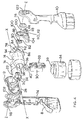
- Figure 8 shows a side cut-away view of the entry point of electrical wires into the drill head;
- Figure 9 shows a side cut-away view of the locking mechanism of the power tool;
- Figure 10 shows a detailed view of the locking mechanism shown in Figure 9;
- Figure 11 shows a side perspective view of the power tool with the rotatable drill head inclined at 135° to the handle;
- Figure 12 shows a side perspective view of the power tool with the rotatable
drill head
in line with the handle; and - Figure 13 shows a side perspective view of the power tool with the rotatable drill head perpendicular to the handle.
-
- Referring now to Figures 2 and 3, a power tool shown generally as (2) is a drill-driver comprising a substantially cylindrical drill head (4) having a longitudinal axis X and an elongate handle (6) arranged about a longitudinal axis Y. The drill head (4) is pivotally mounted upon the handle (6) and pivots relative to the handle (6) about an axis Z. The handle (6) is formed by a first clamshell (8) and a second clamshell (10) which are joined together by a plurality of screws (not shown). The drill head (4) is formed by a third clamshell (12) and a fourth clamshell (14) which are joined together by a plurality of screws (not shown).
- Referring to Figures 4 and 5, the drill head (4) comprises an electric motor (16) and a transmission gearbox (not shown) with an output spindle (20). The motor (16) and the gearbox are housed inside the drill head (4). The front end of the drill head (4) comprises a cylindrical gear casing (22) surrounding the gearbox and the output spindle (20). The motor (16) is rotatingly coupled to the gearbox such that rotary motion of the motor (16) is transferred to the output spindle (20) via the gearbox. The end portion of the output spindle (20) has a hex drive coupling (24) attached thereto. The output spindle (20) and the coupling (24) protrude through a hole (26) in the gear casing (22). The output spindle (20) and the coupling (24) rotate about the axis (x). The coupling (24) releasably connects the output spindle (20) to a tool (28) having a conventional hexagonal shank arrangement. Equally, another type of coupling like, for example, a conventional chuck can be attached to the end portion of the output spindle (20) for connection to a tool (28).
- The handle (8) comprises a button (30) fixed to a variable speed electrical switch (32). The switch (32) is electrically coupled to a power source (34). The switch (32) is also electrically coupled to the motor (16) by two electrical wires (36,38). The switch (32) is thermally coupled to a heat sink (39) located inside the handle (6). The heat sink (39) is for dissipating excess heat energy created by the internal components of the switch (32). The switch (32) is biased into an OFF position wherein the switch (32) interrupts electrical connection between the power source (38) and the motor (16) such that the motor (16) is denergised and the output spindle (20) does not rotate. Depression of the button (30) moves the switch (32) to an ON position wherein the switch (32) makes electrical connection between the power source (34) and the motor (16). The motor (20) is energised by the electrical current from the power source (34) and the output spindle (20) starts to rotate. Electrical current flowing from the power source (34) to the motor (16) is thus controlled by the switch (32) and is proportional to how far the button (30) is depressed. As depression of the button (30) increases so does flow of electrical current to the motor (16) causing a corresponding increase in the rotational speed of the output spindle (20), and vice versa. When the button (30) is released the switch (32) returns to the OFF position to interrupt the electrical connection between the power source (34) and the motor (16) thus causing denergision of the motor (16).
- Referring to Figures 6 and 7, the handle (6) comprises a direction selector (40) for selecting the rotational direction of the motor (16) and the output spindle (20). The direction selector (40) is approximately T-shaped and comprises a forward button (42) on one side, a reverse button (44) on the other side, and a flange (46) in the middle. To support the direction selector (40) the forward (42) and reverse (44) buttons partially protrude through an aperture in each of the first (8) and second (10) clamshells respectively. The handle also comprises a barrel (48) with an upper flange (50), a lower flange (52) and a central cylinder (54) located between the upper and lower flanges (52,54). The barrel's flanges (50,52) each have a mainly circular circumference part which is interrupted by a protruding part and are shaped like a tear-drop. The circular part of upper and lower flanges (50,52) has a diameter greater than the central cylinder (54). The protruding part of the upper flange (50) has an upper spigot (56). The protruding part of the lower flange (54) has a lower spigot (58). The upper and lower spigots (56,58) are eccentric with respect the axis of the central cylinder (54) and point axially away from the central cylinder (54). The barrel (48) is supported for pivotal rotation by a pair of brackets (60,62) which are moulded into interior of the handle's clamshells (8,10). The brackets (60,62) surround the central cylinder (54) to support the barrel (48) against lateral movement. The brackets (60,62) abut the inner faces of the upper and lower flanges (50,52) to support the barrel (48) against axial movement. The handle (6) further comprises an arm (64) with a hollow cylindrical hub (66) at one end and a finger (68) at the other end. The arm (64) is pivotally coupled to the internal components of the switch (32) at a point midway between the hub (66) and the finger (68). The arm (64) can pivot between a forward position, a central position and a reverse position. Pivotal movement of the arm (64) from its forward position to its reverse position, and vice versa, causes the switch (32) to change the polarity of the electrical wires (36,38), as explained in more detail below.
- The direction selector (40) is mechanically coupled to the switch (32) via the barrel (48) and the arm (64) in the following manner. The barrel's upper spigot (56) engages the direction selector (40) by protruding through a hole in the flange (46). The barrel's lower spigot (58) is seated within the arm's hollow cylindrical hub (66) in the manner of a trunnion arrangement. As such, depression of the forward button (42) slides the direction selector (40) and the upper spigot (56) in one direction thereby rotating the barrel (48) about its axis. Rotation of the barrel (48) moves the lower spigot (58) in the opposite direction thereby pivoting the arm (64) into its forward position. Depression of the reverse button (44) reverses this sequence and causes the arm (64) to pivot from its forward position to its reverse position.
- When the arm (64) is in its forward position the polarity of the wires (36,38) causes the motor (16) to turn the output spindle (20) in a clockwise direction when the switch (32) is in the ON position. When the arm (64) in its reverse position the polarity of the wires (36,38) is reversed and the motor (16) to turns the output spindle (20) in an anti-clockwise direction when the switch (32) is in the ON position. When the arm (64) is in its central position the arm's finger (68) is aligned with and abuts a central stop (70) on the interior of the button (30) thereby preventing depression of the button (30) and locking the switch (32) in the OFF position.
- The direction selector's buttons (42,44) are arrow-head shaped. The apex of the forward button (42) points forward to give the user a visual and tangible indication that depression of the forward button (42) causes the output spindle (20) to rotate in a clockwise direction (i.e. the rotational direction causing a screw or drill bit to be driven "forward" into a work piece) when the switch (32) is in the ON position. Conversely, the apex of the reverse button (44) points backward to give the user a visual and tangible indication that depression of the reverse button (42) causes the output spindle (20) to rotate in an anti-clockwise direction when the switch (32) is in the ON position.
- The power source is a rechargeable battery pack (34) housed inside the bottom of the handle (6). To improve the electrical charge of the battery pack (34), thereby increasing operating life, the battery pack (34) is relatively bulky causing the handle (6) to protrude on the side of the switch button (30). The battery pack (34) is electrically coupled to a battery recharger socket (72) located at the lower end of the handle (6). The battery recharger socket (72) protrudes through a small aperture (74) in the handle (6) to provide an electrical link between the battery pack (34) and an external battery recharging source (not shown). Alternatively, the power source may be a rechargeable battery detachably fixed to the handle (6), or a mains electrical supply.
- Returning to Figures 4 and 5, the drill head (4) has a first cylindrical hub (76) and a second cylindrical hub (78) both located part way along the length of the drill head (4), remote from the output spindle (20). The first and second hubs (76,78) are located on opposite sides of the drill head (4). The first and second hubs (76, 78) are substantially the same diameter and both arranged about axis Z. The first and second hubs (76, 78) extend from the drill head (4) in diametrically opposed directions along axis Z. Axis Z is perpendicular to axis's X and Y.
- Referring to Figure 8, the first cylindrical hub (76) is moulded into the third clam shell (12) of the drill head (4). The first cylindrical hub (76) comprises a central inner aperture (80) co-axial with axis Z. The inner aperture (80) provides an entry point to the interior of the drill head (4). Referring to Figures 9 and 10, the second hub (78) comprises a circular toothed wheel (82), a protrusion (86) and, a cylindrical spigot (84) having axis Z. The protrusion (86) and the spigot (84) are moulded into the fourth clam shell (14) of the drill head (4). The wheel (82) comprises a central aperture (88) and a plurality of teeth (90) arranged equi-angularly around the circumference of the wheel (82). The toothed wheel (82) has eight teeth'(90) juxtaposed by eight recesses (92) for engagement with part of a locking plate, which is described in more detail below. The eight teeth (90) are arranged at 45° intervals about the axis Z. The wheel (82) is press fitted upon the fourth clam shell (14). Two of the eight teeth (90) are shorter than the outer diameter of the wheel (82). The protrusion (86) has a curved exterior face (94) and an interior face (96) shaped to surround the two short teeth (90) and engage three recesses (92a, 92b, 92c) adjacent the two short teeth (90) thereby preventing rotation of the wheel (82) relative to the drill head (4). The spigot (84) protrudes through the aperture (88). The outer diameter of the spigot (84) is slightly larger that the diameter of the aperture (88) such that interference fit between the spigot (84) and the circumference of the aperture (88) holds the wheel (82) upon the drill head (4). The curved exterior face (94) of the protrusion (86) and the tips of the teeth (90) collectively describe the outer circumference of the second hub (78). The wheel (82) is made of steel, Alternatively, the wheel (82) may be made of another suitable hard material.
- Returning again to Figures 4 and 5, located at the top end of the handle (6) (opposite end to the battery pack) is a first supporting bracket (98) and a second supporting bracket (100) each shaped to nest in the interior of the first and the second clamshells (8,10) of the handle (6), respectively. The first bracket (98) has a circular aperture (102) for receiving the first hub (76). The second bracket (100) has a circular aperture (104) for receiving the second hub (76). The first and second hubs (76,78), the first and second bracket apertures (102,104), the first hub aperture (80) and the spigot (84) are co-axial having axis Z. The first and second bracket apertures (102,104) act as a yoke in which the first and second hubs (76,78) are supported for pivotal rotation relative to the handle (6). As such, the first and second bracket apertures (102,104) provide pivotal support to the first and second hubs (76,78), respectively, to allow the drill head (4) to pivot relative the handle (6) about axis Z.
- Returning to Figure 8, the first support bracket (98) has a first walled recess (106) facing the interior of the first clam shell (8) of the handle (6). A cavity (108) bounded by the walled recess (106) and the interior of the first clam shell (8) is formed therebetween. The cavity (108) provides a connecting passageway from the interior of the handle (6) to first hub (76) for the wires (36,38). Accordingly, the wires (36,38) travel from the switch (32) via the cavity (108) through the first hub's aperture (80) to the motor (20) inside the drill head (4).
- Returning to Figures 9 and 10, The second support bracket (100) has a second walled recess (110) facing the interior of the first clam shell (10) of the handle (6). A space (112) bounded by the second walled recess (110) and the interior of the second clam shell (10) is formed therebetween. The space (112) contains a locking plate (114), a lock release button (116) fixed to the locking plate (114), and two helical springs (118). The locking plate (114) has a tongue (120) which is for locking engagement with any one of the five recesses (92d to 92h) of the toothed wheel (82) not occupied by the interior face (96) of the protrusion (86).
- The locking plate (114), the lock release button (116), and the two helical springs (118) collectively form a locking mechanism for locking pivotal movement of the head (4) relative to the handle (6) about the axis Z. The tongue (120) of the locking plate (114) is biased into engagement with a recess (92) by the springs (118), thereby locking pivotal movement of the head (4) relative to the handle (6). To allow pivotal movement of the head (4) relative to the handle (6) the user disengages the tongue (120) from a recess (92) by sliding the locking plate (114) and the release button (116) against the bias of the springs (118). Sliding movement of the locking plate (114) is guided by the second walled recess (110). Access to the release button (116) for operation of the locking plate (114) is provided by a hole (122) in the top end of the second clamshell (10) of the handle (6).
- Referring now to Figures 10 to 13, axis Z is the axis about which the head (4) pivots with respect to the handle (6). Axis Y represents the position of the handle (6) and axis X represents the position of the drill head (4). Both axis X and Y remain perpendicular to axis Z regardless of the orientation of the drill head (4) in relation to the handle (8). The included angle between axis X and Y is referred to as angle α. Only angle α varies when the drill head (4) changes its orientation in relation to the handle (8) by pivoting about the axis Z. Angle α is dictated by which one of the five unoccupied recesses (92d to 92h) engages the tongue (120) of the locking plate (114). Angle α is 90° when recess (92d) engages the tongue (120), as shown in Figure 13. Recess (92e) is located 45° anti-clockwise from recess (92d), therefore angle α is 135° when recess (92e) engages the tongue (120), as shown in Figure11. Angle α is 180°, 225° and 270° when one of the three respective subsequent recesses (92f, 92g, 92h) engage the tongue (120).
- In the illustrated embodiment of the present invention, angle α can be set to five positions within a range of 180°, according to which one of the five unoccupied recesses (92d to 92h) engages the locking plate (114). However the range of angle α can be increased from 180° by reducing the number of recesses (92) engaged by the interior face (96) of the protrusion (86) from three recesses (92a, 92b, 92c) to two recesses, or even only one recess. Also, the number of positions within the range of angle α can be varied by changing the number of recesses (92) and teeth (90), or varying the angular spacing between adjacent recesses (92) and teeth (90) around the circumference of the toothed wheel (82).
Claims (20)
- A power tool (2) comprising:characterised in that an electrical connection (36,38) between the handle (6) and the tool body (4) passes through the pivot (76,78,102,104).a handle (6); anda tool body (4) pivotally coupled to the handle (6) by a pivot (76,78,102,104)
- A power tool (2) as claimed in claim 1, wherein the pivot (76,78,102,104) has a first axis (z) and a connection aperture (80) substantially concentric with the first axis (z), wherein the electrical connection (36,38) passes though the connection aperture (80).
- A power tool (2) as claimed in either one of claims 1 or 2, wherein the electrical connection comprises two electrical wires (36,38).
- A power tool (2) as claimed in claim 3 when appended to claim 2, wherein a gap between the two electrical wires (36,38) and the connection aperture (80) is sealed.
- A power tool (2) as claimed in claim 2 or either one of claims 3 or 4 when appended to claim 2, wherein the pivot (76,78,102,104) comprises:wherein the at least one aperture (102,104) has the first axis (z), and wherein the at least one cylindrical hub (76,78) is disposed concentrically within a respective aperture (102,104) such that sliding contact between the at least one hub (76,78) and a respective aperture (102,104) supports the tool head (4) for pivotal rotation relative to the handle (6).at least one circular aperture (102,104) formed in one of the tool body (4) or the handle (6); andat least one cylindrical hub (76,78) protruding from the other of the tool body (4) or the handle (6),
- A power tool (2) as claimed in claim 5, wherein the at least one aperture (102,104) is formed in the handle (6) and the at least one hub (76,78) is disposed upon the tool body (4).
- A power tool (2) as claimed in either one of claims 5 or 6, wherein the at least one aperture (102,104) comprises a first aperture (102) and a second aperture (104), the first aperture (102) and the second aperture (104) each having the first axis (z), and wherein the at least one hub (76,78) comprises a first hub (76) disposed concentrically within the first aperture (102) and a second hub (78) disposed concentrically within the second aperture (104).
- A power tool (2) in claimed in claim 7, wherein the connection aperture (80) is in the first hub (76).
- A power tool (2) claimed in claim 2 or any one of claims 3 to 8 when appended to claim 2, wherein the tool body (4) is elongate and has a second axis (x) perpendicular to the first axis (z) and the power tool (2) comprises a motor (16) coupled to a rotary output (20), wherein the rotary output (20) has the second axis (x).
- A power tool (2) as claimed in claim 9, wherein the motor (16) is housed in the tool body (4).
- A power tool (2) as claimed in claim 10, wherein the power tool (2) further comprises:wherein the switch (32) is disposed upon the handle (6) and the electrical connection (36,38) carries electrical current from the switch (32) to the motor (16) housed in the tool body (4).a power source (34) for energising the motor (16); andan electrical switch (32) electrically coupled to the power source (34);
- A power tool (2) as claimed in claim 11, wherein the power source is a battery pack (34).
- A power tool (2) as claimed in claim 12, wherein the battery pack (34) is housed within the handle (6).
- A power tool (2) as claimed in either one of claims 12 or 13, wherein the battery pack (34) is electrically coupled to an electrical socket (72) disposed upon the handle (6), which electrical socket (72) is for connection to an external battery charging source.
- A power tool (2) as claimed in claim 12, wherein the battery pack (34) is detachably connected to the handle (6).
- A power tool (2) claimed in claim 2 or any one of claims 3 to 15 when appended to claim 2, wherein the handle (6) is elongate and has a third axis (y), which third axis (y) is perpendicular to the first axis (z).
- A power tool (2) as claimed in claim 16 when appended to any one of claims 9 to 15, wherein an arc defined by pivotal rotation of the tool head (4) relative to the handle (6) about the first axis (z) subtends a pivotal angle (α) between the second axis (x) and the third axis (y), which pivotal angle (α) can vary by more than 90°.
- A power tool (2) as claimed in claim 17, wherein the pivotal angle (α) can vary by 180°
- A power tool (2) as claimed in either one of claims 17 or 18, wherein the value of the pivotal angle (α) can vary between 90° and 270°.
- A power tool (2) as claimed in any one of the previous claims, wherein the power tool (2) further comprises a locking mechanism for locking the tool body (4) against pivotal movement relative to the handle (6).
Applications Claiming Priority (2)
| Application Number | Priority Date | Filing Date | Title |
|---|---|---|---|
| GB0127825 | 2001-11-20 | ||
| GB0127825A GB2382048A (en) | 2001-11-20 | 2001-11-20 | Pivoting electrical connection for a power tool |
Publications (3)
| Publication Number | Publication Date |
|---|---|
| EP1313180A2 true EP1313180A2 (en) | 2003-05-21 |
| EP1313180A3 EP1313180A3 (en) | 2004-01-07 |
| EP1313180B1 EP1313180B1 (en) | 2012-05-02 |
Family
ID=9926128
Family Applications (1)
| Application Number | Title | Priority Date | Filing Date |
|---|---|---|---|
| EP02024799A Expired - Lifetime EP1313180B1 (en) | 2001-11-20 | 2002-11-07 | An electrical connection for a power drill or power screwdriver |
Country Status (6)
| Country | Link |
|---|---|
| US (1) | US7281591B2 (en) |
| EP (1) | EP1313180B1 (en) |
| CN (1) | CN1281382C (en) |
| AT (1) | ATE556471T1 (en) |
| AU (1) | AU2002302086B2 (en) |
| GB (1) | GB2382048A (en) |
Cited By (5)
| Publication number | Priority date | Publication date | Assignee | Title |
|---|---|---|---|---|
| GB2402360B (en) * | 2003-06-03 | 2007-04-04 | Milwaukee Electric Tool Corp | Handle arrangement for a reciprocating saw |
| WO2007112182A1 (en) * | 2006-03-24 | 2007-10-04 | Draeger Safety, Inc. | Crawling handle for thermal imaging camera |
| EP1894677A2 (en) | 2006-08-31 | 2008-03-05 | Matsushita Electric Works, Ltd. | Cordless power tool |
| EP3055603B1 (en) | 2013-10-11 | 2020-09-16 | Designerscope Limited | Cabinet levelling apparatus |
| US11786035B2 (en) | 2017-09-04 | 2023-10-17 | Designerscope Limited | Cabinet levelling apparatus |
Families Citing this family (28)
| Publication number | Priority date | Publication date | Assignee | Title |
|---|---|---|---|---|
| JP2006321043A (en) | 2005-05-17 | 2006-11-30 | Milwaukee Electric Tool Corp | Power tool, battery, battery charger, and operating method thereof |
| DE102006023187B4 (en) | 2005-05-17 | 2020-02-27 | Milwaukee Electric Tool Corp. | Method for operating a battery charger and a combination comprising a battery and a battery charger |
| EP1943060B1 (en) * | 2005-11-04 | 2019-08-14 | Robert Bosch Gmbh | Articulating drill with integrated circuit board and method of operation |
| US8061043B2 (en) | 2006-11-15 | 2011-11-22 | Milwaukee Electric Tool Corporation | Power tool |
| JP2009083089A (en) * | 2007-09-14 | 2009-04-23 | Makita Corp | Handle part of hand type electric tool |
| US7762349B2 (en) | 2007-11-21 | 2010-07-27 | Black & Decker Inc. | Multi-speed drill and transmission with low gear only clutch |
| US7717191B2 (en) | 2007-11-21 | 2010-05-18 | Black & Decker Inc. | Multi-mode hammer drill with shift lock |
| US7798245B2 (en) | 2007-11-21 | 2010-09-21 | Black & Decker Inc. | Multi-mode drill with an electronic switching arrangement |
| US7717192B2 (en) | 2007-11-21 | 2010-05-18 | Black & Decker Inc. | Multi-mode drill with mode collar |
| US7735575B2 (en) | 2007-11-21 | 2010-06-15 | Black & Decker Inc. | Hammer drill with hard hammer support structure |
| US7770660B2 (en) * | 2007-11-21 | 2010-08-10 | Black & Decker Inc. | Mid-handle drill construction and assembly process |
| US7854274B2 (en) | 2007-11-21 | 2010-12-21 | Black & Decker Inc. | Multi-mode drill and transmission sub-assembly including a gear case cover supporting biasing |
| FR2929544B1 (en) * | 2008-04-02 | 2010-09-03 | Facom | AUTONOMOUS PORTABLE ELECTRICAL APPARATUS WITH ELECTRIC POWER SUPPLY BLOCK LOCKING. |
| US20100178856A1 (en) * | 2009-01-09 | 2010-07-15 | Omar Jesus Cruz | Cordless power gasket scraper and surface cleaning tool with light source |
| WO2011075675A2 (en) | 2009-12-18 | 2011-06-23 | Milwaukee Electric Tool Corporation | Multi motion switch with multiplier arm |
| DE102009054967A1 (en) * | 2009-12-18 | 2011-06-22 | Robert Bosch GmbH, 70469 | Machine tool with electric drive motor |
| CN101926670B (en) * | 2010-09-30 | 2013-05-08 | 重庆润泽医疗器械有限公司 | Craniotomy drill |
| US20120325511A1 (en) * | 2011-06-21 | 2012-12-27 | Ming-Ta Cheng | Air-inlet switching assembly for a pneumatic tool |
| EP2799188A4 (en) * | 2011-12-28 | 2015-08-12 | Positec Power Tools Suzhou Co | Power tool |
| US10821591B2 (en) | 2012-11-13 | 2020-11-03 | Milwaukee Electric Tool Corporation | High-power cordless, hand-held power tool including a brushless direct current motor |
| US9956676B2 (en) * | 2013-01-09 | 2018-05-01 | Techtronic Power Tools Technology Limited | Tool with rotatable head |
| US10030423B2 (en) * | 2015-12-30 | 2018-07-24 | Robert Bosch Gmbh | Movable joint |
| CN105666429B (en) * | 2016-02-02 | 2019-05-28 | 宁波市国冠自动化技术有限公司 | A kind of rotary power tool |
| US11431224B2 (en) * | 2017-02-15 | 2022-08-30 | Black & Decker Inc. | Power and home tools |
| DE102017210467A1 (en) * | 2017-06-22 | 2018-12-27 | Robert Bosch Gmbh | Hand tool |
| EP3483680A3 (en) * | 2017-09-15 | 2019-06-19 | Defond Electech Co., Ltd | A control assembly for an electric device |
| EP3838780B1 (en) * | 2019-12-06 | 2024-05-01 | Ei Beheer B.V. | Dispenser for stretch film |
| CN113696145B (en) * | 2020-05-21 | 2023-12-19 | 南京泉峰科技有限公司 | Electric tool |
Citations (4)
| Publication number | Priority date | Publication date | Assignee | Title |
|---|---|---|---|---|
| DE8505814U1 (en) * | 1985-03-01 | 1985-05-30 | Proxxon GmbH, 5561 Niersbach | ELECTRIC TOOL |
| US5681214A (en) * | 1995-12-12 | 1997-10-28 | Robert Bosch Gmbh | Hand power tool |
| EP0993909A2 (en) * | 1998-10-16 | 2000-04-19 | Black & Decker Inc. | Two-position screwdriver housing |
| EP1059025A2 (en) * | 1999-06-10 | 2000-12-13 | GARDENA Kress + Kastner GmbH | Motor-driven garden tool, particularly hedge trimmer |
Family Cites Families (19)
| Publication number | Priority date | Publication date | Assignee | Title |
|---|---|---|---|---|
| DE2514940C2 (en) | 1975-04-05 | 1985-03-07 | Wilhelm Bahmüller Maschinen- und Apparatebau, 7067 Plüderhausen | Joint that can be locked in several working positions to connect the ladder stiles to a ladder that can be locked in several positions or the like. |
| US4347450A (en) * | 1980-12-10 | 1982-08-31 | Colligan Wallace M | Portable power tool |
| JPS5914476A (en) * | 1982-07-16 | 1984-01-25 | 松下電工株式会社 | Electric driver |
| DE3542637A1 (en) | 1985-12-03 | 1987-06-04 | Gimelli & Co Ag | Hand-held household appliance |
| US4645371A (en) | 1986-05-01 | 1987-02-24 | Wang Chien Yuan | Safety joint mechanism, particularly for folding ladders |
| US4912349A (en) | 1989-05-16 | 1990-03-27 | Chang Jung C | Pivotally adjustable electric hand tool |
| US5022118A (en) | 1990-06-25 | 1991-06-11 | Wan Dean Industry Co. | Ladder joint with engagement spring member |
| US5149230A (en) | 1991-03-04 | 1992-09-22 | Nett Daniel R | Rotating dual attachment receptacle apparatus tool |
| US5161293A (en) | 1991-04-15 | 1992-11-10 | Ebbert Engineering, Inc. | Adjustable handle for hand tool |
| DE9309682U1 (en) | 1993-06-24 | 1993-08-26 | Huang, Chen-Shu-Hsia, Hsinchuang, Taipeh | Screwdriver |
| DE19629902A1 (en) | 1996-07-24 | 1998-01-29 | Kaltenbach & Voigt | Angular or straight handpiece with a releasable clamping device for a rotating tool, in particular for medical or dental purposes |
| US5816614A (en) | 1997-03-21 | 1998-10-06 | Burke, Inc. | Tiller assembly for personal mobility vehicles |
| US6039126A (en) | 1998-05-15 | 2000-03-21 | Hsieh; An-Fu | Multi-usage electric tool with angle-changeable grip |
| USD443491S1 (en) | 2000-08-15 | 2001-06-12 | Black & Decker Inc. | Multiposition screwdriver |
| USD447924S1 (en) | 2000-11-02 | 2001-09-18 | Milwaukee Electric Tool Corporation | Handle arrangement for a reciprocating saw |
| US6364033B1 (en) * | 2001-08-27 | 2002-04-02 | Techtronic Industries Co. Ltd. | Portable electric tool |
| GB2382044A (en) * | 2001-11-20 | 2003-05-21 | Black & Decker Inc | A power tool having a handle and a pivotal tool body |
| USD476542S1 (en) * | 2001-12-05 | 2003-07-01 | One World Technologies Limited | Pivot driver |
| ATE392998T1 (en) * | 2002-06-07 | 2008-05-15 | Black & Decker Inc | POWER-DRIVEN TOOL WITH LOCKING DEVICE |
-
2001
- 2001-11-20 GB GB0127825A patent/GB2382048A/en not_active Withdrawn
-
2002
- 2002-11-07 AT AT02024799T patent/ATE556471T1/en active
- 2002-11-07 US US10/289,877 patent/US7281591B2/en not_active Expired - Fee Related
- 2002-11-07 EP EP02024799A patent/EP1313180B1/en not_active Expired - Lifetime
- 2002-11-18 AU AU2002302086A patent/AU2002302086B2/en not_active Ceased
- 2002-11-19 CN CN02160632.3A patent/CN1281382C/en not_active Expired - Fee Related
Patent Citations (4)
| Publication number | Priority date | Publication date | Assignee | Title |
|---|---|---|---|---|
| DE8505814U1 (en) * | 1985-03-01 | 1985-05-30 | Proxxon GmbH, 5561 Niersbach | ELECTRIC TOOL |
| US5681214A (en) * | 1995-12-12 | 1997-10-28 | Robert Bosch Gmbh | Hand power tool |
| EP0993909A2 (en) * | 1998-10-16 | 2000-04-19 | Black & Decker Inc. | Two-position screwdriver housing |
| EP1059025A2 (en) * | 1999-06-10 | 2000-12-13 | GARDENA Kress + Kastner GmbH | Motor-driven garden tool, particularly hedge trimmer |
Cited By (10)
| Publication number | Priority date | Publication date | Assignee | Title |
|---|---|---|---|---|
| GB2402360B (en) * | 2003-06-03 | 2007-04-04 | Milwaukee Electric Tool Corp | Handle arrangement for a reciprocating saw |
| WO2007112182A1 (en) * | 2006-03-24 | 2007-10-04 | Draeger Safety, Inc. | Crawling handle for thermal imaging camera |
| GB2450300A (en) * | 2006-03-24 | 2008-12-17 | Draeger Safety Inc | Crawling handle for thermal imaging camera |
| GB2450300B (en) * | 2006-03-24 | 2010-06-23 | Draeger Safety Inc | Crawling handle for thermal imaging camera |
| EP1894677A2 (en) | 2006-08-31 | 2008-03-05 | Matsushita Electric Works, Ltd. | Cordless power tool |
| EP1894677A3 (en) * | 2006-08-31 | 2010-08-04 | Panasonic Electric Works Co., Ltd. | Cordless power tool |
| EP3055603B1 (en) | 2013-10-11 | 2020-09-16 | Designerscope Limited | Cabinet levelling apparatus |
| EP3767151A1 (en) | 2013-10-11 | 2021-01-20 | Designerscope Limited | Cabinet levelling apparatus |
| EP3767151B1 (en) | 2013-10-11 | 2024-07-03 | Häfele SE & Co KG | Cabinet levelling apparatus |
| US11786035B2 (en) | 2017-09-04 | 2023-10-17 | Designerscope Limited | Cabinet levelling apparatus |
Also Published As
| Publication number | Publication date |
|---|---|
| US20060086517A1 (en) | 2006-04-27 |
| EP1313180A3 (en) | 2004-01-07 |
| EP1313180B1 (en) | 2012-05-02 |
| ATE556471T1 (en) | 2012-05-15 |
| AU2002302086B2 (en) | 2007-07-26 |
| CN1421301A (en) | 2003-06-04 |
| GB2382048A (en) | 2003-05-21 |
| US7281591B2 (en) | 2007-10-16 |
| GB0127825D0 (en) | 2002-01-09 |
| CN1281382C (en) | 2006-10-25 |
Similar Documents
| Publication | Publication Date | Title |
|---|---|---|
| EP1313180B1 (en) | An electrical connection for a power drill or power screwdriver | |
| US7055622B2 (en) | Power tool having a handle and a pivotal tool body | |
| EP1313116B1 (en) | Switch mechanism for an electric power tool | |
| US6938706B2 (en) | Power tool provided with a locking mechanism | |
| US7814816B2 (en) | Power tool, battery, charger and method of operating the same | |
| US6296427B1 (en) | Two speed right angle drill | |
| CA2838958C (en) | Tool with rotatable head | |
| US8602582B2 (en) | Articulating tool with illumination | |
| US5089738A (en) | Battery-driven handtool | |
| EP0118215B1 (en) | Hand-held power tool with shaft lock | |
| JPH03202283A (en) | Power tool | |
| GB2324492A (en) | Wrench with rotatable handgrip | |
| GB2429420A (en) | Handheld power tool | |
| CN214815368U (en) | Multifunctional reciprocating cutting tool | |
| JPH07266114A (en) | Dual purpose drill | |
| KR19980026566A (en) | Transmission of cordless power tools |
Legal Events
| Date | Code | Title | Description |
|---|---|---|---|
| PUAI | Public reference made under article 153(3) epc to a published international application that has entered the european phase |
Free format text: ORIGINAL CODE: 0009012 |
|
| AK | Designated contracting states |
Designated state(s): AT BE BG CH CY CZ DE DK EE ES FI FR GB GR IE IT LI LU MC NL PT SE SK TR |
|
| AX | Request for extension of the european patent |
Extension state: AL LT LV MK RO SI |
|
| PUAL | Search report despatched |
Free format text: ORIGINAL CODE: 0009013 |
|
| AK | Designated contracting states |
Kind code of ref document: A3 Designated state(s): AT BE BG CH CY CZ DE DK EE ES FI FR GB GR IE IT LI LU MC NL PT SE SK TR |
|
| AX | Request for extension of the european patent |
Extension state: AL LT LV MK RO SI |
|
| 17P | Request for examination filed |
Effective date: 20040202 |
|
| 17Q | First examination report despatched |
Effective date: 20040330 |
|
| AKX | Designation fees paid |
Designated state(s): AT BE BG CH CY CZ DE DK EE ES FI FR GB GR IE IT LI LU MC NL PT SE SK TR |
|
| 17Q | First examination report despatched |
Effective date: 20040330 |
|
| RTI1 | Title (correction) |
Free format text: AN ELECTRICAL CONNECTION FOR A POWER DRILL OR POWER SCREWDRIVER |
|
| GRAP | Despatch of communication of intention to grant a patent |
Free format text: ORIGINAL CODE: EPIDOSNIGR1 |
|
| GRAS | Grant fee paid |
Free format text: ORIGINAL CODE: EPIDOSNIGR3 |
|
| GRAA | (expected) grant |
Free format text: ORIGINAL CODE: 0009210 |
|
| AK | Designated contracting states |
Kind code of ref document: B1 Designated state(s): AT BE BG CH CY CZ DE DK EE ES FI FR GB GR IE IT LI LU MC NL PT SE SK TR |
|
| REG | Reference to a national code |
Ref country code: GB Ref legal event code: FG4D |
|
| REG | Reference to a national code |
Ref country code: AT Ref legal event code: REF Ref document number: 556471 Country of ref document: AT Kind code of ref document: T Effective date: 20120515 Ref country code: CH Ref legal event code: EP |
|
| REG | Reference to a national code |
Ref country code: IE Ref legal event code: FG4D |
|
| REG | Reference to a national code |
Ref country code: DE Ref legal event code: R096 Ref document number: 60242787 Country of ref document: DE Effective date: 20120705 |
|
| REG | Reference to a national code |
Ref country code: NL Ref legal event code: VDEP Effective date: 20120502 |
|
| PG25 | Lapsed in a contracting state [announced via postgrant information from national office to epo] |
Ref country code: SE Free format text: LAPSE BECAUSE OF FAILURE TO SUBMIT A TRANSLATION OF THE DESCRIPTION OR TO PAY THE FEE WITHIN THE PRESCRIBED TIME-LIMIT Effective date: 20120502 Ref country code: FI Free format text: LAPSE BECAUSE OF FAILURE TO SUBMIT A TRANSLATION OF THE DESCRIPTION OR TO PAY THE FEE WITHIN THE PRESCRIBED TIME-LIMIT Effective date: 20120502 Ref country code: CY Free format text: LAPSE BECAUSE OF FAILURE TO SUBMIT A TRANSLATION OF THE DESCRIPTION OR TO PAY THE FEE WITHIN THE PRESCRIBED TIME-LIMIT Effective date: 20120502 |
|
| REG | Reference to a national code |
Ref country code: AT Ref legal event code: MK05 Ref document number: 556471 Country of ref document: AT Kind code of ref document: T Effective date: 20120502 |
|
| PG25 | Lapsed in a contracting state [announced via postgrant information from national office to epo] |
Ref country code: GR Free format text: LAPSE BECAUSE OF FAILURE TO SUBMIT A TRANSLATION OF THE DESCRIPTION OR TO PAY THE FEE WITHIN THE PRESCRIBED TIME-LIMIT Effective date: 20120803 Ref country code: PT Free format text: LAPSE BECAUSE OF FAILURE TO SUBMIT A TRANSLATION OF THE DESCRIPTION OR TO PAY THE FEE WITHIN THE PRESCRIBED TIME-LIMIT Effective date: 20120903 |
|
| PG25 | Lapsed in a contracting state [announced via postgrant information from national office to epo] |
Ref country code: BE Free format text: LAPSE BECAUSE OF FAILURE TO SUBMIT A TRANSLATION OF THE DESCRIPTION OR TO PAY THE FEE WITHIN THE PRESCRIBED TIME-LIMIT Effective date: 20120502 |
|
| PG25 | Lapsed in a contracting state [announced via postgrant information from national office to epo] |
Ref country code: AT Free format text: LAPSE BECAUSE OF FAILURE TO SUBMIT A TRANSLATION OF THE DESCRIPTION OR TO PAY THE FEE WITHIN THE PRESCRIBED TIME-LIMIT Effective date: 20120502 Ref country code: NL Free format text: LAPSE BECAUSE OF FAILURE TO SUBMIT A TRANSLATION OF THE DESCRIPTION OR TO PAY THE FEE WITHIN THE PRESCRIBED TIME-LIMIT Effective date: 20120502 Ref country code: EE Free format text: LAPSE BECAUSE OF FAILURE TO SUBMIT A TRANSLATION OF THE DESCRIPTION OR TO PAY THE FEE WITHIN THE PRESCRIBED TIME-LIMIT Effective date: 20120502 Ref country code: CZ Free format text: LAPSE BECAUSE OF FAILURE TO SUBMIT A TRANSLATION OF THE DESCRIPTION OR TO PAY THE FEE WITHIN THE PRESCRIBED TIME-LIMIT Effective date: 20120502 Ref country code: SK Free format text: LAPSE BECAUSE OF FAILURE TO SUBMIT A TRANSLATION OF THE DESCRIPTION OR TO PAY THE FEE WITHIN THE PRESCRIBED TIME-LIMIT Effective date: 20120502 Ref country code: DK Free format text: LAPSE BECAUSE OF FAILURE TO SUBMIT A TRANSLATION OF THE DESCRIPTION OR TO PAY THE FEE WITHIN THE PRESCRIBED TIME-LIMIT Effective date: 20120502 |
|
| PG25 | Lapsed in a contracting state [announced via postgrant information from national office to epo] |
Ref country code: IT Free format text: LAPSE BECAUSE OF FAILURE TO SUBMIT A TRANSLATION OF THE DESCRIPTION OR TO PAY THE FEE WITHIN THE PRESCRIBED TIME-LIMIT Effective date: 20120502 |
|
| PLBE | No opposition filed within time limit |
Free format text: ORIGINAL CODE: 0009261 |
|
| STAA | Information on the status of an ep patent application or granted ep patent |
Free format text: STATUS: NO OPPOSITION FILED WITHIN TIME LIMIT |
|
| 26N | No opposition filed |
Effective date: 20130205 |
|
| PG25 | Lapsed in a contracting state [announced via postgrant information from national office to epo] |
Ref country code: ES Free format text: LAPSE BECAUSE OF FAILURE TO SUBMIT A TRANSLATION OF THE DESCRIPTION OR TO PAY THE FEE WITHIN THE PRESCRIBED TIME-LIMIT Effective date: 20120813 |
|
| REG | Reference to a national code |
Ref country code: DE Ref legal event code: R097 Ref document number: 60242787 Country of ref document: DE Effective date: 20130205 |
|
| REG | Reference to a national code |
Ref country code: CH Ref legal event code: PL |
|
| PG25 | Lapsed in a contracting state [announced via postgrant information from national office to epo] |
Ref country code: BG Free format text: LAPSE BECAUSE OF FAILURE TO SUBMIT A TRANSLATION OF THE DESCRIPTION OR TO PAY THE FEE WITHIN THE PRESCRIBED TIME-LIMIT Effective date: 20120802 Ref country code: CH Free format text: LAPSE BECAUSE OF NON-PAYMENT OF DUE FEES Effective date: 20121130 Ref country code: LI Free format text: LAPSE BECAUSE OF NON-PAYMENT OF DUE FEES Effective date: 20121130 |
|
| REG | Reference to a national code |
Ref country code: IE Ref legal event code: MM4A |
|
| REG | Reference to a national code |
Ref country code: FR Ref legal event code: ST Effective date: 20130731 |
|
| PG25 | Lapsed in a contracting state [announced via postgrant information from national office to epo] |
Ref country code: IE Free format text: LAPSE BECAUSE OF NON-PAYMENT OF DUE FEES Effective date: 20121107 |
|
| PG25 | Lapsed in a contracting state [announced via postgrant information from national office to epo] |
Ref country code: FR Free format text: LAPSE BECAUSE OF NON-PAYMENT OF DUE FEES Effective date: 20121130 |
|
| PG25 | Lapsed in a contracting state [announced via postgrant information from national office to epo] |
Ref country code: TR Free format text: LAPSE BECAUSE OF FAILURE TO SUBMIT A TRANSLATION OF THE DESCRIPTION OR TO PAY THE FEE WITHIN THE PRESCRIBED TIME-LIMIT Effective date: 20120502 Ref country code: MC Free format text: LAPSE BECAUSE OF NON-PAYMENT OF DUE FEES Effective date: 20121130 |
|
| PG25 | Lapsed in a contracting state [announced via postgrant information from national office to epo] |
Ref country code: LU Free format text: LAPSE BECAUSE OF NON-PAYMENT OF DUE FEES Effective date: 20121107 |
|
| PGFP | Annual fee paid to national office [announced via postgrant information from national office to epo] |
Ref country code: GB Payment date: 20151104 Year of fee payment: 14 Ref country code: DE Payment date: 20151103 Year of fee payment: 14 |
|
| REG | Reference to a national code |
Ref country code: DE Ref legal event code: R119 Ref document number: 60242787 Country of ref document: DE |
|
| GBPC | Gb: european patent ceased through non-payment of renewal fee |
Effective date: 20161107 |
|
| PG25 | Lapsed in a contracting state [announced via postgrant information from national office to epo] |
Ref country code: GB Free format text: LAPSE BECAUSE OF NON-PAYMENT OF DUE FEES Effective date: 20161107 Ref country code: DE Free format text: LAPSE BECAUSE OF NON-PAYMENT OF DUE FEES Effective date: 20170601 |