EP1312932A1 - Method for measuring motor constant of induction motor - Google Patents
Method for measuring motor constant of induction motor Download PDFInfo
- Publication number
- EP1312932A1 EP1312932A1 EP01947850A EP01947850A EP1312932A1 EP 1312932 A1 EP1312932 A1 EP 1312932A1 EP 01947850 A EP01947850 A EP 01947850A EP 01947850 A EP01947850 A EP 01947850A EP 1312932 A1 EP1312932 A1 EP 1312932A1
- Authority
- EP
- European Patent Office
- Prior art keywords
- current
- value
- ref
- motor
- axis
- Prior art date
- Legal status (The legal status is an assumption and is not a legal conclusion. Google has not performed a legal analysis and makes no representation as to the accuracy of the status listed.)
- Granted
Links
Images



Classifications
-
- G—PHYSICS
- G01—MEASURING; TESTING
- G01R—MEASURING ELECTRIC VARIABLES; MEASURING MAGNETIC VARIABLES
- G01R31/00—Arrangements for testing electric properties; Arrangements for locating electric faults; Arrangements for electrical testing characterised by what is being tested not provided for elsewhere
- G01R31/34—Testing dynamo-electric machines
-
- G—PHYSICS
- G01—MEASURING; TESTING
- G01R—MEASURING ELECTRIC VARIABLES; MEASURING MAGNETIC VARIABLES
- G01R31/00—Arrangements for testing electric properties; Arrangements for locating electric faults; Arrangements for electrical testing characterised by what is being tested not provided for elsewhere
- G01R31/34—Testing dynamo-electric machines
- G01R31/343—Testing dynamo-electric machines in operation
Definitions
- the present invention relates to a method of measuring a motor constant for an induction motor.
- JP-A-7-55899 discloses a method of tuning a constant of an induction motor while the induction motor remains inoperative (Prior Art Example 2).
- a single-phase AC current is supplied to an induction motor, and a detected d-axis current value or a detected q-axis current value is expanded in Fourier series to determine a constant of the induction motor.
- d-q axis coordinates are rotating coordinates which rotate at the same velocity as a rotating magnetic field of the motor.
- Prior Art Example 1 The method shown in Prior Art Example 1 is not suitable for automatic measurements by means of driving an inverter because it involves operations for fixing a rotor of an induction motor and releasing the fixation between a lock test and a no-load current test.
- the induction motor must be operated alone, so that if a load has been coupled thereto, an operation is required for once disconnecting the load to leave the motor alone, thus incurring a problem of a low efficiency.
- Prior Art Example 2 needs complicated software because a single-phase AC current is applied and Fourier series expansion is utilized for the determination of a motor constant, thus requiring a long software processing time, and a large memory capacity for the software.
- the present invention is directed to a motor vector control apparatus for a motor which separates a motor primary current into a flux component (d-axis component) and a torque component (q-axis component), and has a d-axis current proportional-plus-integral controller which receives a current command for a d-axis component and a detected current value of the d-axis component for controlling a deviation between both to reduce to zero; a first adder for adding an output of this proportional-plus-integration controller and an arbitrary d-axis auxiliary voltage command value to derive a d-axis voltage command value; a q-axis current proportional-plus-integral controller which receives a current command for a q-axis component and a detected current value of the q-axis component for controlling a deviation between both to reduce to zero; a second adder for adding an output of this proportional-plus-integral controller and an arbitrary q-axis auxiliary voltage command value to derive a q-
- the vector control apparatus is operated by applying the same with a d-axis current command value id_ref1 and a q-axis current command value iq_ref1 previously set at arbitrary fixed values as first command values, and with the d-axis auxiliary voltage command vd_ref_c and the q-axis auxiliary voltage command value vq_ref_c both set at zero.
- a proportional gain of the d-axis proportional-plus-integral controller and a proportional gain of the q-axis proportional-plus-integral controller are set to zero.
- An average of v_ref and an average of i_fb recorded within an arbitrary time during the second time are set as first data v_ref1, i_fb1, respectively.
- the vector control apparatus is operated, after the gains of both proportional-plus-integral controllers are returned to original values, by applying a d-axis current command value id_ref2 and a q-axis current command value iq_ref2 previously set at arbitrary fixed values as second command values, and applying the d-axis auxiliary voltage command value vd_ref_c and the q-axis auxiliary voltage command value vq_ref_c set at zero.
- the proportional gain of the d-axis current proportional-plus-integral controller and the proportional gain of the q-axis current proportional-plus-integral controller are set to zero.
- an average of an absolute value of the magnitude v_ref of the voltage command is set to v_ref_ave1; an average of an absolute value of the magnitude of the detected current value i_fb to i_fb_avel, and the phase of i_fb with respect to v_ref to ⁇ dif1 after the lapse of an arbitrarily set time.
- the gains and outputs of the proportional-plus-integral controllers, the d-axis auxiliary voltage command and the q-axis auxiliary voltage command are set to zero, and a previously set arbitrary fixed value is set to a voltage phase ⁇ v.
- an average of an absolute value of the magnitude v_ref of the voltage command is set to v_ref_ave3; an average of an absolute value of the magnitude of the detected current value i_fb to i_fb_ave3; and the phase of i_fb with respect to v_ref to ⁇ dif3 after the lapse of a first arbitrary set time.
- the present invention is also directed to an induction motor in a motor control apparatus which is configured to supply a three-phase AC current to the induction motor through an inverter to operate the motor at a variable velocity, and has a current detector for detecting the current flowing at two arbitrary phases or three phases of an inverter output; a proportional-plus-integral controller which receives a current command value for a primary current fed to the motor, and a primary current value i_fb of a primary current detector derived from a current value detected by the current detector to control an output voltage command value v_ref such that a deviation between both reduces to zero, and a power converter for providing a three-phase AC current based on the voltage command value v_ref and a voltage output phase ⁇ v.
- the motor control apparatus is configured to convert the motor to an equivalent circuit of a three-phase Y (star) connection to handle the equivalent circuit.
- the voltage output phase ⁇ v is chosen at a previously set arbitrary phase.
- a current command is fed to operate the vector control apparatus with a proportional-plus-integral controller being set operative.
- a current command value and a detected current value are measured, k is measured at two levels of current, and a primary resistance value (or a line-to-line resistance value) is derived from the slope of the current at that time with the gain of the current controller being set to zero to maintain an integrated value constant and accordingly fix a voltage command value.
- the voltage phase ⁇ v is chosen at a previously set arbitrary value, and the magnitude vref of the voltage command is fed in sinusoidal wave.
- An average of the voltage command value and an average of the detected current value, as well as a difference in phase between the voltage command value and detected current value are calculated respectively at two frequencies.
- An impedance is determined from the voltage command value and detected current value, and the impedance is decomposed into a real component and an imaginary component by the phase difference. (Primary resistance value + Secondary resistance value) is calculated from the real component, while the impedance due to a leakage inductance is calculated from the imaginary component. From these, the second resistance value and leakage inductance are found.
- the present invention is directed to a motor control apparatus which separates a primary current of a motor separated into a flux component (d-axis component) and a torque component (q-axis component) for a no-load current value, and has a d-axis current proportional-plus-integral controller which receives a current command of the d-axis component and a detected current value of the d-axis component for controlling a deviation between both to reduce to zero, wherein the output of the proportional-plus-integral controller is set to a d-axis voltage command value;
- an output frequency fphi, the d-axis voltage command vd_ref, the q-axis voltage command vq_ref, a d-axis detected current value id_fb, and a q-axis detected current value iq_fb are measured.
- Both or one of a mutual inductance M and a no-load current I0 of the motor is determined using a previously set base voltage v_base and base frequency f_base of the motor, a primary resistance value R1, and a leakage inductance L.
- the present invention is also directed to a motor control apparatus configured to supply a three-phase AC current to the induction motor through an inverter to operate the motor at a variable velocity, which has a power converter for providing the three-phase AC current based on an output voltage command value v_ref and a voltage output phase ⁇ v, and a current detector for detecting a primary current flowing into the induction motor, wherein a detected primary current value il derived from a current value detected by the current detector is fed to the motor control apparatus.
- An equivalent circuit per phase of the induction motor is created in the form of T-1 type equivalent circuit.
- the voltage phase ⁇ v is set to a previously set arbitrary fixed value, and a predetermined fixed value to the voltage command value v_ref.
- the no-load current I0 is calculated as required, using the mutual inductance M or the time constant ⁇ and im , the primary resistance value R1, a leakage inductance L and the secondary resistance value R2 given by a separate means, and a rated voltage Vrate and a rated frequency frate given as the rating of the motor, and the mutual inductance M.
- the present invention it is possible to accurately tune the primary resistance and secondary resistance, a leakage inductance and a mutual inductance or a no load current, which are required for accurately controlling an induction motor, even when a load is coupled to the induction motor.
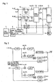
- Fig. 1 is a block diagram illustrating the configuration of one embodiment of an induction motor control apparatus in the present invention.
- Proportional-plus-integral controller 10 performs a control such that a deviation between q-axis current command iq_ref and detected q_axis current value iq_fb becomes zero, and q-axis auxiliary voltage command vq_ref_c is added to the output of proportional-plus-integral controller 10 to create q-axis voltage command vq_ref.
- proportional-plus-integral controller 11 performs a control such that a deviation between d-axis current command id_ref and detected d-axis current value id_fb becomes zero, and d-axis auxiliary voltage command vd_ref_c is added to the output of proportion integration controller 11 to create d-axis voltage command vd_ref.
- a proportional gain of a proportional integrator is represented by Ki, and an integral gain by (1/T).
- Voltage command processor 12 calculates magnitude v_ref and voltage phase ⁇ v of a voltage command from vq_ref and vd_ref, and also adds phase ⁇ phi of magnetic flux to ⁇ v to calculate a voltage phase on three-phase AC coordinates.
- voltage command offset value v_ref_ofs is added to the magnitude v_ref of the voltage command.
- iq_ref, id_ref and fphi are given by separately provided calculation circuits during a normal operating condition of an induction motor.
- Power converter 2 serves to supply induction motor 3 with a three-phase AC voltage based on the above-mentioned v_ref+v_ref_ofs and ⁇ ref.
- Currents flowing into induction motor 3 are detected by current detectors 4 and 5, and fed to coordinate converter 6 where they are converted to iq_fb and id_fb on d_q coordinates.
- iq_fb and id_fb are converted to magnitude i_fb of their composite vector by current processor 7.
- Average and phase difference calculator 8 is a calculator for calculating averages of the voltage command and detected current value as well as a phase difference between the voltage command and detected current value, which are required for calculating a motor constant of induction motor 3, from v_ref+v_ref_ofs and i_fb.
- Motor constant processor 1 is a calculator for calculating the motor constant of induction motor 3 based on signals calculated by average and phase difference calculator 8.
- Fig. 2 illustrates the specific configuration of average and phase difference calculator 8, that calculates, from v_ref_out and i_fb, a phase difference between them, averages of absolute values of respective frequency components, and DC components.
- the average is derived through a low pass filter (LPF), but may be calculated in accordance with a method based on moving average or the like.
- LPF low pass filter
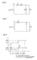
- Fig. 3 illustrates a T-1 type equivalent circuit of an induction motor which is used for determining a motor constant of the induction motor in this embodiment.
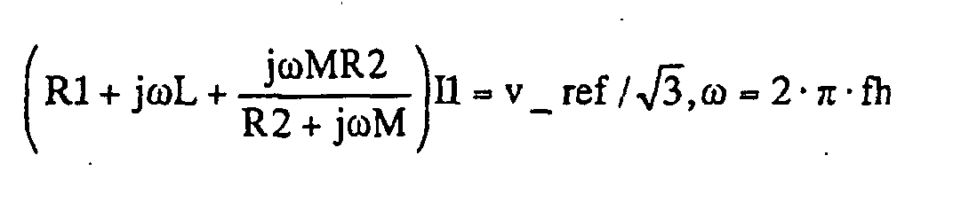
- Fig. 3 is an equivalent circuit for each phase, and is applied with a voltage expressed by: v_ref/ ⁇ 3 I1 is a primary current of the motor; R1 is a primary resistance of the motor; R2 is a secondary resistance of the motor; 1 is a leakage inductance of the motor; and M is a mutual inductance of the motor.
- iq_ref and id_ref are applied as primary current command values arbitrarily set as a current command.
- a voltage command is generated in accordance with the gain of proportional-plus-integral controllers 10, 11, and a three-phase AC voltage is delivered from power converter 2 and applied to motor 3 through which current I1 flows.
- Current I1 is detected by current detectors 4, 5, subjected to coordinate conversion and current processing, and resulting i_fb is applied to motor constant processor 1.
- a time required for the current to rise is determined by the gain of proportional-plus-integral controllers 10, 11, so that this time is set as a previously set arbitrary time, and the proportional gain of the q-axis and d-axis proportional-plus-integral controllers is set to zero after the lapse of the set time. Since this causes zero to be fed to the integrator, the output of the proportional controller is fixed to an output value immediately before the proportional gain is set to zero, thereby stably maintaining the voltage command at a fixed value. Waiting a constant time in this state, averages are measured for voltage command v_ref and detected current value i_fb during the time, and are set to v_ref1 and i_fb1, respectively.
- the present embodiment is a modification of the first embodiment described above, wherein when proportional gain Ki of proportional-plus-integral controllers 10, 11 is set to zero, the q-axis and d-axis voltage commands at that time are substituted into auxiliary voltage command values vq_ref_c and vd_ref_c, respectively, and simultaneously, proportional gain Ki and integral gain (1/T) of proportional-plus-integral controllers 10, 11, and the outputs of proportional-plus-integral controllers 10, 11 are set to zero, such that a resulting voltage command is applied.
- the remaining processing is the same as the first embodiment.
- Vamp is initially set to zero, and fh is set to a value equal to or higher than the rated operation frequency of the motor.
- fh is set to a value equal to or higher than the rated operation frequency of the motor.
- R2 and L can be derived using previously determined R1.
- v_ref shown above is applied, and vamp is gradually increased until average i_fb_ave of the absolute value of the detected current value reaches a previously set first set current value.
- i_fb_ave matches the set value
- average v_ref_ave of the absolute value of a frequency component of v_ref, average i_fb_ave of the absolute value of the detected current value, and phase difference ⁇ dif are stored in a memory as v_ref_ave1, i_fb_ave1, ⁇ dif1, respectively, after waiting for a certain time until the output of the filter becomes stable.
- vamp is adjusted such that average i_fb_ave reaches a previously set second set current value, and the value is similarly read when i_fb_ave matches the second set current value.
- average v_ref_ave, average i_fb_ave and phase difference ⁇ dif are stored as v_ref_ave2, i_fb_ave2, ⁇ dif2, respectively.
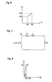
- Fig. 9 shows a change over time in the voltage command and detected current value in this case.
- the present embodiment is a modification of the fourth embodiment, wherein v_ref_ofs is added to voltage command v_ref as an offset value, and the resulting value is used as a voltage command.
- data v_ref_ave, i_fb_ave, ⁇ dif for use in calculating R1+R2 and L can be handled in a similar manner to the fourth embodiment by using data from which a DC component is removed by passing an input signal through a high pass filter.
- the present embodiment is a modification of the fourth embodiment, wherein v_ref_ofs is added to voltage command v_ref as an offset value, and the resulting value is used as a voltage command. Since the voltage equivalent to the offset value is provided as a DC component, an equivalent circuit therefor is that illustrated in Fig. 4, so that primary resistance R1 is determined by calculating the ratio of a DC component of this voltage command value to a DC component of the detected current value. To extract a DC component of a signal, the signal may be averaged. In the embodiment, a low pass filter [LPF3] is used for detection as illustrated in Fig. 2. The value of v_ref_ofs is determined herein by adjusting v_ref_ofs, while comparing the detected current value with the set current value in a manner similar to the fourth embodiment, before an AC signal is applied.
- LPF3 low pass filter
- the sixth embodiment is the same as the embodiment in claim 4 except that R1 thus determined is used for calculating R2. In this way, since R1, R2, L can be determined in a single step, the execution time can be reduced.
- frequency f1 is set at a very low frequency with respect to the rated operation frequency of the motor. In this event, since a current flowing into M cannot be ignored, the equivalent circuit illustrated in Fig. 3 is based on the following discussion.
- v_ref_ofs is added to voltage command v_ref as an offset. Details on the processing are the same as those shown in the fifth and sixth embodiments. Since the frequency is low in the seventh embodiment, the motor can be prevented from unnecessarily moving by applying a DC offset, as shown in this method.
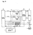
- Fig. 10 illustrates a block diagram in which the invention in claim 10 is implemented. From a configuration for conducting a normal vector control, q-axis voltage command value vq_ref, d-axis voltage command value vd_ref, q-axis detected current value iq_fb, d-axis detected current value id_fb, and output frequency value fphi are extracted and fed to motor constant culculator 1 to calculate mutual inductance M and no-load current value I0.
- Velocity controller 14 calculates q-axis current command value iq_ref, d-axis current command value id_ref and output frequency value fphi based on a velocity command in accordance with a generally used vector control scheme.
- Velocity controller 14 is simplified for description since it does not relate to the features of the present invention.
- Coordinate converter 6 is a coordinate converter for converting a detected phase current value to a value in a dq-coordinate system.
- q-axis PI current controller 10 and d-axis PI current controller 11 are controllers for controlling the current command value to match the detected current value.
- Voltage command calculator 12 calculates magnitude v_ref and voltage phase ⁇ v of a three-phase AC voltage from the q-axis voltage command, d-axis voltage command value, and magnetic flux phase ⁇ phi. Magnetic flux phase ⁇ phi is calculated by integrating output frequency fphi.
- Power converter 2 supplies three-phase AC power to induction motor 3 based on v_ref and ⁇ v.
- the measurements are made upon completion of the acceleration, the measurement may be made at any arbitrary time during operation.
- the method according to the present invention extracts signals from the respective components for calculations in a normal operating condition, and can therefore be applied irrespective of a difference in configuration of the velocity controller due to the presence or absence of PG and the like.
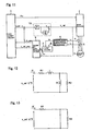
- Fig. 11 is a block diagram illustrating the configuration of a motor control apparatus which implements the method of measuring a motor constant for an induction motor in the eleventh to thirteenth embodiments.
- Motor constant calculator 1 delivers current command i_ref.
- the values of currents flowing into induction motor 3 are captured as current iu detected by current detector 4 for U-phase and current iv detected by current detector 5 for v-phase.
- Three-phase/two-phase converter 6 performs calculations expressed by Equations (1) and (2) to convert iu and iv to two-phase AC currents i ⁇ and i ⁇ .
- iw - (iu + iw)
- the phases at which currents are detected are not limited to a combination of U-phase and v-phase, but the current may be detected at two arbitrary phases or at all the three phases.
- Current calculator 7 calculates a square root of the sum of squared two-phase AC currents i ⁇ , i ⁇ to find detected current value i_fb.
- i_fb is fed to average and phase difference calculator 8 to calculate average i_fb_ave. While the average is herein calculated by taking the absolute value of i_fb and passing the result through a low pass filter, another method such as moving average may be used to calculate the average.
- Current Proportional-plus-integration controller 13 performs a control such that current command i_ref matches average detected current value i_fb_ave.
- the output of current Proportional-plus-integration controller 13 is voltage command v_ref.
- Power converter 2 converts voltage command value v_ref into a line-to-line voltage, calculates the output phase of a three-phase AC current using voltage phase ⁇ v applied from motor constant calculator 1, and supplies induction motor 3 with three-phase AC power.
- Fig. 12 illustrates a T-1 type equivalent circuit for one phase of an induction motor.
- R1 represents a primary resistance;
- L a leakage inductance;
- M a mutual inductance;
- R2 a secondary resistance; and s a slippage.
- an impedance component of mutual inductance M is zero, so that the equivalent circuit is changed as illustrated in Fig. 13.
- voltage phase ⁇ v is at 0°.
- v_ref_ave which is an average of v_ref
- i_fb_ave which is an average of i_fb
- v_ref_ave is calculated by feeding the value of v_ref to average and phase difference calculator 8.
- 40 % of the rated current of the induction motor is applied as current command i ref, and a similar control is conducted.
- 2xR1 is set to line-to-line resistance value RL-L. While the current value is set herein to 20 % and 40 % of the rated current of the induction motor, different values may be used, or the foregoing operation may be performed at three points or more of the current value.
- measurements at three points or more are made.
- the slopes are calculated respectively between 20 % and 40 %, between 40 % and 60 % and between 20 % and 60 %.
- the slopes may be averaged for use.
- the previously measured data is approximated by a linear function and extended for recording the value of v_ref when the current value is zero, as voltage offset value v_ref0.
- This corresponds to a voltage drop caused by devices used for power converter 2 and the like.
- the voltage offset value may be found by linear approximation of two arbitrary points or a regression curve based on a mean square error method.
- FIGs. 16 and 17 are block diagrams for implementing methods described in claims 14 and 15.
- output voltage command v_ref and output voltage phase ⁇ v are applied from motor constant calculator 1 to power converter 2 to supply a three-phase AC current based thereon for operating induction motor 3.
- the value of the current flowing into induction motor 3 is captured as current iu detected by current detector 4 for U-phase and current iv detected by current detector 5 for v-phase.
- Coordinate converter 6 performs the calculations expressed by Equations (1) and (2) to convert iu and iv to two-phase AC currents i ⁇ and i ⁇ .
- the phases at which the currents are detected are not limited to a combination of U-phase and v-phase, but the current may be detected at two arbitrary phases or at all the three phases.
- Current calculator 7 calculates a square root of the sum of squared two-phase AC currents i ⁇ , i ⁇ to find detected current value i_fb.
- Voltage command v_ref, detected current value i_fb, and phase ⁇ h at which an instantaneous value of the amplitude is given for v_ref applied by motor constant calculator 1 are fed to average and phase difference processor 8 which calculates v_ref_ave which is an average of v_ref, i_fb_ave which is an average of i_fb, and phase difference ⁇ dif which are fed to motor constant calculator 1 for calculating a motor constant.
- Fig. 17 is a block diagram illustrating the configuration of average and phase difference calculator 6.
- Average and phase difference processor 6 calculates v_ref, i_fb_ave which is an average of i_ref, and phase difference ⁇ dif based on the processing in the block diagram of Fig. 17.
- the equivalent circuit of the induction motor illustrated in Fig. 12 can be approximated to a series circuit of R1, L, R2 as illustrated in Fig. 18 because impedance ⁇ M by mutual inductance M becomes larger as compared with R2 at higher frequencies. Therefore, resistance component R1+R2 and reactance component ⁇ L are determined from the magnitudes of the voltage and current, and the phase difference between them.
- ⁇ v is set to 0°; first frequency fh1 to 15 Hz; second frequency fh2 to 30 Hz; and the set current value described in the fourteenth embodiment to 80 % of the rated current of the induction motor.
- Voltage amplitude Vamp is adjusted while i_fb is monitored such that average detected current value i_fb reaches 80 % of the rated current of the induction motor.
- Vamp should be adjusted by an appropriate step which does not cause the current to suddenly change.
- a step equal to 1/1000 of the rated voltage of the induction motor was added to or subtracted from Vamp.
- an average of the absolute value of magnitude v_ref of the voltage command is set to v_ref_ave1; an average of the absolute value of the magnitude of detected current value i_fb to i_fb_ave1; and the phase of i_fb with respect to v_ref to ⁇ dif1 after the lapse of an arbitrarily set time (here three seconds).
- the frequency is set to 30 Hz at which a similar operation is performed to that at 15 Hz.
- an average of the absolute value of magnitude v_ref of the voltage command is set to v_ref_ave2; an average of the absolute value of the magnitude of detected current value i_fb to i_fb_ave2; and the phase of i_fb with respect to v_ref to ⁇ dif2.
- respective saturated values are fed to low pass filters, the outputs of which are used for the averages.
- a time chart of the voltage command and detected current value at this time is shown in Fig. 19.
- Zx1 (v_ref_ave1/ ⁇ 3)/(i_fb_ave1)
- Zx2 (v_ref_ave2/ ⁇ 3)/(i_fb_ave2)
- Zxr1 Zx1 ⁇ cos ⁇ dif_1
- Zxr2 Zx2 ⁇ cos ⁇ dif_2
- Zxi1 Zx1 ⁇ sin ⁇ dif_1
- Zxi2 Zx2 ⁇ sin ⁇ dif_2
- fh2 is used because the voltage value becomes larger at a higher frequency, resulting in a reduction in measurement error.
- the lower frequency may be used, or the leakage inductance may be calculated from the slope at two frequencies.
- Zx1 (v_ref_ave1/ ⁇ 3-v_ref0)/(i_fb_ave1)
- Zx2 (v_ref_ave2/ ⁇ 3-v_ref0)/(i_fb_ave2)
- i_fb2 is set to 40 % of the rated current of the motor (one half of the foregoing), and an average of the absolute value of the voltage command value at 15 Hz is set to v_ref_ave3; an average of the absolute value of the detected current value at 15 Hz to i_fb_ave3; and an average of the voltage command value at 30 Hz to v_ref_ave4; and an average of the absolute value of the detected current value at 30 Hz to i_fb_ave4.
- linear approximation is made with two current values at 15Hz, 30 Hz, respectively, and the values at the current value equal to zero are derived as voltage offset v_ofs15 at 15 Hz and voltage offset v_ofs30 at 30 Hz.
- these offset values may be used for the voltage command values at 15 Hz, 30 Hz instead of voltage offset value v_ref0 in the thirteenth embodiment to compensate for the voltage offset.
- the impedances may be calculated at 15 Hz, 30Hz, respectively, from the slope when the current value is changed.
- an average value of two current values may be used for the phase to calculate a real part and an imaginary part of the impedance.
- voltage value offset value v_ref0 described in the embodiment of claim 13 is derived from a DC value and therefore is an effective value or a maximum value, so that v_ref0 is converted to an average which is used. While the average is used herein, any of the effective value, average, maximum value may be used as long as the conversion associated therewith is consistent.
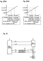
- Fig. 23 is a block diagram illustrating the configuration of an apparatus for implementing a method of measuring a motor constant for an induction motor in a sixteenth and a seventeenth embodiment of the present invention.
- power converter 2 converts voltage command v_ref and voltage phase ⁇ v applied from motor constant calculator 1 to three-phase AC power which is supplied to induction motor 3.
- the values of currents flowing into induction motor 3 are captured as current iu detected by current detector 4 for U-phase and current iv detected by current detector 5 for v-phase.
- Coordinate converter 6 performs the calculations expressed by Equations (1) and (2) to convert iu and iv to two-phase AC currents i ⁇ and i ⁇ .
- Equation (2) the multiplication by (2/3) is intended for equaling the magnitude of the amplitude before and after the conversion.
- the phases at which the currents are detected are not limited to a combination of the U-phase and v-phase, but the currents may be detected at arbitrary two phases or at all the three phases.
- Two-phase AC currents i ⁇ and i ⁇ are fed to motor constant calculator 1 which calculates detected primary current value i1 as a square root of the sum of squared two-phase AC currents i ⁇ , i ⁇ .
- Fig. 23 shows an inverter-based motor driving apparatus from which parts required for practicing the present invention are extracted, wherein blocks such as velocity control, current control and the like disposed prior to voltage command and output voltage phase are replaced by motor constant calculator 1 during a normal operation in a conventional method of identifying a motor constant. Both are switched by an additional switch.
- R1 represents a primary resistance;
- L a leakage inductance;
- R2 a secondary resistance;
- M a mutual inductance;
- v an applied voltage;
- i1 a primary current of the motor;
- i2 a secondary current of the motor; and
- im a current (excited current) flowing through mutual inductance M.
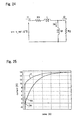
- No-load current I0 is a current which flows when the induction motor is applied with the power at the rated voltage and rated frequency and rotated without load, in which case an equivalent circuit is represented by a series circuit of R1, L, M in the form of T-1 type equivalent circuit in Fig. 24.
- V, I are values indicative of the magnitudes of the voltage and current, respectively, and may be any of effective values, maximum values or averages as long as the same one is employed for the voltage and current.
- I0 v R1 2 + ⁇ 2 (L + M) 2 no-load current I0 is calculated.
- R1 and L are taken into consideration in Equations (16), (18), (19), R1 and L may be ignored for simplification.
- Fig. 25 shows the waveform of a change over time of estimate ⁇ m of im calculated in accordance with Equation (15) using primary current i1 when voltage v equal to V1 is applied stepwise, current im flowing through mutual inductance, primary current i1, and R1, R2.
- I1 ⁇ to which i1, im, ⁇ m converge is (V1/R1), and the waveform of ⁇ m changing from 0 to i1 ⁇ can be confirmed to substantially match the waveform of im. Therefore, time constant ⁇ andm may be determined from a change in im at this time.
- voltage phase ⁇ v was set at 0° for implementation.
- the value of v_ref at this time is stored as V1, and the power supplied to motor 3 is shut off.
- the increment for the voltage command may be arbitrarily set at such a magnitude that does not cause a sudden change in the current.
- a current controller is provided, 50 % of the rated current is applied as the current command.
- the current command value at this time may be set to V1.
- a current value and a voltage command value at that time may be used.
- the current value may be set at a value other than 50 % of the rated current.
- V1 is applied as voltage command v_ref
- induction motor 3 is applied with a voltage stepwise.
- Primary current il is measured at this time, and ⁇ m is calculated in accordance with the aforementioned Equation (15).
- v corresponds to v_ref
- Values used for R1, R2 are given by a test result table of the induction motor or another existent identifying means.
- Time constant ⁇ is determined from the waveform of rising im, and the value at this time is designated by ⁇ and im .
- ⁇ andm is substituted into ⁇ shown in Equation (12) to calculate mutual inductance M. While time constant ⁇ andm is generally determined by measuring a time for ⁇ m to reach from zero to a final (convergence) value (1-1/e) ⁇ 0.632, measurements may be made on a change in the current at an arbitrary current value and on a time during the change, and conversion may be made to match this time with the time constant. In the latter case, measurements can be made at a plurality of points, thereby making it possible to reduce variations by measuring several data and averaging the data.
- no-load current I0 Vrate R1 2 + (2 ⁇ frate) 2 (L + M) 2
- L and R1 may be omitted in the calculation for simplification.
- the measurement can be made independently of a voltage accuracy of the driving apparatus.
- the value used for i 1 ⁇ may be a current value which is read upon measurement of the resistance.
- a nineteenth embodiment carries out the seventeenth embodiment using the method of calculating ⁇ m in the eighteenth embodiment.
Landscapes
- Physics & Mathematics (AREA)
- General Physics & Mathematics (AREA)
- Control Of Ac Motors In General (AREA)
- Tests Of Circuit Breakers, Generators, And Electric Motors (AREA)
Abstract
Description

Voltage command calculator 12 calculates magnitude v_ref and voltage phase v of a three-phase AC voltage from the q-axis voltage command, d-axis voltage command value, and magnetic flux phase phi. Magnetic flux phase phi is calculated by integrating output frequency fphi. Power converter 2 supplies three-phase AC power to induction motor 3 based on v_ref and v.

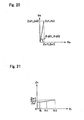
(fh=fh1·fh2/(fh1+fh2)=15·30/(15+30)) is as'Zxr through linear approximation of measured values as shown in Fig. 21. Next, consider the imaginary components. Since the imaginary components are substantially proportional to the frequency component, the leakage inductance is calculated in accordance with L=Zxi/(2·π·fh_1) using the values at fh2 (30 Hz), where Zxi=Zxi2 and fh_1=fh2. Here, fh2 is used because the voltage value becomes larger at a higher frequency, resulting in a reduction in measurement error. The lower frequency may be used, or the leakage inductance may be calculated from the slope at two frequencies.
Claims (19)
- A method of measuring a motor constant for an induction motor in a motor vector control apparatus having a d-axis current proportional-plus-integral controller which receives a current command for a d-axis component of a primary current of the motor and a detected current value of the d-axis component for controlling a deviation between both to reduce to zero; a first adder for adding an output of said proportional-plus-integral controller and an arbitrary d-axis auxiliary voltage command value to derive a d-axis voltage command value; a q-axis current proportional-plus-integral controller which receives a current command for a q-axis component of the primary current of the motor and a detected current value of the q-axis component for controlling a deviation between both to reduce to zero; a second adder for adding an output of said proportional-plus-integral controller and an arbitrary q-axis auxiliary voltage command value to derive a q-axis voltage command value; and a power converter for calculating a magnitude v_ref and a voltage phase v of a voltage command from the d-axis voltage command value and the q-axis voltage command value, and converting a DC current to a three-phase AC current based on the magnitude of the voltage command and the phase of the voltage command to output the three-phase AC current, said vector control apparatus being configured to convert the motor to an equivalent circuit of a three-phase Y (star) connection for handling and controlling the motor, said method comprising the steps of:applying a d-axis current command value id_ref1 and a q-axis current command value iq_ref1 previously set at arbitrary fixed values as first command values, and applying the d-axis auxiliary voltage command vd_ref_c and the q-axis auxiliary voltage command value vq_ref_c both set at zero to operate said vector control apparatus;after the lapse of a previously set first time, setting a proportional gain of the d-axis proportional-plus-integral controller and a proportional gain of the q-axis proportional-plus-integral controller to zero, and after the lapse of a previously set second time from this time, creating the voltage command:setting an average of v_ref and an average of i_fb recorded within an arbitrary time during the second time as first data v_ref1, i_fb1, respectively;returning the gains of both said proportional-plus-integral controllers to original values, applying a d-axis current command value id_ref2 and a q-axis current command value iq_ref2 previously set at arbitrary fixed values as second command values, and applying the d-axis auxiliary voltage command value vd_ref_c and the q-axis auxiliary voltage command value vq_ref_c set at zero to operate said vector control apparatus;after the lapse of the previously set first time, setting the proportional gain of the d-axis proportional-plus-integral controller and the proportional gain of the q-axis proportional-plus-integral controller to zero, and after the lapse of a previously set second time from this time, calculating a primary resistance of the motor in accordance with:
- The method according to claim 1, including, after the lapse of the first time:setting the output of the d-axis current proportional-plus-integral controller to the d-axis auxiliary voltage command value, and simultaneously setting the proportional gain and integral gain of the d-axis current proportional-plus-integral controller and the output of the d-axis current proportional-plus-integral controller to zero;setting the output of the q-axis current proportional-plus-integral controller to the q-axis auxiliary voltage command value, and simultaneously setting the proportional gain and integral gain of the q-axis current proportional-plus-integral controller and the output of the q-axis current proportional-plus-integral controller to zero; andperforming the operation after the lapse of said first time in a similar manner.
- The method according to claim 1 or 2, wherein three or more levels are provided for the d-axis current command value and the q-axis current command value previously set at arbitrary fixed values, and the primary resistance is calculated as an average of the values of the primary resistance calculated in respective intervals.
- A method of measuring a motor constant for an induction motor in a motor vector control apparatus having a d-axis current proportional-plus-integral controller which receives a current command for a d-axis component of a primary current of the motor and a detected current value of the d-axis component for controlling a deviation between both to reduce to zero; a first adder for adding an output of said proportional-plus-integration controller and an arbitrary d-axis auxiliary voltage command value to derive a d-axis voltage command value; a q-axis current proportional-plus-integral controller which receives a current command for a q-axis component of the primary current of the motor and a detected current value of the q-axis component for controlling a deviation between both to reduce to zero; a second adder for adding an output of said proportional-plus-integral controller and an arbitrary q-axis auxiliary voltage command value to derive a q-axis voltage command value; and a power converter for calculating a magnitude v_ref and a voltage phase v of a voltage command from the d-axis voltage command value and the q-axis voltage command value, and converting a DC current to a three-phase AC current based on the magnitude of the voltage command and the phase of the voltage command to output the three-phase AC current, said vector control apparatus being configured to convert the motor to an equivalent circuit of a three-phase Y (star) connection for handling and controlling the motor, said method comprising the steps of:setting gains and outputs of both said proportional-plus-integral controllers, the d-axis auxiliary voltage command and the q-axis auxiliary voltage command to zero, setting a voltage phase v to a previously set arbitrary fixed value, and giving a magnitude vref of the voltage command by v_ref=vamp·sin(2· π·fh·t), where fh is a frequency 1/10 or more as high as a rated operation frequency of the motor, and vamp is a voltage amplitude;incrementally or decrementally adjusting vamp while monitoring a current value i_fb such that:after i_fb reaches said first set current value, setting an average of an absolute value of the magnitude v_ref of the voltage command to v_ref_avel, an average of an absolute value of the magnitude of the detected current value i_fb to i_fb_avel, and the phase of i_fb with respect to v_ref dif1 after the lapse of an arbitrarily set time;adjusting vamp to reach a previously set second set current value, and setting the average of the absolute value of the magnitude v_ref of the current command to v_ref_ave2, the average of the absolute value of the magnitude of the detected current value i_fb to i_fb_ave2, and the phase of i_fb with respect to v_ref to dif2 after the lapse of said set time;calculating:from this, calculating a secondary resistance of the motor in accordance with R2=Zx_r-R1, and a leakage inductance in accordance with L=Zx_i/(2·π·fh).
- The method according to claim 4, including adding a DC offset component v_ref_ofs to the voltage command value to apply the voltage command expressed by v_ref=vamp·sin(2·π·fh·t)+v_ref_ofs, feeding the detected current value i_fb to a high pass filter designed to filter out a DC component and pass a signal having an fh component therethrough to use an output of the high pass filter as new i_fb, feeding v_ref to a high pass filter having the same characteristics as that used for i_fb in a similar manner, and calculating the secondary resistance R2 and the leakage inductance L of the motor in accordance with said equation using the output of the high pass filter as new v_ref.
- The method according to claim 5, including calculating the primary resistance:
- A method of measuring a motor constant for an induction motor in a motor vector control apparatus having a d-axis current proportional-plus-integral controller which receives a current command for a d-axis component of a primary current of the motor and a detected current value of the d-axis component for controlling a deviation between both to reduce to zero; a first adder for adding an'output of said proportional-plus-integration controller and an arbitrary d-axis auxiliary voltage command value to derive a d-axis voltage command value; a q-axis current proportional-plus-integral controller which receives a current command for a q-axis component of the primary current of the motor and a detected current value of the q-axis component for controlling a deviation between both. to reduce to zero; a second adder for adding an output of said proportional-plus-integral controller and an arbitrary q-axis auxiliary voltage command value to derive a q-axis voltage command value; and a power converter for calculating a magnitude v_ref and a voltage phase v of a voltage command from the d-axis voltage command value and the q-axis voltage command value, and converting a DC current to a three-phase AC current based on the magnitude of the voltage command and the phase of the voltage command to output the three-phase AC current, said vector control apparatus being configured to convert the motor to an equivalent circuit of a three-phase Y (star) connection for handling and controlling the motor, said method comprising the steps of:setting gains and outputs of both said proportional-plus-integral controllers, the d-axis auxiliary voltage command and the q-axis auxiliary voltage command to zero, setting a voltage phase v to a previously set arbitrary fixed value, and giving a magnitude vref of the voltage command by v_ref=vamp·sin(2· π·fl·t), where fl is a frequency 1/5 or less as high as a rated operation frequency of the motor, and vamp is a voltage amplitude;incrementally or decrementally adjusting vamp while monitoring a current value i_fb such that:after i_fb reaches said first set current value, setting an average of an absolute value of the magnitude v_ref of the voltage command to v_ref_ave3, an average of an absolute value of the magnitude of the detected current value i_fb to i_fb_ave3, and the phase of i_fb with respect to v_ref to dif3 after the lapse of a first arbitrary set time;adjusting vamp to reach a previously set second set current value, and setting the average of the absolute value of the magnitude v_ref of the current command to V_ref_ave4, the average of the absolute value of the magnitude of the detected current value i_fb to i_fb_ave4, and the phase of i_fb with respect to v_ref to dif4 after the lapse of said first set time;calculating:from this, calculating a mutual inductance of the motor in accordance with:
- The method according to claim 7, including adding a DC offset component v_ref_ofs to the voltage command value to apply the voltage command expressed by v_ref=vamp·sin(2·π·fl·t)+v_ref_ofs, feeding the detected current value i_fb to a high pass filter designed to filter out a DC component and pass a signal having an fh component therethrough to use an output of the high pass filter as new i_fb, feeding v_ref to a high pass filter having the same characteristics as that used for i_fb in a similar manner, and calculating the mutual inductance M of the motor in accordance with said calculation equation using the output of the high pass filter as new v_ref.
- The method according to claim 8, including calculating the primary resistance:
- A method of measuring a motor constant for an induction motor in a motor control apparatus having a' d-axis current proportional-plus-integral controller which receives a current command for a d-axis component of a primary current of the motor and a detected current value of the d-axis component for controlling a deviation between both to reduce to zero; a q-axis current proportional-plus-integral controller which receives a current command for a q-axis component of the primary current of the motor and a detected current value of the q-axis component for controlling a deviation between both to reduce to zero; and a power converter for calculating a magnitude v_ref and a voltage phase v of a voltage command from the d-axis voltage command value which is an output of said d-axis current proportional-plus-integral controller and the q-axis voltage command value which is an output of said q-axis current proportional-plus-integral controller, and converting a DC current to a three-phase AC current based on the magnitude of the voltage command and the phase of the voltage command to output the three-phase AC current, said vector control apparatus being configured to control the d-axis current command and the q-axis current command to operate the motor in conformity with an arbitrary velocity command, said method comprising the step of:calculating:
- A method of measuring a motor constant for an induction motor in a motor control apparatus configured to supply a three-phase AC current to the induction motor through an inverter to operate the motor at a variable velocity, said motor control apparatus having a current detector for detecting the current flowing at two arbitrary phases or three phases of an inverter output; a proportional-plus-integral controller which receives a current command value for a primary current fed to the motor, and a primary current value i_fb of a primary current detector derived from a current value detected by said current detector to control an output voltage command value v_ref such that a deviation between both reduces to zero; and a power converter for outputting a three-phase AC current based on the voltage command value v_ref and a voltage output phase v, said motor control apparatus being configured to convert the motor to an equivalent circuit of a three-phase Y (star) connection for handling the equivalent circuit, said method comprising the steps of:operating said proportional-plus-integral controller by setting a previously set arbitrary phase to the voltage output phase v, and applying a current command value i_ref1 previously set at an arbitrary fixed value as a first command value;after the lapse of a previously set first time, setting a proportional gain of said proportional-plus-integral controller to zero, and after the lapse of a previously set second time from this time, setting an average of v_ref and an average of i_fb within an arbitrary time during the second time to first data v_ref1, i_fb1, respectively;operating said proportional-plus-integral controller by returning the gain of said proportional-plus-integral controller to an original value, and applying a current command value i_ref2 previously set at an arbitrary fixed value as a second command value;after the lapse of the previously set first time, setting the proportional gain of said proportional-plus-integral controller to zero, and after the lapse of a previously set second time from this time, setting an average of v_ref and an average of i_fb recorded within an arbitrary time during the second time to second data v_ref2, i_fb2, respectively; andcalculating a primary resistance R1 of the motor in accordance with:
- The method according to claim 11, wherein three or more levels are provided for the current command value previously set at the arbitrary fixed value, and the primary resistance value is calculated as an average of the values of the primary resistance calculated in respective intervals.
- The method according to claim 11, wherein the current command value v_ref0 when the detected current value if_fb is zero is calculated from a linear equation derived from the measured values v_ref1, i_fb1, v_ref2 and i_fb2, and set to a voltage offset value.
- A method of measuring a motor constant for an induction motor in a motor control apparatus configured to supply three-phase AC to the induction motor through an inverter to operate the motor at a variable velocity, said motor control apparatus having current detectors disposed in two arbitrary phases or three phases of an inverter output, a proportional-plus-integral controller which receives a current command value for a primary current fed to the motor, and a primary current value i_fb of a primary current detector derived from current values detected by said current detectors to control an output voltage command value v_ref such that a deviation between both reduces to zero; and a power converter for outputting a three-phase AC current based on the voltage command value v_ref and a voltage output phase v, said motor control apparatus being configured to convert the motor to an equivalent circuit of a three-phase Y (star) connection for handling the equivalent circuit, said method comprising the steps of:setting the voltage phase v at a previously set arbitrary fixed value, and giving a magnitude vref of a voltage command by v_ref=vamp·sin(2·π·fh1·t), where fhl is a frequency 1/10 or more as high as a base operation frequency of the motor, and vamp is a voltage amplitude;incrementally or decrementally adjusting vamp while monitoring the detected current value i_fb such that i_fb reaches a previously arbitrarily set current value;after i_fb reaches said set current value, setting an average of an absolute value of the magnitude v_ref of the voltage command to v_ref_ave1, an average of an absolute value of the magnitude of the detected current value i_fb to i_fb_abe1, and the phase of i_fb with respect to v_ref to dif1 after the lapse of an arbitrarily set time;setting the frequency to a frequency fh2 1/10 or more higher than the base operation frequency of the motor and different from fh1, adjusting vamp to reach said set current value, and after the lapse of said set time, setting the average of the absolute value of the magnitude v_ref of the current command to v_ref_ave2, the average of the absolute value of the magnitude of the detected current value i_fb to i_fb_ave2, and the phase of i_fb with respect to v_ref to dif_2;calculating:calculating the value of Zxr when the frequency fh is at fh1·fh2/(fh1+fh2) from a linear equation derived using Zxr1 when the frequency is at fh1 and Zxr2 when the frequency is at fh2, and calculating a secondary resistance of the motor using the value of Zxr and the primary resistance R1 of the motor in accordance with R2=Zxr-R1; andcalculating a leakage inductance in accordance with L=Zxi/(2·π·fh_1), where fh_1 represents the higher frequency of fh1 and fh2, and Zxi represents the value of Zxi at this time.
- The method of measuring a motor constant for an induction motor according to claim 14, including:establishing:
- A method of measuring a motor constant for an induction motor in a motor control apparatus configured to supply a three-phase AC current to the induction motor through an inverter to operate the induction motor at a variable velocity, said motor control apparatus having a power converter for delivering a three-phase AC current based on an output voltage command value v_ref and a voltage output phase v, and a current detector for detecting a primary current flowing into the induction motor, said motor control apparatus receiving a detected primary current value il derived from a current value detected by said current detector, said method comprising the steps of:creating an equivalent circuit per phase of the induction motor in the form of T-1 type equivalent circuit;setting a previously set arbitrary fixed value to the voltage phase v and a predetermined fixed value to the voltage command v_ref, reading the detected primary current value il flowing into the induction motor in this event, and estimating a current im flowing through a mutual inductance M in accordance with:using said primary current value i1 and a primary resistance value R1 and a secondary resistance value R2 given by an additional means;
 determining a time constant τ andm from the waveform of the estimate ím(t) of the rising current; andcalculating the mutual inductance M in accordance with:
 - The method of measuring a motor constant for an induction motor according to claim 16, including calculating a no-load current I0 using the mutual inductance M or the time constant τ andm, the primary resistance value R1, a leakage inductance L and the secondary resistance value R2 given by an additional means, a rated voltage Vrate and a rated frequency frate given as the rating of the motor, and said mutual inductance M.
- A method of measuring a motor constant for an induction motor in a motor control apparatus configured to supply a three-phase AC current to the induction motor through an inverter to operate the induction motor at a variable velocity, said motor control apparatus having a power converter for delivering a three-phase AC current based on an output voltage command value v_ref and a voltage output phase v, and a current detector for detecting a primary current flowing into the induction motor, said motor control apparatus receiving a detected primary current value i1 derived from a current value detected by said current detector, said method comprising the steps of:creating an equivalent circuit per phase of the induction motor in the form of T-1 type equivalent circuit;setting a previously set arbitrary fixed value to the voltage phase v and a predetermined fixed value to the voltage command v_ref, reading the detected primary current value il flowing into the induction motor in this event, and estimating a current im flowing through a mutual inductance M using said primary current value i1, and a primary resistance value R1 and a secondary resistance value R2 given by an additional means in accordance with:determining a time constant τ andm from the waveform of the estimate ím(t) of the rising current; andcalculating the mutual inductance M in accordance with:
- The method for an induction motor according to claim 18, including calculating a no-load current I0 using the calculated mutual inductance M or the time constant τ andim, the primary resistance value R1, a leakage inductance L and the secondary resistance value R2 given by an additional means, a rated voltage Vrate and a rated frequency frate given as the rating of the motor, and said mutual inductance M.
Applications Claiming Priority (3)
| Application Number | Priority Date | Filing Date | Title |
|---|---|---|---|
| JP2000212896A JP4816838B2 (en) | 2000-07-13 | 2000-07-13 | Vector control device for induction motor |
| JP2000212896 | 2000-07-13 | ||
| PCT/JP2001/005844 WO2002006843A1 (en) | 2000-07-13 | 2001-07-05 | Method for measuring motor constant of induction motor |
Publications (3)
| Publication Number | Publication Date |
|---|---|
| EP1312932A1 true EP1312932A1 (en) | 2003-05-21 |
| EP1312932A4 EP1312932A4 (en) | 2005-07-06 |
| EP1312932B1 EP1312932B1 (en) | 2006-10-25 |
Family
ID=33312515
Family Applications (1)
| Application Number | Title | Priority Date | Filing Date |
|---|---|---|---|
| EP01947850A Expired - Lifetime EP1312932B1 (en) | 2000-07-13 | 2001-07-05 | Method for measuring motor constant of induction motor |
Country Status (8)
| Country | Link |
|---|---|
| US (1) | US7039542B2 (en) |
| EP (1) | EP1312932B1 (en) |
| JP (1) | JP4816838B2 (en) |
| KR (1) | KR100773282B1 (en) |
| CN (1) | CN1180275C (en) |
| DE (1) | DE60124114T2 (en) |
| TW (1) | TW544524B (en) |
| WO (1) | WO2002006843A1 (en) |
Cited By (2)
| Publication number | Priority date | Publication date | Assignee | Title |
|---|---|---|---|---|
| US7265954B2 (en) | 2003-10-24 | 2007-09-04 | Daikin Industries, Ltd. | Method for estimating DC motor coil temperature, DC motor control method and their devices |
| CN100423446C (en) * | 2005-08-11 | 2008-10-01 | 株式会社日立制作所 | Vector Control Device of Permanent Magnet Synchronous Motor |
Families Citing this family (40)
| Publication number | Priority date | Publication date | Assignee | Title |
|---|---|---|---|---|
| US6763622B2 (en) * | 2002-10-10 | 2004-07-20 | General Motors Corporation | Amplitude detection method and apparatus for high frequency impedance tracking sensorless algorithm |
| US7408322B2 (en) * | 2003-06-06 | 2008-08-05 | Mitsubishi Denki Kabushiki Kaisha | Device for determining constant of rotating machine |
| JP4455245B2 (en) * | 2004-09-22 | 2010-04-21 | 三菱電機株式会社 | Vector control device for induction motor |
| CN100492044C (en) * | 2005-01-06 | 2009-05-27 | 三菱电机株式会社 | Method for measuring constant of rotating electric machine |
| JP4881635B2 (en) * | 2006-03-15 | 2012-02-22 | 株式会社日立製作所 | Vector controller for permanent magnet motor |
| JP2008086129A (en) * | 2006-09-28 | 2008-04-10 | Hitachi Ltd | AC motor control device and constant measuring device |
| JP5107581B2 (en) * | 2007-01-12 | 2012-12-26 | 三菱電機株式会社 | Electric vehicle control device |
| JP5146925B2 (en) * | 2007-12-18 | 2013-02-20 | 株式会社安川電機 | Induction motor control device and motor constant measurement calculation method thereof |
| CN102754331B (en) * | 2009-11-25 | 2014-12-03 | 三菱电机株式会社 | Electric vehicle power conversion device |
| KR101142973B1 (en) * | 2010-02-23 | 2012-05-08 | 고려대학교 산학협력단 | Apparatus and method for diagnosing electrical contact quality of motor, and a medium having computer readable program for executing the method |
| WO2012077153A1 (en) * | 2010-12-06 | 2012-06-14 | 三菱電機株式会社 | Inductance measurement device and measurement method for synchronous electric motor |
| CN102545735A (en) * | 2010-12-20 | 2012-07-04 | 上海大郡动力控制技术有限公司 | Method for processing current static deviation of permanent magnet motor |
| JP5633640B2 (en) * | 2011-04-21 | 2014-12-03 | 日産自動車株式会社 | Electric motor control device and electric motor control method |
| JP5909658B2 (en) * | 2011-08-03 | 2016-04-27 | パナソニックIpマネジメント株式会社 | Motor constant calculation method and motor constant calculation apparatus for permanent magnet type synchronous motor |
| CN103959642B (en) * | 2011-11-29 | 2016-08-17 | 三菱电机株式会社 | Control device for rotating machine and method for measuring inductance of rotating machine |
| US9172318B2 (en) * | 2013-03-05 | 2015-10-27 | Steering Solutions Ip Holding Corporation | Method and system to compensate for dynamic DC offset of measured phase current |
| US8947034B2 (en) * | 2013-03-14 | 2015-02-03 | Regal Beloit America, Inc. | Methods and systems for controlling an electric motor |
| JP6194718B2 (en) * | 2013-09-20 | 2017-09-13 | サンケン電気株式会社 | Constant measuring apparatus and constant measuring method for induction motor |
| JP6165575B2 (en) * | 2013-09-30 | 2017-07-19 | 株式会社日立産機システム | Power converter |
| KR101535727B1 (en) * | 2013-11-29 | 2015-07-09 | 엘에스산전 주식회사 | Apparatus for controlling induction machine |
| CN105450119B (en) * | 2014-08-29 | 2018-08-10 | 伊顿公司 | Accelerated method of the induction machine of V/f controls in weak magnetic area |
| JP6045765B1 (en) * | 2015-05-20 | 2016-12-14 | 三菱電機株式会社 | Power conversion device and vehicle drive system using the same |
| CN105116331B (en) * | 2015-09-08 | 2017-11-17 | 哈尔滨工业大学 | The method of testing of motor under a kind of high temperature and high pressure environment |
| CN105116332B (en) * | 2015-09-08 | 2017-11-17 | 哈尔滨工业大学 | The method of testing of motor under a kind of high-temperature low-pressure environment |
| CN105182235B (en) * | 2015-09-08 | 2017-09-19 | 哈尔滨工业大学 | The method of testing of motor under a kind of low-temp low-pressure environment |
| US9673743B1 (en) | 2016-09-08 | 2017-06-06 | Limiter Power Management System (PTY) LTD. | Efficient motor control |
| CN106385214B (en) * | 2016-09-29 | 2019-08-13 | 东南大学 | High-speed permanent magnetic synchronous motor control method based on Modular multilevel converter |
| CN108847800B (en) * | 2018-06-28 | 2020-05-05 | 闽江学院 | Off-line identification method for resistance inductance parameters of surface-mounted permanent magnet synchronous motor |
| JP7396283B2 (en) * | 2018-08-08 | 2023-12-12 | ニデック株式会社 | Failure detection method for motor drive device, electric oil pump, and motor drive device |
| KR102113497B1 (en) * | 2018-09-07 | 2020-05-28 | 동명대학교산학협력단 | Potable Rotor Diagnosis Device And Method for Induction Machines |
| CN110221207A (en) * | 2019-07-02 | 2019-09-10 | 宁波奥克斯电气股份有限公司 | A kind of device and method for testing PG motor feedback circuit |
| CN110601639B (en) * | 2019-08-20 | 2021-02-26 | 瑞声科技(新加坡)有限公司 | Signal equalization method and device based on motor vibration acceleration and storage medium |
| JP7272909B2 (en) * | 2019-08-30 | 2023-05-12 | 株式会社安川電機 | Power conversion device and power conversion method |
| TWI713298B (en) * | 2019-09-05 | 2020-12-11 | 台達電子工業股份有限公司 | Electric machine control system and control method thereof |
| CN114600367A (en) * | 2019-11-01 | 2022-06-07 | 三菱电机株式会社 | Motor inductance measuring device, motor drive system and motor inductance measuring method |
| US11081994B1 (en) * | 2020-02-20 | 2021-08-03 | Renesas Electronics Corporation | Semiconductor device and motor control system |
| CN112600475B (en) * | 2020-12-30 | 2023-02-28 | 广东美的白色家电技术创新中心有限公司 | Field-weakening control method, field-weakening control device, motor driver and household appliance |
| CN116500437B (en) | 2022-01-18 | 2026-03-06 | 台达电子工业股份有限公司 | Inductance detection method and motor testing device for reluctance motors |
| EP4216425B1 (en) * | 2022-01-20 | 2024-11-06 | Abb Schweiz Ag | Estimating at least one leakage inductance of a multi-phase electrical machine |
| JP7638448B2 (en) * | 2022-05-16 | 2025-03-03 | 三菱電機株式会社 | Power conversion device, refrigeration cycle device using the same, and leakage inductance calculation method |
Family Cites Families (9)
| Publication number | Priority date | Publication date | Assignee | Title |
|---|---|---|---|---|
| EP0191870A1 (en) * | 1984-08-30 | 1986-08-27 | Fanuc Ltd. | System for digitally controlling an induction motor |
| JPH0627789B2 (en) | 1985-08-19 | 1994-04-13 | 株式会社明電舍 | Induction motor constant measurement method |
| DE4237105A1 (en) * | 1992-11-03 | 1994-05-05 | Behringwerke Ag | Process for the one-dimensional separation and identification of glycans, as well as the use of this process for the creation of databases and for the structure determination of glycans |
| JP3099159B2 (en) | 1993-08-09 | 2000-10-16 | 株式会社日立製作所 | Method and apparatus for measuring motor constants |
| US5594670A (en) | 1993-09-03 | 1997-01-14 | Kabushiki Kaisha Meidensha | Apparatus for measuring circuit constant of induction motor with vector control system and method therefor |
| JP3944955B2 (en) * | 1997-07-02 | 2007-07-18 | 株式会社安川電機 | Induction electromotive force estimation method, speed estimation method, axis deviation correction method, and induction motor control apparatus for induction motor |
| JP4253903B2 (en) * | 1999-03-19 | 2009-04-15 | 富士電機システムズ株式会社 | Induction motor drive and its parameter evaluation method |
| JP4154798B2 (en) | 1999-04-23 | 2008-09-24 | 株式会社日立製作所 | AC motor control method |
| JP4553434B2 (en) | 2000-01-17 | 2010-09-29 | 東洋電機製造株式会社 | Inverter device with constant measurement setting function |
-
2000
- 2000-07-13 JP JP2000212896A patent/JP4816838B2/en not_active Expired - Lifetime
-
2001
- 2001-07-05 WO PCT/JP2001/005844 patent/WO2002006843A1/en not_active Ceased
- 2001-07-05 KR KR1020037000273A patent/KR100773282B1/en not_active Expired - Fee Related
- 2001-07-05 CN CNB018126634A patent/CN1180275C/en not_active Expired - Fee Related
- 2001-07-05 EP EP01947850A patent/EP1312932B1/en not_active Expired - Lifetime
- 2001-07-05 US US10/341,091 patent/US7039542B2/en not_active Expired - Lifetime
- 2001-07-05 DE DE60124114T patent/DE60124114T2/en not_active Expired - Lifetime
- 2001-07-11 TW TW090117035A patent/TW544524B/en not_active IP Right Cessation
Cited By (2)
| Publication number | Priority date | Publication date | Assignee | Title |
|---|---|---|---|---|
| US7265954B2 (en) | 2003-10-24 | 2007-09-04 | Daikin Industries, Ltd. | Method for estimating DC motor coil temperature, DC motor control method and their devices |
| CN100423446C (en) * | 2005-08-11 | 2008-10-01 | 株式会社日立制作所 | Vector Control Device of Permanent Magnet Synchronous Motor |
Also Published As
| Publication number | Publication date |
|---|---|
| JP2002022813A (en) | 2002-01-23 |
| JP4816838B2 (en) | 2011-11-16 |
| US7039542B2 (en) | 2006-05-02 |
| KR100773282B1 (en) | 2007-11-05 |
| DE60124114D1 (en) | 2006-12-07 |
| EP1312932B1 (en) | 2006-10-25 |
| KR20030022852A (en) | 2003-03-17 |
| US20040138837A1 (en) | 2004-07-15 |
| CN1180275C (en) | 2004-12-15 |
| EP1312932A4 (en) | 2005-07-06 |
| WO2002006843A1 (en) | 2002-01-24 |
| DE60124114T2 (en) | 2007-05-31 |
| CN1441908A (en) | 2003-09-10 |
| TW544524B (en) | 2003-08-01 |
Similar Documents
| Publication | Publication Date | Title |
|---|---|---|
| US7039542B2 (en) | Method of measuring motor constant for induction motor | |
| KR101212830B1 (en) | Unbalanced voltage compensation method, unbalanced voltage compensator, three-phase converter control method, and controller of three-phase converter | |
| US7577545B2 (en) | Method and system for estimating rotor angular position and rotor angular velocity at low speeds or standstill | |
| EP1422821A1 (en) | Method of inverter control and apparatus of the same | |
| US20100308757A1 (en) | Alternating-current motor control apparatus | |
| US20140167674A1 (en) | System for determining a magnetizing curve and rotor resistance of an induction machine and method of making same | |
| CN101535821A (en) | Arrangement and method for determining an electrical feature | |
| US6870348B2 (en) | Rotor resistance adaptation for indirect field oriented control of induction machine | |
| JPS62262697A (en) | Inverter equipment | |
| Seok et al. | Optimal flux selection of an induction machine for maximum torque operation in flux-weakening region | |
| US20120200243A1 (en) | Power conversion device | |
| KR102900166B1 (en) | Motor monitoring device and motor monitoring method | |
| JP2006238573A (en) | Method and apparatus for measuring insulation resistance of frequency converter | |
| JP2001352800A (en) | Method for identifying constant of synchronous motor and control device with function of identifying constant of synchronous motor | |
| KR20140017057A (en) | Method of adaptive phase tracking depending on the state of power system and system for it | |
| EP0644648B1 (en) | Control method and apparatus and malefunction detection method and apparatus for AC motor | |
| JP2002233180A (en) | Power converter | |
| JP5333411B2 (en) | Vector control device for induction motor | |
| US20220014135A1 (en) | Method and device for estimating individual phase resistance of an electric motor | |
| JP5510577B2 (en) | Vector control device for induction motor | |
| JP2004173496A (en) | Induction motor control device | |
| JPH1020002A (en) | Method for judging deterioration of storage battery of power supply unit | |
| JP3849857B2 (en) | AC motor resistance measurement method | |
| JP4475375B2 (en) | Induction motor drive | |
| US11451176B2 (en) | Apparatus and method for ascertaining a rotor position, and electric drive system |
Legal Events
| Date | Code | Title | Description |
|---|---|---|---|
| PUAI | Public reference made under article 153(3) epc to a published international application that has entered the european phase |
Free format text: ORIGINAL CODE: 0009012 |
|
| 17P | Request for examination filed |
Effective date: 20030205 |
|
| AK | Designated contracting states |
Designated state(s): AT BE CH CY DE DK ES FI FR GB GR IE IT LI LU MC NL PT SE TR |
|
| RBV | Designated contracting states (corrected) |
Designated state(s): DE |
|
| A4 | Supplementary search report drawn up and despatched |
Effective date: 20050525 |
|
| GRAP | Despatch of communication of intention to grant a patent |
Free format text: ORIGINAL CODE: EPIDOSNIGR1 |
|
| GRAS | Grant fee paid |
Free format text: ORIGINAL CODE: EPIDOSNIGR3 |
|
| GRAA | (expected) grant |
Free format text: ORIGINAL CODE: 0009210 |
|
| AK | Designated contracting states |
Kind code of ref document: B1 Designated state(s): DE |
|
| REF | Corresponds to: |
Ref document number: 60124114 Country of ref document: DE Date of ref document: 20061207 Kind code of ref document: P |
|
| PLBE | No opposition filed within time limit |
Free format text: ORIGINAL CODE: 0009261 |
|
| STAA | Information on the status of an ep patent application or granted ep patent |
Free format text: STATUS: NO OPPOSITION FILED WITHIN TIME LIMIT |
|
| 26N | No opposition filed |
Effective date: 20070726 |
|
| PGFP | Annual fee paid to national office [announced via postgrant information from national office to epo] |
Ref country code: DE Payment date: 20190625 Year of fee payment: 19 |
|
| REG | Reference to a national code |
Ref country code: DE Ref legal event code: R119 Ref document number: 60124114 Country of ref document: DE |
|
| PG25 | Lapsed in a contracting state [announced via postgrant information from national office to epo] |
Ref country code: DE Free format text: LAPSE BECAUSE OF NON-PAYMENT OF DUE FEES Effective date: 20210202 |