EP1312838A2 - Transmission gear shift cable for vehicle automatic transmission - Google Patents
Transmission gear shift cable for vehicle automatic transmission Download PDFInfo
- Publication number
- EP1312838A2 EP1312838A2 EP02005950A EP02005950A EP1312838A2 EP 1312838 A2 EP1312838 A2 EP 1312838A2 EP 02005950 A EP02005950 A EP 02005950A EP 02005950 A EP02005950 A EP 02005950A EP 1312838 A2 EP1312838 A2 EP 1312838A2
- Authority
- EP
- European Patent Office
- Prior art keywords
- cable
- transmission
- fixed
- wire
- piece
- Prior art date
- Legal status (The legal status is an assumption and is not a legal conclusion. Google has not performed a legal analysis and makes no representation as to the accuracy of the status listed.)
- Withdrawn
Links
Images





Classifications
-
- B—PERFORMING OPERATIONS; TRANSPORTING
- B60—VEHICLES IN GENERAL
- B60K—ARRANGEMENT OR MOUNTING OF PROPULSION UNITS OR OF TRANSMISSIONS IN VEHICLES; ARRANGEMENT OR MOUNTING OF PLURAL DIVERSE PRIME-MOVERS IN VEHICLES; AUXILIARY DRIVES FOR VEHICLES; INSTRUMENTATION OR DASHBOARDS FOR VEHICLES; ARRANGEMENTS IN CONNECTION WITH COOLING, AIR INTAKE, GAS EXHAUST OR FUEL SUPPLY OF PROPULSION UNITS IN VEHICLES
- B60K20/00—Arrangement or mounting of change-speed gearing control devices in vehicles
- B60K20/02—Arrangement or mounting of change-speed gearing control devices in vehicles of initiating means
- B60K20/04—Arrangement or mounting of change-speed gearing control devices in vehicles of initiating means floor mounted
-
- F—MECHANICAL ENGINEERING; LIGHTING; HEATING; WEAPONS; BLASTING
- F16—ENGINEERING ELEMENTS AND UNITS; GENERAL MEASURES FOR PRODUCING AND MAINTAINING EFFECTIVE FUNCTIONING OF MACHINES OR INSTALLATIONS; THERMAL INSULATION IN GENERAL
- F16H—GEARING
- F16H59/00—Control inputs to control units of change-speed- or reversing-gearings for conveying rotary motion
- F16H59/02—Selector apparatus
- F16H59/0208—Selector apparatus with means for suppression of vibrations or reduction of noise
-
- F—MECHANICAL ENGINEERING; LIGHTING; HEATING; WEAPONS; BLASTING
- F16—ENGINEERING ELEMENTS AND UNITS; GENERAL MEASURES FOR PRODUCING AND MAINTAINING EFFECTIVE FUNCTIONING OF MACHINES OR INSTALLATIONS; THERMAL INSULATION IN GENERAL
- F16C—SHAFTS; FLEXIBLE SHAFTS; ELEMENTS OR CRANKSHAFT MECHANISMS; ROTARY BODIES OTHER THAN GEARING ELEMENTS; BEARINGS
- F16C1/00—Flexible shafts; Mechanical means for transmitting movement in a flexible sheathing
- F16C1/10—Means for transmitting linear movement in a flexible sheathing, e.g. "Bowden-mechanisms"
- F16C1/108—Reducing or controlling of vibrations, e.g. by resilient damping of noise
-
- F—MECHANICAL ENGINEERING; LIGHTING; HEATING; WEAPONS; BLASTING
- F16—ENGINEERING ELEMENTS AND UNITS; GENERAL MEASURES FOR PRODUCING AND MAINTAINING EFFECTIVE FUNCTIONING OF MACHINES OR INSTALLATIONS; THERMAL INSULATION IN GENERAL
- F16C—SHAFTS; FLEXIBLE SHAFTS; ELEMENTS OR CRANKSHAFT MECHANISMS; ROTARY BODIES OTHER THAN GEARING ELEMENTS; BEARINGS
- F16C1/00—Flexible shafts; Mechanical means for transmitting movement in a flexible sheathing
- F16C1/26—Construction of guiding-sheathings or guiding-tubes
- F16C1/262—End fittings; Attachment thereof to the sheathing or tube
- F16C1/265—End fittings; Attachment thereof to the sheathing or tube with a swivel tube connected to the end-fitting of a sheathing, e.g. with a spherical joint
-
- F—MECHANICAL ENGINEERING; LIGHTING; HEATING; WEAPONS; BLASTING
- F16—ENGINEERING ELEMENTS AND UNITS; GENERAL MEASURES FOR PRODUCING AND MAINTAINING EFFECTIVE FUNCTIONING OF MACHINES OR INSTALLATIONS; THERMAL INSULATION IN GENERAL
- F16C—SHAFTS; FLEXIBLE SHAFTS; ELEMENTS OR CRANKSHAFT MECHANISMS; ROTARY BODIES OTHER THAN GEARING ELEMENTS; BEARINGS
- F16C2361/00—Apparatus or articles in engineering in general
- F16C2361/65—Gear shifting, change speed gear, gear box
-
- F—MECHANICAL ENGINEERING; LIGHTING; HEATING; WEAPONS; BLASTING
- F16—ENGINEERING ELEMENTS AND UNITS; GENERAL MEASURES FOR PRODUCING AND MAINTAINING EFFECTIVE FUNCTIONING OF MACHINES OR INSTALLATIONS; THERMAL INSULATION IN GENERAL
- F16H—GEARING
- F16H61/00—Control functions within control units of change-speed- or reversing-gearings for conveying rotary motion ; Control of exclusively fluid gearing, friction gearing, gearings with endless flexible members or other particular types of gearing
- F16H61/26—Generation or transmission of movements for final actuating mechanisms
- F16H61/36—Generation or transmission of movements for final actuating mechanisms with at least one movement being transmitted by a cable
-
- Y—GENERAL TAGGING OF NEW TECHNOLOGICAL DEVELOPMENTS; GENERAL TAGGING OF CROSS-SECTIONAL TECHNOLOGIES SPANNING OVER SEVERAL SECTIONS OF THE IPC; TECHNICAL SUBJECTS COVERED BY FORMER USPC CROSS-REFERENCE ART COLLECTIONS [XRACs] AND DIGESTS
- Y10—TECHNICAL SUBJECTS COVERED BY FORMER USPC
- Y10T—TECHNICAL SUBJECTS COVERED BY FORMER US CLASSIFICATION
- Y10T74/00—Machine element or mechanism
- Y10T74/20—Control lever and linkage systems
- Y10T74/20396—Hand operated
- Y10T74/20402—Flexible transmitter [e.g., Bowden cable]
- Y10T74/2045—Flexible transmitter [e.g., Bowden cable] and sheath support, connector, or anchor
Definitions
- the present invention relates to a transmission gearshift cable for an automatic transmission vehicle. More particularly, the present invention relates to a transmission gear shift cable for an automatic transmission vehicle that can prevent vibrations and noises from the transmission from being transferred to the shift lever and the inside of the vehicle.
- a vehicle In general, a vehicle is equipped with an engine for operation of the vehicle.
- a transmission is connected to the engine to change the speed of the vehicle.
- the transmission is connected to a shift lever by a cable so that a driver can control the transmission from the driver's seat.
- the shift lever 1 is installed to the body B by a mounting bracket 2.
- the shift lever is close to the driving seat so that a driver can maneuver it with hands.
- a pivot lever 3 is connected to the bottom of the shift lever 1.
- the pivot lever 3 moves back and forth according to how a driver maneuvers the shift lever 1.
- a transmission (not shown) is installed that changes speed according to the operation of the shift lever 1. Meanwhile, when a driver maneuvers the shift lever, the operating force or operating condition should be conveyed to the transmission.
- a shift cable 4 connects the shift lever and the transmission to each other. Inside the cable are wires 4a and a cover 4b.
- the wires 4a are fixed to the pivot lever 3 at first gear and are connected to the transmission's actuating lever at other gears.
- the cover 4b is designed to protect the wires 4a as well as make the wires move back and forth easily.
- a fixed member 5 with a fixed piece 5a is equipped at the cable's 4 shift lever side end to fix a side of the cable's 4 cover 4b to a supporting piece 2a of mounting bracket 2. Based on the structure, as illustrated in FIG. 3, fixed member's 5 fixed piece 5a that is installed to one side of the cable 4 is directly fixed to a supporting piece 2a of mounting bracket 2 by fastening devices such as bolts 6.
- a connecting device 8 is installed to fix the cable 4 to a bracket 7 outside the transmission and connect a transmission's shift lever (not shown) to said cable 4.
- the connecting device 8 has a connecting piece 9 to which the other end of the cable's 4 cover 4b is inserted and fixed, a casing cap 10 that protects the wires 4a, enabling them to move freely, and fixing them to the bracket 7 outside the transmission, a protection tube 11 that protects wires' 4a ends through the casing cap 10, and a connecting tube 13 that fastens the protection tube 11 to the casing cap 10 with fastening devices such as rings 12.
- Bellows 14, illustrated in FIG. 3 are installed to the connecting device 8 to protect the ends of the cable.
- the pivot lever pivots if a driver changes the shift lever position among P, R, N, D, etc.
- the pivoting pulls or restores the wires 4a of the cable 4, and subsequently operates the transmission lever that is connected to the wires and changes speed.
- a TOD torque on demand
- each end of the cable is connected to a bracket at the shift lever and a bracket at the transmission respectively.
- driving noises from the TOD are conveyed directly to the shift lever through the cable and ultimately to the inside of the vehicle.
- vibrations that occur from the TOD or the transmission are conveyed to the shift lever through the cable. The vibrations are then conveyed to the driver through the shift lever.
- a purpose of the present invention is to provide a transmission gear shift cable for an automatic transmission vehicle that prevents noises from the transmission or the TOD from being transferred to the inside of the vehicle through the cable.
- Another purpose of the invention is to provide a transmission gearshift cable for an automatic transmission vehicle that prevents vibration from the transmission or the TOD from being transferred to the shift lever though the cable.
- the present transmission gear shift cable for automatic transmission vehicle comprising: a cable body including a wire that is connected to the pivot lever of the shift lever at a end of the wire and to the actuating lever of the transmission at the other end, and a cover that encircles said wire so that said wire can move freely; a fixed member that is to fix said cable body to a mounting bracket to fix a shift lever to a vehicle body and has a fixed piece with a perforation hole to which a fastening device and a vibration insulation bushing are inserted; and a connecting device to fix said cable body to a fixed bracket outside the transmission including a connecting piece to which an end of the cable body is inserted and fixed, a casing cap that is fixed to an end of said connecting piece, a connecting tube that is fixed to said casing cap and a transmission's bracket, a connecting rod which is inserted into said connecting tube and said cable body's wire are inserted into, and an insulation member that is installed to prevent driving noises and vibration from the transmission
- the present transmission gear shift cable for an automatic transmission vehicle comprises a wire 20 (that can be made of metal or other suitable material), and a cable body 24 that consists of a cover 22 encircling the wire 20 so that the wire 20 can move freely within a certain range.
- a fixed end 26 is formed that is fixed to the actuating lever.
- a connecting end 28 is formed that is fixed to the transmission's actuating lever (not shown).
- a fixed member 30 that is fixed to or buttressed by a mounting bracket that attaches the cable to the mounting bracket.
- a supporting piece 32 attaches the cable to the mounting bracket.
- the fixed member 30 has a fixed piece 36 that is integrally formed and fixed to a mounting fixed piece 34 (refer to FIG. 6) of the mounting bracket.
- a perforation hole 36a is formed at the fixed piece 36.
- a bushing 38 is inserted into the perforation hole 36a of the fixed piece 36.
- the bushing 38 comprises the combination of a body 40 and a reinforcement member 44.
- the body 40 is made of elastic material such as rubber to stop the conveyance of vibration by preventing direct contacts between two metal parts, i.e. the fixed piece 36 and the mounting bracket's mounting fixed piece 34.
- the reinforcement member complements the body's stiffness and adjoins bolts 42 designed to fix the mounting fixed piece 34 to the fixed member 30.
- a connecting device 46 is provided to fix the cable to the fixed bracket that is installed outside the transmission.
- the connecting device 46 has a connecting piece 48 to which some of the cable body's 24 section is inserted and fixed.
- the connecting piece 48 is made of metal for stable support, and its end is preferably formed integrally with a flange 50 for a stable union.
- a casing cap 52 is made of synthetic resin such as plastic and its shape is preferably a cylinder.
- a connecting tube 54 that is actually fixed to the transmission's bracket.
- An end of the connecting tube is preferably inserted into the casing cap 52 and integrally combined.
- protruding borders 58 with a constant thickness are formed toward the center.
- the border 58 plays a role to prevent a connecting rod from being displaced.
- the connecting rod is described below.
- the through hole 56 of the connecting tube 54 is preferably formed in a way that its diameter increases toward the other end, namely toward the transmission, so that the connecting rod can move freely and deflect easily within a certain degree.
- a fixing groove 60 for the protection tube is created to protect the connecting rod from the exterior.
- Connecting rod 62 is inserted into the connecting tube's 54 through hole 56.
- the connecting rod 62 has a vertical guide hole 64 to which the cable body's 24 wire 20 are inserted in a way that they can move back and forth freely.
- a round inserting part is created at the first gear part of the connecting rod.
- the inserting part is inserted into one side of the border in the connecting tube, namely in the right space in FIG. 8 in a way that it can rotate.
- an insulation member 68 is attached to the connecting device to prevent noises from TOD operation from being transferred to the shift lever through the cable's wire.
- the insulation member 68 is preferably made of elastic material such as rubber or synthetic resin.
- the insulation member 68 is placed between the connecting piece 48 (that the cable body's 24 wire pierces) and the connecting rod 62, and between the casing cap 52 and the connecting tube 54 to prevent direct contacts of the parts. As a result, for instance, vibration from the wire or the connecting rod is completely absorbed by the insulation member 68 and not transferred to the cable body.
- the insulation member 68 can take various shapes. Preferably, it is formed so that it can completely encircle the flange 50 of the connecting piece 48 and the connecting rod's 62 inserting part 66.
- the following describes how the transmission shift cable with the aforementioned structure works and operates.
- noises originate from the transmission, particularly the TOD in the back of the transmission.
- vibration is conveyed to the connecting rod 62 through the wire's 20 connecting end 28.
- the insulation member 68 through the round inserting part 66 in the connecting rod's section absorbs vibration transferred to the connecting rod 62.
- the connecting rod's 62 inserting part 66 is almost completely encircled by the insulation member 68, which absorbs vibration.
- vibration is not transferred to the connecting piece 48 because the insulation member 68 intervenes to prevent the connecting rod's inserting part 66 and the connecting piece 48 from contacting with each other directly. Accordingly, driving noises and vibration are not transferred to the cable body through the connecting piece to the shift lever, and ultimately to the inside of the vehicle, which reduces noise levels inside the vehicle.
- driving noise from the present shift cable is less than driving noise from the conventional cable in the overall frequency area.
- noises decrease in the whole frequency area.
- driving noises from TOD substantially decrease.
- a rubber-made bushing 38 can be inserted to the fixed piece's 34 perforation hole 36a in the cable body's 24 shift lever side section and be fixed to the fixed member 30 by bolts 42.
- a rubber-made bushing 38 can be inserted to the fixed piece's 34 perforation hole 36a in the cable body's 24 shift lever side section and be fixed to the fixed member 30 by bolts 42.
Landscapes
- Engineering & Computer Science (AREA)
- General Engineering & Computer Science (AREA)
- Mechanical Engineering (AREA)
- Health & Medical Sciences (AREA)
- Oral & Maxillofacial Surgery (AREA)
- Chemical & Material Sciences (AREA)
- Combustion & Propulsion (AREA)
- Transportation (AREA)
- Gear-Shifting Mechanisms (AREA)
- Flexible Shafts (AREA)
- Arrangement Or Mounting Of Control Devices For Change-Speed Gearing (AREA)
Abstract
Description
- The present invention relates to a transmission gearshift cable for an automatic transmission vehicle. More particularly, the present invention relates to a transmission gear shift cable for an automatic transmission vehicle that can prevent vibrations and noises from the transmission from being transferred to the shift lever and the inside of the vehicle.
- In general, a vehicle is equipped with an engine for operation of the vehicle. A transmission is connected to the engine to change the speed of the vehicle. The transmission is connected to a shift lever by a cable so that a driver can control the transmission from the driver's seat.
- Namely, as illustrated in FIG. 1a, the shift lever 1 is installed to the body B by a mounting bracket 2. The shift lever is close to the driving seat so that a driver can maneuver it with hands. Also, a
pivot lever 3 is connected to the bottom of the shift lever 1. Thepivot lever 3 moves back and forth according to how a driver maneuvers the shift lever 1. Also in the body, a transmission (not shown) is installed that changes speed according to the operation of the shift lever 1. Meanwhile, when a driver maneuvers the shift lever, the operating force or operating condition should be conveyed to the transmission. To this end, ashift cable 4 connects the shift lever and the transmission to each other. Inside the cable arewires 4a and acover 4b. Thewires 4a are fixed to thepivot lever 3 at first gear and are connected to the transmission's actuating lever at other gears. Thecover 4b is designed to protect thewires 4a as well as make the wires move back and forth easily. Also, a fixedmember 5 with afixed piece 5a is equipped at the cable's 4 shift lever side end to fix a side of the cable's 4cover 4b to a supportingpiece 2a of mounting bracket 2. Based on the structure, as illustrated in FIG. 3, fixed member's 5fixed piece 5a that is installed to one side of thecable 4 is directly fixed to a supportingpiece 2a of mounting bracket 2 by fastening devices such asbolts 6. - Referring to FIG. 2a, on the other side of
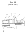
cable 4, a connectingdevice 8 is installed to fix thecable 4 to a bracket 7 outside the transmission and connect a transmission's shift lever (not shown) to saidcable 4. As illustrated in FIG. 2b, the connectingdevice 8 has a connectingpiece 9 to which the other end of the cable's 4cover 4b is inserted and fixed, acasing cap 10 that protects thewires 4a, enabling them to move freely, and fixing them to the bracket 7 outside the transmission, aprotection tube 11 that protects wires' 4a ends through thecasing cap 10, and a connectingtube 13 that fastens theprotection tube 11 to thecasing cap 10 with fastening devices such asrings 12. Bellows 14, illustrated in FIG. 3, are installed to the connectingdevice 8 to protect the ends of the cable. - Based on the connection mechanism between the shift lever and the transmission, the pivot lever pivots if a driver changes the shift lever position among P, R, N, D, etc. The pivoting pulls or restores the
wires 4a of thecable 4, and subsequently operates the transmission lever that is connected to the wires and changes speed. Meanwhile, in case of four-wheel drive vehicles, though not exclusively, a TOD (torque on demand) is installed to the end of the transmission, automatically allocating and conveying the operating force from the transmission to front wheels and rear wheels. - However, in a conventional way of connecting a shift lever and a transmission with a shift cable, the following problems are likely to occur. First, each end of the cable is connected to a bracket at the shift lever and a bracket at the transmission respectively. As a result, driving noises from the TOD are conveyed directly to the shift lever through the cable and ultimately to the inside of the vehicle. Second, vibrations that occur from the TOD or the transmission are conveyed to the shift lever through the cable. The vibrations are then conveyed to the driver through the shift lever.
- The present invention addresses the aforementioned problems. A purpose of the present invention is to provide a transmission gear shift cable for an automatic transmission vehicle that prevents noises from the transmission or the TOD from being transferred to the inside of the vehicle through the cable.
- Another purpose of the invention is to provide a transmission gearshift cable for an automatic transmission vehicle that prevents vibration from the transmission or the TOD from being transferred to the shift lever though the cable.
- The aforementioned purposes can be achieved by the present transmission gear shift cable for automatic transmission vehicle comprising: a cable body including a wire that is connected to the pivot lever of the shift lever at a end of the wire and to the actuating lever of the transmission at the other end, and a cover that encircles said wire so that said wire can move freely; a fixed member that is to fix said cable body to a mounting bracket to fix a shift lever to a vehicle body and has a fixed piece with a perforation hole to which a fastening device and a vibration insulation bushing are inserted; and a connecting device to fix said cable body to a fixed bracket outside the transmission including a connecting piece to which an end of the cable body is inserted and fixed, a casing cap that is fixed to an end of said connecting piece, a connecting tube that is fixed to said casing cap and a transmission's bracket, a connecting rod which is inserted into said connecting tube and said cable body's wire are inserted into, and an insulation member that is installed to prevent driving noises and vibration from the transmission from being transferred to a shift lever.
- The above and other advantages of embodiments of this invention will be apparent from the following more detailed description when taken in conjunction with the accompanying drawings.
-
- FIG. 1a is a partial side view that shows how a general shift lever and a gearshift cable are connected.
- FIG. 1b is an enlarged section of part b from the FIG. 1a.
- FIG. 2a is a side view that shows how a general transmission's mounting bracket and a shift cable are connected.
- FIG. 2b is an enlarged section of part b from the FIG. 2a.
- FIG. 3 is a side view that shows an overall structure of a general transmission gearshift cable.
- FIG. 4 a side view of an overall structure of the present transmission gear shift cable for automatic transmission vehicle.
- FIG. 5 is a perspective view of a bushing applied to the shift cable in the FIG. 4.
- FIG. 6 is an enlarged partial section of an applied bushing in the FIG. 5.
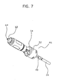
- FIG. 7 is an enlarged partial perspective view of the cable's connecting device in the FIG. 4.
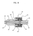
- FIG. 8 is an enlarged partial section of the FIG. 7.
- FIG. 9 is a graph that compares noise transfer of the present transmission gearshift cable and a traditional shift cable.
-
- In the following description, working examples will be explained in detail based on attached drawings.
- First, in FIG. 4, the present transmission gear shift cable for an automatic transmission vehicle comprises a wire 20 (that can be made of metal or other suitable material), and a
cable body 24 that consists of acover 22 encircling thewire 20 so that thewire 20 can move freely within a certain range. At one side of the cable body's 24wire 20, or more particularly, at the shift lever side, afixed end 26 is formed that is fixed to the actuating lever. At the other side of thewire 20, a connectingend 28 is formed that is fixed to the transmission's actuating lever (not shown). Further, at the cable's shift lever side is a fixedmember 30 that is fixed to or buttressed by a mounting bracket that attaches the cable to the mounting bracket. At the fixedmember 30, a supportingpiece 32 attaches the cable to the mounting bracket. In addition, the fixedmember 30 has a fixedpiece 36 that is integrally formed and fixed to a mounting fixed piece 34 (refer to FIG. 6) of the mounting bracket. Aperforation hole 36a is formed at the fixedpiece 36. - In particular, a
bushing 38 is inserted into theperforation hole 36a of the fixedpiece 36. As illustrated in FIG. 5 and FIG. 6 in detail, thebushing 38 comprises the combination of abody 40 and areinforcement member 44. Thebody 40 is made of elastic material such as rubber to stop the conveyance of vibration by preventing direct contacts between two metal parts, i.e. the fixedpiece 36 and the mounting bracket's mounting fixedpiece 34. The reinforcement member complements the body's stiffness and adjoinsbolts 42 designed to fix the mounting fixedpiece 34 to the fixedmember 30. - At the other side of the cable body, namely at the transmission side end, a connecting
device 46 is provided to fix the cable to the fixed bracket that is installed outside the transmission. As illustrated in FIG. 7 and FIG. 8 in detail, the connectingdevice 46 has a connectingpiece 48 to which some of the cable body's 24 section is inserted and fixed. The connectingpiece 48 is made of metal for stable support, and its end is preferably formed integrally with aflange 50 for a stable union. At the end of the connectingpiece 48 is acasing cap 52. Thecasing cap 52 is made of synthetic resin such as plastic and its shape is preferably a cylinder. - To the
casing cap 52 is added a connectingtube 54 that is actually fixed to the transmission's bracket. An end of the connecting tube is preferably inserted into thecasing cap 52 and integrally combined. In the central part of throughhole 56, protrudingborders 58 with a constant thickness are formed toward the center. Theborder 58 plays a role to prevent a connecting rod from being displaced. The connecting rod is described below. In particular, the throughhole 56 of the connectingtube 54 is preferably formed in a way that its diameter increases toward the other end, namely toward the transmission, so that the connecting rod can move freely and deflect easily within a certain degree. On the outside of the connecting tube's 54 other end, a fixinggroove 60 for the protection tube is created to protect the connecting rod from the exterior. - Connecting
rod 62 is inserted into the connecting tube's 54 throughhole 56. The connectingrod 62 has avertical guide hole 64 to which the cable body's 24wire 20 are inserted in a way that they can move back and forth freely. In particular, at the first gear part of the connecting rod is created a round inserting part. The inserting part is inserted into one side of the border in the connecting tube, namely in the right space in FIG. 8 in a way that it can rotate. - In particular, according to a characteristic of the present shift cable, an
insulation member 68 is attached to the connecting device to prevent noises from TOD operation from being transferred to the shift lever through the cable's wire. Theinsulation member 68 is preferably made of elastic material such as rubber or synthetic resin. In addition, theinsulation member 68 is placed between the connecting piece 48 (that the cable body's 24 wire pierces) and the connectingrod 62, and between thecasing cap 52 and the connectingtube 54 to prevent direct contacts of the parts. As a result, for instance, vibration from the wire or the connecting rod is completely absorbed by theinsulation member 68 and not transferred to the cable body. - Optionally, the
insulation member 68 can take various shapes. Preferably, it is formed so that it can completely encircle theflange 50 of the connectingpiece 48 and the connecting rod's 62 insertingpart 66. - The following describes how the transmission shift cable with the aforementioned structure works and operates. For example, while a vehicle is running, noises originate from the transmission, particularly the TOD in the back of the transmission. Also, vibration is conveyed to the connecting
rod 62 through the wire's 20 connectingend 28. However, theinsulation member 68 through theround inserting part 66 in the connecting rod's section absorbs vibration transferred to the connectingrod 62. Namely, the connecting rod's 62 insertingpart 66 is almost completely encircled by theinsulation member 68, which absorbs vibration. As a result, vibration is not transferred to the connectingpiece 48 because theinsulation member 68 intervenes to prevent the connecting rod's insertingpart 66 and the connectingpiece 48 from contacting with each other directly. Accordingly, driving noises and vibration are not transferred to the cable body through the connecting piece to the shift lever, and ultimately to the inside of the vehicle, which reduces noise levels inside the vehicle. - As illustrated in FIG. 9, driving noise from the present shift cable is less than driving noise from the conventional cable in the overall frequency area. According to the graph, in a 50 km-per-hour normal speed-driving test, noises decrease in the whole frequency area. In particular, in the 3KHz range, driving noises from TOD substantially decrease.
- Optionally, a rubber-made
bushing 38 can be inserted to the fixed piece's 34perforation hole 36a in the cable body's 24 shift lever side section and be fixed to the fixedmember 30 bybolts 42. As a result, even if driving noises and vibration are transferred to thecover 22 of thecable body 24,bushing 38, preventing the shift lever's vibration, absorbs them. Accordingly, noise can be reduced. - As a result, according to the present transmission gear shift, noise inside the vehicle is reduced because the connecting piece that the wire penetrates and the connecting rod do not adjoin each other directly but are separated by the insulation member made of elastic material in the casing cap and the connecting tube.
- While the invention has been described with regards to specific embodiments and specifications, those skilled in the art will recognize that changes can be made in form and detail without departing from the spirit and scope of the invention.
Claims (6)
- A transmission gearshift cable for an automatic transmission vehicle comprising:a cable body including a wire that is connected to the pivot lever of the shift lever at a end of the wire and to the actuating lever of the transmission at the other end, and a cover that encircles said wire so that said wire can move freely;a fixed member that is to fix said cable body to a mounting bracket to fix a shift lever to a vehicle body and has a fixed piece with a perforation hole to which a fastening device and a vibration insulation bushing are inserted; anda connecting device to fix said cable body to a fixed bracket outside the transmission including a connecting piece to which an end of the cable body is inserted and fixed, a casing cap that is fixed to an end of said connecting piece, a connecting tube that is fixed to said casing cap and a transmission's bracket, a connecting rod which is inserted into said connecting tube and said cable body's wire are inserted into, and an insulation member that is installed to prevent driving noises and vibration from the transmission from being transferred to a shift lever.
- The transmission gear shift cable for automatic transmission vehicle as claimed in claim 1, wherein said bushing contains integrally a rubber-made body to prevents said fixed member's fixed piece and the mounting bracket's supporting piece from contacting with each other directly and prevents vibration from being transferred, and a reinforcement member that complements said body's stiffness and adjoins bolts designed to fix said fixed piece to the mounting bracket.
- The transmission gear shift cable for automatic transmission vehicle as claimed in claim 1, wherein in the center of the through hoe of the connecting tube where said connecting rod is inserted protruding borders with a constant thickness are formed toward the center, and said through hole's diameters increase gradually from said borders to the transmission so that said connecting rod can move freely within a certain range.
- The transmission gear shift cable for automatic transmission vehicle as claimed in claim 3, wherein at one end of said connecting rod a round inserting part is formed integrally that is inserted into a shift lever side space formed by the borders in said connecting tube's through hole.
- The transmission gear shift cable for automatic transmission vehicle as claimed in claim 1, wherein said insulation member is placed between a connecting piece that said body's wire goes through and a connecting rod, and said casing cap and a connecting tube.
- The transmission gear shift cable for automatic transmission vehicle as claimed in claim 5, wherein said insulation member completely encircles an end of said connecting piece and said connecting rod's inserting part.
Applications Claiming Priority (2)
| Application Number | Priority Date | Filing Date | Title |
|---|---|---|---|
| KR2001071001 | 2001-11-15 | ||
| KR10-2001-0071001A KR100440004B1 (en) | 2001-11-15 | 2001-11-15 | transmission gear siftcable for automatic transmission vehicle |
Publications (2)
| Publication Number | Publication Date |
|---|---|
| EP1312838A2 true EP1312838A2 (en) | 2003-05-21 |
| EP1312838A3 EP1312838A3 (en) | 2005-03-23 |
Family
ID=19715995
Family Applications (1)
| Application Number | Title | Priority Date | Filing Date |
|---|---|---|---|
| EP02005950A Withdrawn EP1312838A3 (en) | 2001-11-15 | 2002-03-15 | Transmission gear shift cable for vehicle automatic transmission |
Country Status (4)
| Country | Link |
|---|---|
| US (1) | US20030089189A1 (en) |
| EP (1) | EP1312838A3 (en) |
| JP (1) | JP2003148609A (en) |
| KR (1) | KR100440004B1 (en) |
Cited By (2)
| Publication number | Priority date | Publication date | Assignee | Title |
|---|---|---|---|---|
| WO2009077815A1 (en) | 2007-12-19 | 2009-06-25 | Kongsberg Automotive Ab | Connecting device for transmission cable in vehicle |
| CN103821923A (en) * | 2012-11-15 | 2014-05-28 | 沃尔沃汽车公司 | Tuning structure for gear shift cables |
Families Citing this family (15)
| Publication number | Priority date | Publication date | Assignee | Title |
|---|---|---|---|---|
| KR100440004B1 (en) * | 2001-11-15 | 2004-07-14 | 기아자동차주식회사 | transmission gear siftcable for automatic transmission vehicle |
| KR100783531B1 (en) | 2006-11-21 | 2007-12-07 | 현대자동차주식회사 | Insulation Bush for Mounting |
| KR200448403Y1 (en) * | 2006-12-28 | 2010-04-09 | 주식회사 대동시스템 | Car cable support |
| US8671798B2 (en) * | 2008-06-18 | 2014-03-18 | Infac Corporation | Compression ring for an isolator in a motion transmitting remote control assembly |
| US8490512B2 (en) * | 2008-10-23 | 2013-07-23 | Dura Operating, Llc | Control cable assembly with dampening |
| KR101480571B1 (en) * | 2009-08-18 | 2015-01-08 | 현대자동차주식회사 | Noise reduction device of transmission cable |
| KR101113584B1 (en) * | 2009-09-07 | 2012-02-22 | 현대자동차주식회사 | Noise Reduction Apparatus for Shift Cable |
| CN104019215B (en) * | 2013-02-28 | 2016-04-27 | 江苏林海动力机械集团公司 | The comprehensive gearshift mechanism of all-terrain vehicle |
| KR101526698B1 (en) * | 2013-11-01 | 2015-06-05 | 현대자동차주식회사 | Shift cable for decreasing vibration |
| FR3038944B1 (en) * | 2015-07-15 | 2018-02-02 | Dura Automotive Systems Sas | FILTER CONNECTION TIP OF A SHEATH OR CABLE IN A SUPPORT |
| CN106050891A (en) * | 2016-07-21 | 2016-10-26 | 无锡市华锋车业部件有限公司 | Low-noise sleeve for automobile pull rope |
| CN106194979B (en) * | 2016-09-14 | 2018-06-08 | 湖南工业大学 | Vehicle automatic gear shifting inhaul cable assembly and quick assemble method |
| KR101947514B1 (en) | 2017-11-15 | 2019-02-13 | 주식회사 대동시스템 | Connecting assembly for parking state release |
| CN110748636B (en) * | 2019-11-21 | 2024-11-15 | 上海上汽马瑞利动力总成有限公司 | A noise reduction method and device for a hydraulic gear selector and shift actuator |
| CN114321141B (en) * | 2021-12-28 | 2023-02-10 | 深圳市康瑞普斯医疗器械有限公司 | A flexible shaft transmission structure |
Family Cites Families (13)
| Publication number | Priority date | Publication date | Assignee | Title |
|---|---|---|---|---|
| US3757612A (en) * | 1971-03-24 | 1973-09-11 | Gen Motors Corp | Transmission and controls |
| US5321993A (en) * | 1991-03-08 | 1994-06-21 | Chrysler Corporation | Transmission shift control apparatus |
| US5662004A (en) * | 1995-01-19 | 1997-09-02 | Grand Haven Stamped Products, Div. Of Jsj Corporation | Vehicle shift cable connection |
| KR19980013796A (en) * | 1996-08-02 | 1998-05-15 | 김영귀 | Bushing structure for trailing link of automobile suspension |
| CA2268326A1 (en) * | 1996-10-09 | 1998-04-16 | Peter C. Koenig | Expanding lock control cable end fitting |
| US5884531A (en) * | 1996-11-27 | 1999-03-23 | Dura Automotive Systems, Inc. | Low lash rotating conduit end fitting for a remote control cable assembly that isolates against vibration/noise transmission |
| ES2140298B1 (en) * | 1997-04-23 | 2001-03-01 | Fico Cables Sa | ADJUSTMENT DEVICE FOR CONTROL CABLES. |
| US5887485A (en) * | 1997-07-01 | 1999-03-30 | Prince Corporation | Vehicle console with built-in vehicle transmission shifter having cable tension adjustment mechanism and method |
| FR2776346B1 (en) * | 1998-03-17 | 2000-05-05 | Adwest Oci Sa | DEVICE FOR COUPLING AT LEAST ONE SHEATH ASSEMBLY OF CABLE AND GUIDE TUBE, TO A GEARBOX |
| IT1304991B1 (en) * | 1998-09-15 | 2001-04-05 | Sila Holding Ind S R L | FLEXIBLE CONTROL CABLE, PARTICULARLY FOR VEHICLE CHANGES. |
| JP2001254824A (en) * | 2000-03-08 | 2001-09-21 | Hino Motors Ltd | Cable-type operating device for vehicle transmission |
| US6520043B1 (en) * | 2000-06-30 | 2003-02-18 | Dura Global Technologies, Inc. | Transmission shifter with integrated cable adjustment mechanism |
| KR100440004B1 (en) * | 2001-11-15 | 2004-07-14 | 기아자동차주식회사 | transmission gear siftcable for automatic transmission vehicle |
-
2001
- 2001-11-15 KR KR10-2001-0071001A patent/KR100440004B1/en not_active Expired - Fee Related
-
2002
- 2002-03-12 JP JP2002066379A patent/JP2003148609A/en active Pending
- 2002-03-12 US US10/097,988 patent/US20030089189A1/en not_active Abandoned
- 2002-03-15 EP EP02005950A patent/EP1312838A3/en not_active Withdrawn
Non-Patent Citations (1)
| Title |
|---|
| None |
Cited By (5)
| Publication number | Priority date | Publication date | Assignee | Title |
|---|---|---|---|---|
| WO2009077815A1 (en) | 2007-12-19 | 2009-06-25 | Kongsberg Automotive Ab | Connecting device for transmission cable in vehicle |
| US9057400B2 (en) | 2007-12-19 | 2015-06-16 | Kongsberg Automotive Ab | Connecting device for transmission cable in vehicle |
| CN103821923A (en) * | 2012-11-15 | 2014-05-28 | 沃尔沃汽车公司 | Tuning structure for gear shift cables |
| US9863460B2 (en) | 2012-11-15 | 2018-01-09 | Volvo Car Corporation | Tuning structure for gear shift cables |
| CN103821923B (en) * | 2012-11-15 | 2018-05-25 | 沃尔沃汽车公司 | For the adjustment structure of gear shift cable |
Also Published As
| Publication number | Publication date |
|---|---|
| KR100440004B1 (en) | 2004-07-14 |
| EP1312838A3 (en) | 2005-03-23 |
| US20030089189A1 (en) | 2003-05-15 |
| JP2003148609A (en) | 2003-05-21 |
| KR20030039832A (en) | 2003-05-22 |
Similar Documents
| Publication | Publication Date | Title |
|---|---|---|
| US20030089189A1 (en) | Transmission gearshift cable for automatic transmission vehicle | |
| US6460822B1 (en) | Vehicle engine mount | |
| US8511201B2 (en) | Noise reduction apparatus for shift cable | |
| JPH04224329A (en) | Bracket elastically coupling car section, particularly coupling sub-frame with car body | |
| US20040207234A1 (en) | Front side-part structure of vehicle | |
| CN101992691A (en) | Apparatus for reducing noise of shift cable | |
| EP2733390A1 (en) | Dampening structure for gear shift cables | |
| US6988579B2 (en) | Power unit mount structure for vehicles | |
| EP2220386B9 (en) | Connecting device for transmission cable in vehicle | |
| JP3004584B2 (en) | Elastic stopper for anti-vibration device | |
| US6065559A (en) | Support structure for a vehicle powertrain | |
| JP3827306B2 (en) | Shift lever for vehicle | |
| KR102270353B1 (en) | High frequency noise reduction device of the shift cable for automobile | |
| KR100537002B1 (en) | Wind shield wiper linkage vibroisolating member for vehicle | |
| JP2000018326A (en) | Anti-vibration rubber structure | |
| JPS622335Y2 (en) | ||
| KR100410476B1 (en) | a cable mounting structure on shift lever assembly of an automatic transmission | |
| KR100475889B1 (en) | Reinforcing structure of engine mounying bracket for automobile | |
| KR100483119B1 (en) | A mounting structure of transmission for automobile | |
| KR100343584B1 (en) | mounting structure for oil reservoir tank of automotive vehicle | |
| KR0128072Y1 (en) | Mounting grommet for steering linkages | |
| JPH0117690Y2 (en) | ||
| JP3031161B2 (en) | Cable coupling device | |
| JPH0356417Y2 (en) | ||
| KR200170914Y1 (en) | Antivibration structure of cable for transmission of vehicles |
Legal Events
| Date | Code | Title | Description |
|---|---|---|---|
| PUAI | Public reference made under article 153(3) epc to a published international application that has entered the european phase |
Free format text: ORIGINAL CODE: 0009012 |
|
| 17P | Request for examination filed |
Effective date: 20020315 |
|
| AK | Designated contracting states |
Designated state(s): AT BE CH CY DE DK ES FI FR GB GR IE IT LI LU MC NL PT SE TR |
|
| AX | Request for extension of the european patent |
Extension state: AL LT LV MK RO SI |
|
| PUAL | Search report despatched |
Free format text: ORIGINAL CODE: 0009013 |
|
| AK | Designated contracting states |
Kind code of ref document: A3 Designated state(s): AT BE CH CY DE DK ES FI FR GB GR IE IT LI LU MC NL PT SE TR |
|
| AX | Request for extension of the european patent |
Extension state: AL LT LV MK RO SI |
|
| AKX | Designation fees paid |
Designated state(s): DE FR GB |
|
| STAA | Information on the status of an ep patent application or granted ep patent |
Free format text: STATUS: THE APPLICATION IS DEEMED TO BE WITHDRAWN |
|
| 18D | Application deemed to be withdrawn |
Effective date: 20050924 |