EP1312830A1 - Plastic movable guide for transmission device - Google Patents
Plastic movable guide for transmission device Download PDFInfo
- Publication number
- EP1312830A1 EP1312830A1 EP02024371A EP02024371A EP1312830A1 EP 1312830 A1 EP1312830 A1 EP 1312830A1 EP 02024371 A EP02024371 A EP 02024371A EP 02024371 A EP02024371 A EP 02024371A EP 1312830 A1 EP1312830 A1 EP 1312830A1
- Authority
- EP
- European Patent Office
- Prior art keywords
- plunger
- reinforcing plate
- guide
- receiving portion
- plate
- Prior art date
- Legal status (The legal status is an assumption and is not a legal conclusion. Google has not performed a legal analysis and makes no representation as to the accuracy of the status listed.)
- Granted
Links
- 239000004033 plastic Substances 0.000 title claims abstract description 32
- 229920003023 plastic Polymers 0.000 title claims abstract description 32
- 230000005540 biological transmission Effects 0.000 title claims abstract description 21
- 230000003014 reinforcing effect Effects 0.000 claims abstract description 114
- 229920003002 synthetic resin Polymers 0.000 claims description 9
- 239000000057 synthetic resin Substances 0.000 claims description 9
- 230000033001 locomotion Effects 0.000 claims description 5
- 230000006866 deterioration Effects 0.000 abstract description 6
- 239000000463 material Substances 0.000 description 5
- 229920005989 resin Polymers 0.000 description 5
- 239000011347 resin Substances 0.000 description 5
- 238000004519 manufacturing process Methods 0.000 description 4
- 229910052751 metal Inorganic materials 0.000 description 3
- 239000002184 metal Substances 0.000 description 3
- XEEYBQQBJWHFJM-UHFFFAOYSA-N Iron Chemical compound [Fe] XEEYBQQBJWHFJM-UHFFFAOYSA-N 0.000 description 2
- 239000004952 Polyamide Substances 0.000 description 2
- 238000005452 bending Methods 0.000 description 2
- 230000000694 effects Effects 0.000 description 2
- 229920006351 engineering plastic Polymers 0.000 description 2
- 230000006872 improvement Effects 0.000 description 2
- 150000002739 metals Chemical class 0.000 description 2
- 229920002647 polyamide Polymers 0.000 description 2
- 229910001018 Cast iron Inorganic materials 0.000 description 1
- 229920002430 Fibre-reinforced plastic Polymers 0.000 description 1
- FYYHWMGAXLPEAU-UHFFFAOYSA-N Magnesium Chemical compound [Mg] FYYHWMGAXLPEAU-UHFFFAOYSA-N 0.000 description 1
- RTAQQCXQSZGOHL-UHFFFAOYSA-N Titanium Chemical compound [Ti] RTAQQCXQSZGOHL-UHFFFAOYSA-N 0.000 description 1
- 230000001133 acceleration Effects 0.000 description 1
- 229910052782 aluminium Inorganic materials 0.000 description 1
- XAGFODPZIPBFFR-UHFFFAOYSA-N aluminium Chemical compound [Al] XAGFODPZIPBFFR-UHFFFAOYSA-N 0.000 description 1
- -1 cast iron Chemical class 0.000 description 1
- 238000002485 combustion reaction Methods 0.000 description 1
- 238000010276 construction Methods 0.000 description 1
- 230000008602 contraction Effects 0.000 description 1
- 238000005336 cracking Methods 0.000 description 1
- 238000004132 cross linking Methods 0.000 description 1
- 230000007423 decrease Effects 0.000 description 1
- 239000000835 fiber Substances 0.000 description 1
- 239000011151 fibre-reinforced plastic Substances 0.000 description 1
- 229910052733 gallium Inorganic materials 0.000 description 1
- 229910052742 iron Inorganic materials 0.000 description 1
- 230000001050 lubricating effect Effects 0.000 description 1
- 238000003754 machining Methods 0.000 description 1
- 229910052749 magnesium Inorganic materials 0.000 description 1
- 239000011777 magnesium Substances 0.000 description 1
- 230000007246 mechanism Effects 0.000 description 1
- 238000000034 method Methods 0.000 description 1
- 230000008569 process Effects 0.000 description 1
- 229910001220 stainless steel Inorganic materials 0.000 description 1
- 239000010935 stainless steel Substances 0.000 description 1
- 229910052719 titanium Inorganic materials 0.000 description 1
- 239000010936 titanium Substances 0.000 description 1
Images




Classifications
-
- F—MECHANICAL ENGINEERING; LIGHTING; HEATING; WEAPONS; BLASTING
- F16—ENGINEERING ELEMENTS AND UNITS; GENERAL MEASURES FOR PRODUCING AND MAINTAINING EFFECTIVE FUNCTIONING OF MACHINES OR INSTALLATIONS; THERMAL INSULATION IN GENERAL
- F16H—GEARING
- F16H7/00—Gearings for conveying rotary motion by endless flexible members
- F16H7/18—Means for guiding or supporting belts, ropes, or chains
-
- F—MECHANICAL ENGINEERING; LIGHTING; HEATING; WEAPONS; BLASTING
- F16—ENGINEERING ELEMENTS AND UNITS; GENERAL MEASURES FOR PRODUCING AND MAINTAINING EFFECTIVE FUNCTIONING OF MACHINES OR INSTALLATIONS; THERMAL INSULATION IN GENERAL
- F16H—GEARING
- F16H7/00—Gearings for conveying rotary motion by endless flexible members
- F16H7/08—Means for varying tension of belts, ropes or chains
- F16H2007/0863—Finally actuated members, e.g. constructional details thereof
- F16H2007/0872—Sliding members
Definitions
- This invention relates to a plastic movable guide for a flexible power transmission medium, such as chain which transmits power between sprockets, or a belt which transmits power between pulleys. It relates particularly to improvements in a mechanism in which the guide is pivoted on a mounting shaft and held in sliding engagement with the power transmission medium by the plunger of a tensioner lever.
- An engine generally includes a transmission device, which transmits power from the crankshaft to one or more camshafts by means of a chain, a belt or the like, as shown in FIG. 15.
- Similar power transmission devices are also used in other machines, especially where a driven shaft is to be rotated by a driving shaft which is parallel to, but spaced some distance from, the driven shaft.
- a movable guide Ga in sliding contact with a circulating power transmission medium, which in this case is an endless CH, cooperates with a tensioner T to maintain appropriate tension in the chain, and also prevents vibration in the plane of travel of the chain as well as transverse vibrations.
- the movable guide Ga is attached to a frame E of the engine on a supporting shaft P, which may be a mounting bolt, a pin or the like.
- a driving sprocket S1 which may be a crankshaft sprocket, operates driven sprockets S2, which may be camshaft sprockets, through the chain CH.
- a fixed guide Gb is also provided for limiting and guiding the travel of the circulating chain CH.
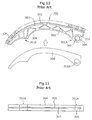
- FIG. 10 is a side elevational view a plastic movable guide 300, used as a tensioner lever in a chain transmission, which the present inventor previously described in Japanese Patent Application No. 2000-382798
- FIG. 11 is a bottom plan view of the plastic movable guide.
- a guide body 301 includes a shoe 302, with the surface of which a traveling chain CH is sliding contact.
- the guide body also includes a plate-receiving portion 303 extending along the back of the shoe 302 along the longitudinal direction of the guide.
- the shoe and plate-receiving portion are integrally molded as a unit from a synthetic resin.
- a mounting hole 305 for mounting the guide on the frame of an engine or other machine, is provided in the plate-receiving portion near one end of the guide.
- a through hole 308A is provided in the reinforcing plate 308 near one end thereof.
- the guide body 301 itself incorporates a shoe on which the chain slides, it is not necessary to provide a separate shoe member.
- the integrally molded construction reduces the number of parts required for the guide, and also reduces the number of required production steps.
- the reinforcing plate 308 increases the strength, toughness and bending rigidity of the guide in the pivoting direction.
- the relationships between the respective sizes and shapes of the guide body 301 and the reinforcing plate 308 are not particularly considered, and the mounting hole 305 was designed so that its diameter was the same as that of the through hole 308A.
- variations in accuracy in production, and the differences between coefficients of thermal expansion of materials either caused the reinforcing plate 308 to protrude slightly from the slot, or to retract into the slot by causing the reinforcing plate 308 to become slightly smaller than the guide body 301.
- Various phenomena occur as a result of these variations.
- the inventor has studied and analyzed the causes of noise and deterioration in plastic movable guides, and has found that the above-described problems are not generated in the same manner in all plastic movable guides.
- the level of metallic noise that occurs is higher than in the usual case, where the reinforcing plate is in flush relationship with the opening of the slot.
- the inventor also found that the other edge of the reinforcing plate 308 hit the bottom of the slot, i.e., the back surface of the shoe, as shown in FIG. 12(a), as the plate moved back and forth in the slot 307.
- the repeated engagement of the edge of the plate 308 with the back of the shoe resulted in cracks in the synthetic resin and caused deterioration of the shoe.
- the profile of the plunger-receiving portion 301B of the plastic movable guide 300 is a straight line.
- the contact angle between the front end of the plunger and the plunger-receiving portion changes in use as the plunger projects and the guide rotates about its pivot axis.
- the contact area between the front end of the plunger and the plunger-receiving portion decreases, and load is concentrated at one portion of the plunger-receiving portion.
- the inventor has found that the concentration of the load was a cause of accelerated wear in the plunger-receiving portion of the guide.
- the objects of this invention are to solve the above-mentioned problems encountered in the use of prior plastic movable guides, and to provide a plastic movable guide having superior quietness of operation, reduced production cost, and comparatively little wear of the reinforcing plate over a long period of time.
- a preferred plastic movable guide in accordance with the invention comprises a guide body including an elongated shoe having front and back sides facing in opposite directions, a surface on the front side of the shoe for sliding engagement with a traveling, flexible, power transmission medium, and a plate-receiving portion extending longitudinally along the back side of the shoe.
- the shoe and plate-receiving portion are integrally molded as a unit from a synthetic resin.
- the plate-receiving portion has a slot with an opening facing in a direction opposite to the direction in which said front side faces.
- the guide body has a mounting hole, adjacent to an end of the plate-receiving portion, for mounting the guide on a frame of a machine, and the reinforcing plate similarly has a through hole adjacent one of its ends.
- the mounting hole and the through hole are in register with each other so that a mounting shaft on which the guide is pivoted can extend through both holes.
- the guide body has a plunger-receiving portion at a location remote from the holes. The slot extends at least into the plunger-receiving portion.
- the reinforcing plate protrudes from the slot at the location of the plunger-receiving portion to expose at least a portion of an edge of the reinforcing plate, whereby a plunger of a tensioner may press directly against that portion of the edge of the reinforcing plate at that location.
- the protruding portion of the edge of the reinforcing plate has a curvature such that the area of contact between the reinforcing plate and an end surface of a plunger in the plunger is substantially constant irrespective of the contact angle between the reinforcing plate and the plunger.
- the curved portion of the edge of the reinforcing plate is preferably in the form of a convex or concave circular arc, depending on the shape of the end of the plunger with which it is in engagement.
- the transverse cross-sectional shape of the plunger-engaged edge of the reinforcing plate is preferably a substantially circular arc, a beveled rectangle, or a rectangle having rounded corners.
- the particular plastic material forming the guide body is not especially limited. However, since a surface suitable for sliding surface with a chain, a belt or the like is required so that the shoe portion of the guide functions properly, the material is preferably a so-called engineering plastic, such as a polyamide type resin, having superior wear resistance and lubricating properties. It is possible to utilize a fiber-reinforced resin solely, or to use a fiber-reinforced resin concurrently with another resin.
- the material of the reinforcing plate is likewise not especially limited, but, since the reinforcing plate must have the bending rigidity and strength required for the plastic movable guide, iron based metals such as cast iron, stainless steel and the like, nonferrous metals such as aluminum, magnesium, titanium and the like, engineering plastics such as polyamide type resin and the like, and fiber reinforced plastics, are preferably used.
- the reinforcing plate protrudes slightly from the slot, the reinforcing plate can remain in contact with the plunger during forward and backward movement of the plunger. Repeated contact between the reinforcing plate and the front end of the plunger at a high relative speed, due to back and forth motion of the reinforcing plate in the guide body, does not occur, and the generation of metallic noise is suppressed.
- the profile of the reinforcing plate is formed so that the reinforcing plate and end of the plunger maintain a substantially constant contact area irrespective of the angle between the plunger and the guide. Even if the angle varies as a result of elongation of the chain or other power transmission medium, a fixed contact area is maintained between the reinforcing plate and the front end surface of the plunger. Accordingly, no concentration of contact pressure occurs, and deterioration of the reinforcing plate due to wear is suppressed.
- the profile of the reinforcing plate at the location of the plunger-receiving portion can made be in the form of a convex or concave circular arc, without special machining processes, and with the profile in either of these forms, the contact area between the reinforcing plate and the end of the plunger can be maintained at a fixed value.
- the transverse cross-section of the plunger-contacting portion of the reinforcing plate is in the form of a substantially circular arc, or has beveled or rounded corners, even if vibration of the guide or the plunger of the tensioner causes the guide and plunger to become inclined relative to each other, concentration of load on a corner of the reinforcing plate is avoided, thereby reducing wear of the reinforcing plate and extending its useful life.
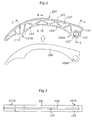
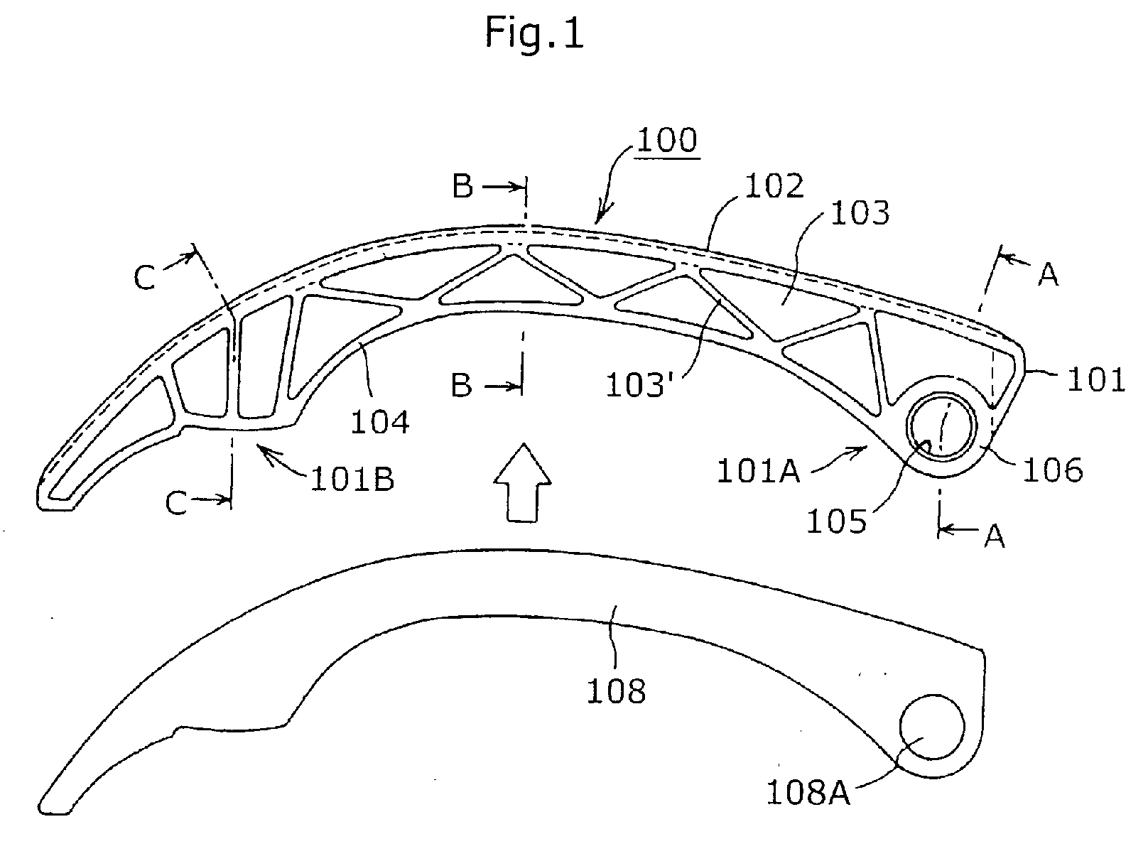
- FIG. 1 is an exploded side elevational view of a movable guide in accordance with a first embodiment of the invention
- FIG. 2 is a bottom plan view of the guide of FIG. 1;
- FIG. 3 is an exploded cross-sectional view taken on surface A-A in FIG. 1;
- FIG. 4 is a cross-sectional view taken on plane B-B in FIG. 1;
- FIG.5 is a cross-sectional view taken on surface C-C in FIG. 1, showing a plunger being brought into contact with a plunger-receiving portion on a pivoting front end of the guide;
- FIG. 6 is a side elevational view showing a reinforcing plate in accordance with a second embodiment of the invention in contact with the plunger of a tensioner;
- FIG. 7 is a side elevational view of the reinforcing plate shown in FIG. 6 showing the reinforcing plate and plunger engaged with each other at a different contact angle;
- FIG. 8(a) is a side elevational view showing another embodiment of the reinforcing plate in contact with a plunger
- FIG. 8(b) is a side elevational view showing the reinforcing plate of FIG. 8(a) in contact with the plunger at a different contact angle;
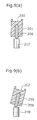
- FIG. 9(a) is a transverse cross-sectional view showing the plunger-receiving portion of a guide in accordance with another embodiment of the invention, in contact with a plunger of a tensioner;
- FIG. 9(b) shows the guide of FIG. 9(a) in a tilted relationship with the plunger
- FIG. 10 is an exploded elevational view of a conventional movable guide
- FIG. 11 is a bottom plan view of the conventional movable guide of FIG. 10;
- FIGs. 12(a) and 12(b) are transverse cross-sectional views of the plunger-receiving portion of the conventional movable guide, illustrating a problem encountered in the operation of the conventional guide;
- FIGs. 13(a) and 13(b) are side elevational views of the plunger-engaging portion of a reinforcing plate, illustrating another problem of the conventional movable guide.
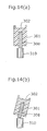
- FIGs. 14(a) and 14(b) are transverse cross-sectional views of the plunger-receiving portion of a movable guide, illustrating another problem, which is overcome by the embodiment illustrated in FIGs. 9(a) and 9(b); and
- FIG. 15 is an schematic view showing the timing transmission of an internal combustion engine, illustrating how a movable guide is used to guide a timing chain.
- the movable guide 100 shown in FIG. 1 is formed by incorporating a reinforcing plate 108 into a guide body 101 in a direction of the arrow.
- This guide body 101 is a plastic body integrally molded as a unit from synthetic resin.
- the guide body comprises a shoe 102, having on one side a sliding surface on which a traveling chain slides, and, on its opposite side, a plate-receiving portion 103, which is elongated along the longitudinal direction of the guide.
- the plate-receiving portion extends from the shoe in a direction opposite to the direction in which the sliding surface faces.
- the guide body 101 includes a flange 104 formed at an edge of the plate-receiving portion 103, and a boss 106 having a mounting hole 105 at an end 101A of the guide body 101 for pivotally mounting the guide on the frame of an engine, or other machine having a drive using a chain, belt, or similar flexible power transmission medium.
- the plate-receiving portion 103 has a truss-shaped array of reinforcing ribs 103', and a slot 107 in the flange 104, the slot being open in a direction opposite to the direction in which the sliding surface of the shoe faces, as can be seen from FIGS. 3 to 5.
- a reinforcing plate 108 having a mounting hole 108A for receiving a bolt or the like, is fitted into the slot 107.
- a plunger-receiving portion 101B is formed near the pivoting front end of the guide body 101.
- the reinforcing plate 108 protrudes slightly from the slot opening at this location, and plunger 110 of a tensioner presses against the protruding portion of the reinforcing plate. Because the reinforcing plate 108 protrudes slightly from the slot, when the plunger contacts the reinforcing plate, the reinforcing plate does not move back and forth in the guide body, and the forward and backward movement of the plunger can be transmitted reliably to the guide at the location of the plunger-receiving portion 101B. Referring to FIG.
- the ratio (h/w), of the height h of the protruded portion to the width w of the slot 107 be less than 1.
- the reinforcing plate 108 has a width w of 3mm, and a height h of 0.5 mm.
- the ratio h/w is 0.17.
- the shape of the plunger-receiving portion is not especially limited. However, to prevent dislodging of the front end of the plunger from the plunger-receiving portion 101B by transverse vibration of the lever, it is desirable to form protruded portions 104A at the edges of the flange 104, as shown in FIG. 5, to prevent transverse shifting of the lever.
- the reinforcing plate 108 protrudes from the slot opening only at the plunger-receiving portion 101B, the plate may protrude from the slot opening along the entire length of the guide.
- a plastic movable guide with a reinforcing plate 108 fitted into it is attached to the frame of an engine or other machine by a shoulder bolt 109, having a pivot portion 109A as shown in FIG. 3, or a mounting pin provided on the frame in such a manner that the mounting bolt or pin penetrated through the guide body 101 and the reinforcing plate 108.
- the guide body 101 and the reinforcing plate 108 have different coefficients of thermal expansion, they are secured together only at the location of their mounting holes, which are near one end of the guide.
- the reinforcing plate and the guide body are otherwise relatively movable in the longitudinal direction, and accordingly, no deformation of the guide body or breakage of its plate-receiving portion occur due to thermal expansion or contraction.
- a reinforcing plate 208 which is fitted into a plastic guide body (not shown), has a protruding portion the profile of which is in the form of a convex, circular arc.
- the protruding portion is brought into contact with the front end of the plunger 210 of a tensioner (not shown).
- FIG. 6 shows the normal contact between the reinforcing plate 208 and the plunger 210
- FIG. 7 shows the contact between the reinforcing plate 208 and the plunger 210 when plunger has extended from the tensioner as a result of elongation of the chain in which tension is maintained.
- the profile of the plunger-contacting part of the reinforcing plate 208 is a convex arc, the same effect can be achieved when the profile is a concave, circular arc, provided that the end of the plunger has a convex shape.
- the front end of the plunger 210 has a convex, spherical shape
- the profile of the plunger-contacting part of the reinforcing plate 208 is a concave circular arc, having a greater radius of curvature than that of the spherical end of the plunger.
- the reinforcing plate 208 protrudes slightly from a slot in a guide body 201 having a chain-contacting sliding surface 202.
- the plunger-contacting edge of the reinforcing plate 208 which contacts the end of plunger 210, is in the form of a substantially circular arc in transverse cross-section. Even if the guide and the plunger 210 are laterally relative to each other in the lateral direction, as depicted in FIG. 9(b), the front end of the plunger does not contact a corner of the plate. Instead, it contacts the rounded edge, and a fixed contact area is maintained.
- the plunger-contacting edge of plate 208 can have beveled corners, or rounded comers.
- the reinforcing plate protrudes slightly from the slot opening, the plate reliably remains in contact with the end of the plunger as the plunger moves back and forth.
- the reinforcing plate does not move relative to the guide body into and out of the slot, and accordingly metallic noise is suppressed, and the overall noise of the engine is reduced.
- the guide body and reinforcing plate are mounted on a bolt or mounting pin extending through holes adjacent one end of the guide, even if they have different coefficients of thermal expansion, they are free to expand and contract longitudinally relative to each other, and accordingly thermal deformation of the guide and breakage of the plate-receiving portion are avoided.
- the profile of the reinforcing plate is formed so that it contacts the end surface of the plunger over a fixed contact area irrespective of the contact angle between the plunger-receiving portion and the plunger, if the contact angle changes as the chain or other transmission medium elongates, the fixed contact area is maintained, concentration of contact pressure is avoided, and deterioration of the plunger-contacting edge of the reinforcing plate due to wear is reduced.
- the contact area between the reinforcing plate and the front end of the plunger can be maintained at a fixed value, but the profile is very simple and can be produced without special working.
- the transverse cross-section of the plunger-contacting edge of the reinforcing plate is a substantially circular arc, or has beveled or rounded corners, even if vibration causes the guide and plunger to be inclined relative to each other, concentration of load at a comer of the edge of the reinforcing plate is avoided, and wear of the reinforcing plate can be suppressed for a long period of time.
Landscapes
- Engineering & Computer Science (AREA)
- General Engineering & Computer Science (AREA)
- Mechanical Engineering (AREA)
- Devices For Conveying Motion By Means Of Endless Flexible Members (AREA)
Abstract
Description
- This invention relates to a plastic movable guide for a flexible power transmission medium, such as chain which transmits power between sprockets, or a belt which transmits power between pulleys. It relates particularly to improvements in a mechanism in which the guide is pivoted on a mounting shaft and held in sliding engagement with the power transmission medium by the plunger of a tensioner lever.
- An engine generally includes a transmission device, which transmits power from the crankshaft to one or more camshafts by means of a chain, a belt or the like, as shown in FIG. 15. Similar power transmission devices are also used in other machines, especially where a driven shaft is to be rotated by a driving shaft which is parallel to, but spaced some distance from, the driven shaft. In the transmission device of FIG. 15, a movable guide Ga, in sliding contact with a circulating power transmission medium, which in this case is an endless CH, cooperates with a tensioner T to maintain appropriate tension in the chain, and also prevents vibration in the plane of travel of the chain as well as transverse vibrations.
- The movable guide Ga is attached to a frame E of the engine on a supporting shaft P, which may be a mounting bolt, a pin or the like. In FIG. 15, a driving sprocket S1, which may be a crankshaft sprocket, operates driven sprockets S2, which may be camshaft sprockets, through the chain CH. A fixed guide Gb is also provided for limiting and guiding the travel of the circulating chain CH.
- FIG. 10 is a side elevational view a plastic
movable guide 300, used as a tensioner lever in a chain transmission, which the present inventor previously described in Japanese Patent Application No. 2000-382798, and FIG. 11 is a bottom plan view of the plastic movable guide. - In this plastic
movable guide 300, aguide body 301 includes ashoe 302, with the surface of which a traveling chain CH is sliding contact. The guide body also includes a plate-receivingportion 303 extending along the back of theshoe 302 along the longitudinal direction of the guide. The shoe and plate-receiving portion are integrally molded as a unit from a synthetic resin. Aplate 308, composed of a rigid material, typically metal, reinforces theguide body 301, fits into aslot 307 in the plate receiving portion. This slot extends along the longitudinal direction of the guide and has its opening facing in a direction opposite to the direction in which the chain-engaging surface of the shoe faces. Amounting hole 305, for mounting the guide on the frame of an engine or other machine, is provided in the plate-receiving portion near one end of the guide. A throughhole 308A is provided in the reinforcingplate 308 near one end thereof. These holes, 305 and 308A, are in register with each other when the reinforcing plate is inserted into theslot 307 in the plate-receiving portion, and both receive a supporting shaft P (FIG. 15). - Since the
guide body 301 itself incorporates a shoe on which the chain slides, it is not necessary to provide a separate shoe member. Thus, the integrally molded construction reduces the number of parts required for the guide, and also reduces the number of required production steps. The reinforcingplate 308 increases the strength, toughness and bending rigidity of the guide in the pivoting direction. - In the plastic
movable guide 300, the relationships between the respective sizes and shapes of theguide body 301 and thereinforcing plate 308 are not particularly considered, and themounting hole 305 was designed so that its diameter was the same as that of the throughhole 308A. However, variations in accuracy in production, and the differences between coefficients of thermal expansion of materials, either caused the reinforcingplate 308 to protrude slightly from the slot, or to retract into the slot by causing the reinforcingplate 308 to become slightly smaller than theguide body 301. Various phenomena occur as a result of these variations. - When the above-mentioned plastic movable guide was attached to the frame of an engine and used as a tensioner lever, a higher level of noise occurred compared the level of noise occurring where a movable guide composed entirely of plastic was used. Accordingly, an improvement in quietness is desired.
- There was also a danger that the integrally molded, synthetic resin guide body would become worn and deteriorate, finally reaching a stage at which it would fracture when struck by the plunger of the tensioner. In order to reduce the rate of wear and deterioration, it was believed necessary to incorporate fibers in the synthetic resin, or to subject the synthetic resin to a cross-linking process or the like, both of which measures resulted in increased production cost.
- The inventor has studied and analyzed the causes of noise and deterioration in plastic movable guides, and has found that the above-described problems are not generated in the same manner in all plastic movable guides. When the reinforcing plate is retracted into the plate-receiving portion of the guide body at the location of the plunger-receiving portion, as shown in FIG. 12(a), the reinforcing
plate 308 moves back and forth in theslot 307 of theguide body 301 every time theplunger 310 hits theguide body 301. As a result the end portion of the reinforcing plate is brought into contact with the front surface of the plunger as shown in FIG. 12(b) and the level of metallic noise that occurs is higher than in the usual case, where the reinforcing plate is in flush relationship with the opening of the slot. Further, the inventor also found that the other edge of thereinforcing plate 308 hit the bottom of the slot, i.e., the back surface of the shoe, as shown in FIG. 12(a), as the plate moved back and forth in theslot 307. The repeated engagement of the edge of theplate 308 with the back of the shoe resulted in cracks in the synthetic resin and caused deterioration of the shoe. - As shown in FIG. 10, the profile of the plunger-receiving
portion 301B of the plasticmovable guide 300 is a straight line. Thus, the contact angle between the front end of the plunger and the plunger-receiving portion changes in use as the plunger projects and the guide rotates about its pivot axis. As shown in FIGS. 13(a) and 13(b), the contact area between the front end of the plunger and the plunger-receiving portion decreases, and load is concentrated at one portion of the plunger-receiving portion. The inventor has found that the concentration of the load was a cause of accelerated wear in the plunger-receiving portion of the guide. Additionally it has become clear that, while using the plastic movable guide, vibration can cause the movable guide, or the plunger, to become inclined relative to the plane of rotation of the plunger about its pivot axis. When this inclination occurs, as shown in FIGs. 14(a) and 14(b), load is concentrated at a corner of the edge of the reinforcing plate, causing acceleration of wear of the reinforcing plate. - Accordingly, the objects of this invention are to solve the above-mentioned problems encountered in the use of prior plastic movable guides, and to provide a plastic movable guide having superior quietness of operation, reduced production cost, and comparatively little wear of the reinforcing plate over a long period of time.
- A preferred plastic movable guide in accordance with the invention comprises a guide body including an elongated shoe having front and back sides facing in opposite directions, a surface on the front side of the shoe for sliding engagement with a traveling, flexible, power transmission medium, and a plate-receiving portion extending longitudinally along the back side of the shoe. The shoe and plate-receiving portion are integrally molded as a unit from a synthetic resin. The plate-receiving portion has a slot with an opening facing in a direction opposite to the direction in which said front side faces. An elongated reinforcing plate, provided for reinforcing the guide body, fits into the slot. The guide body has a mounting hole, adjacent to an end of the plate-receiving portion, for mounting the guide on a frame of a machine, and the reinforcing plate similarly has a through hole adjacent one of its ends. The mounting hole and the through hole are in register with each other so that a mounting shaft on which the guide is pivoted can extend through both holes. The guide body has a plunger-receiving portion at a location remote from the holes. The slot extends at least into the plunger-receiving portion. The reinforcing plate protrudes from the slot at the location of the plunger-receiving portion to expose at least a portion of an edge of the reinforcing plate, whereby a plunger of a tensioner may press directly against that portion of the edge of the reinforcing plate at that location. The protruding portion of the edge of the reinforcing plate has a curvature such that the area of contact between the reinforcing plate and an end surface of a plunger in the plunger is substantially constant irrespective of the contact angle between the reinforcing plate and the plunger. The curved portion of the edge of the reinforcing plate is preferably in the form of a convex or concave circular arc, depending on the shape of the end of the plunger with which it is in engagement. The transverse cross-sectional shape of the plunger-engaged edge of the reinforcing plate is preferably a substantially circular arc, a beveled rectangle, or a rectangle having rounded corners.
- The particular plastic material forming the guide body is not especially limited. However, since a surface suitable for sliding surface with a chain, a belt or the like is required so that the shoe portion of the guide functions properly, the material is preferably a so-called engineering plastic, such as a polyamide type resin, having superior wear resistance and lubricating properties. It is possible to utilize a fiber-reinforced resin solely, or to use a fiber-reinforced resin concurrently with another resin. The material of the reinforcing plate is likewise not especially limited, but, since the reinforcing plate must have the bending rigidity and strength required for the plastic movable guide, iron based metals such as cast iron, stainless steel and the like, nonferrous metals such as aluminum, magnesium, titanium and the like, engineering plastics such as polyamide type resin and the like, and fiber reinforced plastics, are preferably used.
- The following unique effects are obtained with the plastic movable guide according to the invention.
- First, since the reinforcing plate protrudes slightly from the slot, the reinforcing plate can remain in contact with the plunger during forward and backward movement of the plunger. Repeated contact between the reinforcing plate and the front end of the plunger at a high relative speed, due to back and forth motion of the reinforcing plate in the guide body, does not occur, and the generation of metallic noise is suppressed.
- Second, since hitting of the back surface of the shoe, due to back and forth motion of the reinforcing plate in the guide body, does not occur, cracks and wear in the shoe are significantly reduced.
- Third, the profile of the reinforcing plate is formed so that the reinforcing plate and end of the plunger maintain a substantially constant contact area irrespective of the angle between the plunger and the guide. Even if the angle varies as a result of elongation of the chain or other power transmission medium, a fixed contact area is maintained between the reinforcing plate and the front end surface of the plunger. Accordingly, no concentration of contact pressure occurs, and deterioration of the reinforcing plate due to wear is suppressed.
- The profile of the reinforcing plate at the location of the plunger-receiving portion can made be in the form of a convex or concave circular arc, without special machining processes, and with the profile in either of these forms, the contact area between the reinforcing plate and the end of the plunger can be maintained at a fixed value.
- If the transverse cross-section of the plunger-contacting portion of the reinforcing plate is in the form of a substantially circular arc, or has beveled or rounded corners, even if vibration of the guide or the plunger of the tensioner causes the guide and plunger to become inclined relative to each other, concentration of load on a corner of the reinforcing plate is avoided, thereby reducing wear of the reinforcing plate and extending its useful life.
- FIG. 1 is an exploded side elevational view of a movable guide in accordance with a first embodiment of the invention;
- FIG. 2 is a bottom plan view of the guide of FIG. 1;
- FIG. 3 is an exploded cross-sectional view taken on surface A-A in FIG. 1;
- FIG. 4 is a cross-sectional view taken on plane B-B in FIG. 1;
- FIG.5 is a cross-sectional view taken on surface C-C in FIG. 1, showing a plunger being brought into contact with a plunger-receiving portion on a pivoting front end of the guide;
FIG. 6 is a side elevational view showing a reinforcing plate in accordance with a second embodiment of the invention in contact with the plunger of a tensioner; - FIG. 7 is a side elevational view of the reinforcing plate shown in FIG. 6 showing the reinforcing plate and plunger engaged with each other at a different contact angle;
- FIG. 8(a) is a side elevational view showing another embodiment of the reinforcing plate in contact with a plunger;
- FIG. 8(b) is a side elevational view showing the reinforcing plate of FIG. 8(a) in contact with the plunger at a different contact angle;
- FIG. 9(a) is a transverse cross-sectional view showing the plunger-receiving portion of a guide in accordance with another embodiment of the invention, in contact with a plunger of a tensioner;
- FIG. 9(b) shows the guide of FIG. 9(a) in a tilted relationship with the plunger;
- FIG. 10 is an exploded elevational view of a conventional movable guide;
- FIG. 11 is a bottom plan view of the conventional movable guide of FIG. 10;
- FIGs. 12(a) and 12(b) are transverse cross-sectional views of the plunger-receiving portion of the conventional movable guide, illustrating a problem encountered in the operation of the conventional guide;
- FIGs. 13(a) and 13(b) are side elevational views of the plunger-engaging portion of a reinforcing plate, illustrating another problem of the conventional movable guide.
- FIGs. 14(a) and 14(b) are transverse cross-sectional views of the plunger-receiving portion of a movable guide, illustrating another problem, which is overcome by the embodiment illustrated in FIGs. 9(a) and 9(b); and
- FIG. 15 is an schematic view showing the timing transmission of an internal combustion engine, illustrating how a movable guide is used to guide a timing chain.
- The
movable guide 100, shown in FIG. 1 is formed by incorporating a reinforcingplate 108 into aguide body 101 in a direction of the arrow. Thisguide body 101 is a plastic body integrally molded as a unit from synthetic resin. The guide body comprises ashoe 102, having on one side a sliding surface on which a traveling chain slides, and, on its opposite side, a plate-receivingportion 103, which is elongated along the longitudinal direction of the guide. The plate-receiving portion extends from the shoe in a direction opposite to the direction in which the sliding surface faces. Theguide body 101 includes aflange 104 formed at an edge of the plate-receivingportion 103, and aboss 106 having a mountinghole 105 at anend 101A of theguide body 101 for pivotally mounting the guide on the frame of an engine, or other machine having a drive using a chain, belt, or similar flexible power transmission medium. The plate-receivingportion 103 has a truss-shaped array of reinforcing ribs 103', and aslot 107 in theflange 104, the slot being open in a direction opposite to the direction in which the sliding surface of the shoe faces, as can be seen from FIGS. 3 to 5. To reinforce theguide body 101, a reinforcingplate 108, having a mountinghole 108A for receiving a bolt or the like, is fitted into theslot 107. - As shown in FIG. 5, a plunger-receiving
portion 101B is formed near the pivoting front end of theguide body 101. The reinforcingplate 108 protrudes slightly from the slot opening at this location, andplunger 110 of a tensioner presses against the protruding portion of the reinforcing plate. Because the reinforcingplate 108 protrudes slightly from the slot, when the plunger contacts the reinforcing plate, the reinforcing plate does not move back and forth in the guide body, and the forward and backward movement of the plunger can be transmitted reliably to the guide at the location of the plunger-receivingportion 101B. Referring to FIG. 5, although the extent to which the reinforcing plate protrudes from the slot is not critical, it is desirable that the ratio (h/w), of the height h of the protruded portion to the width w of theslot 107, be less than 1. In an example of a preferred embodiment, the reinforcingplate 108 has a width w of 3mm, and a height h of 0.5 mm. Thus, in this case, the ratio h/w is 0.17. - The shape of the plunger-receiving portion is not especially limited. However, to prevent dislodging of the front end of the plunger from the plunger-receiving
portion 101B by transverse vibration of the lever, it is desirable to form protrudedportions 104A at the edges of theflange 104, as shown in FIG. 5, to prevent transverse shifting of the lever. - Although in the embodiment shown in FIGs. 1-5, the reinforcing
plate 108 protrudes from the slot opening only at the plunger-receivingportion 101B, the plate may protrude from the slot opening along the entire length of the guide. - A plastic movable guide with a reinforcing
plate 108 fitted into it is attached to the frame of an engine or other machine by ashoulder bolt 109, having apivot portion 109A as shown in FIG. 3, or a mounting pin provided on the frame in such a manner that the mounting bolt or pin penetrated through theguide body 101 and the reinforcingplate 108. - Even if the
guide body 101 and the reinforcingplate 108 have different coefficients of thermal expansion, they are secured together only at the location of their mounting holes, which are near one end of the guide. The reinforcing plate and the guide body are otherwise relatively movable in the longitudinal direction, and accordingly, no deformation of the guide body or breakage of its plate-receiving portion occur due to thermal expansion or contraction. - In another embodiment of the invention illustrated in FIGS. 6 and 7, a reinforcing
plate 208, which is fitted into a plastic guide body (not shown), has a protruding portion the profile of which is in the form of a convex, circular arc. The protruding portion is brought into contact with the front end of theplunger 210 of a tensioner (not shown). FIG. 6 shows the normal contact between the reinforcingplate 208 and theplunger 210, and FIG. 7 shows the contact between the reinforcingplate 208 and theplunger 210 when plunger has extended from the tensioner as a result of elongation of the chain in which tension is maintained. When the plunger extends, the contact angle between the reinforcing plate and the plunger changes, but, as is apparent from FIGS. 6 and 7, by making the profile of the plunger-contacting part of the reinforcingplate 208 in the form of a convex circular arc, a fixed contact area is always maintained, and, even if the contact angle between the reinforcing plate and the plunger changes, no concentration of load occurs. As a result, wear of the reinforcing plate is suppressed. Although in the embodiment illustrated in FIGs. 6 and 7, the profile of the plunger-contacting part of the reinforcingplate 208 is a convex arc, the same effect can be achieved when the profile is a concave, circular arc, provided that the end of the plunger has a convex shape. As shown in FIGs. 8(a) and 8(b), the front end of theplunger 210 has a convex, spherical shape, while the profile of the plunger-contacting part of the reinforcingplate 208 is a concave circular arc, having a greater radius of curvature than that of the spherical end of the plunger. - In the embodiment illustrated in FIGs. 9(a) and 9(b), the reinforcing
plate 208 protrudes slightly from a slot in aguide body 201 having a chain-contacting slidingsurface 202. The plunger-contacting edge of the reinforcingplate 208, which contacts the end ofplunger 210, is in the form of a substantially circular arc in transverse cross-section. Even if the guide and theplunger 210 are laterally relative to each other in the lateral direction, as depicted in FIG. 9(b), the front end of the plunger does not contact a corner of the plate. Instead, it contacts the rounded edge, and a fixed contact area is maintained. In alternative embodiments not illustrated, the plunger-contacting edge ofplate 208 can have beveled corners, or rounded comers. - The benefits afforded by the invention may be summarized as follows. First, since the reinforcing plate protrudes slightly from the slot opening, the plate reliably remains in contact with the end of the plunger as the plunger moves back and forth. The reinforcing plate does not move relative to the guide body into and out of the slot, and accordingly metallic noise is suppressed, and the overall noise of the engine is reduced. Second, since the reinforcing plate does not move into and out of the slot, it does not hit the bottom of the slot, i.e. the back surface of the shoe, cracking and wear of the shoe are significantly reduced, and the service life of the guide is increased. Third, since the guide body and reinforcing plate are mounted on a bolt or mounting pin extending through holes adjacent one end of the guide, even if they have different coefficients of thermal expansion, they are free to expand and contract longitudinally relative to each other, and accordingly thermal deformation of the guide and breakage of the plate-receiving portion are avoided.
- Since the profile of the reinforcing plate is formed so that it contacts the end surface of the plunger over a fixed contact area irrespective of the contact angle between the plunger-receiving portion and the plunger, if the contact angle changes as the chain or other transmission medium elongates, the fixed contact area is maintained, concentration of contact pressure is avoided, and deterioration of the plunger-contacting edge of the reinforcing plate due to wear is reduced.
- If the profile of the plunger-engaging portion of the reinforcing plate is a convex or concave circular arc, the contact area between the reinforcing plate and the front end of the plunger can be maintained at a fixed value, but the profile is very simple and can be produced without special working.
- If the transverse cross-section of the plunger-contacting edge of the reinforcing plate is a substantially circular arc, or has beveled or rounded corners, even if vibration causes the guide and plunger to be inclined relative to each other, concentration of load at a comer of the edge of the reinforcing plate is avoided, and wear of the reinforcing plate can be suppressed for a long period of time.
Claims (8)
- Plastic movable guide for a transmission device comprising:characterized in that the guide body (101; 201) having a plunger-receiving portion (101B) at a location remote from the holes (105, 108A), the slot (107) extending at least into the plunger-receiving portion (101B) of the guide body (101; 201), and the reinforcing plate (108; 208) protruding from the slot (107) at the location of the plunger-receiving portion (101B) to expose at least a portion of an edge of the reinforcing plate (108; 208), whereby a plunger (110; 210) of a tensioner may press directly against the portion of the edge of the reinforcing plate (108; 208) at the location.a guide body (101; 201) including an elongated shoe (102; 202) having front and back sides facing in opposite directions, a surface on the front side of the shoe (102; 202) for sliding engagement with a traveling, flexible, power transmission medium, and a plate-receiving portion (103) extending longitudinally along the back side of the shoe (102; 202), the shoe (102; 202) and plate-receiving portion (103) being integrally molded as a unit from a synthetic resin, and the plate-receiving portion (103) having a slot (107) with an opening facing in a direction opposite to the direction in which the front side faces;an elongated reinforcing plate (108; 208) for reinforcing the guide body (101; 201), the reinforcing plate (108; 208) being fitted into the slot (107);the guide body (101; 201) having a mounting hole (105) adjacent to an end (101A) of the plate-receiving portion (103) for mounting the plastic movable guide (100) on a frame of a machine, and the reinforcing plate (108; 208) having a through hole (108A) adjacent an end of the reinforcing plate (108; 208), the mounting hole (105) and the through hole (108A) being in register with each other whereby a mounting shaft (109) on which the plastic movable guide (100) is pivoted can extend through both of the holes (105, 108A);
- Plastic movable guide for a transmission device according to claim 1, characterized in that the portion of an edge of the reinforcing plate ( 208) has a curvature such that the area of contact between the reinforcing plate (208) and an end surface of a plunger (210) in the tensioner is substantially constant irrespective of the contact angle between the reinforcing plate (208) and the plunger (210).
- Plastic movable guide for a transmission device according to claim 2, characterized in that the portion of an edge of the reinforcing plate (208) is in the form of a convex circular arc.
- Plastic movable guide for a transmission device according to claim 2 or 3, in which the portion of an edge of the reinforcing plate (208) is in the form of a concave circular arc.
- Plastic movable guide for a transmission device according to one of claims 1 to 4, characterized in that the portion of an edge of the reinforcing plate (108; 208) has a cross-sectional shape transverse to the direction of elongation of the guide body (101; 201) from the group consisting of a substantially circular arc, a beveled rectangle, or rectangle having rounded corners.
- Pivoting tensioner assembly comprising a mounting shaft (109), a plastic movable guide (100; 200) pivoted on the mounting shaft (109) and having a plunger-engaging portion (101B) remote from the mounting shaft (109), and a tensioner having a plunger (110; 210) with an end surface in engagement with the plunger-engaging portion (101B);
wherein the plastic movable guide (100; 200) comprises a guide body (101; 201) including an elongated shoe (102; 202) having front and back sides facing in opposite directions, a surface on the front side of the shoe (102; 202) for sliding engagement with a traveling, flexible, power transmission medium, and a plate-receiving portion (103) extending longitudinally along the back side of the shoe (102; 202), the shoe (102; 202) and plate-receiving portion (103) being integrally molded as a unit from a synthetic resin, and the plate-receivingportion (103) having a slot (107) with an opening facing in a direction opposite to the direction in which the front side faces, and an elongated reinforcing plate (108; 208) for reinforcing the guide body (101; 201), the reinforcing plate (108; 208) being fitted into the slot (107);
wherein the guide body (101; 201) has a mounting hole (105) adjacent to an end (101A) of the plate-receiving portion (103), and the reinforcing plate (108) has a through hole (108A) adjacent an end of the reinforcing plate (108; 208), the mounting hole (105) and the through hole (108A) being in register with each other;
wherein the mounting shaft (109) extends through both of the holes (105, 108A) and the guide (100; 200) is pivoted on the mounting shaft (109) for rotation in a plane of rotation to which the mounting shaft (109) is perpendicular;
wherein the plunger (110; 210) is restricted to movement in a direction parallel to the plane of rotation; and
wherein the guide body (101; 201) has a plunger-receiving portion (101B) at a location remote from the holes (105, 108A), the slot (107) extends at least into the plunger-receiving portion (101B) of the guide body (101; 201), and the reinforcing plate (108; 208) protrudes from the slot (107) at the location of the plunger-receiving portion (101B) to expose a portion of an edge of the reinforcing plate (108; 208) as a plunger-engaging surface, whereby the plunger (110; 210) of the tensioner presses directly against this plunger-engaging portion of the edge of the reinforcing plate (108; 208) at the location in a direction parallel to the plane of rotation;
characterized in that at least one of the end surface of the plunger (110; 210) and the plunger-engaging portion is curved in the plane of rotation, and the shape of the end surface of the plunger (110; 210) and the shape of the plunger-engaging portion are related so that, as the plunger (110; 210) moves along the direction parallel to the plane of rotation while in contact with the plunger (110; 210), and the guide (100; 200) rotates about the shaft in its plane of rotation, the plunger (110; 210) and the plunger-engaging portion of the reinforcing plate (108; 208) contact each other over a substantially constant area. - Pivoting tensioner assembly according to claim 6, characterized in that the cross-sectional shape, of the plunger-engaging portion in planes perpendicular to the plane of rotation is convex, whereby contact between the plunger (210) and the plunger-engaging portion of the reinforcing plate (208) along a sharp comer of the reinforcing plate (208) is avoided even if the plastic movable guide (200) is tilted relative to the plane of rotation.
- Pivoting tensioner assembly according to claim 6 or 7, characterized in that the profile of the plunger-contacting part of the reinforcing plate (208) is in the form of a convex circular arc, the front end of the plunger (210) has a convex, spherical shape, and the concave circular arc, has a greater radius of curvature than that of the spherical end of the plunger (210).
Applications Claiming Priority (2)
| Application Number | Priority Date | Filing Date | Title |
|---|---|---|---|
| JP2001349133 | 2001-11-14 | ||
| JP2001349133A JP3336337B1 (en) | 2001-11-14 | 2001-11-14 | Plastic movable guide for transmission |
Publications (2)
| Publication Number | Publication Date |
|---|---|
| EP1312830A1 true EP1312830A1 (en) | 2003-05-21 |
| EP1312830B1 EP1312830B1 (en) | 2005-01-05 |
Family
ID=19161847
Family Applications (1)
| Application Number | Title | Priority Date | Filing Date |
|---|---|---|---|
| EP02024371A Expired - Lifetime EP1312830B1 (en) | 2001-11-14 | 2002-11-02 | Plastic movable guide for transmission device |
Country Status (5)
| Country | Link |
|---|---|
| US (1) | US7056243B2 (en) |
| EP (1) | EP1312830B1 (en) |
| JP (1) | JP3336337B1 (en) |
| CN (1) | CN1272561C (en) |
| DE (1) | DE60202513T2 (en) |
Cited By (4)
| Publication number | Priority date | Publication date | Assignee | Title |
|---|---|---|---|---|
| EP1503109A3 (en) * | 2003-07-31 | 2006-05-31 | Tsubakimoto Chain Co. | Lever for a transmission device |
| EP1746306A1 (en) * | 2005-07-20 | 2007-01-24 | DSM IP Assets B.V. | Guide for transmission device |
| DE10301427B4 (en) * | 2002-01-23 | 2009-04-23 | Tsubakimoto Chain Co. | Mobile guidance for a transmission device |
| EP2395261A4 (en) * | 2009-02-03 | 2013-02-20 | Ntn Toyo Bearing Co Ltd | Chain guide and chain tensioner device |
Families Citing this family (13)
| Publication number | Priority date | Publication date | Assignee | Title |
|---|---|---|---|---|
| DE202006008573U1 (en) * | 2006-05-30 | 2007-10-11 | JOH. WINKLHOFER & SÖHNE GMBH & Co. KG | Clamping rail with channel device in pressure body |
| WO2010099074A2 (en) * | 2009-02-27 | 2010-09-02 | Borgwarner Inc. | Automotive timing chain system component and method thereof |
| CN103384784B (en) * | 2011-02-23 | 2016-11-16 | Ntn株式会社 | Chain guide and chain stretching device |
| US9562593B2 (en) * | 2011-06-13 | 2017-02-07 | Ntn Corporation | Chain guide and chain drive apparatus |
| JP5706261B2 (en) * | 2011-07-25 | 2015-04-22 | Ntn株式会社 | Chain transmission for camshaft drive |
| WO2013136956A1 (en) * | 2012-03-12 | 2013-09-19 | Ntn株式会社 | Chain guide and chain drive device |
| EP2857718B1 (en) * | 2012-05-24 | 2017-01-04 | NTN Corporation | Chain guide and chain transmission device |
| JP2015059577A (en) | 2013-09-17 | 2015-03-30 | Ntn株式会社 | Chain transmission device |
| DE102013224007A1 (en) * | 2013-11-25 | 2015-05-28 | Schaeffler Technologies AG & Co. KG | Clamping rail and traction mechanism drive with such clamping rail |
| JP6278673B2 (en) * | 2013-11-28 | 2018-02-14 | Ntn株式会社 | Chain guide and chain transmission |
| JP6205291B2 (en) * | 2014-02-17 | 2017-09-27 | Ntn株式会社 | Chain drive for camshaft drive |
| JP6324359B2 (en) * | 2015-10-21 | 2018-05-16 | 株式会社椿本チエイン | Chain guide |
| FR3067782B1 (en) | 2017-06-15 | 2019-07-12 | Peugeot Citroen Automobiles Sa | METHOD FOR ASSEMBLING ENGINE DISTRIBUTION CHAIN GUIDES AND SYSTEM FOR GUIDING A DISTRIBUTION CHAIN |
Citations (4)
| Publication number | Priority date | Publication date | Assignee | Title |
|---|---|---|---|---|
| DE19523912A1 (en) * | 1995-06-30 | 1997-03-27 | Bosch Gmbh Robert | Guide rail, in particular tensioning rail for a camshaft drive of an internal combustion engine |
| GB2351136A (en) * | 1999-06-15 | 2000-12-20 | Tsubakimoto Chain Co | Tensioner lever |
| US20020077204A1 (en) * | 2000-12-15 | 2002-06-20 | Atsushi Kumakura | Pivotally movable plastic guide for power transmission device |
| EP1241380A2 (en) * | 2001-03-12 | 2002-09-18 | Tsubakimoto Chain Co. | Pivot member for a transmission belt guide |
Family Cites Families (10)
| Publication number | Priority date | Publication date | Assignee | Title |
|---|---|---|---|---|
| DE3706136C1 (en) * | 1987-02-26 | 1988-09-15 | Porsche Ag | Process for manufacturing a chain tensioner |
| US4826468A (en) * | 1987-11-18 | 1989-05-02 | Klifa Fahrzeugteile Gmbh & Co. | Chain tensioner |
| JP2540896Y2 (en) * | 1991-04-11 | 1997-07-09 | 株式会社椿本チエイン | Chain and other tensioner devices |
| JPH089476Y2 (en) * | 1991-11-07 | 1996-03-21 | 株式会社椿本チエイン | Integrated structure of chain guide arm and shoe |
| JP3941977B2 (en) | 1997-05-12 | 2007-07-11 | 株式会社椿本チエイン | Chain travel guide device |
| JP3269011B2 (en) * | 1997-07-28 | 2002-03-25 | 株式会社椿本チエイン | Transmission chain running guide shoe |
| JP2000097300A (en) * | 1998-09-24 | 2000-04-04 | Borg Warner Automotive Kk | Chain tensioner arm and chain guide |
| GB2347174B (en) * | 1999-02-23 | 2002-10-30 | Rover Group | A flexible drive assembly |
| JP2001141005A (en) * | 1999-11-10 | 2001-05-25 | Tsubakimoto Chain Co | Shoe for tensioner device and chain guide |
| JP4163364B2 (en) | 2000-03-31 | 2008-10-08 | 本田技研工業株式会社 | Engine lead screw tensioner |
-
2001
- 2001-11-14 JP JP2001349133A patent/JP3336337B1/en not_active Expired - Lifetime
-
2002
- 2002-10-28 US US10/281,758 patent/US7056243B2/en not_active Expired - Lifetime
- 2002-11-02 DE DE60202513T patent/DE60202513T2/en not_active Expired - Lifetime
- 2002-11-02 EP EP02024371A patent/EP1312830B1/en not_active Expired - Lifetime
- 2002-11-14 CN CNB021506787A patent/CN1272561C/en not_active Expired - Lifetime
Patent Citations (4)
| Publication number | Priority date | Publication date | Assignee | Title |
|---|---|---|---|---|
| DE19523912A1 (en) * | 1995-06-30 | 1997-03-27 | Bosch Gmbh Robert | Guide rail, in particular tensioning rail for a camshaft drive of an internal combustion engine |
| GB2351136A (en) * | 1999-06-15 | 2000-12-20 | Tsubakimoto Chain Co | Tensioner lever |
| US20020077204A1 (en) * | 2000-12-15 | 2002-06-20 | Atsushi Kumakura | Pivotally movable plastic guide for power transmission device |
| EP1241380A2 (en) * | 2001-03-12 | 2002-09-18 | Tsubakimoto Chain Co. | Pivot member for a transmission belt guide |
Cited By (6)
| Publication number | Priority date | Publication date | Assignee | Title |
|---|---|---|---|---|
| DE10301427B4 (en) * | 2002-01-23 | 2009-04-23 | Tsubakimoto Chain Co. | Mobile guidance for a transmission device |
| EP1503109A3 (en) * | 2003-07-31 | 2006-05-31 | Tsubakimoto Chain Co. | Lever for a transmission device |
| EP1746306A1 (en) * | 2005-07-20 | 2007-01-24 | DSM IP Assets B.V. | Guide for transmission device |
| WO2007009587A1 (en) * | 2005-07-20 | 2007-01-25 | Dsm Ip Assets B.V. | Guide for transmission device |
| EP2395261A4 (en) * | 2009-02-03 | 2013-02-20 | Ntn Toyo Bearing Co Ltd | Chain guide and chain tensioner device |
| US9115787B2 (en) | 2009-02-03 | 2015-08-25 | Ntn Corporation | Chain guide and chain tensioner device |
Also Published As
| Publication number | Publication date |
|---|---|
| DE60202513T2 (en) | 2005-12-22 |
| US20030092521A1 (en) | 2003-05-15 |
| JP2003148567A (en) | 2003-05-21 |
| JP3336337B1 (en) | 2002-10-21 |
| CN1419063A (en) | 2003-05-21 |
| US7056243B2 (en) | 2006-06-06 |
| DE60202513D1 (en) | 2005-02-10 |
| EP1312830B1 (en) | 2005-01-05 |
| CN1272561C (en) | 2006-08-30 |
Similar Documents
| Publication | Publication Date | Title |
|---|---|---|
| EP1312830B1 (en) | Plastic movable guide for transmission device | |
| US6884192B2 (en) | Movable guide for transmission device | |
| EP1300608B1 (en) | Movable lever for transmission chain | |
| EP1306580B1 (en) | Plastic movable guide for transmission device | |
| EP1245864B1 (en) | Plastic guide for transmission device | |
| EP1300607A2 (en) | Sliding contact guide for transmission device | |
| EP1306581B1 (en) | Plastic movable guide for transmission device | |
| US20060199689A1 (en) | Sliding contact guide for transmission | |
| US8007385B2 (en) | Sliding contact guide for transmission device | |
| US20050026730A1 (en) | Lever for transmission device | |
| US6849013B2 (en) | Sliding contact guide for transmission device | |
| US7137916B2 (en) | Movable guide for transmission device | |
| US20030139238A1 (en) | Sliding contact guide for transmission device | |
| GB2385650A (en) | Reinforced tensioner guide having a pressing member pressing against the reinforcing plate | |
| US6843742B2 (en) | Sliding contact guide for transmitting medium | |
| US20050277506A1 (en) | Synthetic resin guide | |
| US6849014B2 (en) | Sliding contact guide for transmission device | |
| RU2610729C2 (en) | Chain guige | |
| CN114321298B (en) | Chain guide | |
| JP2002098203A (en) | Chain tensioner device | |
| GB2433572A (en) | Chain guide/blade having a strengthening core |
Legal Events
| Date | Code | Title | Description |
|---|---|---|---|
| PUAI | Public reference made under article 153(3) epc to a published international application that has entered the european phase |
Free format text: ORIGINAL CODE: 0009012 |
|
| AK | Designated contracting states |
Designated state(s): AT BE BG CH CY CZ DE DK EE ES FI FR GB GR IE IT LI LU MC NL PT SE SK TR |
|
| AX | Request for extension of the european patent |
Extension state: AL LT LV MK RO SI |
|
| RAP1 | Party data changed (applicant data changed or rights of an application transferred) |
Owner name: TSUBAKIMOTO CHAIN CO. |
|
| RIN1 | Information on inventor provided before grant (corrected) |
Inventor name: KONNO, MASAHIKO,C/O TSUBAKIMOTO CHAIN CO. |
|
| 17P | Request for examination filed |
Effective date: 20030704 |
|
| AKX | Designation fees paid |
Designated state(s): DE FR GB |
|
| GRAP | Despatch of communication of intention to grant a patent |
Free format text: ORIGINAL CODE: EPIDOSNIGR1 |
|
| GRAS | Grant fee paid |
Free format text: ORIGINAL CODE: EPIDOSNIGR3 |
|
| GRAA | (expected) grant |
Free format text: ORIGINAL CODE: 0009210 |
|
| AK | Designated contracting states |
Kind code of ref document: B1 Designated state(s): DE FR GB |
|
| REG | Reference to a national code |
Ref country code: GB Ref legal event code: FG4D |
|
| REG | Reference to a national code |
Ref country code: IE Ref legal event code: FG4D |
|
| REF | Corresponds to: |
Ref document number: 60202513 Country of ref document: DE Date of ref document: 20050210 Kind code of ref document: P |
|
| PLBE | No opposition filed within time limit |
Free format text: ORIGINAL CODE: 0009261 |
|
| STAA | Information on the status of an ep patent application or granted ep patent |
Free format text: STATUS: NO OPPOSITION FILED WITHIN TIME LIMIT |
|
| 26N | No opposition filed |
Effective date: 20051006 |
|
| ET | Fr: translation filed | ||
| REG | Reference to a national code |
Ref country code: GB Ref legal event code: FG4D |
|
| PGFP | Annual fee paid to national office [announced via postgrant information from national office to epo] |
Ref country code: FR Payment date: 20081112 Year of fee payment: 7 |
|
| PGFP | Annual fee paid to national office [announced via postgrant information from national office to epo] |
Ref country code: GB Payment date: 20091028 Year of fee payment: 8 |
|
| REG | Reference to a national code |
Ref country code: FR Ref legal event code: ST Effective date: 20100730 |
|
| PG25 | Lapsed in a contracting state [announced via postgrant information from national office to epo] |
Ref country code: FR Free format text: LAPSE BECAUSE OF NON-PAYMENT OF DUE FEES Effective date: 20091130 |
|
| GBPC | Gb: european patent ceased through non-payment of renewal fee |
Effective date: 20101102 |
|
| PG25 | Lapsed in a contracting state [announced via postgrant information from national office to epo] |
Ref country code: GB Free format text: LAPSE BECAUSE OF NON-PAYMENT OF DUE FEES Effective date: 20101102 |
|
| PGFP | Annual fee paid to national office [announced via postgrant information from national office to epo] |
Ref country code: DE Payment date: 20210929 Year of fee payment: 20 |
|
| REG | Reference to a national code |
Ref country code: DE Ref legal event code: R071 Ref document number: 60202513 Country of ref document: DE |