EP1312511A1 - A rotary holder for corrugated tube - Google Patents
A rotary holder for corrugated tube Download PDFInfo
- Publication number
- EP1312511A1 EP1312511A1 EP02025549A EP02025549A EP1312511A1 EP 1312511 A1 EP1312511 A1 EP 1312511A1 EP 02025549 A EP02025549 A EP 02025549A EP 02025549 A EP02025549 A EP 02025549A EP 1312511 A1 EP1312511 A1 EP 1312511A1
- Authority
- EP
- European Patent Office
- Prior art keywords
- tube
- corrugated tube
- rotary
- outer fixing
- corrugated
- Prior art date
- Legal status (The legal status is an assumption and is not a legal conclusion. Google has not performed a legal analysis and makes no representation as to the accuracy of the status listed.)
- Granted
Links
Images


Classifications
-
- B—PERFORMING OPERATIONS; TRANSPORTING
- B60—VEHICLES IN GENERAL
- B60R—VEHICLES, VEHICLE FITTINGS, OR VEHICLE PARTS, NOT OTHERWISE PROVIDED FOR
- B60R16/00—Electric or fluid circuits specially adapted for vehicles and not otherwise provided for; Arrangement of elements of electric or fluid circuits specially adapted for vehicles and not otherwise provided for
- B60R16/02—Electric or fluid circuits specially adapted for vehicles and not otherwise provided for; Arrangement of elements of electric or fluid circuits specially adapted for vehicles and not otherwise provided for electric constitutive elements
- B60R16/0207—Wire harnesses
- B60R16/0215—Protecting, fastening and routing means therefor
Definitions
- the present invention relates to a rotary holder for corrugated tube holding rotatably a corrugated tube in which a wire harness is received.
- a wire harness is wired up between a vehicle body and the sliding door, in order to supply electric power from the vehicle body to these automotive electric equipments and to exchange control signals between the automotive electric equipments and the vehicle body.
- Wiring up the wire harness at the site requires that such a structure as to correspond to opening and closing of the sliding door is employed.
- a rotary holder for corrugated tube has been conventionally used as a part for wiring up the wire harness in corresponding to the opening and closing of the sliding door.
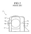
- a rotary holder for corrugated tube shown in Fig. 1 - 3 has been conventionally known.
- the rotary holder for corrugated tube 1 is composed of, as shown in Fig. 1 and 2, an outer fixing body 2 and an inner rotary body 3 received rotatablly in the interior of the outer fixing body 2.
- a corrugated tube 4 containing a wire harness W therein In the interior of the inner rotary body 3 held is a corrugated tube 4 containing a wire harness W therein.
- the outer fixing body 2 is assembled.
- an inner rotary chamber 7 At the center of the outer fixing body 2 formed is an inner rotary chamber 7.
- a harness support portion 8 At the one end portion of the outer fixing body 2 provided is a harness support portion 8 for receiving the wire harness W having appeared from the interior of the corrugated tube.
- a tube bend restraint portion 9 At the other end portion of the outer fixing body 2 provided is a tube bend restraint portion 9 for receiving the corrugated tube 4 and also for exposing the corrugated tube 4 to the exterior of the outer fixing body 2.
- the wire harness W appearing from the harness support portion 8 is wired up to a vehicle body (not shown in the figure), and the wire harness W within the corrugated tube 4 appearing from the tube bend restraint portion 9 is wired up to a sliding door (not shown in the figure).
- the inner rotary body 3 is composed of a pair of divided rotary member 10, 10 in the shape of a semi-cylinder having round arch surfaces 10a on the outer circumference of itself.
- the inner rotary body 3 is assembled.
- the inner rotary body 3 is received rotatably within the inner rotary chamber 7 of the outer fixing body 2, holding the corrugated tube 4 within the interior of the inner rotary body 3.
- the butt surface 5a of the base member 5 may displace from the butt surface 6a of the cover 6 due to failure of locking means 11 and 12 provided on the base member 5 and the cover 6, respectively. And it has been still liable that once the displacement between the butt surfaces 6a and 6a occur, a dislocation may be generated in an indentation portion formed at the site where the butt surface 5a of the base member 5 is engaged with the butt surface 6a of the cover 6, and the smooth sliding of the corrugated tube may further be prevented.
- the present invention aims to provide a rotary holder for corrugated tube wherein the corrugated tube can always move smoothly on an inner surface of a tube bend restraint portion of an outer fixing body.
- the present invention provides a rotary holder for corrugated tube, comprising: an outer fixing body formed by assembling a cover portion onto a base member, receiving rotatablly a corrugate tube; and a tube bend restraint portion provided at the end portion of the outer fixing body, for restraining a bend of the corrugated tube within a given range; wherein a tube slide area on which the corrugated tube moves sliding, in an inner surface of the tube bend restraint portion is formed only in either the base member or the cover portion.
- a rotary holder for corrugated tube 20 is composed of an outer fixing body 21 and an inner rotary body 22 received rotatablly in the interior of the outer fixing body 21.
- a corrugated tube 23 containing a wire harness W.
- the rotary holder for corrugated tube 20 is fixed to either a vehicle body (not shown in the figures) or a sliding door (not shown in the figures).
- the outer fixing body 21 is composed of a base member 24 made of synthetic resin and a cover 25 made of synthetic resin. As shown in Fig. 5 and Fig. 6, the outer fixing body 21 is formed by attaching the cover 25 onto the base member 24.
- the base member 24 has an inner rotary chamber (inner rotary portion) 26, a harness support portion 27, and a lower reception case portion 29 which forms a lower half of a tube bend restraint portion 28.
- the upper edge surface of the lower reception case portion 29 is a butt surface 29a.
- the cover 25 has an inner rotary chamber 26, a harness support portion 27, and a upper reception ease portion 30 which forms a upper half of a tube bend restraint portion 28.
- the lower edge surface of the upper reception case portion 30 is a butt surface 30a.
- the base member 24 is attached to the cover 25. Accordingly, at the center of the outer fixing body 21 formed is the inner rotary chamber 26, and at the one end portion of the outer fixing body 21 formed is the harness support portion 27, and at the other end portion of the outer fixing body 21 formed is the tube bend restraint portion 28.
- the harness support portion 27 is formed in the shape of a cylinder having a diameter a little bit larger than that of the wire harness W, and receives the wire harness W having appeared from the interior of the corrugated tube 23 within the interior of the harness support portion 27. And the wire harness appearing from the interior of the harness support portion 27 is wired up to the vehicle body.
- the corrugated tube 23 is received in the tube bend restraint portion 28. Further, the wire harness W contained in the corrugated tube 23 appearing from the tube bend restraint portion 28 is wired up to the sliding door.
- the tube bend restraint portion 28 is in the shape of an inverse U large enough in the direction of the Y-axis to correspond to the larger diameter (in the direction of Y-axis) of the corrugated tube 23. Additionally, the tube bend restraint portion 28 allows the corrugated tube 23 to rotate (movement) and also restrains bending of the corrugated tube 23 within the given range.
- the tube bend restraint portion 28 is formed from the upper reception case portion 30 and the lower reception case portion 29.
- the upper reception case portion 30 forms all of a top surface portion 28a, and almost all of right and left side surface portions 28b, 28c. Since the right and left side surface portions 28b, 28c of the upper reception case portion 30 are formed extending downward (in the direction of Y-axis) more than the conventional side surface portion, a tube slide area 50 where the corrugated tube 23 slides on the inner surface of the tube bend restraint portion 28 is formed only from the cover 25. That is to say, in the tube bend restraint portion 28, the butt surface 29a of the base member 24 is attached to the butt surface 30a of the cover 25 outside of the tube slide area 50.
- the inner surface of one side surface portion 28b of the upper reception case portion 30 is formed as a straight surface extending almost straight in the outward direction (in the direction of Z-axis) from the interior of the tube bend restraint portion 28.
- the inner surface of the other side surface portion 28c of the upper reception case portion 30 is formed as a taper surface gradually widening transversely (in the direction of X-axis) as it goes outward from the interior of the tube bend restraint portion 28. Still further, as shown in Fig.
- engagement channels 31, 31 respectively having a cross-section nearly in the shape of a V which channel their way from the center portion of the side surface portions 28b, 28c to the bottom openings.
- the lower reception case portion 29 provided are the lowest portions 28d, 28e forming the lowest edges of the right and left side surface portions 28b, 28c.
- a pair of engagement protrusions 32, 32 extruding upward are formed so as to extrude as the integral parts.
- the engagement protrusions 32, 32 of the lower reception case portion 29 are engaged with the engagement channels 31, 31 of the upper reception case portion 30 respectively.
- a tube restraint protrusion 33 disposed between the right and left side wall portion is provided at the deepest position from the inner rotary portion 26 of the lower reception case portion 29.
- lock arm reception portions (locking means) 35, 35 On both outer side surfaces of the lower reception case portion 29 provided are lock arm reception portions (locking means) 35, 35, and on both outer side surfaces of the upper reception case portion 30 provided are lock arm portions (locking means) 36, 36. Accordingly, the assembled state of the base member 24 and the cover 25 is tightly fixed through the lock arm portions 36, 36 being locked in the lock arm reception portions 35, 35 respectively.
- the inner rotary body 22 with a round arch surface 37a formed on its outer circumference is composed of a pair of divided rotary members 37, 37.
- a tube receptacle 38 is formed within the inner rotary body 22.
- a plurality of protrusions 38a are formed as the integral parts in the tube receptacle 38.
- each protrusion 38a held is each indentation 23a of the corrugated tube 23 in which contains the wire harness W. Since the corrugated tube 23 is a tube with an elliptic cross-section made of synthetic resin and has a bellows-like uneven surface on its outer circumference, it can wind and bend with ease.
- a yoke-like lock arm portion (locking means) 41 on one wall of right and left outer walls of the divided rotary members 37, 37 provided is a yoke-like lock arm portion (locking means) 41, and on the other wall provided is a hook-like lock arm reception portion (locking means) 42 in which the lock arm portion 41 is locked.
- a flange portion 37c in the shape of a round arch provide at one end of each divided rotary member 37 is received between a pair of flange portions 26a, 26a in the shape of a round arch formed protruding at one end of the inner rotary chamber 26. Further, through striking of a protrusion 37d protruding from the center of each divided rotary member 37 against a protrusion portion 26d protruding from the inner rotary chamber 26, the inner rotary body 22 rotates within the rotation angle of 180°.
- Each indentation 23a of the corrugated tube 23 with the elliptic cross-section is locked in a plurality of protrusion portions 38a protruding from the tube receptacle 38 of each divided rotary member 37.
- the corrugated tube 23 appears outside of the protrusion portion 38a provided at one end of each divided rotary member 37.
- a harness reception opening 38b being a U-channel is provided at the other end of each divided rotary member 37, and the wire harness W appearing from the corrugated tube received in the interior of the tube receptacle 38 appears outside of the outer fixing body 21 via the harness reception opening 38a and via the harness support portion 27 of the base member 24.
- the tube slide area 50 is formed only inside of the tube bend restraint portion 28a - 28c of the cover 25. Therefore, in sliding movement of the corrugated tube 23, there is no indentation portions (sharp edge portion) formed at the site where the butt surface 29a of the base member 24 is engaged with the butt surface 30a of the cover 25 in the tube slide area, which is the inner surface of the tube bend restraint portion 28. Consequently, it never occurs that the corrugated tube 23 may strike against an indentation portion formed at the site where the butt surfaces 29a and 30a are engaged, and the corrugated tube 23 can always move smoothly within the tube bend restraint portion 28 of the outer fixing body 21.
- the engagement channel 31 is formed as one-piece in the cover 25 forming the tube slide area 50 of the tube bend restraint portion 28, and since the engagement protrusion 32 to be engaged with the engagement channel 31 is formed as one-piece in the base member 24 not forming the tube slide area 50 of the tube bend restraint portion 28, the assembled state of the base member 24 and the cover 25 can be tightened.
- the cover 25 is chosen for a member where the tube slide area of the tube bend restraint portion 28 is to be formed, and the base member 24 is chosen for a member where the tube slide area of the tube bend restraint portion 28 is not to be formed.
- the base member 24cover can be chosen for the member where the tube slide area of the tube bend restraint portion 28 is to be formed, and the cover 25 can also be chosen for the member where the tube slide area of the tube bend restraint portion 28 is not to be formed.
- the rotary holder for corrugated tube is used at the site where the wire harness W on the vehicle body side is wired up to that on the sliding door side, sites where it is to be used are not confined thereto.
- the present rotary holder for corrugated tube 20 is provided with the tube bend restraint portion 28 only for one end portion, however the tube bend restraint portion 28 can be provided for each end portion on both sides.
- the corrugated tube 23 should not be confined to those of a flat type with an elliptic cross-section, but can be those of a cylinder type with a circular cross-section.
Abstract
Description
- The present invention relates to a rotary holder for corrugated tube holding rotatably a corrugated tube in which a wire harness is received.
- In the interior of a slide door used on a one-box car mounted are automotive electric equipments such as a power window motor, a door lock unit, a speaker. A wire harness is wired up between a vehicle body and the sliding door, in order to supply electric power from the vehicle body to these automotive electric equipments and to exchange control signals between the automotive electric equipments and the vehicle body. Wiring up the wire harness at the site requires that such a structure as to correspond to opening and closing of the sliding door is employed. A rotary holder for corrugated tube has been conventionally used as a part for wiring up the wire harness in corresponding to the opening and closing of the sliding door.
- A rotary holder for corrugated tube shown in Fig. 1 - 3 has been conventionally known. The rotary holder for
corrugated tube 1 is composed of, as shown in Fig. 1 and 2, anouter fixing body 2 and an inner rotary body 3 received rotatablly in the interior of theouter fixing body 2. In the interior of the inner rotary body 3 held is acorrugated tube 4 containing a wire harness W therein. - As shown in Fig. 1 and Fig. 2, by butting a
butt surface 5a of abase member 5 to abutt surface 6a of acover 6, theouter fixing body 2 is assembled. At the center of theouter fixing body 2 formed is an innerrotary chamber 7. At the one end portion of theouter fixing body 2 provided is aharness support portion 8 for receiving the wire harness W having appeared from the interior of the corrugated tube. Further, at the other end portion of theouter fixing body 2 provided is a tubebend restraint portion 9 for receiving thecorrugated tube 4 and also for exposing thecorrugated tube 4 to the exterior of theouter fixing body 2. And, the wire harness W appearing from theharness support portion 8 is wired up to a vehicle body (not shown in the figure), and the wire harness W within thecorrugated tube 4 appearing from the tubebend restraint portion 9 is wired up to a sliding door (not shown in the figure). - As shown in Fig. 1, the inner rotary body 3 is composed of a pair of divided
rotary member arch surfaces 10a on the outer circumference of itself. By butting abutt surface 10b of one dividedrotary member 10 to abutt surface 10b of the other dividedrotary member 10, the inner rotary body 3 is assembled. The inner rotary body 3 is received rotatably within the innerrotary chamber 7 of theouter fixing body 2, holding thecorrugated tube 4 within the interior of the inner rotary body 3. - When a wiring path of the
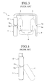
corrugated tube 4 is varied due to opening and closing motion of the sliding door under the above configuration, movement of thecorrugated tube 4 is restrained by the tubebend restraint portion 9 of theouter fixing body 2. Thereby, thecorrugated tube 4, as shown by the arrow in Fig. 3, moves rotating and bending within the interior of the tubebend restraint portion 9, sliding on the inner surface of the tubebend restraint portion 9. Through such movement of thecorrugated tube 4, the sliding door is opened and closed smoothly, and damage of thecorrugated tube 4 and the wire harness W in thecorrugated tube 4 is also reduced when opening and closing the sliding door. - However, in the conventional rotary holder for corrugated tube, since the
butt surfaces base member 5 and thecover 6 respectively composing theouter fixing body 2 are disposed on the inner surface of the tubebend restraint portion 9 of theouter fixing body 2 and also in the tube slide area on which thecorrugated tube 4 slides, it has been liable to occur that the corrugated tube may strike, during sliding movement of thecorrugated tube 4, against an indentation portion formed at the site where thebutt surfaces corrugated tube 4 may be prevented as shown in Fig. 4. - Further, it has been also liable to occur that the
butt surface 5a of thebase member 5 may displace from thebutt surface 6a of thecover 6 due to failure of locking means 11 and 12 provided on thebase member 5 and thecover 6, respectively. And it has been still liable that once the displacement between thebutt surfaces butt surface 5a of thebase member 5 is engaged with thebutt surface 6a of thecover 6, and the smooth sliding of the corrugated tube may further be prevented. - The present invention aims to provide a rotary holder for corrugated tube wherein the corrugated tube can always move smoothly on an inner surface of a tube bend restraint portion of an outer fixing body.
- In order to attain the above object, the present invention provides a rotary holder for corrugated tube, comprising: an outer fixing body formed by assembling a cover portion onto a base member, receiving rotatablly a corrugate tube; and a tube bend restraint portion provided at the end portion of the outer fixing body, for restraining a bend of the corrugated tube within a given range; wherein a tube slide area on which the corrugated tube moves sliding, in an inner surface of the tube bend restraint portion is formed only in either the base member or the cover portion.
-
- Fig. 1 is an exploded perspective view of an example of a conventional rotary holder for corrugated tube.
- Fig. 2 is a front view of the example of a conventional rotary holder for corrugated tube.
- Fig. 3 is an illustrative view showing a locus of movement of a corrugated tube within the interior of a tube bend restraint portion of the example of a conventional rotary holder for corrugated tube.
- Fig. 4 is an illustrative view showing a state where the example of
the conventional corrugated tube is sticking to an indentation portion formed
at the site where a
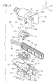
butt surface 5a of abase member 5 is engaged with abutt surface 6a of acover 6. - Fig. 5 is an exploded perspective view of an embodiment of the rotary holders for corrugated tube according to the present invention.
- Fig. 6 is an exploded cross-sectional view of an embodiment of the outer fixing bodies according to the present invention.
- Fig. 7 is an exploded front view of an embodiment of the inner rotary bodies according to the present invention.
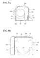
- Fig. 8A is a front view of an embodiment of the rotary holders for corrugated tube according to the present invention.
- Fig. 8B is an illustrative view showing a locus of movement of a corrugated tube in a tube slide area adjacent to the tube bend restraint portion of an embodiment of the rotary holders for corrugated tube according to the present invention.
-
- In the following, an embodiment of the present invention will be explained on the basis of the drawings.
- As shown in Fig. 5 Fig. 8A, a rotary holder for
corrugated tube 20 is composed of anouter fixing body 21 and an innerrotary body 22 received rotatablly in the interior of theouter fixing body 21. In the interior of the innerrotary body 22 held is acorrugated tube 23 containing a wire harness W. Here, the rotary holder forcorrugated tube 20 is fixed to either a vehicle body (not shown in the figures) or a sliding door (not shown in the figures). - The
outer fixing body 21 is composed of abase member 24 made of synthetic resin and acover 25 made of synthetic resin. As shown in Fig. 5 and Fig. 6, theouter fixing body 21 is formed by attaching thecover 25 onto thebase member 24. Thebase member 24 has an inner rotary chamber (inner rotary portion) 26, aharness support portion 27, and a lowerreception case portion 29 which forms a lower half of a tubebend restraint portion 28. The upper edge surface of the lowerreception case portion 29 is abutt surface 29a. Thecover 25 has aninner rotary chamber 26, aharness support portion 27, and a upperreception ease portion 30 which forms a upper half of a tubebend restraint portion 28. The lower edge surface of the upperreception case portion 30 is abutt surface 30a. By butting thebutt surface 30a of thecover 25 to thebutt surface 29a of thebase member 24, thebase member 24 is attached to thecover 25. Accordingly, at the center of theouter fixing body 21 formed is the innerrotary chamber 26, and at the one end portion of theouter fixing body 21 formed is theharness support portion 27, and at the other end portion of theouter fixing body 21 formed is the tubebend restraint portion 28. - In the interior of the inner
rotary chamber 26 received rotatably is the innerrotary body 22. Theharness support portion 27 is formed in the shape of a cylinder having a diameter a little bit larger than that of the wire harness W, and receives the wire harness W having appeared from the interior of thecorrugated tube 23 within the interior of theharness support portion 27. And the wire harness appearing from the interior of theharness support portion 27 is wired up to the vehicle body. - As shown in Fig. 5 and Fig. 8B, the
corrugated tube 23 is received in the tubebend restraint portion 28. Further, the wire harness W contained in thecorrugated tube 23 appearing from the tubebend restraint portion 28 is wired up to the sliding door. The tubebend restraint portion 28 is in the shape of an inverse U large enough in the direction of the Y-axis to correspond to the larger diameter (in the direction of Y-axis) of thecorrugated tube 23. Additionally, the tubebend restraint portion 28 allows thecorrugated tube 23 to rotate (movement) and also restrains bending of thecorrugated tube 23 within the given range. - Further, the tube
bend restraint portion 28 is formed from the upperreception case portion 30 and the lowerreception case portion 29. The upperreception case portion 30 forms all of atop surface portion 28a, and almost all of right and leftside surface portions side surface portions reception case portion 30 are formed extending downward (in the direction of Y-axis) more than the conventional side surface portion, atube slide area 50 where thecorrugated tube 23 slides on the inner surface of the tubebend restraint portion 28 is formed only from thecover 25. That is to say, in the tubebend restraint portion 28, thebutt surface 29a of thebase member 24 is attached to thebutt surface 30a of thecover 25 outside of thetube slide area 50. Concretely, the inner surface of oneside surface portion 28b of the upperreception case portion 30 is formed as a straight surface extending almost straight in the outward direction (in the direction of Z-axis) from the interior of the tubebend restraint portion 28. Further, the inner surface of the otherside surface portion 28c of the upperreception case portion 30 is formed as a taper surface gradually widening transversely (in the direction of X-axis) as it goes outward from the interior of the tubebend restraint portion 28. Still further, as shown in Fig. 8A, in the interiors of the right and leftside surface portions reception case portion 30, formed areengagement channels side surface portions side surface portion 28b forming a straight surface and the location of theside surface portion 28c forming a taper surface are reversed. - As shown in Fig. 5 and Fig. 8A, in the lower
reception case portion 29 provided are thelowest portions side surface portions lowest portions engagement protrusions base member 24 is attached to thecover 25, theengagement protrusions reception case portion 29 are engaged with theengagement channels reception case portion 30 respectively. Further, atube restraint protrusion 33 disposed between the right and left side wall portion is provided at the deepest position from theinner rotary portion 26 of the lowerreception case portion 29. - On both outer side surfaces of the lower
reception case portion 29 provided are lock arm reception portions (locking means) 35, 35, and on both outer side surfaces of the upperreception case portion 30 provided are lock arm portions (locking means) 36, 36. Accordingly, the assembled state of thebase member 24 and thecover 25 is tightly fixed through thelock arm portions arm reception portions - As shown in Fig. 5 and Fig. 7, the inner
rotary body 22 with a roundarch surface 37a formed on its outer circumference is composed of a pair of dividedrotary members rotary members rotary body 22. Under the condition where the dividedrotary members tube receptacle 38 is formed within the innerrotary body 22. A plurality ofprotrusions 38a are formed as the integral parts in thetube receptacle 38. By eachprotrusion 38a held is eachindentation 23a of thecorrugated tube 23 in which contains the wire harness W. Since thecorrugated tube 23 is a tube with an elliptic cross-section made of synthetic resin and has a bellows-like uneven surface on its outer circumference, it can wind and bend with ease. - Further, on one wall of right and left outer walls of the divided
rotary members lock arm portion 41 is locked. By locking thelock arm portion 41 in the lockarm reception portion 42, the assembled state of the dividedrotary members - As shown in Fig. 5, a
flange portion 37c in the shape of a round arch provide at one end of each dividedrotary member 37 is received between a pair offlange portions rotary chamber 26. Further, through striking of aprotrusion 37d protruding from the center of each dividedrotary member 37 against aprotrusion portion 26d protruding from the innerrotary chamber 26, the innerrotary body 22 rotates within the rotation angle of 180°. Eachindentation 23a of thecorrugated tube 23 with the elliptic cross-section is locked in a plurality ofprotrusion portions 38a protruding from thetube receptacle 38 of each dividedrotary member 37. And further, thecorrugated tube 23 appears outside of theprotrusion portion 38a provided at one end of each dividedrotary member 37. Moreover, aharness reception opening 38b being a U-channel is provided at the other end of each dividedrotary member 37, and the wire harness W appearing from the corrugated tube received in the interior of thetube receptacle 38 appears outside of the outer fixingbody 21 via theharness reception opening 38a and via theharness support portion 27 of thebase member 24. - When a wiring path of the
corrugated tube 23 is varied due to opening and closing motion of the sliding door under the above configuration, movement of thecorrugated tube 23 is restrained by the tubebend restraint portion 28 of the outer fixingbody 21. Thereby, thecorrugated tube 23, as shown by the arrow in Fig. 8B, moves rotating and bending within the interior of the tubebend restraint portion 28 sliding on the inner surface of the tubebend restraint portion 28. Concretely, thecorrugated tube 23 slides on the inner surface of theside surface portion bend restraint portion 28, and its large movement (in the direction of X-axis) is restrained by thetube restraint protrusion 33 provided between theside surface portion corrugated tube 23, the sliding door is opened and closed smoothly, and damage of thecorrugated tube 23 and the wire harness W received in the interior of thecorrugated tube 23 is also reduced during opening and closing the sliding door. - In the present embodiment, the
tube slide area 50 is formed only inside of the tubebend restraint portion 28a - 28c of thecover 25. Therefore, in sliding movement of thecorrugated tube 23, there is no indentation portions (sharp edge portion) formed at the site where thebutt surface 29a of thebase member 24 is engaged with thebutt surface 30a of thecover 25 in the tube slide area, which is the inner surface of the tubebend restraint portion 28. Consequently, it never occurs that thecorrugated tube 23 may strike against an indentation portion formed at the site where the butt surfaces 29a and 30a are engaged, and thecorrugated tube 23 can always move smoothly within the tubebend restraint portion 28 of the outer fixingbody 21. - In this embodiment, since the
engagement channel 31 is formed as one-piece in thecover 25 forming thetube slide area 50 of the tubebend restraint portion 28, and since theengagement protrusion 32 to be engaged with theengagement channel 31 is formed as one-piece in thebase member 24 not forming thetube slide area 50 of the tubebend restraint portion 28, the assembled state of thebase member 24 and thecover 25 can be tightened. - Additionally, in the present embodiment, the
cover 25 is chosen for a member where the tube slide area of the tubebend restraint portion 28 is to be formed, and thebase member 24 is chosen for a member where the tube slide area of the tubebend restraint portion 28 is not to be formed. However, the base member 24cover can be chosen for the member where the tube slide area of the tubebend restraint portion 28 is to be formed, and thecover 25 can also be chosen for the member where the tube slide area of the tubebend restraint portion 28 is not to be formed. Further, the rotary holder for corrugated tube is used at the site where the wire harness W on the vehicle body side is wired up to that on the sliding door side, sites where it is to be used are not confined thereto. Moreover, the present rotary holder forcorrugated tube 20 is provided with the tubebend restraint portion 28 only for one end portion, however the tubebend restraint portion 28 can be provided for each end portion on both sides. Still further, thecorrugated tube 23 should not be confined to those of a flat type with an elliptic cross-section, but can be those of a cylinder type with a circular cross-section.
Claims (3)
- A rotary holder for corrugated tube, comprising:an outer fixing body formed by assembling a cover portion onto a base member, receiving rotatablly a corrugate tube; anda tube bend restraint portion provided at the end portion of the outer fixing body, for restraining a bend of the corrugated tube within a given range; whereina tube slide area on which the corrugated tube moves sliding, in an inner surface of the tube bend restraint portion is formed only in either the base member or the cover portion.
- The rotary holder for corrugated tube described in claim 1, wherein an engagement channel is formed in the tube bend restraint portion of one member where the tube slide area is to be formed, and an engagement protrusion to be engaged with the engagement channel is formed in the other member where the tube slide area is not to be formed.
- The rotary holder for corrugated tube described in claim 2, wherein the member where the tube slide area is to be formed is the cover portion, and the member where the tube slide area is not to be formed is the base member.
Applications Claiming Priority (2)
| Application Number | Priority Date | Filing Date | Title |
|---|---|---|---|
| JP2001348942 | 2001-11-14 | ||
| JP2001348942A JP3741999B2 (en) | 2001-11-14 | 2001-11-14 | Corrugated tube rotation holder |
Publications (2)
| Publication Number | Publication Date |
|---|---|
| EP1312511A1 true EP1312511A1 (en) | 2003-05-21 |
| EP1312511B1 EP1312511B1 (en) | 2005-03-30 |
Family
ID=19161684
Family Applications (1)
| Application Number | Title | Priority Date | Filing Date |
|---|---|---|---|
| EP02025549A Expired - Fee Related EP1312511B1 (en) | 2001-11-14 | 2002-11-14 | A rotary holder for corrugated tube |
Country Status (4)
| Country | Link |
|---|---|
| US (1) | US6668865B2 (en) |
| EP (1) | EP1312511B1 (en) |
| JP (1) | JP3741999B2 (en) |
| DE (1) | DE60203467T2 (en) |
Cited By (5)
| Publication number | Priority date | Publication date | Assignee | Title |
|---|---|---|---|---|
| US6668865B2 (en) * | 2001-11-14 | 2003-12-30 | Yazaki Corporation | Rotary holder for corrugated tube |
| US6732764B2 (en) * | 2001-11-14 | 2004-05-11 | Yazaki Corporation | Rotatable holder |
| EP3109097A1 (en) * | 2015-06-26 | 2016-12-28 | Nexans | Device for holding a wiring harness |
| WO2018060377A1 (en) * | 2016-09-29 | 2018-04-05 | Phoenix Contact Gmbh & Co Kg | Cable holding device |
| US11377048B2 (en) * | 2020-03-03 | 2022-07-05 | Yazaki Corporation | Body side unit and wire harness wiring structure |
Families Citing this family (30)
| Publication number | Priority date | Publication date | Assignee | Title |
|---|---|---|---|---|
| US6968864B2 (en) * | 2001-11-14 | 2005-11-29 | Yazaki Corporation | Rotary holder for corrugated tube |
| US6913294B2 (en) * | 2002-11-14 | 2005-07-05 | Halla Climate Control Canada, Inc. | Coupling for coaxial connection of fluid conduits |
| JP2004194433A (en) * | 2002-12-11 | 2004-07-08 | Auto Network Gijutsu Kenkyusho:Kk | Cable tube material fixing joint |
| JP4261947B2 (en) * | 2003-03-14 | 2009-05-13 | 矢崎総業株式会社 | Harness fixture for sliding door feeding and feeding structure using it |
| US7073247B2 (en) * | 2003-04-30 | 2006-07-11 | General Electric Company | Method of brazing a liquid-cooled stator bar |
| JP4146327B2 (en) * | 2003-10-31 | 2008-09-10 | 矢崎総業株式会社 | Harness wiring structure using harness holder |
| US6854694B1 (en) * | 2003-11-03 | 2005-02-15 | Wayne Van Etten | Tube retainer |
| FR2863587B1 (en) * | 2003-12-11 | 2006-02-24 | Hurel Hispano | DEVICE FOR RETAINING A FIRE DETECTION SYSTEM |
| US7114687B2 (en) * | 2004-10-26 | 2006-10-03 | Osram Sylvania Inc. | Snap-on cable retainer |
| US7484534B2 (en) * | 2005-03-01 | 2009-02-03 | David Schmidt | Pipe casing method and apparatus |
| WO2007029060A1 (en) * | 2005-09-05 | 2007-03-15 | Project Control And Engineering Services (Proprietary) Limited | Duct assemblies for housing service cables, pipes and the like and components thereof |
| JP2008229986A (en) * | 2007-03-19 | 2008-10-02 | Toyoda Gosei Co Ltd | Bellows hollow body |
| US7692095B2 (en) * | 2007-08-21 | 2010-04-06 | Yazaki Corporation | Wire harness lead-out structure of protector |
| US8245527B2 (en) * | 2009-02-19 | 2012-08-21 | Ducharme David R | Ice making device |
| US8291551B2 (en) * | 2009-04-22 | 2012-10-23 | Deere & Company | Clamp assembly |
| JP5338635B2 (en) | 2009-11-20 | 2013-11-13 | アイシン精機株式会社 | Wiring holding structure |
| US20110226801A1 (en) * | 2010-03-19 | 2011-09-22 | Christy Smith-Heskel | Dispenser and associated methods |
| US20120008257A1 (en) * | 2010-07-06 | 2012-01-12 | 3M Innovative Properties Company | Cell tower wiring junction box |
| JP5353908B2 (en) * | 2011-01-21 | 2013-11-27 | 住友電装株式会社 | Wire harness protector |
| JP2013018322A (en) * | 2011-07-08 | 2013-01-31 | Sumitomo Wiring Syst Ltd | Wire harness routing structure part |
| JP2013096530A (en) * | 2011-11-02 | 2013-05-20 | Nifco Inc | Shaft body retainer |
| JP5927693B2 (en) * | 2012-02-01 | 2016-06-01 | 矢崎総業株式会社 | Protector and wire harness |
| US8607826B2 (en) * | 2012-03-30 | 2013-12-17 | Oceaneering International, Inc. | Interlocking bend limiter and method of assembly |
| US9484724B2 (en) | 2013-03-22 | 2016-11-01 | Michael Pecoraro | Cable protection device and system |
| JP6251520B2 (en) * | 2013-08-27 | 2017-12-20 | 矢崎総業株式会社 | Wire protection member |
| EP3093929A1 (en) * | 2015-05-15 | 2016-11-16 | ERICH JAEGER GmbH + Co. KG | Strain relief element for a cable and plug with strain relief element |
| JP5835601B1 (en) * | 2015-07-06 | 2015-12-24 | 住友電装株式会社 | Electric wire housing protector |
| JP6454312B2 (en) * | 2016-09-05 | 2019-01-16 | 矢崎総業株式会社 | Wire harness |
| JP6735313B2 (en) * | 2018-05-22 | 2020-08-05 | 矢崎総業株式会社 | Closure body holding structure and electric wire with connector |
| US11462897B2 (en) | 2020-10-22 | 2022-10-04 | Afl Telecommunications Llc | Cable mounting clamps |
Citations (4)
| Publication number | Priority date | Publication date | Assignee | Title |
|---|---|---|---|---|
| JPH118922A (en) * | 1997-06-17 | 1999-01-12 | Yazaki Corp | Protector |
| JP2000002364A (en) * | 1998-06-18 | 2000-01-07 | Furukawa Electric Co Ltd:The | Clamp |
| US6085795A (en) * | 1997-11-19 | 2000-07-11 | Yazaki Corporation | Corrugate tube fixing protector |
| JP2000197244A (en) * | 1998-12-24 | 2000-07-14 | Sumitomo Wiring Syst Ltd | Retaining member for bunch of wires |
Family Cites Families (6)
| Publication number | Priority date | Publication date | Assignee | Title |
|---|---|---|---|---|
| US3711633A (en) * | 1971-12-02 | 1973-01-16 | Gen Motors Corp | Fitting means for axially slit corrugated conduits |
| US4470622A (en) * | 1978-02-06 | 1984-09-11 | Thyssen-Bornemisza Inc. | Flexible conduit system |
| US4478278A (en) * | 1981-11-27 | 1984-10-23 | Texaco Canada Resources Ltd. | Spacer for deep wells |
| JP4092086B2 (en) * | 2000-06-30 | 2008-05-28 | 矢崎総業株式会社 | Corrugated tube fixture |
| JP3741999B2 (en) * | 2001-11-14 | 2006-02-01 | 矢崎総業株式会社 | Corrugated tube rotation holder |
| JP3741998B2 (en) * | 2001-11-14 | 2006-02-01 | 矢崎総業株式会社 | Corrugated tube rotation holder |
-
2001
- 2001-11-14 JP JP2001348942A patent/JP3741999B2/en not_active Expired - Lifetime
-
2002
- 2002-11-13 US US10/292,445 patent/US6668865B2/en not_active Expired - Lifetime
- 2002-11-14 EP EP02025549A patent/EP1312511B1/en not_active Expired - Fee Related
- 2002-11-14 DE DE60203467T patent/DE60203467T2/en not_active Expired - Lifetime
Patent Citations (4)
| Publication number | Priority date | Publication date | Assignee | Title |
|---|---|---|---|---|
| JPH118922A (en) * | 1997-06-17 | 1999-01-12 | Yazaki Corp | Protector |
| US6085795A (en) * | 1997-11-19 | 2000-07-11 | Yazaki Corporation | Corrugate tube fixing protector |
| JP2000002364A (en) * | 1998-06-18 | 2000-01-07 | Furukawa Electric Co Ltd:The | Clamp |
| JP2000197244A (en) * | 1998-12-24 | 2000-07-14 | Sumitomo Wiring Syst Ltd | Retaining member for bunch of wires |
Non-Patent Citations (3)
| Title |
|---|
| PATENT ABSTRACTS OF JAPAN vol. 1999, no. 04 30 April 1999 (1999-04-30) * |
| PATENT ABSTRACTS OF JAPAN vol. 2000, no. 04 31 August 2000 (2000-08-31) * |
| PATENT ABSTRACTS OF JAPAN vol. 2000, no. 10 17 November 2000 (2000-11-17) * |
Cited By (7)
| Publication number | Priority date | Publication date | Assignee | Title |
|---|---|---|---|---|
| US6668865B2 (en) * | 2001-11-14 | 2003-12-30 | Yazaki Corporation | Rotary holder for corrugated tube |
| US6732764B2 (en) * | 2001-11-14 | 2004-05-11 | Yazaki Corporation | Rotatable holder |
| EP3109097A1 (en) * | 2015-06-26 | 2016-12-28 | Nexans | Device for holding a wiring harness |
| WO2018060377A1 (en) * | 2016-09-29 | 2018-04-05 | Phoenix Contact Gmbh & Co Kg | Cable holding device |
| LU93242B1 (en) * | 2016-09-29 | 2018-04-11 | Phoenix Contact Gmbh & Co Kg Intellectual Property Licenses & Standards | Cable holder |
| CN109792138A (en) * | 2016-09-29 | 2019-05-21 | 菲尼克斯电气公司 | Cable holding meanss |
| US11377048B2 (en) * | 2020-03-03 | 2022-07-05 | Yazaki Corporation | Body side unit and wire harness wiring structure |
Also Published As
| Publication number | Publication date |
|---|---|
| DE60203467T2 (en) | 2006-02-16 |
| US20030116215A1 (en) | 2003-06-26 |
| US6668865B2 (en) | 2003-12-30 |
| DE60203467D1 (en) | 2005-05-04 |
| EP1312511B1 (en) | 2005-03-30 |
| JP2003153417A (en) | 2003-05-23 |
| JP3741999B2 (en) | 2006-02-01 |
Similar Documents
| Publication | Publication Date | Title |
|---|---|---|
| EP1312511B1 (en) | A rotary holder for corrugated tube | |
| US6787702B2 (en) | Harness-applied armoring member and harness-arranging structure using the same | |
| US7987554B2 (en) | Hinge structure for vehicle open/close body | |
| US6717055B2 (en) | Harness fixing device | |
| US7645938B2 (en) | Wiring harness fastening device for electric supply line of sliding door and electric supply system utilizing the same | |
| JP5012063B2 (en) | Wiring harness wiring structure for automobile | |
| EP2711760B1 (en) | Channel for slide-on-rod visors | |
| US7659480B2 (en) | Vehicle grommet | |
| CA2243385C (en) | Improved ball socket connector | |
| EP3766742B1 (en) | Slide door harness | |
| US8091949B2 (en) | Arrangement structure of door wire harness | |
| US20070084130A1 (en) | Channel Assembly for a Vehicle Window | |
| JP2009179201A (en) | Hinge structure of vehicular opening/closing body | |
| JP2006042566A (en) | Feeding device | |
| JP3879476B2 (en) | Grommet | |
| US20070209284A1 (en) | Electrical feeding unit and cable holder | |
| US11358446B2 (en) | Slide door structure | |
| JP2022038050A (en) | Height adjustment device | |
| JP3908010B2 (en) | Clamp lock structure | |
| WO2023176237A1 (en) | Electric wire guide structure and power supply device | |
| KR20180022370A (en) | Mounting structure of retractable outside door handle assembly for vehicle | |
| JPH0357066Y2 (en) | ||
| JPS6128340Y2 (en) | ||
| JP2002218631A (en) | Clamp for wire harness | |
| KR20230061795A (en) | Cargo screen of vehicle |
Legal Events
| Date | Code | Title | Description |
|---|---|---|---|
| PUAI | Public reference made under article 153(3) epc to a published international application that has entered the european phase |
Free format text: ORIGINAL CODE: 0009012 |
|
| 17P | Request for examination filed |
Effective date: 20021114 |
|
| AK | Designated contracting states |
Designated state(s): AT BE BG CH CY CZ DE DK EE ES FI FR GB GR IE IT LI LU MC NL PT SE SK TR |
|
| AX | Request for extension of the european patent |
Extension state: AL LT LV MK RO SI |
|
| AKX | Designation fees paid |
Designated state(s): DE FR GB IT |
|
| 17Q | First examination report despatched |
Effective date: 20040621 |
|
| GRAP | Despatch of communication of intention to grant a patent |
Free format text: ORIGINAL CODE: EPIDOSNIGR1 |
|
| GRAS | Grant fee paid |
Free format text: ORIGINAL CODE: EPIDOSNIGR3 |
|
| GRAA | (expected) grant |
Free format text: ORIGINAL CODE: 0009210 |
|
| AK | Designated contracting states |
Kind code of ref document: B1 Designated state(s): DE FR GB IT |
|
| REG | Reference to a national code |
Ref country code: GB Ref legal event code: FG4D |
|
| REF | Corresponds to: |
Ref document number: 60203467 Country of ref document: DE Date of ref document: 20050504 Kind code of ref document: P |
|
| REG | Reference to a national code |
Ref country code: IE Ref legal event code: FG4D |
|
| ET | Fr: translation filed | ||
| PLBE | No opposition filed within time limit |
Free format text: ORIGINAL CODE: 0009261 |
|
| STAA | Information on the status of an ep patent application or granted ep patent |
Free format text: STATUS: NO OPPOSITION FILED WITHIN TIME LIMIT |
|
| 26N | No opposition filed |
Effective date: 20060102 |
|
| REG | Reference to a national code |
Ref country code: FR Ref legal event code: PLFP Year of fee payment: 14 |
|
| PGFP | Annual fee paid to national office [announced via postgrant information from national office to epo] |
Ref country code: IT Payment date: 20151124 Year of fee payment: 14 Ref country code: GB Payment date: 20151111 Year of fee payment: 14 |
|
| REG | Reference to a national code |
Ref country code: FR Ref legal event code: PLFP Year of fee payment: 15 |
|
| GBPC | Gb: european patent ceased through non-payment of renewal fee |
Effective date: 20161114 |
|
| REG | Reference to a national code |
Ref country code: FR Ref legal event code: PLFP Year of fee payment: 16 |
|
| PG25 | Lapsed in a contracting state [announced via postgrant information from national office to epo] |
Ref country code: IT Free format text: LAPSE BECAUSE OF NON-PAYMENT OF DUE FEES Effective date: 20161114 |
|
| PG25 | Lapsed in a contracting state [announced via postgrant information from national office to epo] |
Ref country code: GB Free format text: LAPSE BECAUSE OF NON-PAYMENT OF DUE FEES Effective date: 20161114 |
|
| REG | Reference to a national code |
Ref country code: FR Ref legal event code: PLFP Year of fee payment: 17 |
|
| PGFP | Annual fee paid to national office [announced via postgrant information from national office to epo] |
Ref country code: DE Payment date: 20191029 Year of fee payment: 18 |
|
| PGFP | Annual fee paid to national office [announced via postgrant information from national office to epo] |
Ref country code: FR Payment date: 20191014 Year of fee payment: 18 |
|
| REG | Reference to a national code |
Ref country code: DE Ref legal event code: R119 Ref document number: 60203467 Country of ref document: DE |
|
| PG25 | Lapsed in a contracting state [announced via postgrant information from national office to epo] |
Ref country code: FR Free format text: LAPSE BECAUSE OF NON-PAYMENT OF DUE FEES Effective date: 20201130 |
|
| PG25 | Lapsed in a contracting state [announced via postgrant information from national office to epo] |
Ref country code: DE Free format text: LAPSE BECAUSE OF NON-PAYMENT OF DUE FEES Effective date: 20210601 |