EP1312455A2 - Injection mold and method for manufacturing injection molded articles - Google Patents
Injection mold and method for manufacturing injection molded articles Download PDFInfo
- Publication number
- EP1312455A2 EP1312455A2 EP02257939A EP02257939A EP1312455A2 EP 1312455 A2 EP1312455 A2 EP 1312455A2 EP 02257939 A EP02257939 A EP 02257939A EP 02257939 A EP02257939 A EP 02257939A EP 1312455 A2 EP1312455 A2 EP 1312455A2
- Authority
- EP
- European Patent Office
- Prior art keywords
- cavity
- air vent
- molding material
- molding
- mold
- Prior art date
- Legal status (The legal status is an assumption and is not a legal conclusion. Google has not performed a legal analysis and makes no representation as to the accuracy of the status listed.)
- Granted
Links
- 238000002347 injection Methods 0.000 title claims abstract description 42
- 239000007924 injection Substances 0.000 title claims abstract description 42
- 238000000034 method Methods 0.000 title claims description 14
- 238000004519 manufacturing process Methods 0.000 title claims description 12
- 239000012778 molding material Substances 0.000 claims abstract description 47
- 238000000465 moulding Methods 0.000 claims description 34
- 239000007788 liquid Substances 0.000 claims description 18
- 239000000203 mixture Substances 0.000 claims description 18
- 229920001973 fluoroelastomer Polymers 0.000 claims description 14
- 229920001971 elastomer Polymers 0.000 claims description 10
- 229920005601 base polymer Polymers 0.000 claims description 3
- 238000004891 communication Methods 0.000 claims description 3
- 239000012530 fluid Substances 0.000 claims description 3
- 239000010702 perfluoropolyether Substances 0.000 claims description 3
- 239000000463 material Substances 0.000 abstract description 60
- 230000000052 comparative effect Effects 0.000 description 26
- 238000001746 injection moulding Methods 0.000 description 8
- 238000004381 surface treatment Methods 0.000 description 6
- 230000000007 visual effect Effects 0.000 description 6
- 238000011156 evaluation Methods 0.000 description 5
- 239000004944 Liquid Silicone Rubber Substances 0.000 description 4
- 230000000694 effects Effects 0.000 description 4
- 238000005259 measurement Methods 0.000 description 4
- 238000010926 purge Methods 0.000 description 4
- 229920002379 silicone rubber Polymers 0.000 description 4
- 230000000087 stabilizing effect Effects 0.000 description 4
- 238000000748 compression moulding Methods 0.000 description 3
- 238000004132 cross linking Methods 0.000 description 3
- XEEYBQQBJWHFJM-UHFFFAOYSA-N iron Substances [Fe] XEEYBQQBJWHFJM-UHFFFAOYSA-N 0.000 description 3
- 229910052742 iron Inorganic materials 0.000 description 3
- 229920005989 resin Polymers 0.000 description 3
- PXHVJJICTQNCMI-UHFFFAOYSA-N Nickel Chemical compound [Ni] PXHVJJICTQNCMI-UHFFFAOYSA-N 0.000 description 2
- 238000005299 abrasion Methods 0.000 description 2
- 229910052799 carbon Inorganic materials 0.000 description 2
- 239000003795 chemical substances by application Substances 0.000 description 2
- 230000007547 defect Effects 0.000 description 2
- 238000007747 plating Methods 0.000 description 2
- 238000013022 venting Methods 0.000 description 2
- OKTJSMMVPCPJKN-UHFFFAOYSA-N Carbon Chemical compound [C] OKTJSMMVPCPJKN-UHFFFAOYSA-N 0.000 description 1
- 239000004215 Carbon black (E152) Substances 0.000 description 1
- VYZAMTAEIAYCRO-UHFFFAOYSA-N Chromium Chemical compound [Cr] VYZAMTAEIAYCRO-UHFFFAOYSA-N 0.000 description 1
- XAGFODPZIPBFFR-UHFFFAOYSA-N aluminium Chemical compound [Al] XAGFODPZIPBFFR-UHFFFAOYSA-N 0.000 description 1
- 229910052782 aluminium Inorganic materials 0.000 description 1
- 238000013459 approach Methods 0.000 description 1
- 229910052804 chromium Inorganic materials 0.000 description 1
- 239000011651 chromium Substances 0.000 description 1
- 238000004140 cleaning Methods 0.000 description 1
- 230000007797 corrosion Effects 0.000 description 1
- 238000005260 corrosion Methods 0.000 description 1
- 238000005520 cutting process Methods 0.000 description 1
- 230000007812 deficiency Effects 0.000 description 1
- 230000002950 deficient Effects 0.000 description 1
- 238000013461 design Methods 0.000 description 1
- 238000004512 die casting Methods 0.000 description 1
- 239000000806 elastomer Substances 0.000 description 1
- 238000010891 electric arc Methods 0.000 description 1
- 230000002349 favourable effect Effects 0.000 description 1
- 239000007789 gas Substances 0.000 description 1
- 229930195733 hydrocarbon Natural products 0.000 description 1
- 150000002430 hydrocarbons Chemical class 0.000 description 1
- 150000002500 ions Chemical class 0.000 description 1
- 238000012986 modification Methods 0.000 description 1
- 230000004048 modification Effects 0.000 description 1
- 229910052759 nickel Inorganic materials 0.000 description 1
- 230000000704 physical effect Effects 0.000 description 1
- 239000011347 resin Substances 0.000 description 1
- 239000000126 substance Substances 0.000 description 1
- 229920005992 thermoplastic resin Polymers 0.000 description 1
- 229920001187 thermosetting polymer Polymers 0.000 description 1
- 238000011144 upstream manufacturing Methods 0.000 description 1
Images




Classifications
-
- B—PERFORMING OPERATIONS; TRANSPORTING
- B29—WORKING OF PLASTICS; WORKING OF SUBSTANCES IN A PLASTIC STATE IN GENERAL
- B29C—SHAPING OR JOINING OF PLASTICS; SHAPING OF MATERIAL IN A PLASTIC STATE, NOT OTHERWISE PROVIDED FOR; AFTER-TREATMENT OF THE SHAPED PRODUCTS, e.g. REPAIRING
- B29C45/00—Injection moulding, i.e. forcing the required volume of moulding material through a nozzle into a closed mould; Apparatus therefor
- B29C45/17—Component parts, details or accessories; Auxiliary operations
- B29C45/26—Moulds
- B29C45/2616—Moulds having annular mould cavities
-
- B—PERFORMING OPERATIONS; TRANSPORTING
- B29—WORKING OF PLASTICS; WORKING OF SUBSTANCES IN A PLASTIC STATE IN GENERAL
- B29C—SHAPING OR JOINING OF PLASTICS; SHAPING OF MATERIAL IN A PLASTIC STATE, NOT OTHERWISE PROVIDED FOR; AFTER-TREATMENT OF THE SHAPED PRODUCTS, e.g. REPAIRING
- B29C45/00—Injection moulding, i.e. forcing the required volume of moulding material through a nozzle into a closed mould; Apparatus therefor
- B29C45/0025—Preventing defects on the moulded article, e.g. weld lines, shrinkage marks
-
- B—PERFORMING OPERATIONS; TRANSPORTING
- B29—WORKING OF PLASTICS; WORKING OF SUBSTANCES IN A PLASTIC STATE IN GENERAL
- B29C—SHAPING OR JOINING OF PLASTICS; SHAPING OF MATERIAL IN A PLASTIC STATE, NOT OTHERWISE PROVIDED FOR; AFTER-TREATMENT OF THE SHAPED PRODUCTS, e.g. REPAIRING
- B29C45/00—Injection moulding, i.e. forcing the required volume of moulding material through a nozzle into a closed mould; Apparatus therefor
- B29C45/17—Component parts, details or accessories; Auxiliary operations
- B29C45/26—Moulds
- B29C45/34—Moulds having venting means
-
- B—PERFORMING OPERATIONS; TRANSPORTING
- B29—WORKING OF PLASTICS; WORKING OF SUBSTANCES IN A PLASTIC STATE IN GENERAL
- B29C—SHAPING OR JOINING OF PLASTICS; SHAPING OF MATERIAL IN A PLASTIC STATE, NOT OTHERWISE PROVIDED FOR; AFTER-TREATMENT OF THE SHAPED PRODUCTS, e.g. REPAIRING
- B29C45/00—Injection moulding, i.e. forcing the required volume of moulding material through a nozzle into a closed mould; Apparatus therefor
- B29C45/0025—Preventing defects on the moulded article, e.g. weld lines, shrinkage marks
- B29C2045/0044—Preventing defects on the moulded article, e.g. weld lines, shrinkage marks expelling moulding material outside the mould cavity at the weld line location
-
- B—PERFORMING OPERATIONS; TRANSPORTING
- B29—WORKING OF PLASTICS; WORKING OF SUBSTANCES IN A PLASTIC STATE IN GENERAL
- B29C—SHAPING OR JOINING OF PLASTICS; SHAPING OF MATERIAL IN A PLASTIC STATE, NOT OTHERWISE PROVIDED FOR; AFTER-TREATMENT OF THE SHAPED PRODUCTS, e.g. REPAIRING
- B29C45/00—Injection moulding, i.e. forcing the required volume of moulding material through a nozzle into a closed mould; Apparatus therefor
- B29C45/17—Component parts, details or accessories; Auxiliary operations
- B29C45/26—Moulds
- B29C45/2628—Moulds with mould parts forming holes in or through the moulded article, e.g. for bearing cages
-
- Y—GENERAL TAGGING OF NEW TECHNOLOGICAL DEVELOPMENTS; GENERAL TAGGING OF CROSS-SECTIONAL TECHNOLOGIES SPANNING OVER SEVERAL SECTIONS OF THE IPC; TECHNICAL SUBJECTS COVERED BY FORMER USPC CROSS-REFERENCE ART COLLECTIONS [XRACs] AND DIGESTS
- Y10—TECHNICAL SUBJECTS COVERED BY FORMER USPC
- Y10S—TECHNICAL SUBJECTS COVERED BY FORMER USPC CROSS-REFERENCE ART COLLECTIONS [XRACs] AND DIGESTS
- Y10S425/00—Plastic article or earthenware shaping or treating: apparatus
- Y10S425/042—Ring
Definitions
- This invention relates to an injection mold suited for injection molding liquid rubber compositions into ring-shaped articles such as O rings and square rings, and a method for manufacturing injection molded articles using the mold.
- Injection molding is suited to mass-scale production and advantageous for reducing the molding cycle and automatic operation.
- Molds for use in injection molding of, for example, ring-shaped articles such as rings and frames are generally configured such that a material enters a cavity (defining the article shape) from one gate and is divided into two streams which flow through the cavity and meet again at the position spaced remotest from the gate (where the material reaches latest).
- the molds for injection molding have the problem that since their structures are often complex and a material flows in one direction, weld marks are frequently formed at the position where the material reaches latest.
- seal members typically O rings, from rubber material
- precise molding is necessary to enhance gas-tightness. It is often required to minimize weld marks. Any strength lowering at weld marks is not permissible.
- the material flow joint that is, the ultimate site where the material introduced from the gate flows and reaches (i.e., the material reaches latest) is often provided with an air vent for purging the air from the cavity (defining the article shape).
- one or more air vents are provided on the cavity surface at the material flow joint.
- two or more air vents are provided when the material to be molded will undergo a prominent strength lowering at the material flow joint or in the application where any strength lowering at the material flow joint is not permissible.
- the air vents are often provided not only for the purpose of purging the air at the material flow joint, but also for the purpose of allowing the partially cured portion of the injected material at its leading end to be discharged out of the cavity (defining the article shape).
- two air vents are provided on the inside and outside of the cavity at the material flow joint where the material injected into the mold reaches latest so that the air at the material flow joint is purged together with the partially cured portion of the injected material at its leading end.
- the provision of two air vents ensures to make the quality of molded articles consistent.
- fluororubber is an elastomer having excellent heat resistance, chemical resistance and mechanical strength.
- Seal members, typically O rings, made of fluororubber are industrially employed in a wide variety of applications including automotive and machinery industries.
- the fluorororubber when injection molded in a mold with a conventional air vent structure, tends to incur a strength lowering at the material flow joint and becomes insufficiently consistent in quality, although high reliability is necessary. For this reason, the manufacture of O rings from fluororubber is often carried out by compression molding rather than injection molding. Undesirably, the compression molding method is incompliant with mass-scale production and low efficient.
- Liquid fluororubber compositions as typified by SIFEL produced by Shin-Etsu Chemical Co., Ltd. are expected to find use in O rings. However, they are difficult to produce articles in a consistent manner partly because they are difficult to mold by compression molding, and partly because an optimum mold structure has not been established for the liquid injection molding system (LIMS).
- LIMS liquid injection molding system
- the aim herein is to provide new and useful molds and molding methods of the kind described, with a view to enabling the molding of articles having a good outer appearance and good strength at the material flow joint.
- an injection mold comprising a cavity, an inlet gate for feeding a molding material into the cavity therethrough, and at least two air vent gates in fluid communication with the cavity, wherein the molding material fed from the inlet gate into the cavity is divided into at least two streams that flow through the cavity and then meet at a confluent point so that the molding material portions are joined together along a joint plane.
- the air vent gates are spaced apart from the confluent point such that the area of the joint plane may become larger than the area of the joint plane given by the molding material portions when the air vent gates are disposed at the confluent point.
- the mold is advantageously used in injection molding ring-shaped articles such as O rings and square rings.
- the cavity is of a ring shape having an outside and an inside in a plan view, and the air vent gates are disposed on the outside and inside and adjacent the confluence position, typically located 180° remote from the inlet gate, with one air vent gate being shifted right from the 180° remote position and other air vent gate being shifted left from the 180° remote position.
- the outside and inside air vent gates have purged molding material-receiving spaces in a volume ratio from 1:0.1 to 1:10.
- the invention also provides a method for manufacturing an injection molded article using the injection mold, the method comprising the step of injecting a molding material into the cavity.
- the molding material used herein is typically a liquid rubber composition and especially, a liquid fluororubber composition primarily comprising a base polymer having perfluoropolyether backbone.
- the air vent gates are located at asymmetric positions with respect to the material flow joint plane, as embodied by the invention. Then the area of the material flow joint plane in the article molded using this mold is increased, whereby the material flow joint plane in the molded article is stabilized in strength and outer appearance.
- increasing the area of the joint plane by modifying the material streams to the joint plane is effective for stabilizing the joint of the material streams.
- Favorable results are obtained when a mold is designed based on this concept.
- the apparatus of the invention has an injection mold having a mold cavity with an inlet gate for the injection of molding material and two or more vents at a confluence region of the cavity, where two or more streams of injected material meet in use, characterised in that said vents are longitudinally spaced (i.e. spaced along the flow direction(s) of the injected material streams) on the cavity walls at the confluence region.
- vents at the confluence region have been longitudinally in register.
- a vent (or vent arrangement) on one wall of the cavity at the confluence region is longitudinally offset or spaced from a corresponding vent (or vent arrangement) on an opposed wall of the cavity.
- the confluence region is a single tube along which injected material streams approach head-to-head, opposed walls of the cavity having respective single vents longitudinally spaced, preferably so that they are to either side (longitudinally speaking, i.e. in the prevailing flow direction) of the centre of confluence.
- the confluent interface formed by the meeting streams, each venting preferentially through a respective one of the vents can be larger than the perpendicular cross-section of the cavity at the confluence region.
- it may be generally oval or oblong by comparison with a circular or square perpendicular cross-section.
- an injection molded process manufactures an injection molded article (preferably a ring-shaped article) by injecting molding material into a mold cavity so that respective separate streams of the molding material meet one another at a confluence region of the mold cavity where two or more vents are provided, the respective streams each venting from the cavity primarily via a respective vent opening at a respective wall of the cavity, the respective walls being opposed and the vents longitudinally spaced.
- FIG. 1 schematically illustrates one exemplary air vent structure according to the invention.
- FIG. 2 schematically illustrates a prior art air vent structure.
- FIG. 3 schematically illustrates one exemplary air vent structure in which the air vent is divided into a purged material-receiving space and an air-receiving space.
- FIG. 4 schematically illustrates another exemplary air vent structure in which the air vent is divided into a purged material-receiving space and an air-receiving space.
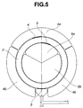
- FIG. 5 schematically illustrates an air vent structure in an injection mold used in Examples 1 and 5.
- FIG. 6 schematically illustrates an air vent structure in an injection mold used in Examples 2 and 6.
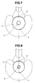
- FIG. 7 schematically illustrates an air vent structure in an injection mold used in Examples 3 and 7.
- FIG. 8 schematically illustrates an air vent structure in an injection mold used in Example 4.
- FIG. 9 schematically illustrates an air vent structure in an injection mold used in Comparative Examples 1 and 5.
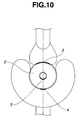
- FIG. 10 schematically illustrates an air vent structure in an injection mold used in Comparative Examples 2 and 6.
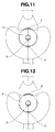
- FIG. 11 schematically illustrates an air vent structure in an injection mold used in Comparative Examples 3 and 7.
- FIG. 12 schematically illustrates an air vent structure in an injection mold used in Comparative Example 4.
- the molding material fed from an inlet gate into a cavity is divided into at least two streams that flow through the cavity and then meet at a confluent point so that the molding material portions are joined together along a joint plane.
- At least two air vent gates in fluid communication with the cavity are spaced apart from the confluent point such that the area of the joint plane may become larger than the area of the joint plane given by the molding material portions when the air vent gates are disposed at the confluent point.
- an injection mold as embodied by the invention is illustrated in a plan view.
- the mold is used in producing annular or ring-shaped articles.
- a mold body 1 is formed with a cavity 2 defining an annular ring shape.
- the cavity 2 has an outside and an inside as viewed in the plan view.
- the mold is provided with an inlet gate 3 for feeding and injecting a molding material into the cavity 2.
- the molding material fed from the inlet gate 3 is divided into two streams which flow clockwise and counter-clockwise, as viewed in the figure, and then meet at an outside position P and an inside position Q on the cavity wall which are located 180° remote from the center of the inlet gate 3, that is, diametrically opposed positions.
- the mold is further provided with an outside air vent gate 4 and an inside air vent gate 5.
- These air vent gates 4 and 5 are located in proximity to the positions P and Q located 180° remote from the inlet gate 3, with the outside air vent gate 4 being shifted left from the 180° remote position and the inside air vent gate 5 being shifted right from the 180° remote position.
- the molding material flows through the cavity 2 in two clockwise and counter-clockwise streams to displace or purge the air in the cavity 2 from the air vent gates 4 and 5.
- the two streams meet at a confluent interface while the leading portions of the molding material streams are being discharged or purged from the air vent gates 4 and 5.
- the confluent or joint plane S between the molding material streams is in agreement with a line or plane connecting the outside and inside air vent gates 4 and 5.
- the joint plane S between the molding material streams has a larger area so that a higher strength is established thereat.
- the molding material streams meet and joint at the confluent or joint plane S' before the leading portions of the molding material streams are discharged or purged from the air vent gates 4' and 5'. Then a lower strength is established at the joint between molding material streams.
- the joint plane S defined between molding material streams in the mold of FIG. 1 is inclined with respect to the diametrical plane and thus has a larger area.
- the location of the air vent gates 4 and 5 upstream of the 180° remote positions P and Q with respect to the respective streams ensures that the leading portions of the molding material streams are discharged or purged from the air vent gates 4 and 5. Then a better adherence and a higher strength is established at the molding material joint.
- air vent gates are not limited to particular positions insofar as at least two air vent gates are located at such positions as to provide a joint plane of a greater area between molding material streams.
- two air vent gates are preferably located at two outside and inside positions which are spaced apart from the normal joint plane in opposite directions as shown in FIG. 1 (i.e., positions falling outside the joint plane which is symmetrical with respect to the center of the joint plane).
- the outside air vent gate 4 is located at such a position that the angle ⁇ included between a line connecting the gate center to the inside 180° remote position Q and the diametrical line connecting the outside and inside 180° remote positions P and Q is from more than 0° to 45°, especially from 2° to 30°.
- the inside air vent gate 5 is located at such a position that the angle 0 included between a line connecting the gate center to the outside 180° remote position P and the diametrical line connecting the outside and inside 180° remote positions P and Q is from more than 0° to 45°, especially from 2° to 30°.
- the dimensions (width, length and depth) of the air vent gates vary with a particular type of molding material and may be selected as appropriate for the particular molding material used.
- the purged material-receiving space is a region that is disposed contiguous to the air vent gate, and the air-receiving space is a region that is disposed remote from the air vent gate, but contiguous to the purged material-receiving space.
- the reason why the air vent is divided into at least two spaces is that the division of the air vent into a purged material-receiving space and an air-receiving space prevents the air vent from being clogged. This avoids an accidental situation that one air vent is clogged and the molding material is purged into the remaining air vents.
- each air vent is divided into a purged material-receiving space and an air-receiving space.
- each air vent is divided into a purged material-receiving space 4a, 5a and an air-receiving space 4b, 5b in accordance with the purged amount of molding material, which ensures that the purged amounts of molding material in at least two purged material-receiving spaces are equalized, and that the air is completely displaced from the cavity (defining the article shape). This protects molded articles from weld marks and defects by incidental entrapment of air.
- two or more purged material-receiving spaces disposed on the outside and inside and any additional positions of the cavity have close volume fractions.
- the purged material-receiving spaces are designed in a volume ratio of 1:1. Since a certain mold structure makes it difficult to design the spaces to equality, it is recommended that the two purged material-receiving spaces 4a and 5a on the outside and inside be designed in a volume ratio of from 1:0.1 to 1:10, and especially from 1:0.2 to 1:5.
- the resulting situation is approximate to the situation where one air vent is filled and clogged with the purged material, and the desired effect resulting from two or more air vents is not substantially expectable.
- the preferred embodiment of the invention in which the purged amounts of molding material in the purged material-receiving spaces disposed at two or more positions, typically the outside and inside are kept in good balance, is effective for stabilizing the flow of the molding material throughout the cavity.
- the purged material-receiving space 4a, 5a and the air-receiving space 4b, 5b are preferably set in a volume ratio of from 1:0.1 to 1:10, and especially from 1:0.2 to 1:5. This setting is effective for further stabilizing the material joint plane in the molded article.
- the division of the air vent into a purged material-receiving space and an air-receiving space is possible insofar as they can be given approximately the same depth and width as in the air vent gate.
- the injection mold of the invention is typically subjected to surface treatment for improving abrasion resistance, preventing corrosion and improving mold release properties or for any other purpose.
- the surface treatment may be any ordinary mold surface treatment as typified by nickel plating or chromium plating although surface treatment with diamond-like carbon (DLC) or tri-iron tetroxide is preferred.
- DLC diamond-like carbon
- DLC is prepared by decomposing hydrocarbon gases with an arc discharge plasma in high vacuum, electrically accelerating ions and excited molecules in the plasma, and causing them to impinge with sufficient energy, thereby forming a film of DLC.
- the film has a dense amorphous structure and a very smooth surface free of grain boundaries, and exhibits excellent properties including a low friction coefficient, abrasion resistance and mold release.
- the surface treatment with DLC or tri-iron tetroxide achieves a significant improvement in mold release properties, with the following advantages. (1) The defects introduced in molded articles by cutting upon removal thereof from the mold are minimized. (2) The removal of molded articles from the mold is significantly facilitated, and the molding cycle can be reduced. (3) Molded articles can be removed without a need for parting agents, preventing the mold from being contaminated with parting agents and eliminating a need for mold cleaning.
- the shape of articles which can be molded using the inventive mold is not critical insofar as the article shape includes a material joint plane. Better results are obtained with ring-like shapes such as O rings and square rings and frame-like shapes.
- the invention is most effective for ring-shaped molded articles. With respect to O rings which are typical examples of ring-shaped articles, even high-precision seal members for use in aircraft can be produced at a high reliability level. While aircraft O rings are often produced to the specification setting forth a flash thickness of not greater than 0.13 mm, the inventive mold is best suited for such precision molding.
- the material which can be molded using the inventive mold is selected from, for example, thermoplastic resins, thermosetting resins, rubber materials of the millable type, and rubber materials of the liquid type.
- thermoplastic resins thermosetting resins
- rubber materials of the millable type and rubber materials of the liquid type.
- Especially useful materials are rubber materials of the liquid type such as liquid silicone rubber compositions and liquid fluororubber compositions, with the liquid fluororubber compositions being most useful.
- liquid fluororubber compositions are those based on a base polymer having a perfluoropolyether backbone, such as SIFEL produced by Shin-Etsu Chemical Co., Ltd. These are often used in the manufacture of O rings for aircraft requiring high precision and high reliability.
- an appropriate injection rate is 0.01 to 1,000 cc/sec.
- An injection rate below the range may lead to a substantial loss of production efficiency whereas a rate above the range may cause air to be entrapped in the molded articles and scorching.
- a more appropriate injection rate is 0.1 to 500 cc/sec.
- the molding temperature is in the range of 80 to 200°C, at which the molding material is held for a time for crosslinking, typically 1 to 600 seconds.
- a lower molding temperature may require a longer crosslinking time, leading to a loss of production efficiency.
- a higher molding temperature may cause crosslinking to proceed while the material flows through the cavity, so that the material loses flow, with a failure of molding.
- the molding temperature is set in the range of 100 to 180°C.
- the materials were injected into the injection molds shown in Table 1 and FIGS. 5 to 12 under optimum conditions shown in Tables 2 to 6, producing O rings.
- the rings were post cured at 200°C for 4 hours for stabilizing the physical properties thereof.
- the O rings produced in Examples 1 and 2 using the mold having the air vent structure according to the invention showed a satisfactory outer appearance whereas the O rings of the same shape produced in Comparative Examples 1 and 2 using the mold having a conventional air vent structure showed an apparently deficient outer appearance.
- the strength and elongation measurements of the O rings of Comparative Examples 1 and 2 were lower than in Examples 1 and 2. An observation of O ring samples that broke during the strength measurement revealed that all the O ring samples of Comparative Examples 1 and 2 broke at the material joint whereas the O ring samples of Examples 1 and 2 broke at positions other than the material joint.
- the O rings of Comparative Examples 3 and 4 have no deficiency in outer appearance probably due to their small size, but their elongation is apparently lower than that of the O rings of the same shape produced in Examples 3 and 4 using the mold having the air vent structure according to the invention.
- liquid silicone rubber composition As compared with the liquid fluororubber compositions, the liquid silicone rubber composition developed few weld marks. With respect to strength and elongation, however, a definite difference was found between Examples and Comparative Examples.
Landscapes
- Engineering & Computer Science (AREA)
- Manufacturing & Machinery (AREA)
- Mechanical Engineering (AREA)
- Moulds For Moulding Plastics Or The Like (AREA)
- Gasket Seals (AREA)
- Sealing Devices (AREA)
Abstract
Description
| Mold No. |
O ring shape | Air vent | Cavity number in a mold |
Figure | |||
| Inner diameter (mm) |
Thickness (mm) |
Gate position | Gate size (mm) |
|
|||
| 1 | 24.99 | 3.53 | inventive | 6.0 | yes | 4 | FIG. 5 |
| 2 | 13.94 | 2.62 | inventive | 2.0 | no | 4 | FIG. 6 |
| 3 | 3.68 | 1.78 | inventive | 0.85 | no | 1 | FIG. 7 |
| 4 | 0.74 | 1.78 | inventive | 0.6 | no | 1 | FIG. 8 |
| 5 | 24.99 | 3.53 | conventional | 6.0 | no | 4 | FIG. 9 |
| 6 | 13.94 | 2.62 | conventional | 2.0 | no | 4 | FIG. 10 |
| 7 | 3.68 | 1.78 | conventional | 0.85 | no | 1 | FIG. 11 |
| 8 | 0.74 | 1.78 | conventional | 0.6 | no | 1 | FIG. 12 |
| Material, molding conditions, evaluation | Example 1 | Example 2 | Example 3 | Example 4 |
| Material | SIFEL 4750 | SIFEL 4750 | SIFEL 4750 | SIFEL 4750 |
| Mold No. | 1 | 2 | 3 | 4 |
| Molding machine | 10 ton | 7 ton | 7 ton | 7 ton |
| Molding temp. (°C) | 120 | 120 | 120 | 120 |
| Injection time (sec) | 30 | 30 | 20 | 20 |
| O ring strength (MPa) | 5.2 | 5.5 | - | - |
| O ring elongation (%) | 100 | 90 | 110 | 120 |
| Visual appearance | Good | Good | Good | Good |
| Material, molding conditions, evaluation | Comparative Example 1 | Comparative Example 2 | Comparative Example 3 | Comparative Example 4 |
| Material | SIFEL 4750 | SIFEL 4750 | SIFEL 4750 | SIFEL 4750 |
| Mold No. | 5 | 6 | 7 | 8 |
| Molding machine | 10 ton | 7 ton | 7 ton | 7 ton |
| Molding temp. (°C) | 120 | 120 | 120 | 120 |
| Injection time (sec) | 30 | 30 | 20 | 20 |
| O ring strength (MPa) | 3.2 | 3.4 | - | - |
| O ring elongation (%) | 50 | 60 | 70 | 50 |
| Visual appearance | Weld marks | Weld marks | Good | Good |
| Material, molding conditions, evaluation | Example 5 | Example 6 | Example 7 |
| Material | SIFEL 3701 | SIFEL 3701 | SIFEL 3701 |
| Mold No. | 1 | 2 | 3 |
| Molding machine | 10 ton | 7 ton | 7 ton |
| Molding temp. (°C) | 130 | 130 | 130 |
| Injection time (sec) | 10 | 5 | 5 |
| O ring strength (MPa) | 6.1 | 6.5 | - |
| O ring elongation (%) | 150 | 190 | 170 |
| Visual appearance | Good | Good | Good |
| Material, molding conditions, evaluation | Comparative Example 5 | Comparative Example 6 | Comparative Example 7 |
| Material | SIFEL 3701 | SIFEL 3701 | SIFEL 3701 |
| Mold No. | 5 | 6 | 7 |
| Molding machine | 10 ton | 7 ton | 7 ton |
| Molding temp. (°C) | 130 | 130 | 130 |
| Injection time (sec) | 10 | 5 | 5 |
| O ring strength (MPa) | 5.2 | 5.5 | - |
| O ring elongation (%) | 130 | 130 | 150 |
| Visual appearance | Weld marks | Good | Good |
| Material, molding conditions, evaluation | Example 8 | Example 9 | Comparative Example 8 | Comparative Example 9 |
| Material | KE 1990-60 | KE 1990-60 | KE 1990-60 | KE 1990-60 |
| Mold No. | 1 | 2 | 5 | 6 |
| Molding machine | 10 ton | 7 ton | 10 ton | 7 ton |
| Molding temp. (°C) | 140 | 140 | 140 | 140 |
| Injection time (sec) | 10 | 5 | 10 | 5 |
| O ring strength (MPa) | 6.5 | 6.8 | 5.1 | 4.9 |
| O ring elongation (%) | 210 | 220 | 170 | 180 |
| Visual appearance | Good | Good | Good | Good |
Claims (8)
- An injection mold comprising a cavity, an inlet gate for feeding a molding material into the cavity therethrough, and at least two air vent gates in fluid communication with the cavity wherein the molding material fed from the inlet gate into the cavity is divided into at least two streams that flow through the cavity and then meet at a confluent point so that the molding material portions are joined together along a joint plane, and
the air vent gates are spaced apart from the confluent point such that the area of the joint plane may become larger than the area of the joint plane given by the molding material portions when the air vent gates are disposed at the confluent point. - The injection mold of claim 1 wherein the cavity is of a ring shape having an outside and an inside in a plan view, and the air vent gates are disposed on the outside and inside and in proximity to the position located 180° remote from the inlet gate, with one air vent gate being shifted right from the 180° remote position and the other air vent gate being shifted left from the 180° remote position.
- The injection mold of claim 2 wherein the outside and inside air vents have purged molding material-receiving spaces in a volume ratio from 1:0.1 to 1:10.
- The injection mold of claim 2 or 3 which is used in molding of a ring-shaped article.
- A method for manufacturing an injection molded article in the injection mold of any one of claims 1 to 4, the method comprising the step of injecting a molding material into the cavity.
- The method of claim 5 wherein the molding material is a liquid rubber composition.
- The method of claim 6 wherein the liquid rubber composition is a liquid fluororubber composition primarily comprising a base polymer having perfluoropolyether backbone.
- The method of claim 5, 6 or 7 wherein the molded article is an O ring or square ring.
Applications Claiming Priority (2)
| Application Number | Priority Date | Filing Date | Title |
|---|---|---|---|
| JP2001353046 | 2001-11-19 | ||
| JP2001353046A JP3981808B2 (en) | 2001-11-19 | 2001-11-19 | Injection mold and method for producing injection molded product using the same |
Publications (3)
| Publication Number | Publication Date |
|---|---|
| EP1312455A2 true EP1312455A2 (en) | 2003-05-21 |
| EP1312455A3 EP1312455A3 (en) | 2003-06-25 |
| EP1312455B1 EP1312455B1 (en) | 2008-06-04 |
Family
ID=19165129
Family Applications (1)
| Application Number | Title | Priority Date | Filing Date |
|---|---|---|---|
| EP02257939A Expired - Lifetime EP1312455B1 (en) | 2001-11-19 | 2002-11-18 | Injection mold and method for manufacturing injection molded articles |
Country Status (4)
| Country | Link |
|---|---|
| US (1) | US6855286B2 (en) |
| EP (1) | EP1312455B1 (en) |
| JP (1) | JP3981808B2 (en) |
| DE (1) | DE60226940D1 (en) |
Cited By (9)
| Publication number | Priority date | Publication date | Assignee | Title |
|---|---|---|---|---|
| WO2005084487A3 (en) * | 2004-03-01 | 2005-10-27 | Glaxosmithkline Consumer Healt | Injection moulding process |
| EP1645385A1 (en) * | 2004-10-11 | 2006-04-12 | Tecnocad Progetti Spa | Method and system for producing a foamed article |
| WO2007098740A1 (en) * | 2006-03-03 | 2007-09-07 | Webasto Ag | Device and method for foaming or injection-molding a plastic frame of a planar workpiece |
| FR2925387A1 (en) * | 2007-12-21 | 2009-06-26 | Valeo Systemes Thermiques | Plastic part molding method for fabricating monoblock manifold of motor vehicle, involves spreading plastic material in mold along fronts of material, where fronts form pipe for exhausting gas towards degassing orifices of mold |
| KR20120098691A (en) * | 2009-10-15 | 2012-09-05 | 니치아 카가쿠 고교 가부시키가이샤 | Light-emitting device and method for manufacturing same |
| US8313681B2 (en) | 2008-05-23 | 2012-11-20 | Nok Corporation | Method of manufacturing seal part |
| EP2097626A4 (en) * | 2006-12-28 | 2013-02-13 | Borgwarner Inc | Plastic fans having improved fan ring weld line strength |
| EP2664434A1 (en) * | 2012-04-17 | 2013-11-20 | D.W. Plastics NV | Injection moulding method for forming a bottle crate, bottle crate and corresponding apparatus for obtaining such bottle crate |
| US9718226B2 (en) | 2011-04-19 | 2017-08-01 | Suzuki Motor Corporation | Method of injection molding |
Families Citing this family (18)
| Publication number | Priority date | Publication date | Assignee | Title |
|---|---|---|---|---|
| US6939490B2 (en) * | 2002-12-11 | 2005-09-06 | Honeywell International Inc. | Process for unidirectional infiltration of preform with molten resin or pitch |
| JP4317375B2 (en) * | 2003-03-20 | 2009-08-19 | 株式会社日立製作所 | Nanoprint apparatus and fine structure transfer method |
| GB0307095D0 (en) * | 2003-03-27 | 2003-04-30 | Imagination Tech Ltd | Improvements to a tiling system for 3d rendered graphics |
| EP1568474B1 (en) * | 2004-02-27 | 2008-07-23 | INSA (Institut National des Sciences Appliqées) | Process and installation for molding an optical lens |
| US20060100343A1 (en) * | 2004-11-10 | 2006-05-11 | Shin-Etsu Chemical Co., Ltd. | Fluororubber/silicone rubber blend and molded rubber articles |
| JP2006205580A (en) * | 2005-01-28 | 2006-08-10 | Nishikawa Kasei Co Ltd | Resin ring-shaped product and injection molding method thereof |
| FR2886574B1 (en) * | 2005-06-06 | 2009-07-10 | Essilor Int | MOLD AND METHOD OF MOLDING, PARTICULARLY BY REACTIVE INJECTION MOLDING, ESPECIALLY OF AN OPTICAL ELEMENT IN POLYMERIC MATERIAL |
| CA2662120A1 (en) * | 2006-09-06 | 2008-03-13 | Prime Polymer Co., Ltd. | Injection molding metal mold and shaped article |
| JP5072346B2 (en) * | 2006-12-27 | 2012-11-14 | 旭化成メディカル株式会社 | Cylindrical container for body fluid treatment device, body fluid treatment device, and method for molding tubular container for body fluid treatment device |
| JP5393985B2 (en) * | 2008-01-31 | 2014-01-22 | 第一電子工業株式会社 | Insulator molding method, mold structure, and connector using insulator manufactured by the molding method |
| JP5846039B2 (en) * | 2012-05-14 | 2016-01-20 | トヨタ紡織株式会社 | Manufacturing method of molded products |
| JP2014065266A (en) * | 2012-09-27 | 2014-04-17 | Asahi Electric Works Ltd | Injection molding and method for manufacturing the same |
| AT514828B1 (en) * | 2013-09-24 | 2015-06-15 | Hoerbiger Kompressortech Hold | Method and mold for the production of sealing plates by injection molding as well as correspondingly produced sealing plates |
| US9308702B2 (en) | 2014-02-25 | 2016-04-12 | The Boeing Company | Method and apparatus for making preformed seals |
| JP6585451B2 (en) * | 2015-09-30 | 2019-10-02 | 住友理工株式会社 | Rubber gasket for fuel cell, method for producing fuel cell seal body, and water-based mold release agent used therefor |
| JP6713830B2 (en) * | 2016-05-26 | 2020-06-24 | 株式会社デンソー | Gear, gear transmission mechanism, and method of manufacturing gear |
| CN116162316B (en) * | 2022-12-27 | 2024-06-25 | 中铁工程装备集团有限公司 | High-performance fluororubber composition for sealing of heading machine, sealing ring and preparation method of sealing ring |
| CN119974418B (en) * | 2025-04-15 | 2025-07-11 | 成都龙源新材料科技有限公司 | Forming die of rope saw cutting polyurethane wear-resistant rubber ring and use method |
Family Cites Families (12)
| Publication number | Priority date | Publication date | Assignee | Title |
|---|---|---|---|---|
| JP3299419B2 (en) * | 1995-08-04 | 2002-07-08 | エヌオーケー株式会社 | Seal ring manufacturing method |
| US3880978A (en) * | 1974-04-23 | 1975-04-29 | Ford Motor Co | Method for forming a remote annular rim of plastic material |
| JPS5722031A (en) * | 1980-07-15 | 1982-02-04 | Fuji Elelctrochem Co Ltd | Molding method of circular resin gasket |
| US4399093A (en) * | 1981-06-26 | 1983-08-16 | Whirlpool Corporation | Injection molding method and equipment |
| JPH0692099B2 (en) * | 1990-10-19 | 1994-11-16 | 豊田合成株式会社 | Mold for molding |
| JP2708971B2 (en) * | 1991-04-09 | 1998-02-04 | ポリプラスチックス株式会社 | Injection molding method, injection mold and injection molded product |
| JPH06328520A (en) * | 1993-05-18 | 1994-11-29 | Fuji Seiki Kk | Mold for molding half case for floppy disk |
| JP3411142B2 (en) * | 1994-12-20 | 2003-05-26 | 株式会社日立製作所 | Injection molded article, its manufacturing method, and its mold |
| JPH09239786A (en) * | 1996-03-04 | 1997-09-16 | Fuji Elelctrochem Co Ltd | Mold for resin-molded rotor and resin-molded rotor molded by the mold |
| JPH1176466A (en) * | 1997-09-10 | 1999-03-23 | Bridgestone Sports Co Ltd | Golf ball injection mold and golf ball |
| JPH1177715A (en) * | 1997-09-17 | 1999-03-23 | Nok Corp | Mold |
| JP3500932B2 (en) * | 1997-09-24 | 2004-02-23 | Nok株式会社 | Mold and method for forming seal ring having cut portion |
-
2001
- 2001-11-19 JP JP2001353046A patent/JP3981808B2/en not_active Expired - Lifetime
-
2002
- 2002-11-18 EP EP02257939A patent/EP1312455B1/en not_active Expired - Lifetime
- 2002-11-18 DE DE60226940T patent/DE60226940D1/en not_active Expired - Fee Related
- 2002-11-19 US US10/298,926 patent/US6855286B2/en not_active Expired - Fee Related
Cited By (11)
| Publication number | Priority date | Publication date | Assignee | Title |
|---|---|---|---|---|
| WO2005084487A3 (en) * | 2004-03-01 | 2005-10-27 | Glaxosmithkline Consumer Healt | Injection moulding process |
| EP1645385A1 (en) * | 2004-10-11 | 2006-04-12 | Tecnocad Progetti Spa | Method and system for producing a foamed article |
| WO2007098740A1 (en) * | 2006-03-03 | 2007-09-07 | Webasto Ag | Device and method for foaming or injection-molding a plastic frame of a planar workpiece |
| EP2097626A4 (en) * | 2006-12-28 | 2013-02-13 | Borgwarner Inc | Plastic fans having improved fan ring weld line strength |
| FR2925387A1 (en) * | 2007-12-21 | 2009-06-26 | Valeo Systemes Thermiques | Plastic part molding method for fabricating monoblock manifold of motor vehicle, involves spreading plastic material in mold along fronts of material, where fronts form pipe for exhausting gas towards degassing orifices of mold |
| US8313681B2 (en) | 2008-05-23 | 2012-11-20 | Nok Corporation | Method of manufacturing seal part |
| KR20120098691A (en) * | 2009-10-15 | 2012-09-05 | 니치아 카가쿠 고교 가부시키가이샤 | Light-emitting device and method for manufacturing same |
| EP2490269A4 (en) * | 2009-10-15 | 2014-07-30 | Nichia Corp | LIGHT EMITTING DEVICE AND METHOD FOR MANUFACTURING THE SAME |
| US9705048B2 (en) | 2009-10-15 | 2017-07-11 | Nichia Corporation | Light-emitting device and method for manufacturing same |
| US9718226B2 (en) | 2011-04-19 | 2017-08-01 | Suzuki Motor Corporation | Method of injection molding |
| EP2664434A1 (en) * | 2012-04-17 | 2013-11-20 | D.W. Plastics NV | Injection moulding method for forming a bottle crate, bottle crate and corresponding apparatus for obtaining such bottle crate |
Also Published As
| Publication number | Publication date |
|---|---|
| US6855286B2 (en) | 2005-02-15 |
| EP1312455A3 (en) | 2003-06-25 |
| US20030122281A1 (en) | 2003-07-03 |
| EP1312455B1 (en) | 2008-06-04 |
| JP2003145588A (en) | 2003-05-20 |
| JP3981808B2 (en) | 2007-09-26 |
| DE60226940D1 (en) | 2008-07-17 |
Similar Documents
| Publication | Publication Date | Title |
|---|---|---|
| EP1312455B1 (en) | Injection mold and method for manufacturing injection molded articles | |
| US8579257B2 (en) | Valve assembly with annular sealing member having elongated-circle cross-sectional shape | |
| CN101588908B (en) | Nozzle assembly for injector | |
| EP2926851B1 (en) | Gasket for prefilled syringe, and production method therefor | |
| RU2004121974A (en) | PRESS FORM FOR PRESSURE CASTING, METHOD FOR CASTING OF PRESSURE AND PACKAGING CONTAINER WITH EQUIPMENT FOR OPENING, OBTAINED BY PRESSURE CASTING | |
| KR101388293B1 (en) | Elbow correction mold device | |
| EP3437823B1 (en) | Gas discharge structure | |
| US5217732A (en) | Flash suppressing mold apparatus | |
| CN217747719U (en) | Injection molding type connecting mechanism | |
| JPH0515526B2 (en) | ||
| JP5824172B1 (en) | Gear pump component and manufacturing method thereof | |
| CN210880461U (en) | Spring air hole sleeve | |
| JP3658119B2 (en) | Piston for composite resin molded body and manufacturing method thereof | |
| CN1119223C (en) | Matched-mold forming device for producing resin product | |
| CN218286304U (en) | Airtight structure of insert injection molding product and insert injection molding product | |
| USRE25560E (en) | Method of making a rigid resilient | |
| JPS6143532A (en) | Vent device of injection molding machine | |
| US20050206036A1 (en) | Method for producing a throttle valve | |
| JP4303580B2 (en) | Injection mold, and method for manufacturing seal ring using the mold | |
| CN114845852B (en) | Apparatus and method for molding bottle preforms | |
| JP2000202870A (en) | Injection mold | |
| CN208341699U (en) | A kind of mold for the casting coating on skeleton | |
| CN116323132A (en) | Mold part for injection molding of thermoplastic resin and injection molding method of thermoplastic resin | |
| CN112403068A (en) | Filter | |
| JP2989471B2 (en) | Mechanical parts made of thermoplastic resin by hollow injection molding |
Legal Events
| Date | Code | Title | Description |
|---|---|---|---|
| PUAI | Public reference made under article 153(3) epc to a published international application that has entered the european phase |
Free format text: ORIGINAL CODE: 0009012 |
|
| PUAL | Search report despatched |
Free format text: ORIGINAL CODE: 0009013 |
|
| AK | Designated contracting states |
Designated state(s): AT BE BG CH CY CZ DE DK EE ES FI FR GB GR IE IT LI LU MC NL PT SE SK TR |
|
| AX | Request for extension of the european patent |
Extension state: AL LT LV MK RO SI |
|
| AK | Designated contracting states |
Designated state(s): AT BE BG CH CY CZ DE DK EE ES FI FR GB GR IE IT LI LU MC NL PT SE SK TR |
|
| AX | Request for extension of the european patent |
Extension state: AL LT LV MK RO SI |
|
| 17P | Request for examination filed |
Effective date: 20031009 |
|
| AKX | Designation fees paid |
Designated state(s): DE FR GB |
|
| 17Q | First examination report despatched |
Effective date: 20060907 |
|
| GRAP | Despatch of communication of intention to grant a patent |
Free format text: ORIGINAL CODE: EPIDOSNIGR1 |
|
| GRAS | Grant fee paid |
Free format text: ORIGINAL CODE: EPIDOSNIGR3 |
|
| GRAA | (expected) grant |
Free format text: ORIGINAL CODE: 0009210 |
|
| AK | Designated contracting states |
Kind code of ref document: B1 Designated state(s): DE FR GB |
|
| REG | Reference to a national code |
Ref country code: GB Ref legal event code: FG4D |
|
| REF | Corresponds to: |
Ref document number: 60226940 Country of ref document: DE Date of ref document: 20080717 Kind code of ref document: P |
|
| PGFP | Annual fee paid to national office [announced via postgrant information from national office to epo] |
Ref country code: DE Payment date: 20081114 Year of fee payment: 7 |
|
| PLBE | No opposition filed within time limit |
Free format text: ORIGINAL CODE: 0009261 |
|
| STAA | Information on the status of an ep patent application or granted ep patent |
Free format text: STATUS: NO OPPOSITION FILED WITHIN TIME LIMIT |
|
| PGFP | Annual fee paid to national office [announced via postgrant information from national office to epo] |
Ref country code: FR Payment date: 20081112 Year of fee payment: 7 |
|
| 26N | No opposition filed |
Effective date: 20090305 |
|
| PGFP | Annual fee paid to national office [announced via postgrant information from national office to epo] |
Ref country code: GB Payment date: 20081112 Year of fee payment: 7 |
|
| GBPC | Gb: european patent ceased through non-payment of renewal fee |
Effective date: 20091118 |
|
| REG | Reference to a national code |
Ref country code: FR Ref legal event code: ST Effective date: 20100730 |
|
| PG25 | Lapsed in a contracting state [announced via postgrant information from national office to epo] |
Ref country code: FR Free format text: LAPSE BECAUSE OF NON-PAYMENT OF DUE FEES Effective date: 20091130 |
|
| PG25 | Lapsed in a contracting state [announced via postgrant information from national office to epo] |
Ref country code: DE Free format text: LAPSE BECAUSE OF NON-PAYMENT OF DUE FEES Effective date: 20100601 |
|
| PG25 | Lapsed in a contracting state [announced via postgrant information from national office to epo] |
Ref country code: GB Free format text: LAPSE BECAUSE OF NON-PAYMENT OF DUE FEES Effective date: 20091118 |