EP1311079B1 - Phase controlled optical signal transmission system - Google Patents
Phase controlled optical signal transmission system Download PDFInfo
- Publication number
- EP1311079B1 EP1311079B1 EP02292723A EP02292723A EP1311079B1 EP 1311079 B1 EP1311079 B1 EP 1311079B1 EP 02292723 A EP02292723 A EP 02292723A EP 02292723 A EP02292723 A EP 02292723A EP 1311079 B1 EP1311079 B1 EP 1311079B1
- Authority
- EP
- European Patent Office
- Prior art keywords
- optical
- signal
- transmission system
- link
- transmission
- Prior art date
- Legal status (The legal status is an assumption and is not a legal conclusion. Google has not performed a legal analysis and makes no representation as to the accuracy of the status listed.)
- Expired - Lifetime
Links
- 230000003287 optical effect Effects 0.000 title claims abstract description 127
- 230000008054 signal transmission Effects 0.000 title 1
- 230000005540 biological transmission Effects 0.000 claims abstract description 67
- 230000003595 spectral effect Effects 0.000 claims abstract description 30
- 238000001914 filtration Methods 0.000 claims abstract description 14
- 230000010363 phase shift Effects 0.000 claims abstract description 7
- 239000006185 dispersion Substances 0.000 claims description 36
- 239000000835 fiber Substances 0.000 claims description 23
- 238000001228 spectrum Methods 0.000 claims description 18
- 238000012546 transfer Methods 0.000 claims description 14
- 230000001186 cumulative effect Effects 0.000 claims description 9
- 230000000737 periodic effect Effects 0.000 claims description 8
- 230000008878 coupling Effects 0.000 claims description 5
- 238000010168 coupling process Methods 0.000 claims description 5
- 238000005859 coupling reaction Methods 0.000 claims description 5
- 230000000875 corresponding effect Effects 0.000 description 7
- 230000035945 sensitivity Effects 0.000 description 7
- 230000015556 catabolic process Effects 0.000 description 5
- 238000006731 degradation reaction Methods 0.000 description 5
- 238000000034 method Methods 0.000 description 5
- 230000008901 benefit Effects 0.000 description 4
- 230000009021 linear effect Effects 0.000 description 4
- 230000005374 Kerr effect Effects 0.000 description 3
- 239000000969 carrier Substances 0.000 description 3
- 230000033764 rhythmic process Effects 0.000 description 3
- 238000004088 simulation Methods 0.000 description 3
- 230000001052 transient effect Effects 0.000 description 3
- 230000003321 amplification Effects 0.000 description 2
- 238000002474 experimental method Methods 0.000 description 2
- 230000006872 improvement Effects 0.000 description 2
- 230000009022 nonlinear effect Effects 0.000 description 2
- 238000003199 nucleic acid amplification method Methods 0.000 description 2
- 230000008569 process Effects 0.000 description 2
- 238000013459 approach Methods 0.000 description 1
- 230000009286 beneficial effect Effects 0.000 description 1
- 230000008033 biological extinction Effects 0.000 description 1
- 239000000470 constituent Substances 0.000 description 1
- 230000002596 correlated effect Effects 0.000 description 1
- 238000001514 detection method Methods 0.000 description 1
- 230000000694 effects Effects 0.000 description 1
- 238000011156 evaluation Methods 0.000 description 1
- 230000002349 favourable effect Effects 0.000 description 1
- 230000009467 reduction Effects 0.000 description 1
- 238000009877 rendering Methods 0.000 description 1
- 239000004065 semiconductor Substances 0.000 description 1
- 230000001960 triggered effect Effects 0.000 description 1
- 238000011144 upstream manufacturing Methods 0.000 description 1
- 238000012795 verification Methods 0.000 description 1
Images

Classifications
-
- H—ELECTRICITY
- H04—ELECTRIC COMMUNICATION TECHNIQUE
- H04B—TRANSMISSION
- H04B10/00—Transmission systems employing electromagnetic waves other than radio-waves, e.g. infrared, visible or ultraviolet light, or employing corpuscular radiation, e.g. quantum communication
- H04B10/25—Arrangements specific to fibre transmission
- H04B10/2507—Arrangements specific to fibre transmission for the reduction or elimination of distortion or dispersion
- H04B10/2543—Arrangements specific to fibre transmission for the reduction or elimination of distortion or dispersion due to fibre non-linearities, e.g. Kerr effect
- H04B10/255—Self-phase modulation [SPM]
Definitions
- the invention lies in the field of systems telecommunication optics for the transmission of digital data. It relates more particularly to techniques for transmitting digital optical signals to broadband by long distance links using fiber optics and / or through optical switches.
- An optical transmission system includes typically at least one optical transmitter connected to a optical receiver via an optical link which can consist of a single fiber or several fiber sections linked together by amplifiers optics and / or more complex coupling media comprising for example switches produced by means of couplers, guides and optical gates.
- a transmitter includes an optical signal source of which the function is to apply an optical carrier wave modulation according to the information to be transmitted.
- the same link can carry several signals carried by carrier waves of different wavelengths.
- WDM length-division multiplex transmission system wave
- Modulation formats generally adopted are NRZ or RZ type. They consist to encode binary information by varying the carrier wave power between two levels: one level low corresponding to an extinction of the wave and a level high corresponding to maximum optical power. These level variations are triggered at imposed times by a clock rhythm of fixed period T which thus defines successive time cells allocated to the data binaries to transmit. By convention, low levels and highs usually represent binary values "0" and "1" respectively.
- Amplitude modulation technique often designated by "ASK” (from the English “Amplitude-Shift Keying"), has the advantage of a relatively easy implementation using proven optical components, but it has however the disadvantage of being sensitive to dispersion chromatic. Although there are compensation for chromatic dispersion, such as so-called “DCF” fibers Fiber "), the compensations obtained are often imperfect, especially when it comes to compensating WDM channels distributed over a wide spectral band.
- a wave on emission, a wave is applied carries an optical phase shift of the order of 180 ° in absolute value inside each cell which corresponds to a logical "0" which precedes or succeeds any cell containing a logical "1".
- the received optical signal in reception, we can convert the received optical signal into an electrical signal in the same way as for modulated signal in NRZ format, that is to say by means of a simple photodetector.
- PSBT modulation In addition to improving the resistance to dispersion chromatic, PSBT modulation also has the property that the resulting signal spectrum is two times less wider than NRZ modulation, which is advantageous for so-called dense WDM transmissions, that is to say of which the spectral interval between WDM channels is small.
- PSBT modulation finds its limits, however when nonlinear optical phenomena become important. This is the case for example when increasing the optical signal strength to increase distances of transmission. We then observe that for a value of the cumulative chromatic dispersion of the link the quality of received signal undergoes degradation which strongly depends on the wavelength of the optical signal carrier. The system therefore becomes less tolerant of chromatic dispersion, this which limits the possibilities of transmitting WDM signals distributed over a wide spectral band, over long distance and without intermediate amplifications.
- Optical frequency modulation or "FSK” presents however the downside that the resulting signal is sensitive to the chromatic dispersion.
- Optical phase modulation or "PSK” (from the English “Phase-Shift Keying") is less sensitive chromatic dispersion but imposes a perfect signal phase stability to allow good detection at the receptor level.
- DPSK differential optical phase modulation
- PSK or DPSK modulations entail a spectral width of the signal which is the same as with the modulation format NRZ, therefore less favorable than PSBT modulation for dense WDM transmissions.
- the object of the invention is therefore to propose a system of transmission using PSBT modulation without chirp transient, but suitable for rendering the transmitted signal less sensitive to both chromatic dispersion and the Kerr effect and more specifically the self-modulation of phase.
- the subject of the invention is a system transmission for phase-controlled optical signal, this signal being modulated to the rhythm of a clock of period T which defines successive time cells delimiting in the signal of low levels or high levels of modulation an optical carrier wave of optical frequency f0, said signal with internal optical phase shift of each time cell that delimits a low level of power and which precedes or succeeds a cell which defines a high level of power, said system comprising an optical link capable of transmitting said phase controlled signal from an input end to an output end to provide a signal corresponding output, said system being characterized in that that it includes corrective optical means coupled to said outlet end and / or inserted in one or more points of said optical link, these correcting means applying optical filtering to the signal present at said outlet end and / or at said points of said link optical, this filtering being calibrated so as to compensate for a broadening of spectrum as said phase controlled signal can undergo by phase self-modulation during its transmission in said optical link.
- the invention takes into account the observation that a signal in PSBT modulation format transmitted in a non-medium linear undergoes an enlargement by phase of its spectrum as it propagates in this medium and that applying optical filtering designed to restore the spectrum width of the transmitted signal to that of the initial PSBT signal improves the signal quality.
- the filter transfer function is calibrated to produce a decrease in spectrum width sufficient to eliminate part of the components spectral created by phase self-modulation, without however excessively attenuate the central part of the spectrum as this would result in a loss of information contained in the signal, which would be contrary to the desired goal.
- the choice of filtering can be considered as a compromise between compensation for enlargement of the spectrum and the resulting loss of information.
- said means corrective optics consist of an optical filter coupled to said outlet end and having a function of transfer, expressing the variations according to the optical frequency f of its transmission coefficient, approximately Gaussian in the vicinity of f0, centered on f0, with a half-height spectral width between 0.5 / T and 1.25 / T, and advantageously substantially equal to 0.75 / T.
- said fibers corrective optical means consist of N filters optics respectively coupled to said N ends of output of said sections and such as the transfer function an equivalent filter formed by the cascade coupling said N filters, expressing the variations as a function of the optical frequency f of its transmission coefficient, either approximately Gaussian in the vicinity of f0, centered on f0, with a spectral width at half height between 0.5 / T and 1.25 / T, and advantageously substantially equal to 0.75 / T.
- the or each of the optical filters (FG) will be a periodic filter with a free spectral range expressed in frequencies greater than 1 / T.
- the invention also applies to optical transmission for multiplexed PSBT format signals in wavelength.
- a system is therefore provided for transmit a multiplex formed by several optical signals with controlled phase carried respectively by several waves optical carriers of successive optical frequencies with a given frequency offset.
- the or each of the optical filters will advantageously be a filter periodic with a free spectral range expressed in frequencies equal to said frequency offset. Thanks to that layout it only takes one filter to process simultaneously the different signals forming the multiplex.
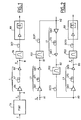
- Figures 1 and 2 show schematically and by way of example two optical transmission systems according to the invention.
- the system comprises a optical link L composed of a single section and arranged between a TX transmitter and an RX receiver.
- a source signal for example an electrical signal E modulated at NRZ format to the rhythm of a clock of period T
- the transmitter TX is able to deliver an optical signal with controlled phase S modulated at the same clock rate in PSBT format, such that detailed in the aforementioned documents.
- the RX receiver basically has a preamplifier optics followed by a photodetector.
- Connection L has an inlet end A provided to receive the signal S and an output end B, located near the RX receiver and designed to deliver a corresponding output signal R.
- the link L is mainly consisting of an LF transmission fiber and an optical emission amplifier OA disposed between TX transmitter and LF fiber.
- an optical preamplifier OA 'reception can also be provided downstream of the fiber LF.
- the output signal R would be coupled directly to the RX receiver, or possibly through a compensation element of DCF chromatic dispersion.
- a centered bandpass filter on the frequency of a signal carrier wave can also be provided upstream of the receiver, for example to extract a channel in the case of a WDM transmission or to attenuate noise outside the signal band.
- the transmission coefficient of the filter as a function of the optical frequency always has a very wide spectral width higher than the 1 / T clock frequency of modulation of signal.
- the length of the LF fiber but also compensate for the increase in attenuation which results in increasing the optical power of the signal injected into the LF fiber. Beyond a certain power, fiber is the seat of nonlinear optical phenomena (Kerr effect) important.
- FIG. 3 shows in solid lines an approximate curve of the spectrum of the transmitted signal S modulated in PSBT format.
- This spectrum which expresses the variations of the normalized power spectral density FT 2 (S) as a function of the optical frequency f corresponds to a signal PSBT of optical carrier frequency f0 and of bit period T.
- FIG. 3 also shows the curve FT 2 (R) representative of the spectrum of the received signal R in the case of a conventional link.
- the spectrum of the signal therefore undergoes a broadening during its transmission in the link, which is mainly attributed to a phase self-modulation of the signal.
- an FG optical filter is coupled to the outlet end B so as to be inserted between this end B and the RX receiver.
- the filter is calibrated to apply a reduction in sound width to signal R spectrum so as to compensate, even overcompensate, the enlargement produced in the fiber.
- Filters may be suitable for practice are typically of the Gaussian (or approaching) type and having a transfer function (which expresses variations in the filter transmission coefficient in function of the optical frequency f) centered on f0 and of spectral width at mid-height between 0.5 / T and 1.25 / T.
- this spectral width at mid-height is close to 0.75 / T.
- FIG. 4 shows a curve representative of the normalized transfer function G (f) corresponding to the latter case.
- G (f) exp [-a 2 . (F-f0) 2 .T 2 ]
- f and f0 being expressed in hertz and T in seconds, we find that a 2 is substantially equal to 4.93.
- the link is consisting of several sections.
- the case of a link with three sections is represented by the figure 2.
- the link is composed of a succession of sections L1, L2, L3.
- Each section has a constitution identical to the bond L of figure 1.
- the entry end A1 of the first section L1 is intended to receive from the transmitter TX (not shown) signal S, while output end B3 of the last section L3 is located near the receiver RX and designed to deliver a corresponding output signal R.
- the corrective optical means consist of several optical filters FG1, FG2, FG3 coupled respectively to the output ends B1, B2, B3 sections so as to be inserted respectively between these outlet ends B1, B2 and the ends A2, A3 of the following sections, except for the last filter which is inserted between the output ends B3 of the last section and the RX receiver.
- the filters FG1, FG2, FG3 will be advantageously chosen so that the function of transfer of the equivalent filter which would be formed by the cascade coupling of these filters is approximately Gaussian near f0, centered on f0, with a spectral width at mid-height between 0.5 / T and 1.25 / T.
- this spectral width at mid-height is substantially equal to 0.75 / T.
- Nb 2 a 2 , which implies for each of the filters a spectral width at half height N times greater than for the filter adapted to the case where the connection comprises a single section.
- each of the optical filters can be a filter periodic, such as a Fabry-Pérot filter, respecting the previous criteria, provided that its spectral range free expressed in frequencies is greater than 1 / T.
- the systems which have just been described are also usable for WDM transmissions of signals in format PSBT.
- the TX transmitter can then include means (not shown) to modulate and combine several signals at PSBT format carried respectively by several waves optical carriers of different optical frequencies.
- the RX receiver then includes means (not shown) to demultiplex the received signal so as to separate its different spectral components.
- a particularly simple way of implementing the invention consists in using as optical filters periodic filters with an interval ISL free spectrum equal to the offset between frequencies successive optical waves of the optical carrier multiplex.
- FIG. 5 shows the transfer function G (f) of a periodic filter adapted to multiplex transmission of channels carried by waves carriers of optical frequencies f0, f1, f2, f3, f4.
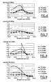
- Figures 6 to 9 show some results obtained, in the form of sensitivity curves representing variations in the sensitivity of a receiver depending on the chromatic dispersion and for different optical power values P of the transmitted signal.
- the dispersion chromatic is the so-called "residual" chromatic dispersion, i.e. the cumulative dispersion introduced by all constituent elements of the link, in particular fiber (s) transmission, dispersion compensation elements chromatic, including, where appropriate, corrective means (filters) according to the invention.
- the sensitivity which constitutes an evaluation of the quality of the transmission is defined here as the minimum value of the average optical power (in dBm) of signal to be applied to the receiver to obtain an error rate fixed at 10 -9 .
- the curves shown were obtained with connections with standard fibers of 100 km and for transmitted signals modulated in PSBT format at 10Gbit / s.
- the electro-optical modulator used is of the Mach-Zehnder type, controlled in "push-pull" mode by a filtered electrical signal by a Bessel filter with a bandwidth of 2.8 GHz.
- Figures 6 and 7 relate first to the case of a optical link consisting of a single 100 km section, such as illustrated in Figure 1.
- Figure 6 corresponds to a conventional system, that is to say without the FG filter.
- the Figure 7 corresponds to a system according to the invention, that is to say whose connection is coupled at output to the FG filter of spectral width at half height equal to 7.5 GHz or, expressed in wavelength, equal to 0.06 nm for a wavelength 1.55 ⁇ m carrier.
- Each of these figures shows three curves of sensitivity respectively for P powers of the signal supplied by the OA emission amplifier to the LF fiber from 0 dBm, 6 dBm and 12 dBm.
- Figures 8 and 9 relate to the case of a link optics consisting of three 100 km sections, such as illustrated in Figure 2.
- Figure 8 corresponds to a conventional system, i.e. without FG1 filters, FG2, FG3.
- Figure 9 corresponds to a system according to the invention, that is to say where each of the three sections is fitted with a filter FG1, FG2, FG3 of width spectral at half-height equal to 13 GHz or, expressed in wavelength, equal to 0.10 nm for a wavelength 1.55 ⁇ m carrier.
- Each of these figures shows four curves of sensitivity respectively for P powers of the signal applied to each LF1, LF2, LF3 fiber of 0 dBm, 6 dBm, 9 dBm and 12 dBm.
- the transmission system will then include elements of chromatic dispersion compensation DCF1, DCF2, DCF3 coupled respectively to sections L1, L2, L3, so that the cumulative chromatic dispersion introduced by these sections (L1, L2, L3), by the associated optical filters (FG1, FG2, FG3) and by the compensation elements of chromatic dispersion associated DCF1, DCF2, DCF3 or positive for the optical frequency f0 of the carrier wave optical of the phase-controlled optical signal S or, in the WDM multiplex transmission, for frequency mean optical wave carrier optical signals phase-controlled optics forming this multiplex.
- DCF1, DCF2, DCF3 coupled respectively to sections L1, L2, L3, so that the cumulative chromatic dispersion introduced by these sections (L1, L2, L3), by the associated optical filters (FG1, FG2, FG3) and by the compensation elements of chromatic dispersion associated DCF1, DCF2, DCF3 or positive for the optical frequency f0 of the carrier wave optical of the phase-controlled optical signal S or, in the WDM multiplex transmission,
Abstract
Description
L'invention se situe dans le domaine des systèmes optiques de télécommunication pour la transmission de données numériques. Elle concerne plus particulièrement les techniques de transmission de signaux optiques numériques à haut débit par des liaisons à longue distance utilisant des fibres optiques et/ou au travers de commutateurs optiques.The invention lies in the field of systems telecommunication optics for the transmission of digital data. It relates more particularly to techniques for transmitting digital optical signals to broadband by long distance links using fiber optics and / or through optical switches.
Un système optique de transmission comporte typiquement au moins un émetteur optique relié à un récepteur optique par l'intermédiaire d'une liaison optique qui peut être constituée d'une simple fibre ou de plusieurs tronçons de fibre reliés entre eux par des amplificateurs optiques et/ou des milieux de couplage plus complexes comportant par exemple des commutateurs réalisés au moyen de coupleurs, de guides et de portes optiques.An optical transmission system includes typically at least one optical transmitter connected to a optical receiver via an optical link which can consist of a single fiber or several fiber sections linked together by amplifiers optics and / or more complex coupling media comprising for example switches produced by means of couplers, guides and optical gates.
Un émetteur comporte une source de signal optique dont la fonction est d'appliquer à une onde porteuse optique une modulation fonction de l'information à émettre. Une même liaison peut véhiculer plusieurs signaux portés par des ondes porteuses de longueurs d'onde différentes. On réalise alors un système de transmission à multiplexage en longueur d'onde, dit "WDM" (de l'anglais "Wavelength Division Multiplexing").A transmitter includes an optical signal source of which the function is to apply an optical carrier wave modulation according to the information to be transmitted. The same link can carry several signals carried by carrier waves of different wavelengths. We realize then a length-division multiplex transmission system wave, known as "WDM" Multiplexing ").
Parmi les différentes techniques de modulation répertoriées, la plus couramment utilisée aujourd'hui est la modulation d'amplitude. Les formats de modulation généralement adoptés sont de type NRZ ou RZ. Ils consistent à coder des informations binaires par une variation de la puissance de l'onde porteuse entre deux niveaux : un niveau bas correspondant à une extinction de l'onde et un niveau haut correspondant à une puissance optique maximale. Ces variations de niveau sont déclenchées à des instants imposés par un rythme d'horloge de période fixe T qui définit ainsi des cellules temporelles successives allouées aux données binaires à transmettre. Par convention, les niveaux bas et hauts représentent habituellement les valeurs binaires "0" et "1" respectivement.Among the different modulation techniques listed, the most commonly used today is the amplitude modulation. Modulation formats generally adopted are NRZ or RZ type. They consist to encode binary information by varying the carrier wave power between two levels: one level low corresponding to an extinction of the wave and a level high corresponding to maximum optical power. These level variations are triggered at imposed times by a clock rhythm of fixed period T which thus defines successive time cells allocated to the data binaries to transmit. By convention, low levels and highs usually represent binary values "0" and "1" respectively.
La technique de modulation d'amplitude, souvent désignée par "ASK" (de l'anglais "Amplitude-Shift Keying"), présente l'avantage d'une mise en oeuvre relativement facile au moyen de composants optiques éprouvés, mais elle présente toutefois l'inconvénient d'être sensible à la dispersion chromatique. Bien qu'il existe des dispositifs de compensation de la dispersion chromatique, tels que les fibres dites "DCF" (de l'anglais "Dispersion compensating Fiber"), les compensations obtenues sont souvent imparfaites, en particulier lorsqu'il s'agit de compenser des canaux WDM répartis sur une large bande spectrale.Amplitude modulation technique, often designated by "ASK" (from the English "Amplitude-Shift Keying"), has the advantage of a relatively easy implementation using proven optical components, but it has however the disadvantage of being sensitive to dispersion chromatic. Although there are compensation for chromatic dispersion, such as so-called "DCF" fibers Fiber "), the compensations obtained are often imperfect, especially when it comes to compensating WDM channels distributed over a wide spectral band.
C'est pourquoi il a été proposé un nouveau format de modulation moins sensible à la dispersion chromatique. Le procédé de transmission optique appliquant ce format, appelé "Transmission Binaire à Profil de Phase Contrôlé" ou PSBT (de l'anglais : "Phase-Shaped Binary Transmission"), est notamment décrit dans la demande de brevet européen EP-A-0 792 036, déposée le 17 février 1997, publiée le 27 août 1997 et correspondant au brevet américain US-A-5 920 416, délivré le 6 juillet 1999.This is why a new format has been proposed. modulation less sensitive to chromatic dispersion. The optical transmission process using this format, called "Binary Transmission with Controlled Phase Profile" or PSBT (from English: "Phase-Shaped Binary Transmission"), is in particular described in the European patent application EP-A-0 792 036, filed on February 17, 1997, published on February 27 August 1997 and corresponding to the American patent US-A-5,920,416, issued July 6, 1999.
Selon ce procédé, à l'émission on applique à une onde porteuse un décalage de phase optique de l'ordre de 180° en valeur absolue à l'intérieur de chaque cellule qui correspond à un "0" logique et qui précède ou succède à toute cellule contenant un "1" logique. En réception, on peut convertir le signal optique reçu en signal électrique de la même façon que pour signal modulé au format NRZ, c'est-à-dire au moyen d'un simple photodétecteur.According to this process, on emission, a wave is applied carries an optical phase shift of the order of 180 ° in absolute value inside each cell which corresponds to a logical "0" which precedes or succeeds any cell containing a logical "1". In reception, we can convert the received optical signal into an electrical signal in the same way as for modulated signal in NRZ format, that is to say by means of a simple photodetector.
En plus d'améliorer la résistance à la dispersion chromatique, la modulation PSBT présente aussi la propriété que le spectre du signal qui en résulte est deux fois moins large que celui de la modulation NRZ, ce qui est avantageux pour les transmissions WDM dites denses, c'est-à-dire dont l'intervalle spectral entre canaux WDM est faible. In addition to improving the resistance to dispersion chromatic, PSBT modulation also has the property that the resulting signal spectrum is two times less wider than NRZ modulation, which is advantageous for so-called dense WDM transmissions, that is to say of which the spectral interval between WDM channels is small.
La modulation PSBT trouve toutefois ses limites dès lors que des phénomènes optiques non linéaires deviennent importants. C'est le cas par exemple lorsqu'on augmente la puissance optique du signal en vue d'augmenter les distances de transmission. On observe alors que pour une valeur de la dispersion chromatique cumulée de la liaison la qualité du signal reçu subit une dégradation qui dépend fortement de la longueur d'onde de la porteuse optique du signal. Le système devient donc moins tolérant à la dispersion chromatique, ce qui limite les possibilités de transmettre des signaux WDM répartis sur une large bande spectrale, sur de longues distance et sans amplifications intermédiaires.PSBT modulation finds its limits, however when nonlinear optical phenomena become important. This is the case for example when increasing the optical signal strength to increase distances of transmission. We then observe that for a value of the cumulative chromatic dispersion of the link the quality of received signal undergoes degradation which strongly depends on the wavelength of the optical signal carrier. The system therefore becomes less tolerant of chromatic dispersion, this which limits the possibilities of transmitting WDM signals distributed over a wide spectral band, over long distance and without intermediate amplifications.
Un autre cas où le problème se pose est celui où la transmission s'effectue par l'intermédiaire de milieux de couplage optique comportant des composants non linéaires même à faible puissance, comme par exemple des portes optiques à base d'amplificateurs optiques semi-conducteurs. Ce dernier cas se rencontre typiquement dans les réseaux équipés de commutateurs utilisant de telles portes optiques.Another case where the problem arises is where the transmission takes place through optical coupling with non-linear components even at low power, such as doors optics based on semiconductor optical amplifiers. The latter case is typically encountered in networks fitted with switches using such optical doors.
Une solution à ce problème de dégradation du signal PSBT dû à l'effet Kerr (automodulation de phase, modulation croisée de phase ou de gain) a été proposée dans la demande de brevet européen EP-A-0 975 107, déposée le 20 juillet 1998 et publiée le 26 janvier 2000. La solution consiste à utiliser une modulation PSBT modifiée pour introduire un "chirp" transitoire dont le signe et la valeur optimale dépendent notamment de la dispersion cumulée dans la liaison et des effets non linéaires. Toutefois, l'introduction d'un "chirp" transitoire optimal n'est pas facile à déterminer et il a en outre pour effet d'élargir le spectre du signal optique, ce qui rend la modulation PSBT moins avantageuse pour les transmissions WDM denses.A solution to this signal degradation problem PSBT due to the Kerr effect (phase self-modulation, modulation phase or gain crossover) was proposed in the request of European patent EP-A-0 975 107, filed on July 20 1998 and published on January 26, 2000. The solution is to use a modified PSBT modulation to introduce a transient "chirp" whose sign and optimal value depend in particular on the cumulative dispersion in the connection and non-linear effects. However, the introduction of a optimal transient "chirp" is not easy to determine and it also has the effect of broadening the signal spectrum optical, which makes PSBT modulation less advantageous for dense WDM transmissions.
Pour échapper en partie aux phénomènes non linéaires, une autre approche consiste à choisir des techniques de modulation qui conservent constante la puissance optique du signal. C'est le cas des modulations de fréquence ou de phase optique. La modulation de fréquence optique ou "FSK" (de l'anglais "Frequency-Shift Keying") présente toutefois l'inconvénient que le signal en résultant est sensible à la dispersion chromatique. La modulation de phase optique ou "PSK" (de l'anglais "Phase-Shift Keying") est moins sensible à la dispersion chromatique mais impose une parfaite stabilité de la phase du signal pour permettre une bonne détection au niveau des récepteurs. Par contre, une variante appelée modulation de phase optique différentielle ou "DPSK" (de l'anglais "Differential Phase-Shift Keying") a l'avantage de réduire cette dernière contrainte. Cependant, les modulations PSK ou DPSK entraínent une largeur spectrale du signal qui est la même qu'avec le format de modulation NRZ, donc moins favorable que la modulation PSBT pour les transmissions WDM denses .To partially escape non-linear phenomena, another approach is to choose modulation which keep the optical power of the signal. This is the case with frequency or optical phase. Optical frequency modulation or "FSK" (from the English "Frequency-Shift Keying") presents however the downside that the resulting signal is sensitive to the chromatic dispersion. Optical phase modulation or "PSK" (from the English "Phase-Shift Keying") is less sensitive chromatic dispersion but imposes a perfect signal phase stability to allow good detection at the receptor level. However, a variant called differential optical phase modulation or "DPSK" (from the English "Differential Phase-Shift Keying") a the advantage of reducing this last constraint. However, PSK or DPSK modulations entail a spectral width of the signal which is the same as with the modulation format NRZ, therefore less favorable than PSBT modulation for dense WDM transmissions.
Aussi l'invention a pour but de proposer un système de transmission utilisant la modulation PSBT sans chirp transitoire, mais adapté pour rendre le signal transmis moins sensible à la fois à la dispersion chromatique et à l'effet Kerr et plus spécifiquement à l'automodulation de phase.The object of the invention is therefore to propose a system of transmission using PSBT modulation without chirp transient, but suitable for rendering the transmitted signal less sensitive to both chromatic dispersion and the Kerr effect and more specifically the self-modulation of phase.
Plus précisément l'invention a pour objet un système de transmission pour signal optique à phase contrôlée, ce signal étant modulé au rythme d'une horloge de période T qui définit des cellules temporelles successives délimitant dans le signal des niveaux bas ou des niveaux hauts de modulation d'une onde porteuse optique de fréquence optique f0, ledit signal présentant un décalage de phase optique à l'intérieur de chaque cellule temporelle qui délimite un niveau bas de puissance et qui précède ou succède à une cellule qui délimite un niveau haut de puissance, ledit système comportant une liaison optique apte à transmettre ledit signal à phase contrôlée depuis une extrémité d'entrée jusqu'à une extrémité de sortie pour y fournir un signal de sortie correspondant, ledit système étant caractérisé en ce qu'il comporte des moyens optiques correcteurs couplés à ladite extrémité de sortie et/ou inséré en un ou plusieurs points de ladite liaison optique, ces moyens correcteurs appliquant un filtrage optique au signal présent à ladite extrémité de sortie et/ou auxdits points de ladite liaison optique, ce filtrage étant calibré de façon à compenser un élargissement de spectre que ledit signal à phase contrôlée peut subir par automodulation de phase au cours de sa transmission dans ladite liaison optique.More specifically, the subject of the invention is a system transmission for phase-controlled optical signal, this signal being modulated to the rhythm of a clock of period T which defines successive time cells delimiting in the signal of low levels or high levels of modulation an optical carrier wave of optical frequency f0, said signal with internal optical phase shift of each time cell that delimits a low level of power and which precedes or succeeds a cell which defines a high level of power, said system comprising an optical link capable of transmitting said phase controlled signal from an input end to an output end to provide a signal corresponding output, said system being characterized in that that it includes corrective optical means coupled to said outlet end and / or inserted in one or more points of said optical link, these correcting means applying optical filtering to the signal present at said outlet end and / or at said points of said link optical, this filtering being calibrated so as to compensate for a broadening of spectrum as said phase controlled signal can undergo by phase self-modulation during its transmission in said optical link.
L'invention prend en compte l'observation qu'un signal au format de modulation PSBT transmis dans un milieu non linéaire subit par automodulation de phase un élargissement de son spectre au fur et à mesure de sa propagation dans ce milieu et que l'application d'un filtrage optique conçu pour rétablir la largeur de spectre du signal transmis à celle du signal PSBT initial permet d'améliorer la qualité du signal.The invention takes into account the observation that a signal in PSBT modulation format transmitted in a non-medium linear undergoes an enlargement by phase of its spectrum as it propagates in this medium and that applying optical filtering designed to restore the spectrum width of the transmitted signal to that of the initial PSBT signal improves the signal quality.
Ainsi, la fonction de transfert de filtrage est calibrée pour produire une diminution de largeur de spectre suffisante pour éliminer une partie des composantes spectrales créées par l'automodulation de phase, sans toutefois atténuer exagérément la partie centrale du spectre car il en résulterait une perte d'information contenue dans le signal, ce qui serait contraire au but recherché. D'une façon générale, le choix du filtrage peut être considéré comme un compromis entre la compensation de l'élargissement du spectre et la perte d'information qui en résulte.So the filter transfer function is calibrated to produce a decrease in spectrum width sufficient to eliminate part of the components spectral created by phase self-modulation, without however excessively attenuate the central part of the spectrum as this would result in a loss of information contained in the signal, which would be contrary to the desired goal. On the one in general, the choice of filtering can be considered as a compromise between compensation for enlargement of the spectrum and the resulting loss of information.
Des simulations pour plusieurs cas particuliers, suivies de vérifications expérimentales ont permis de trouver un gabarit de filtrage pouvant convenir en pratique pour les cas usuels. Par ailleurs, il a été constaté que la compensation de l'élargissement de spectre est d'autant plus bénéfique que le filtrage est réparti le long de la liaison, en aval des éléments qui sont le siège de phénomènes non linéaires. Cette observation conduit en particulier à des mises en oeuvre du filtrage différentes selon que la liaison est constituée d'un seul ou de plusieurs tronçons. Simulations for several special cases, followed by experimental verifications allowed find a filtering template that can be used in practice for usual cases. Furthermore, it was found that the spectrum widening compensation is all the more beneficial that the filtering is distributed along the link, downstream of the elements which are the seat of phenomena not linear. This observation leads in particular to different filtering implementations depending on whether the link consists of one or more sections.
Plus précisément, selon un premier mode de réalisation de l'invention adapté au cas où la liaison comporte un seul tronçon muni d'une fibre de transmission, lesdits moyens optiques correcteurs sont constitués d'un filtre optique couplé à ladite extrémité de sortie et ayant une fonction de transfert, exprimant les variations en fonction de la fréquence optique f de son coefficient de transmission, approximativement gaussienne au voisinage de f0, centrée sur f0, avec une largeur spectrale à mi-hauteur comprise entre 0,5/T et 1,25/T, et avantageusement sensiblement égale à 0,75/T.More specifically, according to a first embodiment of the invention adapted to the case where the connection comprises a single section provided with a transmission fiber, said means corrective optics consist of an optical filter coupled to said outlet end and having a function of transfer, expressing the variations according to the optical frequency f of its transmission coefficient, approximately Gaussian in the vicinity of f0, centered on f0, with a half-height spectral width between 0.5 / T and 1.25 / T, and advantageously substantially equal to 0.75 / T.
Selon un second mode de réalisation de l'invention adapté au cas où la liaison comporte N tronçons ayant respectivement N extrémités d'entrée et N extrémités de sortie et munis respectivement de N amplificateurs optiques suivis respectivement de N fibres de transmission, lesdits moyens optiques correcteurs sont constitués de N filtres optiques couplés respectivement auxdites N extrémités de sortie desdits tronçons et tels que la fonction de transfert d'un filtre équivalent formé par le couplage en cascade desdits N filtres, exprimant les variations en fonction de la fréquence optique f de son coefficient de transmission, soit approximativement gaussienne au voisinage de f0, centrée sur f0, avec une largeur spectrale à mi-hauteur comprise entre 0,5/T et 1,25/T, et avantageusement sensiblement égale à 0,75/T.According to a second embodiment of the invention adapted to the case where the link comprises N sections having respectively N entry ends and N ends of output and respectively equipped with N optical amplifiers followed respectively by N transmission fibers, said fibers corrective optical means consist of N filters optics respectively coupled to said N ends of output of said sections and such as the transfer function an equivalent filter formed by the cascade coupling said N filters, expressing the variations as a function of the optical frequency f of its transmission coefficient, either approximately Gaussian in the vicinity of f0, centered on f0, with a spectral width at half height between 0.5 / T and 1.25 / T, and advantageously substantially equal to 0.75 / T.
Selon un autre aspect de réalisation de l'invention, quel que soit le type de liaison (un seul ou plusieurs tronçons), le ou chacun des filtres optiques (FG) sera un filtre périodique présentant un intervalle spectral libre exprimé en fréquences supérieur à 1/T.According to another aspect of the invention, whatever the type of connection (one or more sections), the or each of the optical filters (FG) will be a periodic filter with a free spectral range expressed in frequencies greater than 1 / T.
L'invention s'applique également aux systèmes de transmission optique pour signaux au format PSBT multiplexés en longueur d'onde. Un tel système est donc prévu pour transmettre un multiplex formé de plusieurs signaux optiques à phase contrôlée portés respectivement par plusieurs ondes porteuses optiques de fréquences optiques successives présentant un décalage fréquentiel donné. Dans ce cas et selon un autre aspect de réalisation de l'invention, le ou chacun des filtres optiques sera avantageusement un filtre périodique présentant un intervalle spectral libre exprimé en fréquences égal audit décalage fréquentiel. Grâce à cette disposition il suffit d'un seul filtre pour traiter simultanément les différents signaux formant le multiplex.The invention also applies to optical transmission for multiplexed PSBT format signals in wavelength. Such a system is therefore provided for transmit a multiplex formed by several optical signals with controlled phase carried respectively by several waves optical carriers of successive optical frequencies with a given frequency offset. In this case and according to another aspect of the invention, the or each of the optical filters will advantageously be a filter periodic with a free spectral range expressed in frequencies equal to said frequency offset. Thanks to that layout it only takes one filter to process simultaneously the different signals forming the multiplex.
D'autres aspects et avantages de l'invention apparaítront dans la suite de la description en référence aux figures.
- La figure 1 représente schématiquement un système de transmission selon l'invention, dans le cas d'une liaison optique constituée d'un seul tronçon.
- La figure 2 représente schématiquement un système de
transmission selon l'invention, dans le cas d'une liaison
optique constituée de plusieurs tronçons.
- La figure 3 représente schématiquement des spectres de signaux modulés au format PSBT émis et reçus dans le cas d'un système de transmission conventionnel.
- La figure 4 représente une fonction de transfert de filtre utilisable dans un système de transmission selon l'invention.
- La figure 5 représente une fonction de transfert de filtre périodique utilisable dans un système de transmission WDM selon l'invention.
- Les figures 6 et 7 représentent pour différentes valeurs de puissance optique de signal les variations de la sensibilité d'un récepteur en fonction de la dispersion chromatique, pour des systèmes de transmission respectivement conventionnel et selon l'invention, dans le cas d'une liaison optique constituée d'un seul tronçon.
- Les figures 8 et 9 représentent pour différentes valeurs de puissance optique de signal les variations de la sensibilité d'un récepteur en fonction de la dispersion chromatique, pour des systèmes de transmission respectivement conventionnel et selon l'invention, dans le cas d'une liaison optique constituée de trois tronçons.
- Figure 1 shows schematically a transmission system according to the invention, in the case of an optical link consisting of a single section.
- FIG. 2 schematically represents a transmission system according to the invention, in the case of an optical link made up of several sections.
- FIG. 3 schematically represents spectra of signals modulated in PSBT format transmitted and received in the case of a conventional transmission system.
- FIG. 4 represents a filter transfer function usable in a transmission system according to the invention.
- FIG. 5 represents a periodic filter transfer function usable in a WDM transmission system according to the invention.
- FIGS. 6 and 7 show, for different values of optical signal power, the variations in the sensitivity of a receiver as a function of chromatic dispersion, for respectively conventional transmission systems and according to the invention, in the case of a link. optics consisting of a single section.
- FIGS. 8 and 9 show, for different optical signal power values, the variations in the sensitivity of a receiver as a function of the chromatic dispersion, for respectively conventional transmission systems and according to the invention, in the case of a link. optic made up of three sections.
Les figures 1 et 2 montrent schématiquement et à titre d'exemple deux systèmes de transmission optique selon l'invention.Figures 1 and 2 show schematically and by way of example two optical transmission systems according to the invention.
Dans le cas de la figure 1, le système comporte une liaison optique L composée d'un seul tronçon et disposée entre un émetteur TX et un récepteur RX. En fonction d'un signal source, par exemple un signal électrique E modulé au format NRZ au rythme d'une horloge de période T, l'émetteur TX est apte à délivrer un signal optique à phase contrôlée S modulé au même rythme d'horloge au format PSBT, tel qu'exposé en détails dans les documents précités. Le récepteur RX comporte essentiellement un préamplificateur optique suivi d'un photodétecteur.In the case of FIG. 1, the system comprises a optical link L composed of a single section and arranged between a TX transmitter and an RX receiver. Based on a source signal, for example an electrical signal E modulated at NRZ format to the rhythm of a clock of period T, the transmitter TX is able to deliver an optical signal with controlled phase S modulated at the same clock rate in PSBT format, such that detailed in the aforementioned documents. The RX receiver basically has a preamplifier optics followed by a photodetector.
La liaison L comporte une extrémité d'entrée A prévue pour recevoir le signal S et une extrémité de sortie B, située au voisinage du récepteur RX et prévue pour délivrer un signal de sortie correspondant R. La liaison L est constituée principalement d'une fibre de transmission LF et d'un amplificateur optique d'émission OA disposé entre l'émetteur TX et la fibre LF. Pour améliorer le rapport signal à bruit en réception, un préamplificateur optique de réception OA' peut en outre être prévu en aval de la fibre LF.Connection L has an inlet end A provided to receive the signal S and an output end B, located near the RX receiver and designed to deliver a corresponding output signal R. The link L is mainly consisting of an LF transmission fiber and an optical emission amplifier OA disposed between TX transmitter and LF fiber. To improve the report signal to noise reception, an optical preamplifier OA 'reception can also be provided downstream of the fiber LF.
Dans un système conventionnel, le signal de sortie R serait couplé directement au récepteur RX, ou éventuellement par l'intermédiaire d'un élément de compensation de dispersion chromatique DCF. Un filtre passe-bande centrée sur la fréquence d'une onde porteuse de signal peut aussi être prévu en amont du récepteur, par exemple pour extraire un canal dans le cas d'une transmission WDM ou pour atténuer du bruit présent en dehors de la bande du signal. Dans ce cas, le coefficient de transmission du filtre en fonction de la fréquence optique a toujours une largeur spectrale très supérieure à la fréquence d'horloge 1/T de modulation du signal.In a conventional system, the output signal R would be coupled directly to the RX receiver, or possibly through a compensation element of DCF chromatic dispersion. A centered bandpass filter on the frequency of a signal carrier wave can also be provided upstream of the receiver, for example to extract a channel in the case of a WDM transmission or to attenuate noise outside the signal band. In this case, the transmission coefficient of the filter as a function of the optical frequency always has a very wide spectral width higher than the 1 / T clock frequency of modulation of signal.
Pour pouvoir augmenter la distance de transmission au moyen d'un seul tronçon, on doit augmenter la longueur de la fibre LF mais aussi compenser l'augmentation d'atténuation qui en résulte en augmentant la puissance optique du signal injecté dans la fibre LF. Au delà d'une certaine puissance, la fibre est le siège de phénomènes optiques non linéaires (effet Kerr) importants.To be able to increase the transmission distance to by means of a single section, the length of the LF fiber but also compensate for the increase in attenuation which results in increasing the optical power of the signal injected into the LF fiber. Beyond a certain power, fiber is the seat of nonlinear optical phenomena (Kerr effect) important.
En particulier, dans le cas d'un signal modulé au format PSBT, qui en l'absence d'effets non linéaires est peu sensible à la dispersion chromatique, on observe une moindre tolérance à la dispersion chromatique cumulée dans la liaison. Il en résulte une limitation de capacité de transmission, par exemple dans le cas de signaux WDM.In particular, in the case of a signal modulated at PSBT format, which in the absence of non-linear effects is little sensitive to chromatic dispersion, there is less tolerance to the cumulative chromatic dispersion in the link. This results in a capacity limitation of transmission, for example in the case of WDM signals.
En analysant plus en détail ce phénomène, il a pu être constaté que cette dégradation est corrélée à un élargissement du spectre du signal au fur et à mesure de sa propagation dans la fibre. Ceci est illustré par la figure 3.By analyzing this phenomenon in more detail, it could be found that this degradation is correlated with a widening of the signal spectrum as it progresses propagation in the fiber. This is illustrated by the figure 3.
La figure 3 montre en trait plein une courbe approximative du spectre du signal émis S modulé au format PSBT. Ce spectre qui exprime les variations de la densité spectrale de puissance normalisée FT2 (S) en fonction de la fréquence optique f correspond à un signal PSBT de fréquence porteuse optique f0 et de période bit T. La figure 3 montre aussi en tirets la courbe FT2 (R) représentative du spectre du signal reçu R dans le cas d'une liaison conventionnelle. Le spectre du signal subit donc au cours de sa transmission dans la liaison un élargissement qui est attribué principalement à une automodulation de phase du signal.FIG. 3 shows in solid lines an approximate curve of the spectrum of the transmitted signal S modulated in PSBT format. This spectrum which expresses the variations of the normalized power spectral density FT 2 (S) as a function of the optical frequency f corresponds to a signal PSBT of optical carrier frequency f0 and of bit period T. FIG. 3 also shows the curve FT 2 (R) representative of the spectrum of the received signal R in the case of a conventional link. The spectrum of the signal therefore undergoes a broadening during its transmission in the link, which is mainly attributed to a phase self-modulation of the signal.
Selon l'invention, un filtre optique FG est couplé à l'extrémité de sortie B de façon à se trouver inséré entre cette extrémité B et le récepteur RX. Le filtre est calibré pour appliquer au signal R une diminution de largeur de son spectre de façon à compenser, voire surcompenser, l'élargissement produit dans la fibre.According to the invention, an FG optical filter is coupled to the outlet end B so as to be inserted between this end B and the RX receiver. The filter is calibrated to apply a reduction in sound width to signal R spectrum so as to compensate, even overcompensate, the enlargement produced in the fiber.
Des simulations et des expérimentations permettent pour chaque cas particulier de liaison de trouver un gabarit de filtrage idéal adapté. Les filtres pouvant convenir en pratique sont typiquement de type gaussien (ou approchant) et ayant une fonction de transfert (qui exprime les variations du coefficient de transmission du filtre en fonction de la fréquence optique f) centrée sur f0 et de largeur spectrale à mi-hauteur comprise entre 0,5/T et 1,25/T.Simulations and experiments allow to find a template for each particular connection case ideal filtering solution. Filters may be suitable for practice are typically of the Gaussian (or approaching) type and having a transfer function (which expresses variations in the filter transmission coefficient in function of the optical frequency f) centered on f0 and of spectral width at mid-height between 0.5 / T and 1.25 / T.
De préférence, cette largeur spectrale à mi-hauteur est voisine de 0,75/T.Preferably, this spectral width at mid-height is close to 0.75 / T.
La figure 4 montre une courbe représentative de la
fonction de transfert normalisée G(f) correspondant à ce
dernier cas. On peut aussi exprimer cette fonction de
transfert par :
Dans d'autres systèmes de transmission, la liaison est constituée de plusieurs tronçons. A titre d'exemple, le cas d'une liaison à trois tronçons est représenté par la figure 2.In other transmission systems, the link is consisting of several sections. For example, the case of a link with three sections is represented by the figure 2.
Les études ayant montré qu'il est préférable de répartir le filtrage le long de la liaison, la mise en oeuvre du filtrage dans le cas d'une liaison à plusieurs tronçons conduit à une solution différente du premier cas exposé ci-dessus.Studies that have shown that it is better to distribute the filtering along the link, the implementation filtering in the case of a link with several sections leads to a different solution from the first case described above.
Comme le montre la figure 2, la liaison est composée d'une succession de tronçons L1, L2, L3. Chaque tronçon a une constitution identique à la liaison L de figure 1. On retrouve pour chaque tronçon L1-L3 une extrémité d'entrée A1-A3 et une extrémité de sortie B1-B3, un amplificateur optique d'émission OA1-OA3 suivi d'une fibre de transmission LF1-LF3, d'un préamplificateur optique de réception OA'1-OA'3 et d'un élément de compensation de dispersion chromatique DCF1-DCF3. L'extrémité d'entrée A1 du premier tronçon L1 est prévue pour recevoir de l'émetteur TX (non représenté) le signal S, tandis que l'extrémité de sortie B3 du dernier tronçon L3 est située au voisinage du récepteur RX et prévue pour délivrer un signal de sortie correspondant R.As shown in Figure 2, the link is composed of a succession of sections L1, L2, L3. Each section has a constitution identical to the bond L of figure 1. We finds for each section L1-L3 an inlet end A1-A3 and one output end B1-B3, an amplifier OA1-OA3 emission optics followed by a transmission fiber LF1-LF3, of an optical reception preamplifier OA'1-OA'3 and a dispersion compensation element chromatic DCF1-DCF3. The entry end A1 of the first section L1 is intended to receive from the transmitter TX (not shown) signal S, while output end B3 of the last section L3 is located near the receiver RX and designed to deliver a corresponding output signal R.
Selon l'invention, les moyens optiques correcteurs sont constitués de plusieurs filtres optiques FG1, FG2, FG3 couplés respectivement aux extrémités de sortie B1, B2, B3 des tronçons de façon à se trouver insérés respectivement entre ces extrémités de sortie B1, B2 et les extrémités d'entrée A2, A3 des tronçons suivants, à l'exception du dernier filtre qui est inséré entre l'extrémités de sortie B3 du dernier tronçon et le récepteur RX.According to the invention, the corrective optical means consist of several optical filters FG1, FG2, FG3 coupled respectively to the output ends B1, B2, B3 sections so as to be inserted respectively between these outlet ends B1, B2 and the ends A2, A3 of the following sections, except for the last filter which is inserted between the output ends B3 of the last section and the RX receiver.
Comme précédemment, les simulations et les expérimentations permettent pour chaque cas particulier de liaison de trouver un gabarit de filtrage optimal adapté.As before, the simulations and experiments allow for each particular case to link to find a suitable optimal filtering template.
En pratique les filtres FG1, FG2, FG3 seront avantageusement choisis de sorte que la fonction de transfert du filtre équivalent qui serait formé par le couplage en cascade de ces filtres soit approximativement gaussienne au voisinage de f0, centrée sur f0, avec une largeur spectrale à mi-hauteur comprise entre 0,5/T et 1,25/T. De préférence, cette largeur spectrale à mi-hauteur est sensiblement égale à 0,75/T.In practice the filters FG1, FG2, FG3 will be advantageously chosen so that the function of transfer of the equivalent filter which would be formed by the cascade coupling of these filters is approximately Gaussian near f0, centered on f0, with a spectral width at mid-height between 0.5 / T and 1.25 / T. Preferably, this spectral width at mid-height is substantially equal to 0.75 / T.
Ainsi, dans le cas d'une liaison à N tronçons, en
prenant N filtres de Gauss identiques de fonction de
transfert Gi(f) = exp [-b2.(f-f0)2.T2], la fonction de
transfert équivalente pour ces N filtres en cascade sera :
On aura donc N.b2 = a2, ce qui implique pour chacun des filtres une largeur spectrale à mi-hauteur N fois plus grande que pour le filtre adapté au cas où la liaison comporte un seul tronçon. We will therefore have Nb 2 = a 2 , which implies for each of the filters a spectral width at half height N times greater than for the filter adapted to the case where the connection comprises a single section.
Quel que soit le type de liaison (un seul ou plusieurs tronçons), chacun des filtres optiques peut être un filtre périodique, tel qu'un filtre Fabry-Pérot, respectant les critères précédents, à condition que son intervalle spectral libre exprimé en fréquences soit supérieur à 1/T.Whatever the type of connection (one or more sections), each of the optical filters can be a filter periodic, such as a Fabry-Pérot filter, respecting the previous criteria, provided that its spectral range free expressed in frequencies is greater than 1 / T.
Les systèmes qui viennent d'être décrits sont aussi utilisables pour des transmissions WDM de signaux au format PSBT. L'émetteur TX peut alors comporter des moyens (non représentés) pour moduler et combiner plusieurs signaux au format PSBT portés respectivement par plusieurs ondes porteuses optiques de fréquences optiques différentes. Le récepteur RX comporte alors des moyens (non représentés) pour démultiplexer le signal reçu de façon à séparer ses différentes composantes spectral.The systems which have just been described are also usable for WDM transmissions of signals in format PSBT. The TX transmitter can then include means (not shown) to modulate and combine several signals at PSBT format carried respectively by several waves optical carriers of different optical frequencies. The RX receiver then includes means (not shown) to demultiplex the received signal so as to separate its different spectral components.
Dans ce cas, une façon particulièrement simple de mettre en oeuvre l'invention consiste à utiliser comme filtres optiques des filtres périodiques ayant un intervalle spectral libre ISL égal au décalage entre les fréquences optiques successives des ondes porteuses optiques du multiplex.In this case, a particularly simple way of implementing the invention consists in using as optical filters periodic filters with an interval ISL free spectrum equal to the offset between frequencies successive optical waves of the optical carrier multiplex.
Ce cas est schématisé à la figure 5 qui montre la fonction de transfert G(f) d'un filtre périodique adapté à une transmission multiplex de canaux portés par des ondes porteuses de fréquences optiques f0, f1, f2, f3, f4.This case is shown schematically in Figure 5 which shows the transfer function G (f) of a periodic filter adapted to multiplex transmission of channels carried by waves carriers of optical frequencies f0, f1, f2, f3, f4.
Pour apprécier l'efficacité de l'invention, la qualité des signaux reçus a été évaluée avec des systèmes de transmission conventionnels et avec ces mêmes systèmes munis des moyens optiques correcteurs selon l'invention.To assess the effectiveness of the invention, the quality received signals has been evaluated with conventional transmission and with these same systems fitted corrective optical means according to the invention.
Les figures 6 à 9 permettent d'exposer quelques résultats obtenus, sous la forme de courbes de sensibilité représentant les variations de la sensibilité d'un récepteur en fonction de la dispersion chromatique et pour différentes valeurs de puissance optique P du signal émis. La dispersion chromatique est la dispersion chromatique dite "résiduelle", c'est-à-dire la dispersion cumulée introduite par tous les éléments constitutifs de la liaison, notamment fibre(s) de transmission, éléments de compensation de dispersion chromatique, y compris le cas échéant les moyens correcteurs (filtres) selon l'invention.Figures 6 to 9 show some results obtained, in the form of sensitivity curves representing variations in the sensitivity of a receiver depending on the chromatic dispersion and for different optical power values P of the transmitted signal. The dispersion chromatic is the so-called "residual" chromatic dispersion, i.e. the cumulative dispersion introduced by all constituent elements of the link, in particular fiber (s) transmission, dispersion compensation elements chromatic, including, where appropriate, corrective means (filters) according to the invention.
La sensibilité qui constitue une évaluation de la qualité de la transmission est définie ici comme la valeur minimale de la puissance optique moyenne (en dBm) de signal à appliquer au récepteur pour obtenir un taux d'erreur fixé à 10-9.The sensitivity which constitutes an evaluation of the quality of the transmission is defined here as the minimum value of the average optical power (in dBm) of signal to be applied to the receiver to obtain an error rate fixed at 10 -9 .
Les courbes représentées ont été obtenues avec des liaisons munies de fibres standard de 100 km et pour des signaux émis modulés au format PSBT à 10Gbit/s. Le modulateur électro-optique utilisé est de type Mach-Zehnder, commandé en mode "push-pull" par un signal électrique filtré par un filtre de Bessel de bande passante de 2,8 GHz.The curves shown were obtained with connections with standard fibers of 100 km and for transmitted signals modulated in PSBT format at 10Gbit / s. The electro-optical modulator used is of the Mach-Zehnder type, controlled in "push-pull" mode by a filtered electrical signal by a Bessel filter with a bandwidth of 2.8 GHz.
Les figures 6 et 7 concernent d'abord le cas d'une liaison optique constituée d'un seul tronçon de 100 km, tel qu'illustré à la figure 1. La figure 6 correspond à un système conventionnel, c'est-à-dire démuni du filtre FG. La figure 7 correspond à un système selon l'invention, c'est-à-dire dont la liaison est couplée en sortie au filtre FG de largeur spectrale à mi-hauteur égale à 7,5 GHz ou , exprimée en longueur d'onde, égale à 0,06 nm pour une longueur d'onde porteuse de 1,55µm.Figures 6 and 7 relate first to the case of a optical link consisting of a single 100 km section, such as illustrated in Figure 1. Figure 6 corresponds to a conventional system, that is to say without the FG filter. The Figure 7 corresponds to a system according to the invention, that is to say whose connection is coupled at output to the FG filter of spectral width at half height equal to 7.5 GHz or, expressed in wavelength, equal to 0.06 nm for a wavelength 1.55 µm carrier.
Chacune de ces figures montre trois courbes de sensibilité respectivement pour des puissances P du signal fourni par l'amplificateur d'émission OA à la fibre LF de 0 dBm, 6 dBm et 12 dBm.Each of these figures shows three curves of sensitivity respectively for P powers of the signal supplied by the OA emission amplifier to the LF fiber from 0 dBm, 6 dBm and 12 dBm.
En observant d'abord les courbes de la figure 6, on remarque qu'au delà de 6 dBm le signal reçu subit une dégradation importante pour les valeurs de dispersion cumulée inférieures à +500 ps/nm. En d'autre termes, à forte puissance optique d'émission, le système n'est pas tolérant à la dispersion chromatique, ce qui limite les possibilités de transmettre des signaux WDM à large bande sur de longues distance et sans amplifications intermédiaires. By first observing the curves in Figure 6, we note that above 6 dBm the received signal undergoes a significant degradation for dispersion values cumulative less than +500 ps / nm. In other words, at high optical transmission power, the system is not tolerant chromatic dispersion, which limits the possibilities transmit broadband WDM signals over long distance and without intermediate amplifications.
En comparant ces courbes à celles de la figure 7, on constate que l'invention procure une forte amélioration de la tolérance à la dispersion chromatique, même pour les valeurs négatives de dispersion.By comparing these curves to those in Figure 7, we notes that the invention provides a great improvement in tolerance to chromatic dispersion, even for negative dispersion values.
Les figures 8 et 9 concernent le cas d'une liaison optique constituée de trois tronçons de 100 km, tel qu'illustré à la figure 2. La figure 8 correspond à un système conventionnel, c'est-à-dire démuni des filtres FG1, FG2, FG3. La figure 9 correspond à un système selon l'invention, c'est-à-dire où chacun des trois tronçons est muni en sortie d'un filtre FG1, FG2, FG3 de largeur spectrale à mi-hauteur égale à 13 GHz ou , exprimée en longueur d'onde, égale à 0,10 nm pour une longueur d'onde porteuse de 1,55µm.Figures 8 and 9 relate to the case of a link optics consisting of three 100 km sections, such as illustrated in Figure 2. Figure 8 corresponds to a conventional system, i.e. without FG1 filters, FG2, FG3. Figure 9 corresponds to a system according to the invention, that is to say where each of the three sections is fitted with a filter FG1, FG2, FG3 of width spectral at half-height equal to 13 GHz or, expressed in wavelength, equal to 0.10 nm for a wavelength 1.55 µm carrier.
Chacune de ces figures montre quatre courbes de sensibilité respectivement pour des puissances P du signal appliqué à chaque fibre LF1, LF2, LF3 de 0 dBm, 6 dBm ,9 dBm et 12 dBm.Each of these figures shows four curves of sensitivity respectively for P powers of the signal applied to each LF1, LF2, LF3 fiber of 0 dBm, 6 dBm, 9 dBm and 12 dBm.
En observant les courbes de la figure 8, on voit que pour les valeurs de dispersion cumulée inférieures à +500 ps/nm la dégradation du signal reçu devient importante à partir de 9 dBm et est très importante pour 12 dBm. En comparant ces courbes à celles de la figure 9, on peut constater l'amélioration obtenue grâce à l'invention.By observing the curves of figure 8, we see that for cumulative dispersion values less than +500 ps / nm the degradation of the received signal becomes significant at from 9 dBm and is very important for 12 dBm. In comparing these curves to those of figure 9, we can note the improvement obtained thanks to the invention.
Il est intéressant de noter que la présence du ou des filtres selon l'invention n'introduit pas de pénalité pour les faibles puissances.It is interesting to note that the presence of the filters according to the invention does not introduce a penalty for the low powers.
Ces courbes montrent aussi l'intérêt de disposer d'une liaison présentant une dispersion chromatique cumulée positive, ce qui implique généralement l'introduction de moyens de compensation de dispersion chromatique. Dans ce cas, il a été par ailleurs vérifié que ces moyens de compensation doivent de préférence être répartis sur les différents tronçons qui constituent la liaison.These curves also show the advantage of having a bond with cumulative chromatic dispersion positive, which usually involves the introduction of chromatic dispersion compensation means. In this case, it has also been verified that these means of compensation should preferably be spread over the different sections which constitute the connection.
Plus précisément, comme représenté à la figure 2, le système de transmission comportera alors des éléments de compensation de dispersion chromatique DCF1, DCF2, DCF3 couplés respectivement aux tronçons L1, L2, L3, de sorte que la dispersion chromatique cumulée introduite par ces tronçons (L1, L2, L3), par les filtres optiques associés (FG1, FG2, FG3) et par les éléments de compensation de dispersion chromatique associés DCF1, DCF2, DCF3 soit positive pour la fréquence optique f0 de l'onde porteuse optique du signal optique S à phase contrôlée ou, dans le cas d'une transmission de multiplex WDM, pour la fréquence optique moyenne des ondes porteuses optiques des signaux optiques à phase contrôlée formant ce multiplex.More specifically, as shown in Figure 2, the transmission system will then include elements of chromatic dispersion compensation DCF1, DCF2, DCF3 coupled respectively to sections L1, L2, L3, so that the cumulative chromatic dispersion introduced by these sections (L1, L2, L3), by the associated optical filters (FG1, FG2, FG3) and by the compensation elements of chromatic dispersion associated DCF1, DCF2, DCF3 or positive for the optical frequency f0 of the carrier wave optical of the phase-controlled optical signal S or, in the WDM multiplex transmission, for frequency mean optical wave carrier optical signals phase-controlled optics forming this multiplex.
Claims (10)
- A transmission system for transmitting controlled phase optical signals (S) modulated at the timing rate of a clock of period T which defines successive time cells defining in the signal (S) low levels or high levels of modulation of an optical carrier wave of optical frequency F0, said signal (S) having an optical phase shift in each time cell which defines a low power level and which precedes or follows a cell which defines a high power level, said system including an optical link (L) adapted to transmit said controlled phase signal (S) from an entry end (A, A1) to an exit end (B, B3), and said system being characterized in that it includes optical corrector means (FG, FG1, FG2, FG3) coupled to said exit end (B, B3) and/or inserted at one or more points (B1, B2) of said optical link (L), said corrector means applying optical filtering to the signal (R) at said exit end (B, B3) and/or at said points (B1, B2) of said optical link (L), said filtering being set to compensate widening of its spectrum that said controlled phase signal (S) might suffer because of phase self-modulation as it is transmitted in said optical link (L).
- A transmission system according to claim 1, characterized in that said link (L) includes a single section of line fiber (LF) and said optical corrector means comprise an optical filter (FG) coupled to said exit end (B) and having a transfer function (G(F)) expressing variations as a function of the optical frequency F of its transmission coefficient that is approximately Gaussian in the vicinity of F0, centered at F0, with a half-height spectral width from 0.5/T to 1.25/T.
- A transmission system according to claim 2, characterized in that said half-height spectral width is substantially equal to 0.75/T.
- A transmission system according to claim 2 or claim 3, characterized in that said optical filter (FG) is a periodic filter having a free spectral interval (ISL), when expressed in terms of frequency, greater than 1/T.
- A transmission system according to claim 4, characterized in that said system is adapted to transmit a wavelength division multiplex formed of a plurality of controlled phase optical signals carried by a plurality of respective optical carrier waves with successive optical frequencies (F0, F1, F2, F3) having a given frequency shift and said free spectral interval (ISL) is equal to said frequency shift.
- A transmission system according to claim 1, characterized in that said link comprises N sections (L1, L2, L3) having N respective entry ends (A1, A2, A3), N respective exit ends (B1, B2, B3), and N respective optical amplifiers (OA1, OA2, OA3) followed by N respective line fibers (LF1, LF2, LF3), said optical corrector means comprise N optical filters (FG1, FG2, FG3) respectively coupled to said N exit ends (B1, B2, B3) of said sections and such that the transfer function (G(F)) of the equivalent filter formed by coupling said N filters (FG1, FG2, FG3) in cascade, expressing variations of its transmission coefficient as a function of the optical frequency F, is approximately Gaussian in the vicinity of F0, centered at F0, with a half-height spectral width from 0.5/T to 1.25/T.
- A transmission system according to claim 6, characterized in that said half-height spectral width is substantially equal to 0.75/T.
- A transmission system according to claim 6 or claim 7, characterized in that each of said optical filters (FG1, FG2, FG3) is a periodic filter having a free spectral interval (ISL) greater than 1/T.
- A transmission system according to claim 8, characterized in that said system is adapted to transmit a wavelength division multiplex formed of a plurality of controlled phase optical signals carried by a plurality of respective optical carrier waves with successive optical frequencies (F0-F4) having a given frequency shift and said free spectral interval (ISL) is equal to said frequency shift.
- A transmission system according to any one of claims 6 to 9, characterized in that it includes respective chromatic dispersion compensators (DCF1, DCF2, DCF3) coupled to said N sections (L1, L2, L3) so that the cumulative chromatic dispersion introduced by said sections (L1, L2, L3), said associated optical filters (FG1, FG2, FG3), and said associated chromatic dispersion compensators (DCF1, DCF2, DCF3) is positive for the optical frequency (F0) of said optical carrier wave of said controlled phase optical signal (S) or where applicable for the average optical frequency of said optical carrier waves of said controlled phase optical signals forming said multiplex.
Applications Claiming Priority (2)
| Application Number | Priority Date | Filing Date | Title |
|---|---|---|---|
| FR0114604A FR2832228B1 (en) | 2001-11-12 | 2001-11-12 | OPTICAL TRANSMISSION SYSTEM |
| FR0114604 | 2001-11-12 |
Publications (2)
| Publication Number | Publication Date |
|---|---|
| EP1311079A1 EP1311079A1 (en) | 2003-05-14 |
| EP1311079B1 true EP1311079B1 (en) | 2004-10-13 |
Family
ID=8869301
Family Applications (1)
| Application Number | Title | Priority Date | Filing Date |
|---|---|---|---|
| EP02292723A Expired - Lifetime EP1311079B1 (en) | 2001-11-12 | 2002-10-31 | Phase controlled optical signal transmission system |
Country Status (6)
| Country | Link |
|---|---|
| US (1) | US7123841B2 (en) |
| EP (1) | EP1311079B1 (en) |
| CN (1) | CN1419348A (en) |
| AT (1) | ATE279820T1 (en) |
| DE (1) | DE60201569T2 (en) |
| FR (1) | FR2832228B1 (en) |
Families Citing this family (3)
| Publication number | Priority date | Publication date | Assignee | Title |
|---|---|---|---|---|
| ATE338391T1 (en) * | 2000-10-27 | 2006-09-15 | Cit Alcatel | SYSTEM AND DEVICE FOR TRANSMITTING OPTICAL DATA |
| US8238757B2 (en) * | 2007-01-18 | 2012-08-07 | Futurewei Technologies, Inc. | Method and apparatus for generating optical duobinary signals with enhanced receiver sensitivity and spectral efficiency |
| WO2009113355A1 (en) * | 2008-03-10 | 2009-09-17 | 住友電気工業株式会社 | Optical communication system |
Family Cites Families (5)
| Publication number | Priority date | Publication date | Assignee | Title |
|---|---|---|---|---|
| FR2707442B1 (en) * | 1993-07-06 | 1995-09-15 | Pirio Francis | Transmission system on optical fiber with compensation for online distortions. |
| FR2745451B1 (en) * | 1996-02-23 | 1998-04-17 | Cit Alcatel | METHOD FOR OPTICAL TRANSMISSION OF DIGITAL DATA |
| FR2781322B1 (en) * | 1998-07-20 | 2000-09-08 | Alsthom Cge Alcatel | OPTICAL DATA TRANSMISSION DEVICE |
| US6430336B1 (en) * | 2000-12-18 | 2002-08-06 | Ciena Corporation | Device and method for minimizing optical channel drift |
| US6522450B2 (en) * | 2001-04-25 | 2003-02-18 | Corning Incorporated | Loss-less tunable per-channel dispersion compensator |
-
2001
- 2001-11-12 FR FR0114604A patent/FR2832228B1/en not_active Expired - Fee Related
-
2002
- 2002-10-31 EP EP02292723A patent/EP1311079B1/en not_active Expired - Lifetime
- 2002-10-31 AT AT02292723T patent/ATE279820T1/en not_active IP Right Cessation
- 2002-10-31 DE DE60201569T patent/DE60201569T2/en not_active Expired - Fee Related
- 2002-11-04 US US10/286,827 patent/US7123841B2/en not_active Expired - Fee Related
- 2002-11-11 CN CN02150525A patent/CN1419348A/en active Pending
Also Published As
| Publication number | Publication date |
|---|---|
| DE60201569D1 (en) | 2004-11-18 |
| DE60201569T2 (en) | 2005-12-22 |
| ATE279820T1 (en) | 2004-10-15 |
| US20030090770A1 (en) | 2003-05-15 |
| US7123841B2 (en) | 2006-10-17 |
| FR2832228A1 (en) | 2003-05-16 |
| FR2832228B1 (en) | 2004-11-19 |
| CN1419348A (en) | 2003-05-21 |
| EP1311079A1 (en) | 2003-05-14 |
Similar Documents
| Publication | Publication Date | Title |
|---|---|---|
| CA2165689C (en) | Method for low sensitivity optical transmission, transmission device and system for carrying out said method | |
| EP0975107B1 (en) | Transmitting device for optical data | |
| FR2737630A1 (en) | WAVELENGTH MULTIPLEXING OPTICAL TRANSMISSION SYSTEM AND TRANSMISSION DEVICE USED IN THIS TRANSMISSION SYSTEM | |
| EP0862286B1 (en) | Optical regeneration for optical fibre transmission systems with non-soliton signals | |
| FR2685835A1 (en) | VERY LONG DISTANCE TRANSMISSION SYSTEM ON OPTICAL FIBER COMPENSATED FOR DISTORTIONS AT RECEPTION. | |
| US20060013596A1 (en) | Bandwidth limited frequency shift keying modulation format | |
| FR2707442A1 (en) | Optical fiber transmission system with on-line distortion compensation. | |
| JPH11239099A (en) | Optical communication system using synchronous polarization scrambler and optical receiver | |
| FR2773620A1 (en) | Optical telecommunications terminal station | |
| JP3837358B2 (en) | Optical communication system | |
| EP0744844B1 (en) | Method of inscription of binary data on a carrier wave, especially optical, and transmission system using this method | |
| US8208816B2 (en) | Method and apparatus for dispersion mitigation in optical links | |
| EP1311079B1 (en) | Phase controlled optical signal transmission system | |
| EP0883256B1 (en) | Soliton WDM optical fibre transmission system with saturable absorbers | |
| EP0818896A1 (en) | Optical data transmission system in soliton format | |
| EP1111819B1 (en) | Fiber optic transmission system with noise reduction using a non linear offset of the signals | |
| EP1228589B1 (en) | Optical fibre transmission system using rz pulses | |
| EP0746070B1 (en) | Method and device to combine optical signals | |
| EP0994585B1 (en) | Power equalisation in a WDM optical transmission system comprising several amplifiers | |
| WO2002019574A1 (en) | All-optical regenerator for wavelength-division multiplexed signals | |
| EP0941587A1 (en) | Optical transmission system with coherent optical time domain reflectometry | |
| EP1286483A2 (en) | Improved optical modulator allowing an optimization of NRZ-modulation | |
| EP0994584A1 (en) | Repeater for a long-haul optical fiber transmission system using WDM | |
| Lyubomirsky et al. | Experimental demonstration of a theoretically optimum optical duobinary transmission system | |
| EP1021004A1 (en) | Method and apparatus for the stabilization of optical solitons |
Legal Events
| Date | Code | Title | Description |
|---|---|---|---|
| PUAI | Public reference made under article 153(3) epc to a published international application that has entered the european phase |
Free format text: ORIGINAL CODE: 0009012 |
|
| AK | Designated contracting states |
Designated state(s): AT BE BG CH CY CZ DE DK EE ES FI FR GB GR IE IT LI LU MC NL PT SE SK TR |
|
| AX | Request for extension of the european patent |
Extension state: AL LT LV MK RO SI |
|
| 17P | Request for examination filed |
Effective date: 20031114 |
|
| AKX | Designation fees paid |
Designated state(s): AT BE BG CH CY CZ DE DK EE ES FI FR GB GR IE IT LI LU MC NL PT SE SK TR |
|
| GRAP | Despatch of communication of intention to grant a patent |
Free format text: ORIGINAL CODE: EPIDOSNIGR1 |
|
| GRAS | Grant fee paid |
Free format text: ORIGINAL CODE: EPIDOSNIGR3 |
|
| GRAA | (expected) grant |
Free format text: ORIGINAL CODE: 0009210 |
|
| AK | Designated contracting states |
Kind code of ref document: B1 Designated state(s): AT BE BG CH CY CZ DE DK EE ES FI FR GB GR IE IT LI LU MC NL PT SE SK TR |
|
| PG25 | Lapsed in a contracting state [announced via postgrant information from national office to epo] |
Ref country code: SK Free format text: LAPSE BECAUSE OF FAILURE TO SUBMIT A TRANSLATION OF THE DESCRIPTION OR TO PAY THE FEE WITHIN THE PRESCRIBED TIME-LIMIT Effective date: 20041013 Ref country code: BG Free format text: LAPSE BECAUSE OF FAILURE TO SUBMIT A TRANSLATION OF THE DESCRIPTION OR TO PAY THE FEE WITHIN THE PRESCRIBED TIME-LIMIT Effective date: 20041013 Ref country code: TR Free format text: LAPSE BECAUSE OF FAILURE TO SUBMIT A TRANSLATION OF THE DESCRIPTION OR TO PAY THE FEE WITHIN THE PRESCRIBED TIME-LIMIT Effective date: 20041013 Ref country code: CY Free format text: LAPSE BECAUSE OF FAILURE TO SUBMIT A TRANSLATION OF THE DESCRIPTION OR TO PAY THE FEE WITHIN THE PRESCRIBED TIME-LIMIT Effective date: 20041013 Ref country code: FI Free format text: LAPSE BECAUSE OF FAILURE TO SUBMIT A TRANSLATION OF THE DESCRIPTION OR TO PAY THE FEE WITHIN THE PRESCRIBED TIME-LIMIT Effective date: 20041013 Ref country code: SE Free format text: LAPSE BECAUSE OF FAILURE TO SUBMIT A TRANSLATION OF THE DESCRIPTION OR TO PAY THE FEE WITHIN THE PRESCRIBED TIME-LIMIT Effective date: 20041013 Ref country code: IE Free format text: LAPSE BECAUSE OF FAILURE TO SUBMIT A TRANSLATION OF THE DESCRIPTION OR TO PAY THE FEE WITHIN THE PRESCRIBED TIME-LIMIT Effective date: 20041013 Ref country code: NL Free format text: LAPSE BECAUSE OF FAILURE TO SUBMIT A TRANSLATION OF THE DESCRIPTION OR TO PAY THE FEE WITHIN THE PRESCRIBED TIME-LIMIT Effective date: 20041013 Ref country code: EE Free format text: LAPSE BECAUSE OF FAILURE TO SUBMIT A TRANSLATION OF THE DESCRIPTION OR TO PAY THE FEE WITHIN THE PRESCRIBED TIME-LIMIT Effective date: 20041013 Ref country code: AT Free format text: LAPSE BECAUSE OF FAILURE TO SUBMIT A TRANSLATION OF THE DESCRIPTION OR TO PAY THE FEE WITHIN THE PRESCRIBED TIME-LIMIT Effective date: 20041013 Ref country code: CZ Free format text: LAPSE BECAUSE OF FAILURE TO SUBMIT A TRANSLATION OF THE DESCRIPTION OR TO PAY THE FEE WITHIN THE PRESCRIBED TIME-LIMIT Effective date: 20041013 |
|
| REG | Reference to a national code |
Ref country code: GB Ref legal event code: FG4D Free format text: NOT ENGLISH |
|
| REG | Reference to a national code |
Ref country code: CH Ref legal event code: EP |
|
| PG25 | Lapsed in a contracting state [announced via postgrant information from national office to epo] |
Ref country code: BE Free format text: LAPSE BECAUSE OF NON-PAYMENT OF DUE FEES Effective date: 20041031 Ref country code: LU Free format text: LAPSE BECAUSE OF NON-PAYMENT OF DUE FEES Effective date: 20041031 Ref country code: MC Free format text: LAPSE BECAUSE OF NON-PAYMENT OF DUE FEES Effective date: 20041031 |
|
| GBT | Gb: translation of ep patent filed (gb section 77(6)(a)/1977) |
Effective date: 20041013 |
|
| REG | Reference to a national code |
Ref country code: IE Ref legal event code: FG4D Free format text: FRENCH |
|
| REF | Corresponds to: |
Ref document number: 60201569 Country of ref document: DE Date of ref document: 20041118 Kind code of ref document: P |
|
| PG25 | Lapsed in a contracting state [announced via postgrant information from national office to epo] |
Ref country code: DK Free format text: LAPSE BECAUSE OF FAILURE TO SUBMIT A TRANSLATION OF THE DESCRIPTION OR TO PAY THE FEE WITHIN THE PRESCRIBED TIME-LIMIT Effective date: 20050113 Ref country code: GR Free format text: LAPSE BECAUSE OF FAILURE TO SUBMIT A TRANSLATION OF THE DESCRIPTION OR TO PAY THE FEE WITHIN THE PRESCRIBED TIME-LIMIT Effective date: 20050113 |
|
| PG25 | Lapsed in a contracting state [announced via postgrant information from national office to epo] |
Ref country code: ES Free format text: LAPSE BECAUSE OF FAILURE TO SUBMIT A TRANSLATION OF THE DESCRIPTION OR TO PAY THE FEE WITHIN THE PRESCRIBED TIME-LIMIT Effective date: 20050124 |
|
| NLV1 | Nl: lapsed or annulled due to failure to fulfill the requirements of art. 29p and 29m of the patents act | ||
| BERE | Be: lapsed |
Owner name: ALCATEL Effective date: 20041031 |
|
| REG | Reference to a national code |
Ref country code: IE Ref legal event code: FD4D |
|
| PLBE | No opposition filed within time limit |
Free format text: ORIGINAL CODE: 0009261 |
|
| STAA | Information on the status of an ep patent application or granted ep patent |
Free format text: STATUS: NO OPPOSITION FILED WITHIN TIME LIMIT |
|
| 26N | No opposition filed |
Effective date: 20050714 |
|
| PG25 | Lapsed in a contracting state [announced via postgrant information from national office to epo] |
Ref country code: LI Free format text: LAPSE BECAUSE OF NON-PAYMENT OF DUE FEES Effective date: 20061031 Ref country code: CH Free format text: LAPSE BECAUSE OF NON-PAYMENT OF DUE FEES Effective date: 20061031 |
|
| REG | Reference to a national code |
Ref country code: CH Ref legal event code: PL |
|
| REG | Reference to a national code |
Ref country code: FR Ref legal event code: CD |
|
| BERE | Be: lapsed |
Owner name: *ALCATEL Effective date: 20041031 |
|
| PG25 | Lapsed in a contracting state [announced via postgrant information from national office to epo] |
Ref country code: PT Free format text: LAPSE BECAUSE OF NON-PAYMENT OF DUE FEES Effective date: 20050313 |
|
| PGFP | Annual fee paid to national office [announced via postgrant information from national office to epo] |
Ref country code: DE Payment date: 20081022 Year of fee payment: 7 |
|
| PGFP | Annual fee paid to national office [announced via postgrant information from national office to epo] |
Ref country code: IT Payment date: 20081022 Year of fee payment: 7 |
|
| PGFP | Annual fee paid to national office [announced via postgrant information from national office to epo] |
Ref country code: FR Payment date: 20081014 Year of fee payment: 7 |
|
| PGFP | Annual fee paid to national office [announced via postgrant information from national office to epo] |
Ref country code: GB Payment date: 20081021 Year of fee payment: 7 |
|
| REG | Reference to a national code |
Ref country code: FR Ref legal event code: ST Effective date: 20100630 |
|
| PG25 | Lapsed in a contracting state [announced via postgrant information from national office to epo] |
Ref country code: FR Free format text: LAPSE BECAUSE OF NON-PAYMENT OF DUE FEES Effective date: 20091102 Ref country code: DE Free format text: LAPSE BECAUSE OF NON-PAYMENT OF DUE FEES Effective date: 20100501 |
|
| PG25 | Lapsed in a contracting state [announced via postgrant information from national office to epo] |
Ref country code: GB Free format text: LAPSE BECAUSE OF NON-PAYMENT OF DUE FEES Effective date: 20091031 |
|
| PG25 | Lapsed in a contracting state [announced via postgrant information from national office to epo] |
Ref country code: IT Free format text: LAPSE BECAUSE OF NON-PAYMENT OF DUE FEES Effective date: 20091031 |