EP1310958A2 - Electronic appliance - Google Patents
Electronic appliance Download PDFInfo
- Publication number
- EP1310958A2 EP1310958A2 EP02024952A EP02024952A EP1310958A2 EP 1310958 A2 EP1310958 A2 EP 1310958A2 EP 02024952 A EP02024952 A EP 02024952A EP 02024952 A EP02024952 A EP 02024952A EP 1310958 A2 EP1310958 A2 EP 1310958A2
- Authority
- EP
- European Patent Office
- Prior art keywords
- roller
- display unit
- face
- operation panel
- appliance body
- Prior art date
- Legal status (The legal status is an assumption and is not a legal conclusion. Google has not performed a legal analysis and makes no representation as to the accuracy of the status listed.)
- Withdrawn
Links
Images




Classifications
-
- G—PHYSICS
- G11—INFORMATION STORAGE
- G11B—INFORMATION STORAGE BASED ON RELATIVE MOVEMENT BETWEEN RECORD CARRIER AND TRANSDUCER
- G11B33/00—Constructional parts, details or accessories not provided for in the other groups of this subclass
- G11B33/12—Disposition of constructional parts in the apparatus, e.g. of power supply, of modules
- G11B33/125—Disposition of constructional parts in the apparatus, e.g. of power supply, of modules the apparatus comprising a plurality of recording/reproducing devices, e.g. modular arrangements, arrays of disc drives
- G11B33/127—Mounting arrangements of constructional parts onto a chassis
-
- G—PHYSICS
- G11—INFORMATION STORAGE
- G11B—INFORMATION STORAGE BASED ON RELATIVE MOVEMENT BETWEEN RECORD CARRIER AND TRANSDUCER
- G11B31/00—Arrangements for the associated working of recording or reproducing apparatus with related apparatus
-
- G—PHYSICS
- G11—INFORMATION STORAGE
- G11B—INFORMATION STORAGE BASED ON RELATIVE MOVEMENT BETWEEN RECORD CARRIER AND TRANSDUCER
- G11B33/00—Constructional parts, details or accessories not provided for in the other groups of this subclass
- G11B33/10—Indicating arrangements; Warning arrangements
Definitions
- This invention relates to an electronic appliance having an operation panel provided with a display unit and various kinds of operation buttons , which is mounted in a motor vehicle that is a moving body.
- the instrument panel of a motor vehicle is equipped with a "car stereo” that is an electronic equipment.
- the car stereo includes an appliance body attached to the instrument panel and an operation panel equipped with a display unit such as a liquid crystal (LC) display and various operating buttons.
- a display unit such as a liquid crystal (LC) display and various operating buttons.
- the appliance body incorporates a CD player, MD (Mini disc) player, a CD-ROM player serving as a navigation device, etc.
- the operation panel serves to display on the LC display the map information in the navigation device and the reproducing status of the CD player and MD player.
- the operation panel is equipped with touching switches or push buttons used when the operation command for various functions of the navigation device, CD player and MD player is executed.
- the above car stereo has an inserting inlet where the above CD, MD or CD-ROM can freely taken in or out from the side (referred to the front face) facing a user of the appliance body.
- the operation panel of the car stereo is made slide-movable over the distance from the position where it covers the front face to the position where it opens at least a part of the front face. Therefore, the operation panel is attached to the appliance body so as to have a slight gap on its portion.
- the operation panel located at the position where it opens at least a portion of the front face
- the CD, MD or CD-ROM is taken out from and in the appliance body.
- the operation panel is moved to the position where it covers the front face.
- the touch switch or various push buttons are operated to drive the CD player, MD player or CD-ROM player.
- the information representative of the reproducing status of these players is displayed on the LC display.
- the operation panel is slide-movable between the position where it covers the front face and the position where it opens a part of the front face.
- an elastic body such as a cushion is attached to the front face of the appliance body.
- the elastic body is pushed toward the rear side of the operation panel so that it is compressed. Owing to the restitution of the elastic body, the operation panel is urged toward the user.
- the operation panel When the user pushes the touch switch or push buttons against the urging force of the elastic body, the operation panel will move slightly. Therefore, the operation panel moves in the same direction as the pushing direction. Accordingly, good tactile feel cannot be given to the user.
- An object of this invention is to provide an electronic appliance provided with an operation panel which can give good tactile feel when it is operated.
- an electric appliance comprising:
- the operation panel is provided with a rotatable roller
- the appliance body has a sliding groove with which the roller is slidably engaged, the operation panel slides relatively to the face while the roller rolls along the sliding groove, and when the operation panel is situated at the position where it covers the face, the roller is urged by the urging unit.
- the urging unit is a spring piece composed of an attaching segment attached to the appliance body and an elastic deforming segment which is located with the sliding groove and elastically deformed in contact with the roller.
- the elastic deforming segment is situated within the groove at a position opposite to the face through the the roller when the operation panel is at the position where it covers the face.
- the urging unit urges the operation panel located at the position where it covers the one face of the appliance body toward the one face of the appliance body. Namely, the operation panel is urged in substantially the same direction as the operation button provided on the operation panel is operated. Thus, the operation panel will not be moved. This provides a user to good tactile feel.
- the urging unit since the urging unit is provided within the rolling path of the roller which permits the operation panel to be slide-movable, the operation panel is urged when it is only located at the position where it covers the face of the appliance body. Therefore, the urging unit does not require any specific means for urging the operation panel, but can urge the operation panel by a simple configuration.
- the attaching segment of the spring piece which is the urging unit is secured to the appliance body and the elastic deforming member integral thereto is located in the rolling path of the roller. Therefore, even when the roller of the operation panel is brought into contact with the elastic deforming segment to push and elastically deforms it, the restoring force against the pushing force by the roller can be surely given to the roller so that the operation panel can be surely urged.
- the elastic deforming segment of the spring piece which is the urging means is situated within the groove at a position opposite to the face through the roller when the operation panel is at the position where it covers the face. Therefore, when the operation panel is at the position where it covers the face of the appliance body so that the roller is brought into contact with the elastic deforming segment to push it, the restoring force by the elastic deforming segment can be given to the face of the appliance body.
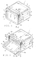
- the electronic appliance 1 shown in Fig. 1 is mounted on the instrument panel of a motor vehicle that is a moving body. As seen from Figs. 1 and 2, the electronic appliance 1 includes an appliance body 2 and an operation display unit 3 that serves as an operation panel.
- the operation display unit 3 is provided with rollers 14 which protrude at upper positions on both sides. The rollers 14 are to be urged by spring pieces 2 fixed to the appliance body 2.
- the appliance body 2 includes a chassis 10 formed like a box, a front face 10a located at the front end of the chassis 10 and on this side in Fig. 3, a reproduction device such as a CD player 6 (not shown) accommodated within the chassis 10 and a driving mechanism 4 (which is partially shown in Fig. 2) which serves to slide the operation display unit 3 for the front face 10a.
- a chassis 10 formed like a box
- a front face 10a located at the front end of the chassis 10 and on this side in Fig. 3
- a reproduction device such as a CD player 6 (not shown) accommodated within the chassis 10
- a driving mechanism 4 which is partially shown in Fig. 2 which serves to slide the operation display unit 3 for the front face 10a.
- upright walls 10c are integrally formed so as to be upright from four sides of the chassis 10.
- the operation display unit 3 is rotatably accommodated in the space formed by the plurality of upright walls 10c.
- Guide grooves (sliding grooves) 16 which extend vertically are formed in the upright walls 10c located on both sides of the operation display unit 3 accommodated in the space.
- the guide grooves 16 are formed in a concave shape from the inner faces of the upright walls 10c.
- the rollers 14 are to be slidably engaged with these guide grooves 16 as described later.
- a through-hole 17 is formed in the vicinity of the upper portion of the guide groove 16 in the upright wall 10c.
- the through-hole 17 penetrates from the above space to the outside of the chassis 10.
- the chassis 10 incorporates a CD player 6 and an MD player 7, which serve as reproducing devices and a CD-ROM player 8 serving as a navigation device.
- the chassis 10 may incorporate an AM/FM tuner for receiving radio broadcasting and a television tuner for receiving a television broadcasting. These reproducing devices and receiving device can operate when a user pushes one of push buttons 18 attached to the operation display unit 3.
- the front face 10a has a slit 12 for inserting an MD into the MD player 7, and slits 13a and 13b for inserting a CD and CD-ROM into the CD player 6 and CD-ROM player 8.
- the driving mechanism 4 includes a pair of arms 19 and a motor (not shown). These arms extend unidirectionally in a belt-shape.
- the arms 19 are slidably supported by the chassis 10 in the longitudinal direction.
- the arms 19 can move along the inner surfaces of both side walls of the chassis 10.
- Each arm 19 has a hole 19a formed at its end (Fig. 4).
- a pair of pins 3b (Fig. 4) which are attached to lower portions on both sides of the operation display unit 3.
- Each pin 3b is rotatably fit in the hole 19a.
- the motor causes each arm to slide relative to the chassis 10. Specifically, owing to the driving force of a motor, each arm 19 is moved from and into the chassis 10 through a through-hole (not shown) formed at the lower end of the front face 10a.
- each arm 19 As each arm 19 is moved from and into the chassis 10, the above roller 14 slides along the guide grooves 16. Specifically, owing to the driving force from the motor, each arm 19 moves outwardly from the chassis 10 so that the operation display unit 3 is brought down with its surface oriented upward. Thus, the operation display unit 3 is shifted to the position where at least a portion of the front face 10a of the chassis is opened (Fig. 2). Further, when each arm 19 is moved into the chassis 10, the operation display unit 3 in the brought state is shifted to the position where it covers the front face 10a of the chassis 10 (Fig. 1). The roller 14 is positioned at the upper end of the guide groove 16.
- the operation display unit 3 is provided with a display panel 5 such as a liquid crystal display (LCD) for displaying image information.
- the operation display unit 3 displays on the display panel the map information reproduced from the CD-ROM player 8 and the image of the television broadcasting received by the television tuner.
- LCD liquid crystal display
- the operation display unit 3 is provided with a plurality of push buttons 18 on the surface. These push buttons 18 are operated in such a manner that they are pushed by the user in the direction of arrow X. When these push buttons are pushed, the various reproducing devices accommodated in the chassis 10 are operated and the operation display unit 3 is slid.
- the select button e.g. button for selecting the CD, MD etc.
- an OPEN button of the push buttons 18 the operation display unit 3 is slide-moved by the driving mechanism 4.
- the MD is selected by the select button, by the driving mechanism, the operation display unit 3 is slid to the position where only the slit 12 formed in the front face 10a of the chassis 10 is opened.
- the operation display unit 3 When the OPEN button is pushed, the operation display unit 3 is slide-moved to the position where all the slots (slit 12 and inserting openings 13a and 13b) are opened.
- the desired disk such as the CD, MD, etc.
- the operation display unit 3 is automatically shifted to the position where it covers the front face 10a of the chassis 10 (it covers all the slots 12, 13a and 13b).
- the operation display unit 3 is shifted to the position where it covers the front face 10a.
- the reproducing button (play) button or search button of the push buttons 18 is pushed by the user, the reproduction or search of the disk is performed.
- the sliding movement is executed in such a manner that the microcomputer (not shown) controls the rotating direction or rotary speed.
- the microcomputer recognizes that the push button 18 has been pushed by the user or the disk has been inserted by the user, and controls the rotary direction and speed of the motor so that the operation display unit 3 is slid to the position corresponding to the operation.
- the rollers 14 are provided so as to be rotatable around shafts at upper ends of both sides of the operation display unit 3.
- the rollers 14 are engaged with the guide grooves 16 to rotate around the shafts so that they can move along the guide grooves 16.
- Each roller 14 is engaged with the guide groove 16 with a slight gap therefrom so that it can smoothly slide along the guide groove.
- the rollers 14 are projected from the sides of the operation display unit 3.
- a spring piece 20 is formed of a metal sheet, and as seen from Figs. 7 and 8, it is integrally composed of an attaching segment 21 and an elastic deforming segment 22.
- the attaching segment 21 is formed of a sheet along the outer face of the upright wall 10c.
- the attaching segment is attached to the appliance body 2 by a screw in such a manner that it is superposed on the outer face of the upright wall 10c.
- the elastic deforming segment 22 is formed in a belt shape.
- the elastic deforming segment 22 is slightly inclined from its one end of the attaching segment 21 upward toward the front face 10a from a bended segment 21a which is bent toward the space formed by the plurality of upright walls 10c.
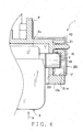
- the attaching segment 21 is attached to the outer face of the upright wall 10c, as seen from Fig. 4, the bent segment 21a and the elastic deforming segment 22 invade the inside of the upright wall 10c through the through-hole 17. Further, the elastic deforming segment 22 is positioned within the guide groove 16.
- the elastic deforming segment 22 When the operation display unit 3 is moved to the position where it covers the front face 10a, the elastic deforming segment 22 is pushed so that it is elastically deformed as shown in Figs. 3 and 5.
- the elastic deforming segment 22 is deformed from the state where it is not pushed by the roller 14 as indicated in solid line in Fig. 8 to the state where it is pushed by roller 14 as indicated in two-dot chain line.
- the elastic deforming segment 22 is located at the upper end of the guide groove 16. Specifically, when the operation display unit 3 is moved to the position where it covers the front face 10a, the roller 14 is located at the upper end of the guide groove 16. Therefore, by locating the elastic deforming segment 22 at the upper end, the elastic deforming segment 22, which is pushed by the roller 14 with its movement is elastically deformed in the state as shown in Fig. 3 or Fig. 4. Further, when the operation display unit 3 is located at the position where it covers the front face 10a, i.e. the roller 14 is brought into contact with the elastic deforming segment 22, the elastic deforming segment 22 is located within the guide groove 16 so that it is opposite to the front face 10a with respect to the roller 14.
- the roller 14 pushes the elastic deforming segment 22 so as to be elastically deformed, and the elastic deforming segment 22 urges the operation display unit 3 in the direction of arrow Y in Fig. 5 by its restoring force.
- the roller 14 is pushed on the side wall near to the front face 10a of the guide groove 16 so that the operation display unit 3 itself is secured to the appliance body 2.
- the urging direction of the elastic deforming segment 22 is substantially the same as the direction (the direction indicated by arrow X in Figs. 1 and 5) of the pushing force applied when the push button 18 is operated. Therefore, when the user pushes the bushing button 18, the operation display unit 3 is not moved. For this reason, the user is given good tactile feel.
- the operation display unit 3 when the MD, CD, or CD-ROM is inserted into the appliance body 2, the operation display unit 3 is located at the position as shown in Figs. 2 and 4. In this case, the elastic deforming portion 22 of the spring 20 is held in the state where it is not in contact with the roller 14 and not elastically deformed.
- the operation display unit 3 is moved to the position shown in Figs. 1 and 3.
- the elastic deforming portion 22 is elastically deformed in contact with the roller 14 and urges the roller 14 toward the front face 10a in the direction of arrow Y.
- the elastic deforming segment 22 urges the roller 14 in the direction of the rear face 3c of the operation display unit 3 being oriented to the inner side of the appliance body 2.
- the elastic deforming segment 22 when the operation display unit 3 covers the front face 10a, the elastic deforming segment 22 is located on the opposite side to the front face 10a with respect to the roller 14. Namely, the elastic deforming segment 22 is located on the side of the roller 14 far from the appliance body 2. Therefore, the elastic deforming segment 22 is located on the side of the roller 14 near to the user.
- the elastic deforming segment 22 is elastically deformed in contact with the roller 14 which is rotatably provided at the upper end on each of both sides of the operation display unit 3. Therefore, the elastic deforming segment 22 urges the roller 14 and hence the operation display unit 3 toward the front face 10a in the direction of arrow Y. Namely, the elastic deforming segment 22 surely urges the roller 14 in the direction of the rear face 3c of the operation display unit 3 being oriented to the inner side of the appliance body 2.
- the elastic deforming segment 22 urges the operation display unit 3 in the same direction as that of operating the push button 18 indicated by arrow X.
- the push button 18 is pushed toward the inner side of the appliance body 2, the operation display unit 3 will not be moved. For this reason, the push button 18 can be operated satisfactorily with no sense of incongruity and with good tactile feel.
- the attaching segment 21 of the spring piece 20 is secured to the appliance body 2, and the elastic deforming segment 2 is located within the guide groove 16 which is a sliding path of the roller 14. Therefore, when the operation display unit 3 is only situated at the position where it covers the front face 10a, the elastic deforming segment 22 can urge the roller 14 and hence the operation display unit 3. For this reason, any specific mechanism for causing the spring piece 20 to urge the operation display unit 3 is not required, but the operation display unit 3 can be urged by a simple configuration. When the roller 14 is brought into contact the elastic deforming segment 22 so that the former pushes and elastically deforms the latter, the restoring force against the pushing force by the roller 14 can be surely applied to the roller 14. Thus, the operation display unit 3 can be surely urged.
- a plurality of push buttons 18 are provided on the display panel 5 of the operation display unit 3.
- a touch switch or touch panel may be provided on the display panel.
Landscapes
- Engineering & Computer Science (AREA)
- Multimedia (AREA)
- Casings For Electric Apparatus (AREA)
Abstract
Description
the operation panel is provided with a rotatable roller,
the appliance body has a sliding groove with which the roller is slidably engaged,
the operation panel slides relatively to the face while the roller rolls along the sliding groove, and
when the operation panel is situated at the position where it covers the face, the roller is urged by the urging unit.
Claims (4)
- An electric appliance comprising:an appliance body;an operation panel which is slidably attached to a face of said appliance body and can slide-move between a position where it covers the face and another position where it opens at least a portion of-the face; andan urging unit attached to the appliance body for urging said operation panel, whereinwhen said operation panel is situated at the position where it covers said face, said urging unit urges said operation panel toward the face of said appliance body.
- An electric appliance according to claim 1, wherein
said operation panel is provided with a rotatable roller,
said appliance body has a sliding groove with which said roller is slidably engaged,
said operation panel slide-moves relatively to said face while the roller rolls along the sliding groove, and
when said operation panel is situated at the position where it covers the face, said roller is urged by said urging unit. - An electric appliance according to Claim 2, wherein said urging unit is a spring piece composed of an attaching segment attached to said appliance body and an elastic deforming segment which is located within said sliding groove and elastically deformed in contact with said roller.
- An electric appliance according to claim 3, wherein when said operation panel is at the position where it covers said face, said elastic deforming segment is situated within said groove at a position opposite to said face with respect to said roller.
Applications Claiming Priority (2)
| Application Number | Priority Date | Filing Date | Title |
|---|---|---|---|
| JP2001342931 | 2001-11-08 | ||
| JP2001342931A JP3730564B2 (en) | 2001-11-08 | 2001-11-08 | Electronics |
Publications (2)
| Publication Number | Publication Date |
|---|---|
| EP1310958A2 true EP1310958A2 (en) | 2003-05-14 |
| EP1310958A3 EP1310958A3 (en) | 2004-07-07 |
Family
ID=19156706
Family Applications (1)
| Application Number | Title | Priority Date | Filing Date |
|---|---|---|---|
| EP02024952A Withdrawn EP1310958A3 (en) | 2001-11-08 | 2002-11-06 | Electronic appliance |
Country Status (3)
| Country | Link |
|---|---|
| US (1) | US7137676B2 (en) |
| EP (1) | EP1310958A3 (en) |
| JP (1) | JP3730564B2 (en) |
Families Citing this family (19)
| Publication number | Priority date | Publication date | Assignee | Title |
|---|---|---|---|---|
| JP4251765B2 (en) * | 2000-10-03 | 2009-04-08 | アルパイン株式会社 | Automotive electronics |
| KR100503309B1 (en) * | 2003-06-16 | 2005-07-25 | 현대모비스 주식회사 | monitor structure to prevent from moving freely for audio/video system having monitor tilting apparatus |
| KR100520991B1 (en) * | 2003-09-15 | 2005-10-11 | 현대모비스 주식회사 | driving assembly of audio/video system for a vehicle |
| US7356954B2 (en) * | 2003-12-01 | 2008-04-15 | Fujitsu Ten Limited | In-vehicle display apparatus |
| JP2006012262A (en) * | 2004-06-24 | 2006-01-12 | Alpine Electronics Inc | Electronic apparatus and its medium ejection method |
| US20070063826A1 (en) * | 2005-09-16 | 2007-03-22 | Kwang Baig | In-vehicle multifunctional information device |
| JP4984468B2 (en) * | 2005-09-26 | 2012-07-25 | ブラザー工業株式会社 | Electronics |
| JP2007265461A (en) * | 2006-03-27 | 2007-10-11 | Denso Corp | In-vehicle device |
| KR100911085B1 (en) * | 2007-06-26 | 2009-08-06 | 현대자동차주식회사 | Car folding monitor |
| USD582807S1 (en) * | 2007-11-20 | 2008-12-16 | Alpine Electronics, Inc. | Vehicle navigation unit with digital video player |
| JP4683062B2 (en) * | 2008-03-25 | 2011-05-11 | 株式会社デンソー | In-vehicle device |
| JP2010083464A (en) * | 2008-10-03 | 2010-04-15 | Fujitsu Ten Ltd | In-vehicle device and holding member |
| USD597424S1 (en) * | 2008-12-01 | 2009-08-04 | Clarion Co., Ltd. | Navigation system with digital audio player |
| USD613733S1 (en) * | 2008-12-17 | 2010-04-13 | Alpine Electronics, Inc. | Digital audio player with tuner for vehicle |
| USD608774S1 (en) * | 2008-12-17 | 2010-01-26 | Alpine Electronics, Inc. | Digital audio player with tuner for vehicle |
| USD622734S1 (en) * | 2009-12-23 | 2010-08-31 | Clarion Co., Ltd. | Digital disc player |
| AU2012382071B2 (en) | 2012-06-06 | 2017-04-06 | Schneider Electric It Corporation | Uninterruptible power supply having adjustable interface |
| JP6794210B2 (en) * | 2016-10-11 | 2020-12-02 | キヤノン株式会社 | Image forming device |
| JP7221081B2 (en) * | 2019-02-28 | 2023-02-13 | 株式会社Jvcケンウッド | Detection device, cam mechanism, and sealing body opening method |
Family Cites Families (15)
| Publication number | Priority date | Publication date | Assignee | Title |
|---|---|---|---|---|
| DE3544054A1 (en) * | 1985-12-13 | 1987-06-19 | Idn Invention Dev Novelties | STORAGE CONTAINER FOR RECORDS |
| US4718740A (en) * | 1986-10-28 | 1988-01-12 | Allied Corporation | Housing and stowage mechanism for terminal keyboard and display panel |
| US5276589A (en) * | 1992-11-09 | 1994-01-04 | Ncr Corporation | Notebook computer having flip screen which pivots and slides within a frame |
| AU6496594A (en) * | 1993-03-26 | 1994-10-24 | Khalil S. Zaidan | Hinge assembly for electronic devices |
| KR100261754B1 (en) * | 1996-04-03 | 2000-07-15 | 윤종용 | Computers with Peripheral Protection |
| JP3100344B2 (en) | 1996-10-23 | 2000-10-16 | 株式会社ハーネス総合技術研究所 | Display opening / closing structure |
| US5941615A (en) * | 1996-10-23 | 1999-08-24 | Harness System Technologies Research, Ltd. | Movable structure for a display |
| JP3850529B2 (en) | 1997-10-01 | 2006-11-29 | 小島プレス工業株式会社 | Pop-up display |
| JPH11227538A (en) | 1998-02-19 | 1999-08-24 | Clarion Co Ltd | Electronic device with panel opening device |
| JP3561425B2 (en) | 1998-10-09 | 2004-09-02 | 株式会社オートネットワーク技術研究所 | Display device opening / closing mechanism |
| JP2000194448A (en) * | 1998-12-25 | 2000-07-14 | Nec Corp | Electronic computer having file bay cover with electronic lock and its control method |
| US6633347B2 (en) * | 2001-01-02 | 2003-10-14 | Alpine Electronics, Inc. | Display assembly having display supported on casing to be controllable in attitude |
| US6603655B2 (en) * | 2001-08-03 | 2003-08-05 | Dell Products L.P. | Rotating and translating four bar media door for a computer chassis |
| US6557385B1 (en) * | 2001-12-14 | 2003-05-06 | Shoei-Yuan Shih | Safety and anti-theft door guard for a server |
| US6578935B1 (en) * | 2002-03-22 | 2003-06-17 | Scosche Industries, Inc. | Slider tray storage apparatus |
-
2001
- 2001-11-08 JP JP2001342931A patent/JP3730564B2/en not_active Expired - Fee Related
-
2002
- 2002-10-17 US US10/272,006 patent/US7137676B2/en not_active Expired - Fee Related
- 2002-11-06 EP EP02024952A patent/EP1310958A3/en not_active Withdrawn
Also Published As
| Publication number | Publication date |
|---|---|
| US20030085325A1 (en) | 2003-05-08 |
| JP3730564B2 (en) | 2006-01-05 |
| JP2003151253A (en) | 2003-05-23 |
| EP1310958A3 (en) | 2004-07-07 |
| US7137676B2 (en) | 2006-11-21 |
Similar Documents
| Publication | Publication Date | Title |
|---|---|---|
| EP1310958A2 (en) | Electronic appliance | |
| JP4401552B2 (en) | Electronic device and button device transmission device used therefor | |
| EP1195284B1 (en) | Vehicle-mounted electronic apparatus | |
| KR100944759B1 (en) | Electronics | |
| US7304836B2 (en) | Electronic apparatus | |
| US7884297B2 (en) | Electronic apparatus | |
| JP3787891B2 (en) | In-vehicle audiovisual equipment | |
| WO2000034079A1 (en) | Dual mode car stereo system capable of playing two different types of recording mediums | |
| JPH07160203A (en) | Display device | |
| US6986672B2 (en) | Electric contact structure, process for producing the same and electronic instrument having the same | |
| JP3353271B2 (en) | Automotive electronics | |
| JP2008226350A (en) | Electronic apparatus | |
| JP3186966B2 (en) | In-vehicle audio-visual equipment | |
| JP3824448B2 (en) | Electronic device moving unit guide device | |
| JPH1051154A (en) | Push button mechanism and unlock push button mechanism | |
| JP4252857B2 (en) | Electronic equipment | |
| EP1536430B1 (en) | Reproducing apparatus | |
| JP2002087174A (en) | On-vehicle electronic equipment | |
| KR20000033789A (en) | Car audio with front panel tilting structure | |
| KR100246042B1 (en) | Car Audio System | |
| JP2009120075A (en) | Slope mechanism and on-vehicle acoustic device equipped with the same | |
| JP3647297B2 (en) | Automotive electronics | |
| JP2513200Y2 (en) | Recording medium playing device | |
| JP3365906B2 (en) | Dustproof door opening and closing mechanism | |
| JP2004017674A (en) | Housing with panel |
Legal Events
| Date | Code | Title | Description |
|---|---|---|---|
| PUAI | Public reference made under article 153(3) epc to a published international application that has entered the european phase |
Free format text: ORIGINAL CODE: 0009012 |
|
| AK | Designated contracting states |
Designated state(s): AT BE BG CH CY CZ DE DK EE ES FI FR GB GR IE IT LI LU MC NL PT SE SK TR |
|
| AX | Request for extension of the european patent |
Extension state: AL LT LV MK RO SI |
|
| PUAL | Search report despatched |
Free format text: ORIGINAL CODE: 0009013 |
|
| AK | Designated contracting states |
Kind code of ref document: A3 Designated state(s): AT BE BG CH CY CZ DE DK EE ES FI FR GB GR IE IT LI LU MC NL PT SE SK TR |
|
| AX | Request for extension of the european patent |
Extension state: AL LT LV MK RO SI |
|
| RIC1 | Information provided on ipc code assigned before grant |
Ipc: 7B 60R 7/08 B Ipc: 7B 60R 11/02 B Ipc: 7G 11B 33/12 A |
|
| 17P | Request for examination filed |
Effective date: 20040629 |
|
| 17Q | First examination report despatched |
Effective date: 20040805 |
|
| AKX | Designation fees paid |
Designated state(s): DE FR GB |
|
| GRAP | Despatch of communication of intention to grant a patent |
Free format text: ORIGINAL CODE: EPIDOSNIGR1 |
|
| GRAS | Grant fee paid |
Free format text: ORIGINAL CODE: EPIDOSNIGR3 |
|
| 17Q | First examination report despatched |
Effective date: 20040805 |
|
| GRAJ | Information related to disapproval of communication of intention to grant by the applicant or resumption of examination proceedings by the epo deleted |
Free format text: ORIGINAL CODE: EPIDOSDIGR1 |
|
| GRAS | Grant fee paid |
Free format text: ORIGINAL CODE: EPIDOSNIGR3 |
|
| GRAP | Despatch of communication of intention to grant a patent |
Free format text: ORIGINAL CODE: EPIDOSNIGR1 |
|
| GRAS | Grant fee paid |
Free format text: ORIGINAL CODE: EPIDOSNIGR3 |
|
| STAA | Information on the status of an ep patent application or granted ep patent |
Free format text: STATUS: THE APPLICATION IS DEEMED TO BE WITHDRAWN |
|
| 18D | Application deemed to be withdrawn |
Effective date: 20080601 |