EP1310903B1 - Kompakter Strichcodeabtaster mit Stossschutz - Google Patents
Kompakter Strichcodeabtaster mit Stossschutz Download PDFInfo
- Publication number
- EP1310903B1 EP1310903B1 EP03003186A EP03003186A EP1310903B1 EP 1310903 B1 EP1310903 B1 EP 1310903B1 EP 03003186 A EP03003186 A EP 03003186A EP 03003186 A EP03003186 A EP 03003186A EP 1310903 B1 EP1310903 B1 EP 1310903B1
- Authority
- EP
- European Patent Office
- Prior art keywords
- pattern
- barcode
- scan
- scanning
- indicia
- Prior art date
- Legal status (The legal status is an assumption and is not a legal conclusion. Google has not performed a legal analysis and makes no representation as to the accuracy of the status listed.)
- Expired - Lifetime
Links
Images


Classifications
-
- G—PHYSICS
- G06—COMPUTING; CALCULATING OR COUNTING
- G06K—GRAPHICAL DATA READING; PRESENTATION OF DATA; RECORD CARRIERS; HANDLING RECORD CARRIERS
- G06K7/00—Methods or arrangements for sensing record carriers, e.g. for reading patterns
- G06K7/10—Methods or arrangements for sensing record carriers, e.g. for reading patterns by electromagnetic radiation, e.g. optical sensing; by corpuscular radiation
- G06K7/10544—Methods or arrangements for sensing record carriers, e.g. for reading patterns by electromagnetic radiation, e.g. optical sensing; by corpuscular radiation by scanning of the records by radiation in the optical part of the electromagnetic spectrum
- G06K7/10821—Methods or arrangements for sensing record carriers, e.g. for reading patterns by electromagnetic radiation, e.g. optical sensing; by corpuscular radiation by scanning of the records by radiation in the optical part of the electromagnetic spectrum further details of bar or optical code scanning devices
- G06K7/10861—Methods or arrangements for sensing record carriers, e.g. for reading patterns by electromagnetic radiation, e.g. optical sensing; by corpuscular radiation by scanning of the records by radiation in the optical part of the electromagnetic spectrum further details of bar or optical code scanning devices sensing of data fields affixed to objects or articles, e.g. coded labels
- G06K7/10871—Methods or arrangements for sensing record carriers, e.g. for reading patterns by electromagnetic radiation, e.g. optical sensing; by corpuscular radiation by scanning of the records by radiation in the optical part of the electromagnetic spectrum further details of bar or optical code scanning devices sensing of data fields affixed to objects or articles, e.g. coded labels randomly oriented data-fields, code-marks therefore, e.g. concentric circles-code
-
- G—PHYSICS
- G06—COMPUTING; CALCULATING OR COUNTING
- G06K—GRAPHICAL DATA READING; PRESENTATION OF DATA; RECORD CARRIERS; HANDLING RECORD CARRIERS
- G06K7/00—Methods or arrangements for sensing record carriers, e.g. for reading patterns
- G06K7/10—Methods or arrangements for sensing record carriers, e.g. for reading patterns by electromagnetic radiation, e.g. optical sensing; by corpuscular radiation
- G06K7/10544—Methods or arrangements for sensing record carriers, e.g. for reading patterns by electromagnetic radiation, e.g. optical sensing; by corpuscular radiation by scanning of the records by radiation in the optical part of the electromagnetic spectrum
- G06K7/10554—Moving beam scanning
- G06K7/10564—Light sources
- G06K7/10584—Source control
-
- G—PHYSICS
- G06—COMPUTING; CALCULATING OR COUNTING
- G06K—GRAPHICAL DATA READING; PRESENTATION OF DATA; RECORD CARRIERS; HANDLING RECORD CARRIERS
- G06K7/00—Methods or arrangements for sensing record carriers, e.g. for reading patterns
- G06K7/10—Methods or arrangements for sensing record carriers, e.g. for reading patterns by electromagnetic radiation, e.g. optical sensing; by corpuscular radiation
- G06K7/10544—Methods or arrangements for sensing record carriers, e.g. for reading patterns by electromagnetic radiation, e.g. optical sensing; by corpuscular radiation by scanning of the records by radiation in the optical part of the electromagnetic spectrum
- G06K7/10554—Moving beam scanning
- G06K7/10594—Beam path
- G06K7/10603—Basic scanning using moving elements
- G06K7/10633—Basic scanning using moving elements by oscillation
- G06K7/10643—Activating means
- G06K7/10653—Activating means using flexible or piezoelectric means
-
- G—PHYSICS
- G06—COMPUTING; CALCULATING OR COUNTING
- G06K—GRAPHICAL DATA READING; PRESENTATION OF DATA; RECORD CARRIERS; HANDLING RECORD CARRIERS
- G06K7/00—Methods or arrangements for sensing record carriers, e.g. for reading patterns
- G06K7/10—Methods or arrangements for sensing record carriers, e.g. for reading patterns by electromagnetic radiation, e.g. optical sensing; by corpuscular radiation
- G06K7/10544—Methods or arrangements for sensing record carriers, e.g. for reading patterns by electromagnetic radiation, e.g. optical sensing; by corpuscular radiation by scanning of the records by radiation in the optical part of the electromagnetic spectrum
- G06K7/10554—Moving beam scanning
- G06K7/10594—Beam path
- G06K7/10603—Basic scanning using moving elements
- G06K7/10673—Parallel lines
-
- G—PHYSICS
- G06—COMPUTING; CALCULATING OR COUNTING
- G06K—GRAPHICAL DATA READING; PRESENTATION OF DATA; RECORD CARRIERS; HANDLING RECORD CARRIERS
- G06K7/00—Methods or arrangements for sensing record carriers, e.g. for reading patterns
- G06K7/10—Methods or arrangements for sensing record carriers, e.g. for reading patterns by electromagnetic radiation, e.g. optical sensing; by corpuscular radiation
- G06K7/10544—Methods or arrangements for sensing record carriers, e.g. for reading patterns by electromagnetic radiation, e.g. optical sensing; by corpuscular radiation by scanning of the records by radiation in the optical part of the electromagnetic spectrum
- G06K7/10554—Moving beam scanning
- G06K7/10594—Beam path
- G06K7/10683—Arrangement of fixed elements
- G06K7/10693—Arrangement of fixed elements for omnidirectional scanning
-
- G—PHYSICS
- G06—COMPUTING; CALCULATING OR COUNTING
- G06K—GRAPHICAL DATA READING; PRESENTATION OF DATA; RECORD CARRIERS; HANDLING RECORD CARRIERS
- G06K7/00—Methods or arrangements for sensing record carriers, e.g. for reading patterns
- G06K7/10—Methods or arrangements for sensing record carriers, e.g. for reading patterns by electromagnetic radiation, e.g. optical sensing; by corpuscular radiation
- G06K7/10544—Methods or arrangements for sensing record carriers, e.g. for reading patterns by electromagnetic radiation, e.g. optical sensing; by corpuscular radiation by scanning of the records by radiation in the optical part of the electromagnetic spectrum
- G06K7/10792—Special measures in relation to the object to be scanned
- G06K7/10801—Multidistance reading
- G06K7/10811—Focalisation
-
- G—PHYSICS
- G06—COMPUTING; CALCULATING OR COUNTING
- G06K—GRAPHICAL DATA READING; PRESENTATION OF DATA; RECORD CARRIERS; HANDLING RECORD CARRIERS
- G06K7/00—Methods or arrangements for sensing record carriers, e.g. for reading patterns
- G06K7/10—Methods or arrangements for sensing record carriers, e.g. for reading patterns by electromagnetic radiation, e.g. optical sensing; by corpuscular radiation
- G06K7/10544—Methods or arrangements for sensing record carriers, e.g. for reading patterns by electromagnetic radiation, e.g. optical sensing; by corpuscular radiation by scanning of the records by radiation in the optical part of the electromagnetic spectrum
- G06K7/10821—Methods or arrangements for sensing record carriers, e.g. for reading patterns by electromagnetic radiation, e.g. optical sensing; by corpuscular radiation by scanning of the records by radiation in the optical part of the electromagnetic spectrum further details of bar or optical code scanning devices
- G06K7/10851—Circuits for pulse shaping, amplifying, eliminating noise signals, checking the function of the sensing device
-
- G—PHYSICS
- G06—COMPUTING; CALCULATING OR COUNTING
- G06K—GRAPHICAL DATA READING; PRESENTATION OF DATA; RECORD CARRIERS; HANDLING RECORD CARRIERS
- G06K7/00—Methods or arrangements for sensing record carriers, e.g. for reading patterns
- G06K7/10—Methods or arrangements for sensing record carriers, e.g. for reading patterns by electromagnetic radiation, e.g. optical sensing; by corpuscular radiation
- G06K7/10544—Methods or arrangements for sensing record carriers, e.g. for reading patterns by electromagnetic radiation, e.g. optical sensing; by corpuscular radiation by scanning of the records by radiation in the optical part of the electromagnetic spectrum
- G06K7/10821—Methods or arrangements for sensing record carriers, e.g. for reading patterns by electromagnetic radiation, e.g. optical sensing; by corpuscular radiation by scanning of the records by radiation in the optical part of the electromagnetic spectrum further details of bar or optical code scanning devices
- G06K7/10881—Methods or arrangements for sensing record carriers, e.g. for reading patterns by electromagnetic radiation, e.g. optical sensing; by corpuscular radiation by scanning of the records by radiation in the optical part of the electromagnetic spectrum further details of bar or optical code scanning devices constructional details of hand-held scanners
- G06K7/10891—Methods or arrangements for sensing record carriers, e.g. for reading patterns by electromagnetic radiation, e.g. optical sensing; by corpuscular radiation by scanning of the records by radiation in the optical part of the electromagnetic spectrum further details of bar or optical code scanning devices constructional details of hand-held scanners the scanner to be worn on a finger or on a wrist
-
- G—PHYSICS
- G06—COMPUTING; CALCULATING OR COUNTING
- G06K—GRAPHICAL DATA READING; PRESENTATION OF DATA; RECORD CARRIERS; HANDLING RECORD CARRIERS
- G06K7/00—Methods or arrangements for sensing record carriers, e.g. for reading patterns
- G06K7/10—Methods or arrangements for sensing record carriers, e.g. for reading patterns by electromagnetic radiation, e.g. optical sensing; by corpuscular radiation
- G06K7/10544—Methods or arrangements for sensing record carriers, e.g. for reading patterns by electromagnetic radiation, e.g. optical sensing; by corpuscular radiation by scanning of the records by radiation in the optical part of the electromagnetic spectrum
- G06K7/10821—Methods or arrangements for sensing record carriers, e.g. for reading patterns by electromagnetic radiation, e.g. optical sensing; by corpuscular radiation by scanning of the records by radiation in the optical part of the electromagnetic spectrum further details of bar or optical code scanning devices
- G06K7/10881—Methods or arrangements for sensing record carriers, e.g. for reading patterns by electromagnetic radiation, e.g. optical sensing; by corpuscular radiation by scanning of the records by radiation in the optical part of the electromagnetic spectrum further details of bar or optical code scanning devices constructional details of hand-held scanners
- G06K7/109—Methods or arrangements for sensing record carriers, e.g. for reading patterns by electromagnetic radiation, e.g. optical sensing; by corpuscular radiation by scanning of the records by radiation in the optical part of the electromagnetic spectrum further details of bar or optical code scanning devices constructional details of hand-held scanners adaptations to make the hand-held scanner useable as a fixed scanner
-
- G—PHYSICS
- G06—COMPUTING; CALCULATING OR COUNTING
- G06K—GRAPHICAL DATA READING; PRESENTATION OF DATA; RECORD CARRIERS; HANDLING RECORD CARRIERS
- G06K7/00—Methods or arrangements for sensing record carriers, e.g. for reading patterns
- G06K7/10—Methods or arrangements for sensing record carriers, e.g. for reading patterns by electromagnetic radiation, e.g. optical sensing; by corpuscular radiation
- G06K7/10544—Methods or arrangements for sensing record carriers, e.g. for reading patterns by electromagnetic radiation, e.g. optical sensing; by corpuscular radiation by scanning of the records by radiation in the optical part of the electromagnetic spectrum
- G06K7/10821—Methods or arrangements for sensing record carriers, e.g. for reading patterns by electromagnetic radiation, e.g. optical sensing; by corpuscular radiation by scanning of the records by radiation in the optical part of the electromagnetic spectrum further details of bar or optical code scanning devices
- G06K7/1098—Methods or arrangements for sensing record carriers, e.g. for reading patterns by electromagnetic radiation, e.g. optical sensing; by corpuscular radiation by scanning of the records by radiation in the optical part of the electromagnetic spectrum further details of bar or optical code scanning devices the scanning arrangement having a modular construction
-
- G—PHYSICS
- G06—COMPUTING; CALCULATING OR COUNTING
- G06K—GRAPHICAL DATA READING; PRESENTATION OF DATA; RECORD CARRIERS; HANDLING RECORD CARRIERS
- G06K2207/00—Other aspects
- G06K2207/1011—Aiming
-
- G—PHYSICS
- G06—COMPUTING; CALCULATING OR COUNTING
- G06K—GRAPHICAL DATA READING; PRESENTATION OF DATA; RECORD CARRIERS; HANDLING RECORD CARRIERS
- G06K2207/00—Other aspects
- G06K2207/1016—Motor control or optical moving unit control
-
- G—PHYSICS
- G06—COMPUTING; CALCULATING OR COUNTING
- G06K—GRAPHICAL DATA READING; PRESENTATION OF DATA; RECORD CARRIERS; HANDLING RECORD CARRIERS
- G06K2207/00—Other aspects
- G06K2207/1018—Source control
Definitions
- This invention relates generally to hand-held scanning systems which "read" indicia, such as barcode symbols, and in particular to systems and methods for scanning one-dimensional (1-D) and two-dimensional (2-D) barcode symbols with a first scan pattern that is relatively small and dense so as to be visible to the user, and thereafter a second, larger and more robust scan pattern for decoding.
- the invention also relates to scanners operable in both portable (hand-held) and surface mounted (hands-free) modes for reading various types of indicia.
- the invention further relates to novel miniature assemblies capable of 1-D and 2-D scanning. It further relates to a scanner module for use in an optical scanner, for example, a bar code scanner.
- the barcode symbol itself is a coded pattern of indicia comprised of a series of bars of various widths spaced apart from one another to bound spaces of various widths, the bars and spaces having different light-reflecting characteristics.
- the readers and scanning systems electro-optically transform the graphic indicia into electrical signals, which are decoded into alpha-numerical characters intended to be descriptive of the article or some characteristic of it. Such characters typically are represented in digital form, and utilized as an input to a data processing system for applications in point-of-sale processing, inventory control and the like. Scanning systems of this general type have been disclosed, for example, in U.S. Patent Nos. 4,251,798 ; 4,360,798 ; 4,369,361 ; 4,387,297 ; 4,409,470 and 4,460,120 .
- a scanning system resides in, inter alia, a hand-held, portable laser scanning head supported by a user.
- the scanning head is configured to enable the user to aim the head at a target to emit a light beam toward a symbol to be read.
- the light source is a laser scanner typically in the form of a gas or semiconductor laser element.
- Use of semiconductor devices as the light source in scanning systems is particularly desirable because of the small size, low cost and low power requirements of semiconductor lasers.
- the laser beam is optically modified, typically by a lens, to form a beam spot of a certain size at the target distance.
- the beam spot size at the target distance is approximately the same as the minimum width between regions of different light reflectivity, i.e., the bars and spaces of the symbol.
- the barcode symbols are formed from bars or elements typically rectangular in shape with a variety of possible widths.
- the specific arrangement of elements defines the character represented according to a set of rules and definitions specified by the code or "symbology" used.
- the relative size of the bars and spaces is determined by the type of coding used, as is the actual size of the bars and spaces.
- the number of characters per inch represented by the barcode symbol is referred to as the density of the symbol.
- To encode a desired sequence of characters a collection of element arrangements are concatenated together to form the complete barcode symbol, with each character of the message being represented by its own corresponding group of elements. In some symbologies a unique "start” and "stop” character is used to indicate where the barcode begins and ends.
- a number of different barcode symbologies exist. These symbologies include UPC/EAN, Code 39, Code 128, Codabar, and Interleaved 2 or 5.
- Code 49 introduces a "two-dimensional" concept by stacking rows of characters vertically instead of extending the bars horizontally. That is, there are several rows of bar and space pattern, instead of only one row.
- the structure of Code 49 is described in U.S. Patent 4,794,239 .
- a one-dimensional single-line scan functions by repetitively scanning the light beam in a line or series of lines across the symbol using a scanning component such as a, mirror disposed in the light path.
- the scanning component may either sweep the beam spot across the symbol and trace a scan line across and past the symbol, or scan the field in view of the scanner, or do both.
- Scanning systems also include a sensor or photodetector, usually of semiconductor type, which functions to detect light reflected from the symbol.
- the photo-detector is therefore positioned in the scanner or in an optical path in which it has a field of view which extends across and slightly past the symbol.
- a portion of the reflected light which is reflected off the symbol is detected and converted into an electrical signal, and electronic circuitry or software decodes the electrical signal into a digital representation of the data represented by the symbol that has been scanned.
- the analog electrical signal from the photodetector may typically be converted into a pulse width modulated digital signal, with the widths corresponding to the physical widths of the bars and spaces. Such a signal is then decoded according to the specific symbology into a binary representation of the data encoded in the symbol, and to the alphanumeric characters so represented.
- the decoding process in known scanning systems usually works in the following waxy.
- the decoder receives the pulse width modulated digital signal from the scanner, and an algorithm implemented in software attempts to decode the scan. If the start and stop characters and the characters between them in the scan were decoded successfully and completely, the decoding process terminates and an indicator of a successful read (such as a green light and/or an audible beep) is provided to the user. Otherwise, the decoder receives the next scan, performs another decode attempt on that scan, and so on, until a completely decoded scan is achieved or no more scans are available.
- a successful read such as a green light and/or an audible beep
- More sophisticated scanning carries out selective scanning of 1-D and 2-D barcodes.
- Preliminary information such as the barcode type and size, is preliminarily decoded during an aiming mode of operation when a relatively narrow and visible raster pattern is impinged on the target.
- Scanning 2-D, or PDF, barcodes with a raster pattern also presents a similar problem.
- the visibility of a 2-D raster pattern is poorer than that of a single line, and orienting the barcode with the scan lines is not effortless.
- the user may tend to position the 2-D barcode horizontally under a scan lamp.
- a 2-D barcode may have been a photocopy vertically aligned onto a page. Upon scanning, the user may first subconsciously attempt to present the page horizontally, and thus present the barcode vertically. Without ability by the scanner to instantaneously sense barcode orientation, and then position a raster pattern to scan it, the user will be forced to realign the page vertically.
- the pattern is then increased in width so as to fully span the length of the barcode, and if the pattern is determined to be a 2-D barcode, the height of the scan pattern is also increased so as to decode all of the barcode rows.
- the rate at which the raster pattern is increased in size is fixed and independent of the size of the barcode or the distance between the hand-held scanner and target.
- Pattern size is incremented until the entire pattern is decoded. The size of each increment of increase is determined in part by the working range of the scanner.
- Very long range scanners usable up to sixty feet, for example, may require smaller increments so that the patterns do not grow too fast at the end of a working range where much of the information, including start and stop codes, concerning attributes of the barcode resides.
- the scanner unit must be compact, energy efficient, and capable of scanning both 1-D and 2-D barcodes.
- the unit preferably will also be convertible between hand and surface support applications.
- the scan pattern will preferably be optimized in accordance with whether the unit is in hand held or surface supported modes of operation, whether it is in a presentation type of operation (wherein the indicia are passed under a scan lamp) or a pass through type of operation (supermarket type) and on the type of barcode or other indicia to be read.
- EP-A-0 574 024 discloses an adaptive bar code scanner and forms part of the prior art pursuant to Art. 54(3) EPC. Reference will now be made to further aspects of known scanners.
- a typical optical scanner for example a bar code scanner
- has a light source preferably a laser light source, and means for directing the laser beam onto a symbol (for example a bar code) to be read.
- the laser beam is generally directed onto, and reflected off, a light reflecting mirror of a scanning component.
- the scanning component causes oscillation of the mirror, so causing the laser beam repetitively to scan the symbol.
- Light reflected from the symbol is collected by the scanner and detected by a detector such as a photodiode.
- Decode circuitry and/or a microprocessor algorithm is provided to enable the reflected light to be decode, thereby recovering the data which is recorded by the bar code symbol.
- Scanners of this general type have been disclosed, for example, in US Patents 4 251 798 ; 4 360 798 ; 4 369 361 ; 4 387 297 ; 4 593 186 ; 4 496 831 ; 4 409 470 ; 4 808 804 ; 4 816 661 ; 4 816 660 ; and 4 871 904 .
- a general object of this invention is to improve aim and shoot capabilities of hand-held barcode scanners. Another object of the invention is to implement robust scan patterns during decoding, and another is to enable the scanner to automatically orient the scan pattern to the rotational orientation of the symbol. A further object is to transition between aiming and decoding automatically while reading 1-D or 2-D barcodes. Other objects of this invention include providing convertibility between hand-held and surface mount applications while automatically generating scan patterns optimized for the particular application and type of indicia being read.
- a light beam scanner generates a light beam directed toward a symbol to be read and moves the beam along the symbol in an omnidirectional scanning pattern, that is, one wherein the pattern trajectory is not limited to one or a limited number of directions while a symbol is traversed.
- a light detector receives reflected light from the symbol and generates electrical signals responsive to the reflected light, and the scanning pattern is controlled in response to the electric signals.
- the scanning pattern may be radially symmetric, a rotating line pattern, or a spiral pattern.
- the pattern control may vary the diameter or trajectory of the light beam, and more particularly may move the light beam selectively along a first scan path or a second scan path depending on the electrical signals.
- the first and second scan paths differ from each other by rotation about an axis of rotation, by an increase in scan path envelope diameter, by rotation of the first scan path about an axis of rotation and increase of scan path envelope diameter, or by displacement of the center of rotation of the first scan pattern.
- the scan pattern is such that the bar code is traversed by at least two scan lines per row of bar patterns during reading.
- a particular arrangement of the foregoing includes providing a relatively bright, rosette scanning pattern for enabling a user to aim and direct the beam toward a bar code symbol to be read, scanning the symbol detecting light reflected from the symbol and generating an electrical signal in response to the reflected light, and modifying the radial diameter of the scan pattern in response to the electrical signal.
- a light source for generating a light beam directed toward a symbol to be read, and a light detector for receiving light reflected from the symbol and, in response, generating an electrical signal. This signal is converted to data corresponding to a content of the symbol.
- the light beam is controlled to scan the symbol with a prescribed scan pattern to develop first data, and thereafter increase a dimension of the scan pattern at a rate dependent upon that first data.
- the scan pattern is increased in dimension at a rate, and to a magnitude, that are determined by the decoded signal, to produce ultimate data corresponding to the symbol.
- the light beam is controlled to scan a symbol in an aim mode of operation and thereafter in a decode mode.
- the decode mode may follow the aim mode in response to a second manual operation of a trigger, or may occur automatically.
- the aim mode the light beam scans the symbol with a first, relatively small prescribed scan pattern that is visible to the user and covers only a portion of the symbol.
- the decode mode of operation scans a portion of the symbol with a second (same or different) prescribed scan pattern, and then incremently increases the size of this second pattern while decoding.
- Scan patterns found useful for aiming and decoding are spiral, stationary or rotating Lissajous, rotating line and rosette, with the spiral producing the most visible aim pattern and the rotating Lissajous producing the most robust decoding.
- a stationary or precessing raster pattern is produced for 2-D barcode scanning and decoding.
- the scan patterns for aiming and decoding may be the same, they preferably are different.
- the symbol is preliminarily analyzed using a rotating Lissajous pattern during the aim mode of operation to determine whether the symbol is one-dimensional or two-dimensional, and, in accordance with the present invention, the light beam is automatically controlled to describe a stationary or precessing raster scan pattern for decoding if the symbol is two-dimensional.
- the pattern for aiming and decoding both preferably are a rotating Lissajous.
- a scan control circuit automatically transitions between the aiming and decoding patterns, such as from Lissajous to raster for 2-D scanning.
- the scanner is incorporated within a housing including an approximately square window for enabling the light beam to pass through it.
- the housing is adapted to be hand-held, and releasably attached to a surface mount base.
- the surface mount base enables the housing to rotate about vertical and horizontal axes, and optionally includes a vertical extension to increase the height of the scanner.
- the light beam is controlled to traverse the symbol with a scan pattern having the form of a raster that precesses among successive frames so as to align with rows of barcode oriented at various angles.
- a further arrangement provides system for reading coded indicia, comprising an electro-optical reader within a portable housing having a means for enabling a human operator to hold and aim the reader at indicia to be read.
- the reader includes a light source for generating a light beam, a light detector for receiving light reflected from the indicia and responsively generating an electrical signal, and means for converting the electrical signal to data representing information content of the indicia.
- a stationary fixture has a means for supporting the portable housing of the reader when not held by the operator.
- a scan control means controls the light beam to scan the indicia with different prescribed scan patterns in response to the information content of the indicia and whether the portable housing is separated from or mounted in the fixture.
- the scan means controls the light beam to preliminary scan the indicia with a scan pattern, such as a rotating Lissajous, that indexes angularly so as to traverse the indicia along different directions progressively as a function of time.
- a scan pattern such as a rotating Lissajous
- the scan pattern for decoding continues as a rotating Lissajous pattern, in accordance with the preferred embodiment.
- the scan pattern preferably changes to a precessing raster pattern.
- the scan pattern for decoding may be a single line or multiple line scan pattern. If the indicia content corresponds to a 2-D barcode pattern, the scan pattern may be a raster pattern. In either case, the scan pattern for decoding is optimized to read the classification of barcode preliminary scanned.
- a particularly advantageous "aim and shoot” operation of the scanner is as follows.
- the operation comprises first directing a light beam toward a symbol to be read, executing an aim mode of operation by controlling the light beam to scan the symbol with a visible scan pattern in the form of a rotating Lissajous pattern, and then receiving light reflected from the symbol and producing first data identifying an attribute of the symbol including whether the symbol represents a one-dimensional or two-dimensional barcode symbol.
- the operation then provides executing a decode mode such that (a) if during aiming, the symbol is determined to be a one-dimensional barcode symbol, decoding while scanning using a rotating Lissajous scan pattern to scan the symbol, and (b) if the symbol is determined to be a two-dimensional barcode symbol; decoding while using a raster scan pattern to scan the symbol.
- the scanner mechanism comprises a housing, a source within the housing for emitting a light beam to be reflected from a symbol to be scanned, and a photodetector positioned within the housing for receiving light reflected from the symbol and responsively producing an electrical signal.
- An optical element is positioned within the housing in a path of the light beam, and a permanent magnet mounted to a support member and produces a magnetic field.
- An electric coil, mounted with the optical element, is axially displaced from the support member.
- a plurality of semi-rigid electrically conducting wires interconnect the coil and the support member such that AC drive current applied to the coil through the wires causes the coil to generate an electromagnetic field for interaction with the magnetic field of the permanent magnet to produce oscillatory motions of the optical element.
- Another scanning mechanism comprises a housing, a source within the housing for emitting a light beam to be reflected from a symbol to be scanned, a photodetector positioned within the housing for receiving light reflected from the symbol and responsively producing an electrical signal, and an optical scanning element in the housing.
- the optical scanning element is formed by an optical element positioned in a path of the light beam, and a cylindrical permanent magnet mounted to a support member of magnetically permeable material for producing a magnetic field, the cylindrical magnet having an open end opposing the support member.
- a cylindrical electric coil is mounted to the support member, surrounded by the permanent magnet and itself surrounding a core of the magnetically permeable material.
- a flexible membrane is mounted to and spans the open end of the cylindrical permanent magnet, and a metal plate of small mass is attached to the membrane in proximity to the electric coil and the core.
- An optical element is mounted for pivotal movement, and displaced from but axially aligned with the metal plate, and a coupling element of small mass interconnects the optical element and the metal plate.
- AC drive current applied to the coil causes the coil to generate an electromagnetic field for interaction with the magnetic field of the permanent magnet to produce oscillatory motions of the optical element with repetitive flexing of the diaphragm.
- Another arrangement provides a housing, a source within the housing for emitting a light beam to be reflected from a symbol to be scanned, and a photodetector positioned within the housing for receiving light reflected from the symbol and responsively producing an electrical signal.
- An optical scanning element in the housing is formed by a reflector or other optical element positioned in a path of the light beam.
- An electric coil of cylindrical shape is mounted to a support member and produces a varying magnetic field in response to an AC current, and a permanent magnet is mounted in alignment with a central axis, and adjacent one end, of the coil.
- the reflector for light emitted from the light source is of a mass substantially less than the mass of the permanent magnet.
- An arcuate bracket of flexible material interconnects the permanent magnet and the reflector.
- a further scanner mechanism provides a frame formed of flexible material and having first and second opposed ends, and a pair of parallel, slightly spaced apart wires connected to and maintained taut between the ends of the frame.
- a subassembly mounted to the pair of taut wires approximately centrally between the ends of the bracket, a subassembly includes an optical element for directing the light beam, and a permanent magnet coupled to the optical element and developing a magnetic field.
- An electromagnetic coil receives AC drive current to generate an electromagnetic field for interaction with the magnetic field of the permanent magnet and induce oscillatory motion in a first scanning direction to the optical element.
- symbol and barcode are intended to be broadly construed and to cover not only patterns composed of alternating bars and spaces of various widths, but also other one or two dimensional graphic patterns, as well as alphanumeric characters.
- the disclosure provides a scanner system in which the scan pattern produced by a light beam is controlled to describe an omnidirectional scanning pattern, light reflected from a symbol is detected, and the scan pattern is thereafter controlled in response to the detected signals.
- the disclosure also provides a scanner system and method in which adjustment of the spatial coverage of the scan pattern of a scanning beam is automatically made at a responsively controlled rate to effect an appropriate type of scanning pattern depending upon the type of symbols to be read.
- the disclosure further provides a scanning system operation in which two different types of barcodes may be read, a standard linear barcode and a 2-D barcode.
- the disclosure provides a technique for determining the type of barcode, its angular orientation, and adjusts the spatial coverage or vertical sweep of the raster scanning beam to fully scan and read a 2-D barcode.
- the disclosure further produces scan patterns for reading indicia, optimized in dependence upon the operating mode of the scanner (portable or fixed) and other criteria.
- a portion of the barcode is initially scanned by projecting a light beam on the target containing the barcode, and scanning the beam using a pattern that is relatively small and dense so as to be visible to the user for aiming.
- a portion of the barcode is partially decoded to determine the type, and possible size, of the barcode, whether it is a 1-D or 2-D barcode and its angular orientation.
- a rotating Lissajous pattern is preferred for this purpose as it has been determined to be most robust, although other patterns can be used.
- the scan pattern is increased in size (opened) to a maximum size, at a prescribed rate, in conformance with the portion of the symbol previously decoded, and the rotating Lissajous pattern decodes the entire symbol.
- the rotating Lissajous pattern is converted to a raster pattern, and increased in size at a prescribed rate to decode the barcode.
- the raster pattern precesses so as to align with the 2-D symbol and therefore read 2-D barcodes of different angular orientations with respect to the horizontal scanning pattern.
- a hand-held barcode scanner 30 is confined to be held in the palm of a user's hand and oriented in the direction of a barcode or other symbol 32 to be read.
- the scanner 30 is housed in a light-weight plastic housing 40 ( Figure 1B ) containing a semiconductor laser light source 42, photodetector 44, optics 46, 48 and 50 and signal processing/control circuitry 52.
- the housing may be gun-shaped and provided with handle to enable the user to easily manually aim and shoot the light beam toward a symbol which may be remote from the housing, and an indicator which may be an audio source inside the housing to inform the user that the housing is positioned in the correct working range for reading bar code symbols.
- Such a housing is shown in Figure 1 of U.S. Patent 5,168,149 , incorporated herein by reference.
- the circuitry in housing 40 may be powered by connection to a power source, or by batteries 54 to allow the unit to operate in a portable, wireless mode.
- a suitable lens 38 will focus the scanned beam onto the barcode symbol at an appropriate reference frame.
- the light source 42 is positioned to introduce a light beam into the axis of the lens 38, and the beam passes through a partially silvered mirror 48 and other lenses or beam-shaping structure as needed.
- An oscillating mirror 50 is connected to a scanning motor 56 that is driven by the control circuitry 52 in response to manual operation of a trigger 58 on the outside of the housing 40 ( Figure 1A ). Signals to and from the control and signal processing circuitry 52 are carried by exit port 34a and line 34 to external equipment.
- the scanner 30 may be adapted to scan different types of articles or for different applications by interchanging the scanning head with another through use of electrical connectors.
- the scanning module may be implemented within a self-contained data acquisition system including one or more such components as keyboard, display, printer, data storage, application software and data bases (see, for example, U.S. Patent 4,409,470 ), and may also include a radio or other type of communications interface for communication with a local area network, telephone exchange network or radio broadcast system.
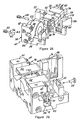
- the palm scanner module 30 incorporates a rubber grip 110 around the crown of the module slightly above a pair of indentations 112 for seating the module in a mounting bracket 114, enabling the module to pivot about a horizontal axis.
- the bracket 114 includes a pair of upstanding supports 116 having spindles 118 for rotatably supporting the module.
- the bracket 114 in turn is mounted on a base 120 that is turreted to a mounting plate 122 and hence is able to rotate about a vertical axis.
- the scanner module 30 can be easily removed from the bracket by lifting with a force sufficient to enable the spindles 118 to slip from the indentations 112.
- the outgoing beam 36 is generated in the scanner 30 by a laser diode or the like, and directed to impinge upon the barcode symbol 32 that ordinarily is positioned a few inches from the front of the scanner. However, other applications may require scanning a target that is at a considerable distance, e.g., 60 feet from the scanner.
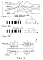
- the outgoing beam 36 is scanned using various patterns to be described later, one being a linear raster as shown in Figures 2A and 2B .
- the user positions the hand-held unit so that the scan pattern traverses the symbol to be read.
- Light reflected from the symbol is received by the unit 30 and detected by a photodetector 44 within the housing.
- Light beam 36 in both directions, passes through a transparent or translucent window 38 that preferably is approximately square in shape to accommodate 2-D as well as 1-D pattern scanning.
- a raster scanning pattern is traversing a 1-D barcode.
- Such a scan pattern may be generated by vertical (or Y-direction) displacement of a linear scan line driven in the X-direction, such as described in U.S. Patent 4,387,297 .
- numerous scan lines traverse the barcode, only one line of scan is necessary for proper decoding since the additional scan lines are redundant and only re-read the same data on a different vertical position of the barcode symbol.
- the raster traverses a 2-D barcode, and is opened vertically to encompass the barcode entirely.
- the 2-D pattern contains many rows of optical elements, it is necessary only that each row be traversed once, as shown, for decoding.
- This "spot” can be developed, and is presented in most visible form, by an oscillating circle, or spiral, pattern shown in Figure 5C .
- Other patterns found suitable for aiming are rosette ( Figures 5A and 5B ), stationary Lissajous ( Figure 5D ), rotating line ( Figure 5E) and rotating Lissajous ( Figure 6 ).
- the line scan pattern of Figure 5E is produced by generating a beam of a relatively short line scan pattern, and rotating the pattern quickly about its center once or after every few scans.
- the scan line may be randomly positioned at pre-determined angles, once or after every few scans, and the angle of rotation about its center of rotation may be controlled in response to signals read produced by light reflected from the symbol.
- the orientation of the barcode may be estimated using a peak detector, to be described later, if the barcode is a 1-D barcode or the orientation may be estimated from the returned digital bar pattern, or DBP, as the scan line is positioned at different angles.
- the scan pattern opens in the exact orientation of the barcode as determined by the peak detector, as shown in Figure 3B , so that the entire barcode will be decoded.
- the ultimate size of the rotating scan line pattern, and the rate at which the pattern opens, is controlled dependent upon barcode attributes, such as type, aspect ratio and size, decoded during the aim mode.
- the barcode may be completely decoded during the aim mode, and if so, a consistency check may be performed during the decoding mode.
- the scan lines In order to cover all possible orientations of the barcode, the scan lines must be capable of rotating through 180 degrees, and preferably the entire symbol will be covered such that at least two scan lines traverse each row of bar patterns during reading.
- the resolution of rotation depends on the aspect ratio and size of the barcode.
- FIGS 10-12 means for detecting when the scan line of Figure 5E is aligned to a barcode are shown.
- the barcodes and scan line are in alignment and out of alignment, respectively.
- the DBP (digital bar pattern) stream corresponding to the scanned barcode is analyzed to find the scan angle at which the energy content of the DBP stream is maximum because the scan line has intersected the most barcode elements.
- the DBP pattern scanned by line 75a has more elements than that of Figure 10B where the barcode has been scanned by a skewed scan line 75b.
- the DBP stream is read and supplied as an analog signal (a) derived from the DBP stream to a high pass filter 70 which produces waveform (b).
- a peak level detector 72 tracks the peak value or envelope of the filtered replication of the DBP stream (see waveform (c)), and the peak value is compared to a prescribed threshold (e) by comparator 74.
- the points at which the envelope and threshold intersect each other develop an output signal (e) having a duration that corresponds to the number of DBP elements spanned by the scan line.
- the duration of the output signal is measured by timer 76, to indicate the number of elements of the DBP stream, and the scan line producing a DBP stream of greatest duration is identified as having the best alignment to the barcode.
- the orientation of the scan line alternatively may be determined more precisely than what is capable using the circuit of Figure 12 by implementing an algorithm wherein the DBP stream is read and scanned for regions bound by a known scan direction synchronizing signal (called "SOS") having the most elements. For example, the orientations between five and ten degrees may have one hundred elements, while all others have fewer. If the scan line is shorter than the barcode, then this region between five and ten degrees, for example, will indicate the general barcode orientation. A more exact orientation can be found by rotating the scan line in a direction that minimizes the total sum of these element widths. Once the exact orientation is found, the scan line length may be increased until a decode occurs. Hence, this approach represents a global search for general barcode orientation, and then a fine tuning step.
- SOS scan direction synchronizing signal
- the circuit of Figure 12 is more immune than the algorithmic approach, as the threshold of comparator 74 may be set to ignore spurious elements due to noise.
- A(t) sin(w 3 t).
- A(t)
- the rotating Lissajous pattern is somewhat inferior for aiming because its visibility is less pronounced than other patterns, but is particularly advantageous insofar as its ability to decode during aiming is the most robust of all the patterns considered.
- Another pattern for aiming found particularly effective is a bright rosette pattern of diameter less than the diameter of rosette to be used for decoding.
- the scanner begins to deflect the light beam with a scan pattern appropriate for decoding the barcode.
- the scan pattern for decode may be the same as for aim, or may be a different pattern or may be the same or different pattern with center of rotation that shifts upon transition between the two modes or during decoding.
- the decode scan pattern which is generated depends upon whether the barcode is found to be a 1-D barcode (when the preferred decode pattern is omni-directional) or a 2-D barcode (when the preferred decode pattern is raster). Pattern switching may be responsive to a second trigger pull, or may occur automatically.
- a rotating Lissajous aiming pattern is directed toward a target having a 2-D barcode, as shown.
- the barcode is partially decoded to determine barcode type and orientation.
- the first row of the barcode may be decoded to determine whether the barcode is a 1-D or 2-D barcode.
- an algorithm may be used that is capable of determining whether the portion read is a portion of a 1-D or 2-D barcode on the basis of code words detected and decoded.
- the scan pattern is changed to a raster pattern, as shown in Figure 4B , necessary for scanning such barcodes.
- the width of the scanning pattern is opened until it at least spans the width of the barcode, and the height is incremented until the entire barcode is decoded.
- the barcode rows encompassed by the scanning pattern will be read, decoded and interpreted to determine whether an entire 2-D barcode symbol has been scanned, as described in U.S. Patent 5,235,167 .
- Each row the bar code will preferably be traversed by at least two scan lines, although only one traversal is necessary.
- the specific pattern produced by the scanner is a pattern that is optimized for a particular classification of indicia and depending on whether the scanner is operating in a portable mode or is mounted in its fixture.
- a scan pattern is deemed to be optimized if it reads and decodes a prescribed pattern in a minimum amount of time, and within reasonable economic constraints.
- the rotational orientation of the scan pattern with respect to barcode is indeterminate.
- the scanner is operated in the aim and shoot mode, with the module 30 separated from the bracket, the scanning pattern may be manually aligned with the barcode.
- the specific pattern produced should be optimized for decoding barcodes of the particular classification of barcode being read.
- a suitable scan pattern is produced for determining classification of the symbol to be read, e.g., whether the symbol is a 1-D or 2-D barcode.
- a rotating Lissajous scanning pattern is selected for its omnidirectionality and robust decoding ability.
- it is determined whether the scanner is in the portable mode or fixed mode of operation (the order of sequence of the first two steps is arbitrary). This may be carried out by detecting the presence of the module 30 in bracket 114 by means of, e.g., a mechanical or magnetic proximity switch in the base of the fixture (not shown in Figures 26A, 26B ), or by a manual switch located on module 30 or elsewhere.
- the scanner is in the fixed mode of operation and arranged to read a barcode symbol.
- the symbol is preliminarily read using the rotating Lissajous, scan pattern to detect the start and stop codes of the barcode, so as to determine whether it is a 1-D or 2-D barcode. If the symbol being scanned is determined to be a 1-D barcode, the scanning pattern will remain defaulted in the form of a rotating Lissajous pattern, as shown in Figure 27 , a pattern that has been determined in accordance with the invention to be optimized for 1-D barcodes. If the symbol is determined to be a 2-D barcode, on the other hand, the scanning pattern is changed to a self-aligning raster, as also shown in Figure 27 .
- a self-aligning raster is a raster that rotates or precesses so as to traverse a 2-D barcode and read it independently of the rotational orientation of the barcode.
- a specific embodiment of self-aligning raster is a precessing raster described in more detail later with reference to Figure 7 .
- the scanner when the scanner is determined to be operating in the portable mode, and the symbol as read during Lissajous scanning is determined to be a 2-D barcode, the scanner produces a raster type scanning pattern.
- This raster is preferably stationary, but may be enhanced to precess or rotate so as to read barcode symbols of diverse rotational orientations.
- scanning is continued in the form of a pattern optimized to read such barcodes, such as a single or rotating scan line, or rotating Lissajous.
- the particular scanning patterns produced for decoding 1-D or 2-D barcodes when the scanner is operated in portable and fixed modes can be varied for specific applications and modules of particular optical characteristics. What is important is that the scanner is adaptive, controlled manually but preferably automatically, to produce decoding scan patterns that are optimized, that is, as robust as practical with respect to the operating mode selected and the classification of indicia being read.
- the scan pattern is also optimized in dependency on whether scanning is carried out by a presentation type (under a scan lamp) or a pass through (supermarket) type reader.
- a presentation type reader an particle carrying a barcode or other symbol to be read is brought to the reader or the reader is brought to the article. Since reading is carried out in very close proximity to the barcode, there is no need for aiming.
- the pass through reader the article bearing a barcode is swiped past a scanning pattern produced by a fixed source of light beams.
- a scanning pattern producing lines that are more sparsely spaced but more often repeated is preferred because it is more likely to traverse the barcode. That is, the faster the swipe, the thicker the barcode should be and hence a scanning pattern, such as a rotating Lissajous pattern, optimized for a relatively thick barcode pattern is preferred.
- the rate of increase of the size of the raster in moving from Figure 4B to Figure 4C is responsively controlled depending upon the size and nature of the barcode.
- the rate at which the scan pattern opens may be controlled to be faster for larger barcodes.
- the size of each increment may be dependent upon the working range of the scanner. For example, very long range scanners, e.g., up to about 60 feet, may require smaller increments so that the patterns do not grown too fast at the end of the working range.
- the preferred Lissajous pattern for decoding is preferably of frequency ratio x/y ranging from 1.1 and 1.3 and rotated at a rate of between 1 to 4 degrees per scan. These numbers are found optimal for scanning highly truncated 1-D barcodes.
- the rotating Lissajous pattern with its sequence of scanning patterns that are successively rationally offset, has been found more robust for decoding than a stationary Lissajous pattern.
- the optimal stationary Lissajous pattern is at a frequency ratio 0.7.
- the optimized rotating Lissajous pattern produces a 17% improvement in decoding efficiency over the stationary Lissajous pattern.
- the frequency ratio is made higher by increasing the slower scan frequency y.
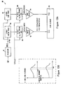
- Single line rotation and scanning is produced, in accordance with the invention, by driving two mirrors (not shown) using the circuit 80 of Figure 13A which corresponds to, but is more detailed than, Figure 8 .
- the two mirrors are mounted on resonant scan elements having relative resonant frequencies at wa and wb, respectively, shown in Figure 13B .
- the circuit 80 implements a processor 82 that estimates the orientation of the barcode based on element counts in the DBP stream and/or start and stop character detection. A scan line will be opened upon the second trigger pull at an angle based on the last detected barcode orientation.
- the processor 82 addresses EEPROM cosine and sine tables 84 and 86 which generate digital data corresponding to amplitudes of the cosine and sine of the prescribed anglers. These digital signals are multiplied by sin(wt), and the product converted to a corresponding analog signal in multiplying digital-to-analog converters (DAC) 88 and 90.
- DAC digital-to-analog converters
- Amplitude control shown herein assumes that the Y-element will be driven somewhat harder than the X-element so as to compensate for any slightly leading resonant peak, as depicted in the amplitude response curves of Figure 13B . Similar compensation may have to be carried out to equalize the phase responses.
- the X-element is leading in phase.
- the phase adjustment is performed by phase adjustment circuits 92 and 94.
- the outputs of the phase adjustments 92, 94 are supplied to the X- and Y-inputs of resonant scan elements 96.
- Resonant scan elements are known in the art. Such elements typically are provided with a flexural strip of Mylar or other material cantilever mounted to a base and supporting a miniature permanent magnet positioned within a coil. The coil is secured to a base, and a scan mirror is attached to the free end of the cantilever mounted flexural strip. By changing the dimensions or flexural characteristics of the cantilever mounted strip, the mass of the strip, the permanent magnet and mirror, or the distribution of mass on the flexural strip, different resonant frequencies can be established.
- the resonant scan element can also be presented as a single element having different resonant frequencies in mutually orthogonal directions, and utilizing a single mirror to perform single line rotation and scanning.
- the circuit 80 of Figure 13A can be implemented to apply drive signals for X- and Y-scanning to the two inputs of the dual-resonance scanning element, as disclosed in the copending application.
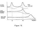
- any Lissajous pattern may be rotated if the two sine functions are replaced by their Lissajous equivalent. If the resonant scan element has the desired equal amplitude and phase responsive at the two sinusoidal components of each drive axis, as illustrated in Figure 16 depicting the frequency response shapes of resonant scan elements for 2-D scanning, then no added compensation for phase and amplitude is required.
- a circuit 98 for developing drive signals for Lissajous pattern rotation shown in Figure 14 and described by equations (3) and (4), comprises a processor 100 addressing sine and cosine EEPROM tables 102 and 104 that produce the sine and cosine values of the angle, in digital form, generated by the processor. These sine and cosine digital values are supplied to multiplying DAC units 106 to produce the analog sine and cosine functions of the above equations.
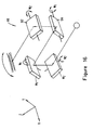
- the four drive signals produced by circuit 98 of Figure 14 may be applied to four resonant elements supporting four reflectors, each oscillating at a single resonant frequency, as shown in Figure 17 and identified by numeral 110.
- a first pair 112, 114 of the mirrors 110 is optically combined as X-axis elements having two resonant frequencies.
- the second pair is arranged as a Y-axis element having two resonant frequencies that match those of the first pair.
- the mirrors may be oriented in either of the configurations of Figures 15A and 15B.
- each mirror pair may be combined on a single resonant element wherein a distinct resonant peak is available for each axis.
- the element hence can be driven at its resonance frequency by the higher frequency w2 and off resonance by the lower frequency w1, but with a larger amplitude and any necessary phase compensation.
- Resonance elements of dual resonant frequency response may be arranged orthogonally to produce the rotatable raster patterns in this case.
- Figures 9A-9D are raster patterns scanning 2-D and 1-D barcodes, respectively, in perfect alignment.
- scanning typically will be somewhat skewed as shown in Figures 9B and 9E .
- 2-D scanning mechanisms tend to be slightly non-linear and will ordinarily produce a somewhat arcuate, or drooped, scan pattern as shown in Figures 9C and 9F , decoding of the barcode is somewhat difficult to achieve when a complete row of barcode is not entirely scanned.
- another aspect of the invention precesses the raster so as to traverse barcode elements that are angularly displaced or are not oriented along a straight line.
- the angle of sweep of each line by the raster scanner is staggered or precessed slightly, so that the light beam sweeps across the barcodes in a zig-zag pattern.
- Precession whereby subsequent scanning patterns are rotationally offset from a previous pattern occurs when the ratio of the X component to the Y component of the scanning pattern is not an integer. In the preferred embodiment, the scan ratio is 1.75:1.
- the Y component frequency is 68.5 scans per second (120 divided by 1.75).
- the scanner can be designed such that the scan ratio is always 1.75:1, although precession alternatively can be achieved by activating the Y frequency scan by a computer driver.
- each row of the bar code will be traversed by two lines of scan, although only a single scan line per row is necessary.
- the resultant zig-zag pattern causes the light beam to sweep the barcode symbols in a plurality of different angles, so that angularly offset lines of barcode up to about thirty degrees of offset can be read by the raster during precession. Similarly, even if the beam emitted by the scanner contains a degree of droop, the precessing raster will scan every barcode line during successive frames.
- the processors 82 of Figure 13A and 100 of Figure 14 are programmed to control the scanner of this invention in the aim and decode modes, either by manual (trigger) operation or automatically as described previously. Programming of the processors will now be described with reference to the flow charts of Figures 18 and 19 .
- Figure 18 represents scanner operation for either 1-D or 2-D barcodes, wherein the trigger must be operated once for aim and a second time for decode.
- Figure 19 describing a 1-D barcode scanning example, the transition between aim and decode modes of operation is automatic. In some cases, the requirement to operate the trigger twice for aim and decode is preferable, to prevent a symbol from being decoded prematurely or decoding a neighboring barcode.
- the scanner awaits a first operation of the manual trigger, and when the trigger has been first depressed, as detected in step 100, the scanner generates the aim mode pattern which, as aforementioned, preferably is an omnidirectional pattern (an omnidirectional pattern is one wherein the scan angle the beam traverses over time is not limited) and may be any suitable scan pattern that is radially symmetric, e.g., not a simple raster pattern, including those shown in Figures 5A-E or Figure 6 ; the oscillating circle or spiral pattern ( Figure 5C ) being best from a standpoint of visibility and the rotating Lissajous pattern being best from the standpoint of preliminary decoding of the barcode (step 102).
- an omnidirectional pattern is one wherein the scan angle the beam traverses over time is not limited
- the scanner now waits for another trigger operation, and when the trigger has been manually operated for the second time, as determined in step 104, an omni-pattern for decoding is generated by the scanner (step 106).
- the aim pattern in the form of a rotating Lissajous for aiming transitions converts to a raster for decoding, and as shown in Figure 4C the aiming pattern is incremented in size (step 108) until the maximum size of the pattern is exceeded (step 110) when the scan pattern is reset in step 112 to increment again.
- step 114 If, however, the barcode has been fully decoded, determined in step 114, before the maximum size of the scan pattern is exceeded, the routine is completed.
- each pattern increment, and the rate at which the increments are generated are preferably controlled in response to data read from the symbol during the aim mode to achieve an optimal rate of Y-direction expansion depending on the number of rows in and height of a label. If the 2-D code is not successfully decoded at step 114, then decoding is continued until either a successful decode has occurred or until a predetermined amount of time, typically on the order of three seconds, has elapsed.
- transition from the aim mode to the decode mode is made automatically, and for this example, the procedure is particularized for scanning a 1-D barcode, although the procedure could be generalized to encompass 2-D barcodes as well.
- step 120 a rotating line pattern (step 122), corresponding to what is shown in Figure 5E, is produced. Alignment of the rotating line pattern and barcode is monitored in step 124, and may optionally be fine tuned in accordance with step 126. Alignment may be performed in accordance with the procedure of Figure 11 and circuit of Figure 12 .
- a second manual operation of the trigger per step 128 is optional. Even if the trigger is not operated at this time, when the decoder has determined the optimum angle at which to emit a decode scan pattern, the pattern is produced (step 130). The line size is incremented (step 132) until it exceeds the length of the barcode (step 134). If the maximum size is exceeded, the size of the scan line is reduced to the minimum size for aiming (step 136) and the process repeats. During the time the length of the scan line is incremented, the barcode is being decoded, in step 138, and when decoding is completed, the routine is terminated.
- the light beam directed toward the symbol to be read is transitioned between first and second scan paths in the aim and decode modes.
- the first and second scan paths may differ from each other by rotation about an axis of rotation, by increase in scan path envelope diameter, by both rotation and envelope diameter increase and by displacement of the center of rotation of the first scan pattern.
- the user can, therefore, simply aim an apparent spot on the barcode, without regard for the barcode's orientation, and then decode it upon the second trigger pull. It is also possible to provide automatic scan line opening without a second trigger pull. However, there is a danger that the scanner may unintentionally scan and decode the wrong barcode.
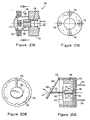
- a scan module 110 supports and oscillates an objective lens 112 that is mounted on a circuit board 114 that also carries four electric coils 116 equally spaced along the four quadrants of the circuit board.
- a support member 118 has a central opening 120 for receiving and retaining a light emitting diode 122 that preferably is a laser diode.
- a permanent magnet 124 At a side of the support 118, opposite the diode 122, is a permanent magnet 124 that interacts with an electromagnetic field produced by the coils 116 when an electric current is applied.
- the circuit board 114 and support 118 are interconnected by four semi-rigid wires 126 that also carry electric current from a driver circuit to the four coils. By changing the connections between the coils, 1-D or 2-D scan patterns may be selectively achieved.
- Wires 126 preferably are tin-soldered to the circuit board 114 and support 118.
- the material of the wires preferably is a phosphor-bronze alloy, although any other material that conducts electricity and provides semi-rigid support of the circuit board 114 and lens 112 with respect to support 118 may be used.
- Magnet 124 is in the form of a ring, and in one embodiment may be magnetized axially.
- the central hole of magnet 124 serves as an aperture stop for the laser beam.
- the permanent magnet 124 may be multiply poled around its circumference.
- the poling of the permanent magnet may be such that there are four poles, with South poles being oriented at 0° and 180° and North poles at 90° and 270° along the circumference.
- the lens and coil assembly will rotate slightly, and hence the semi-rigid wires will begin to form a helix, reducing the distance between the lens 112 and laser beam source 122 to focus the beam.
- the other two coils are energized to oscillate the lens assembly to produce appropriate scanning.
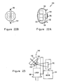
- FIG. 20A and 20B Another embodiment of scanner, shown in Figures 20A and 20B , comprises a casing 130, of bakelite or other suitable material, and of cylindrical configuration. Within the casing 130 is seated a soft iron disk 132 having apertures to accommodate a number of terminals 134 for supplying electric current to an electromagnetic coil 136 positioned on the disk 132. Surrounding the coil 136 within casing 130 is a ring magnet 138 for producing a magnetic field that interacts with the electromagnetic field produced by coil 136. A soft iron core 140 is positioned in the central aperture of the coil 136, and a thin diaphragm 140 of flexible material is seated on the end of magnet 138, as shown, spanning the coil 136 and its core 140. On the outer surface of the diaphragm 140, near the end of core 140 is a thin metal plate 144 of low mass.
- a piece of film 148 Pivotably mounted to the end of casing 130 at 146 is a piece of film 148, preferably made of Mylar.
- a reflector 150 Upon the outer surface of the membrane, at a position in longitudinal alignment with core 140, is a reflector 150.
- the reflector 150, together with its supporting membrane 148, is maintained separated from the diaphragm plate 144 by another piece of film 152, again preferably formed of Mylar.
- the device shown in Figures 20A and 20B is of a type conventionally used as an audio beeper, wherein an audio signal applied to leads 134 produce oscillation of the membrane 142 and its attached plate 144.
- mechanical coupling between reflector 150 and membrane 142 by virtue of Mylar film 152, causes the mirror 150 to oscillate correspondingly, and, if coil 136 is suitably energized, scan.
- FIG. 22A and 22B Another embodiment of a scanning mechanism, in accordance with the invention, is shown in Figures 22A and 22B as 148, wherein 1-D scanning is carried out by a scanning element in the form of a bracket, or tensioner, 150 that is of integral construction, generally C-shaped in configuration and resilient. Spanning the ends of the bracket 150 is a closely spaced, parallel pair of wires 152 maintained taut by the spread of the bracket. Attached to the taut wires 152, and essentially located thereon, are a reflector 154 and permanent magnet 158, secured to the wires by a clamp 156.
- a scanning element in the form of a bracket, or tensioner, 150 that is of integral construction, generally C-shaped in configuration and resilient. Spanning the ends of the bracket 150 is a closely spaced, parallel pair of wires 152 maintained taut by the spread of the bracket. Attached to the taut wires 152, and essentially located thereon, are a reflector 154 and permanent magnet 158, secured to the
- an electromagnetic coil 160 which, when energized, produces an electromagnetic field that interacts with the field of the permanent magnet to oscillate reflector 154 in one direction, for example, the X-direction.
- a separate reflector 162 for deflecting the light beam in the Y-direction, is oscillated by a Y-motor 164.
- FIG. 24 Another embodiment of scanner, shown in Figure 24 , comprises an electromagnetic coil 172 having a central opening into which partially extends and electromagnetic coil 174.
- the coil 172 is rigidly secured to a support member (not shown), and the magnet 174 is resiliently coupled to the same support by means of an arm 176.
- a U-shaped spring 178 is attached to the magnet 174 at one end, and the opposite end of the spring supports an optical element, preferably a reflector 180.
- Electrical leads (not shown) carry an energizing current or drive signal to the coil of electromagnet 174.
- the reflector 180 will oscillate in response to such electromagnet coil signal so as to scan in one or two dimensions, selectively.
- the spring 178 may be made of any suitable flexible materials, such as a leaf spring, a flexible metal coil or a flat bar having sufficient flexibility properties, and may be of a material such as a beryllium-copper alloy.
- the reflector 180 is positioned between a laser beam source and lens assembly 182 and a target (not shown in Figure 24 ). Between the reflector 180 and source 182 is a collector 184 having an opening through which a light beam emitted by the laser source 182 may pass to the reflector 180. The collector is oriented so as to direct incoming light, reflected by reflector 180 and then collector 184, to a photodetector 186.
- the mass of reflector 180 is considerably less than the mass of permanent magnet 174.
- the mass of the mirror is selected to be less than about one-fifth the mass of the magnet, and the angle of vibration of the mirror as shown in Figure 25 , a diagram derived by computer simulation, is about seven times that of the permanent magnet.
- the reflector 180 is capable of 2-D scanning.
- the U-shaped spring 178 which may be formed of a plastic material, such as Mylar or Kapton, the arms of the U-shaped spring 178 and the planar spring 176 may be arranged to vibrate in planes which are orthogonal to each other. Oscillatory forces applied to permanent magnet 174 by the electromagnetic 172 can initiate desired vibrations in both of the springs 178 and 176 by carefully selecting drive signals applied to various terminals of the coil, as discussed in the copending application. Because of the different frequency vibration characteristics of the two springs 178 and 176, each spring will oscillate only at its natural vibration frequency. Hence, when the electromagnetic 172 is driven by a super position signal of high and low frequency components, the U-shaped spring will vibrate at a frequency in the high range of frequencies, and the planar spring 176 will vibrate at a frequency in the low range of frequencies.
- An additional important aspect of the embodiment of Figure 24 is that the laser beam emitted by source 182 impinges the reflector 180 at an angle that is orthogonal to the axis of rotation of the reflector. Hence, the system avoids droop in the 2-D scan pattern that tends to arise when the angle of incidence of the laser beam is non-orthogonal to the reflective surface.
- Figure 24 Another important aspect of Figure 24 is in the folded or "retro" configuration shown, with the laser beam source 182 off axis from that of the beam directed from the reflector 180 to the target.
- the detector field of view follows the laser path to the target by way of collector 184.
- the folded configuration shown is made possible by opening 181 in the collector.
- the retro configuration enables the scanning mechanism to be considerably more compact than heretofore possible.
- bracket 116 may be mounted on an extension tube 124, shown in Figure 26B , so as to offset the module 30 from a support surface and enable tall items to be scanned.
- the invention produces a rotating Lissajous scan pattern or other pattern that is easily seen by the user during aiming on a barcode, and then under manual control or automatically converts to a decode scan that is robust and opens at a rate, and to a size, that depends upon the barcode itself.
- the barcode is a 1-D code
- the decode pattern may be a precessing raster that is able to scan rows that are rotationally misaligned with the scan lines. Scanning is implemented by novel miniature 1-D and 2-D scanning assemblies, as described herein.
- Another form of scanner that can produce the required two-dimensional scanning patterns is of a type implementing a scan element supported by a holder structure mounted on a mylar motor to produce oscillatory movements, the arrangement being mounted on a printed circuit board within a housing that can be manually held.
- the scanning motor and arrangement may be made of components formed essentially of molded plastic material, and utilizing of a mylar leaf spring to limit scan. See, for example, application serial number 07/812,923, filed December 24, 1991 , assigned to the assignee of this invention and incorporated herein by reference.
- Figures 28 to 31 illustrate the preferred scanner module within which the scanning arrangement of Figures 24 and 25 may be incorporated.
- parts of the module already described with reference to Figures 24 and 25 will be given the same reference numerals.
- the preferred scanner module consists of two separate sections: a chassis element 10 and a scan element 12. In Figure 28 , these two sections are shown in exploded form, prior to their securement together during the assembly process.
- the chassis element 10 comprises a chassis 14 which carries the coil 172.
- the coil 172 is secured to a rear wall 16 of the chassis.
- At respective ends of the rear wall there are first and second forwardly-extending side supports 18, 20.
- the forward end of the side support 18 is provided with a vertical slot 22 ( Figure 30 ) into which is placed ( Figure 4 ) the collecting mirror 184 previously referred to.
- the forward part of the other side support 20 is provided with a larger vertical slot or cavity 24 ( Figure 30 ) into which the photodiode assembly 186 ( Figure 31 ) fits.
- the features of the scan element 12 (which is during assembly secured to the chassis element 10) is best seen from a comparison of Figures 28, 29 and 31 .
- the scan element comprises a beryllium-copper bracket generally shown at 26 having a vertical mounting portion 28 in a plane perpendicular to the axis of the coil 172.
- the upper part of the mounting portion is formed with two rearwardly-pointing prongs 30, 32 (not visible in Figure 31 ).
- the spring 178 Secured to the mounting portion 28 is the spring 178, previously mentioned with reference to Figure 24 , which carries the mirror 180.
- first and second hanging brackets 34, 36, best seen in Figures 28 and 29 ). Screwed to these hanging brackets are respective first and second sheets of Mylar film 38, only one of which is visible in Figures 28 to 30 .
- At the top of the Mylar sheets are secured respective hangers 40, 42.
- the scanner module is assembled by bringing the scan element 12 up to the chassis element 10 and using screws 44, 46 to attach the hangers 40, 42 to respective bosses 48, 50 on the chassis side supports 18, 20.
- the relative positioning of the chassis element and the scan element, just prior to their securement together by the screws 44, 46 is shown most clearly in Figure 29 .
- the entire weight of the scan element including the mirror 180, is supported by the hangers 40, 42 and the sheets of Mylar film 36, 38.
- the entire scan element is accordingly free to rock back and forth about a horizontal axis perpendicular to the axis of the coil 172 as the Mylar film flexes.
- a laser beam emanating from the laser beam source and lens assembly 182, passes through the hole 181 in the collector 184, and impinges upon the mirror 180 from which it is reflected via a window 52 to a bar code symbol to be read (not shown).
- Energisation of the coil 172 causes oscillation of the mirror 180 in two directions: a first direction due to flexing of the spring 178 and a second direction due to flexing of the Mylar film 38.
- a variety of scanning patterns can be produced, for example a raster pattern or other types of two-dimensional pattern.
- the lower end of the hanging bracket 34 is located within a channel 54 formed in the side support 18 of the chassis.
- the hanging bracket 34 moves back and forth within the channel 54.
- the Mylar film 34 is prevented from over-flexing by the walls of the channel 54 which act as stops.
- a similar arrangement (not visible in the drawings) is provided on the other side.
- a second level of protection is provided by alignment pins 56, 58, best seen in Figure 28 .
- Each pin comprises a threaded rear head portion 50, a reduced diameter smooth waist portion 62, and a smooth forward head portion 64.
- the waist portion 62 of the pin passes through a hole 68 in the hanging bracket 34, with the forward head portion 64 being received within a correspondingly-sized blind bore 70 within one side of the channel 54.
- the rear head portion 60 of the pin is screwed into and held in place by a threaded bore 66 which opens at its forward end into the channel 54 and at its rearward end into the rear surface of the rear wall 16.
- a threaded bore 66 which opens at its forward end into the channel 54 and at its rearward end into the rear surface of the rear wall 16.
- the diameter of the waist portion 62 of the pin is some 0.02 inches smaller than the diameter of the hole 68 in the hanging bracket. This provides sufficient tolerance for the Mylar to flex slightly during normal operation of the device. However, if the module is dropped the presence of the pin prevents over-stressing and perhaps breaking of the Mylar.
- the alignment pins have a further function of assisting accurate positioning of the scan element 12 with respect to the chassis during assembly.
- the scan element is brought up into approximately the correct position, and the alignment pins are then inserted as shown in Figure 29 .
- the forward head portion 64 is a tight tolerance sliding fit both within the hole 68 in the hanging bracket and in the blind bore 70. This aligns the scan element to the pins and hence to the chassis.
- the scan element is then secured to the chassis, as previously described, using the screws 44, 46.
- the hangers 40, 42 provide a certain amount of adjustability or tolerance in positioning, thereby ensuring that the scan element can be attached to the chassis at the position defied by the alignment pins.
Landscapes
- Physics & Mathematics (AREA)
- Electromagnetism (AREA)
- Engineering & Computer Science (AREA)
- Health & Medical Sciences (AREA)
- General Health & Medical Sciences (AREA)
- Toxicology (AREA)
- Artificial Intelligence (AREA)
- Computer Vision & Pattern Recognition (AREA)
- General Physics & Mathematics (AREA)
- Theoretical Computer Science (AREA)
- Mechanical Optical Scanning Systems (AREA)
- Facsimile Scanning Arrangements (AREA)
Claims (6)
- Ein Scann- bzw. Abtastsystem, welches einen Leser umfasst, der sowohl in einem tragbaren als auch einem fest angebrachten Modus betriebsbereit ist, um (Kenn-) Zeichen zu lesen, und der Folgendes aufweist:Mittel zum Bestimmen, ob sich der Leser in einem fest angebrachten oder einem tragbaren Modus befindet;Mittel zum Scannen der (Kenn-)Zeichen mit einem ursprünglichen Scann- bzw. Abtastmuster, um eine Klassifizierung der (Kenn-)Zeichen zu bestimmen, wobei das ursprüngliche Abtastmuster ein drehendes Lissajous-Abtastmuster ist; undMittel zum Anpassen des ursprünglichen Abtastmusters an ein optimiertes Abtastmuster zum Lesen der (Kenn-)Zeichen basierend auf der detektierten Klassifizierung und dem bestimmten Modus.
- System gemäß Anspruch 1, wobei der Leser eine Lichtquelle zum Erzeugen und Richten eines Lichtstrahls auf die zu lesenden (Kenn-)Zeichen besitzt, und wobei das Mittel zum Scannen bzw. Abtasten den Lichtstrahl über die (Kenn-) Zeichen hinweg streicht, um von diesen reflektiert zu werden, und wobei der Leser einen Lichtsensor zum Aufnehmen des von den (Kenn-)Zeichen reflektierten Lichts besitzt und um darauf ansprechend ein elektrisches Signal zu erzeugen, sowie Mittel zum Umwandeln des elektrischen Signals in Daten, die der Klassifizierung der (Kenn-)Zeichen wiedergeben, und wobei das Anpassungsmittel auf den Sensor anspricht, um den Lichtstrahl zu steuern, so dass dieser die (Kenn-)Zeichen mit dem optimierten Abtastmuster überquert.
- System gemäß Anspruch 2, wobei das Anpassungsmittel in dem fest angebrachten Modus den Lichtstrahl so steuert, dass das optimierte Abtastmuster ein selbstausrichtendes Rastermuster ist, wenn die (Kenn-)Zeichen eine zweidimensionale Strichcode-Klassifizierung besitzen, oder ein Lissajous-Rastermuster, wenn die (Kenn-)Zeichen eine eindimensionale Strichcode-Klassifizierung besitzen.
- System gemäß Anspruch 2, wobei das Anpassungsmittel in dem tragbaren Modus den Lichtstrahl so steuert, dass das optimierte Abtastmuster eine einzelnes oder ein rotierendes Linienabtastmuster ist, wenn die (Kenn-)Zeichen eine eindimensionale Strichcode-Klassifizierung besitzen, oder ein Rastermuster ist, wenn die (Kenn-)Zeichen eine zweidimensionale Strichcode-Klassifizierung besitzen.
- System gemäß Anspruch 1, wobei der Leser ein tragbares Gehäuse mit einem Mittel aufweist, das es einem menschlichen Bediener während eines tragbaren Modus ermöglicht, den Leser zu halten und auf die zu lesenden (Kenn-)Zeichen zu richten, sowie eine stationäre Vorrichtung mit einem Mittel zum Halten des tragbaren Gehäuses des Lesers, wenn dieser nicht von dem Bediener gehalten wird, um es zu ermöglichen, dass der Lichtstrahl in herkömmlicher Weise in Bezug auf die (Kenn-)Zeichen positioniert wird, die durch den Leser in dem fest angebrachten Modus gelesen werden sollen.
- System gemäß Anspruch 5, wobei das Bestimmungsmittel betriebsbereit ist, um zu detektieren, ob das Gehäuse in der Vorrichtung angebracht ist.
Applications Claiming Priority (5)
| Application Number | Priority Date | Filing Date | Title |
|---|---|---|---|
| US08/153,053 US5504316A (en) | 1990-05-08 | 1993-11-17 | Laser scanning system and scanning method for reading 1-D and 2-D barcode symbols |
| US153053 | 1993-11-17 | ||
| US08/326,328 US5581067A (en) | 1990-05-08 | 1994-10-20 | Compact bar code scanning module with shock protection |
| US326328 | 1994-10-20 | ||
| EP94117879A EP0653723B1 (de) | 1993-11-17 | 1994-11-11 | Abtastelement mit Stosschutz |
Related Parent Applications (2)
| Application Number | Title | Priority Date | Filing Date |
|---|---|---|---|
| EP94117879A Division EP0653723B1 (de) | 1993-11-17 | 1994-11-11 | Abtastelement mit Stosschutz |
| EP94117879.0 Division | 1994-11-11 |
Publications (2)
| Publication Number | Publication Date |
|---|---|
| EP1310903A1 EP1310903A1 (de) | 2003-05-14 |
| EP1310903B1 true EP1310903B1 (de) | 2010-07-21 |
Family
ID=26850112
Family Applications (2)
| Application Number | Title | Priority Date | Filing Date |
|---|---|---|---|
| EP03003186A Expired - Lifetime EP1310903B1 (de) | 1993-11-17 | 1994-11-11 | Kompakter Strichcodeabtaster mit Stossschutz |
| EP94117879A Expired - Lifetime EP0653723B1 (de) | 1993-11-17 | 1994-11-11 | Abtastelement mit Stosschutz |
Family Applications After (1)
| Application Number | Title | Priority Date | Filing Date |
|---|---|---|---|
| EP94117879A Expired - Lifetime EP0653723B1 (de) | 1993-11-17 | 1994-11-11 | Abtastelement mit Stosschutz |
Country Status (5)
| Country | Link |
|---|---|
| US (2) | US5581067A (de) |
| EP (2) | EP1310903B1 (de) |
| JP (1) | JPH07254041A (de) |
| CA (1) | CA2136046A1 (de) |
| DE (2) | DE69433196T2 (de) |
Families Citing this family (42)
| Publication number | Priority date | Publication date | Assignee | Title |
|---|---|---|---|---|
| US6575370B1 (en) * | 1990-05-08 | 2003-06-10 | Symbol Technologies, Inc. | Electro-optical scanning assembly with one-piece, oscillatable, focusing/scan element |
| US6742709B2 (en) | 1990-09-11 | 2004-06-01 | Metrologic Instruments, Inc. | Bar code symbol reading system employing electronically-controlled raster-type laser scanner for reading bar code symbols during hands-on and hands-free modes of operation |
| US6227450B1 (en) | 1990-09-11 | 2001-05-08 | Metrologic Instruments, Inc. | Electronically-controlled mechanically-damped off-resonant light beam scanning mechanism and code symbol readers employing the same |
| US6874689B2 (en) * | 1990-09-11 | 2005-04-05 | Metrologic Instruments, Inc. | Laser beam scanning device employing a scanning element having a flexible photo-etched gap region disposed between an anchored base portion and a light beam deflecting portion having a natural frequency of oscillation tuned by the physical dimensions of said flexible photo-etched gap region and forcibly oscillated about a fixed pivot point at an electronically-controlled frequency of oscillation substantially different from said natural resonant frequency of oscillation |
| US6114712A (en) * | 1996-10-09 | 2000-09-05 | Symbol Technologies, Inc. | One piece optical assembly for low cost optical scanner |
| NL9400924A (nl) * | 1994-06-08 | 1996-01-02 | Scantech Bv | Inrichting voor het aftasten van gecodeerde informatie. |
| US6085978A (en) * | 1994-08-17 | 2000-07-11 | Metrologic Instruments, Inc. | Holographic laser scanners of modular construction and method and apparatus for designing and manufacturing the same |
| JP3379837B2 (ja) * | 1994-10-27 | 2003-02-24 | 富士通株式会社 | 光学読取装置 |
| JPH0991368A (ja) | 1995-07-20 | 1997-04-04 | Fujitsu Ltd | 光学読取装置 |
| EP0745950A1 (de) * | 1995-05-30 | 1996-12-04 | Opticon Sensors Europe B.V. | Optisches Abtastgerät zur Erzeugung einer schraubenförmigen Musterabtastung auf einer (zylindrischen) Aussenoberfläche |
| EP0753823A1 (de) * | 1995-07-05 | 1997-01-15 | Opticon Sensors Europe B.V. | Optischer Abtaster zur Erzeugung von Abtastzeilen auf allen Seiten eines Objektes |
| US6811086B1 (en) | 1995-07-20 | 2004-11-02 | Fujitsu Limited | Stand for pivotably mounting an optical reading device |
| US6360949B1 (en) | 1995-10-10 | 2002-03-26 | Symbol Technologies, Inc. | Retro-reflective scan module for electro-optical readers |
| US20020014533A1 (en) | 1995-12-18 | 2002-02-07 | Xiaxun Zhu | Automated object dimensioning system employing contour tracing, vertice detection, and forner point detection and reduction methods on 2-d range data maps |
| US5909302A (en) * | 1996-08-02 | 1999-06-01 | Guissin; Rami | Staring scanner |
| US7028899B2 (en) | 1999-06-07 | 2006-04-18 | Metrologic Instruments, Inc. | Method of speckle-noise pattern reduction and apparatus therefore based on reducing the temporal-coherence of the planar laser illumination beam before it illuminates the target object by applying temporal phase modulation techniques during the transmission of the plib towards the target |
| US7124950B2 (en) * | 1997-09-16 | 2006-10-24 | Metrologic Instruments, Inc. | Bar code symbol reading system employing electronically-controlled raster-type laser scanner for reading bar code symbols during on hands-on and hands-free modes of operation |
| US6592040B2 (en) * | 1998-03-20 | 2003-07-15 | Symbol Technologies, Inc. | Hand-held bar code reader with single printed circuit board |
| US6612496B1 (en) | 2000-03-16 | 2003-09-02 | Symbol Technologies, Inc. | Scan module |
| US6941026B1 (en) | 2000-06-13 | 2005-09-06 | Cognex Corporation | Method and apparatus using intensity gradients for visual identification of 2D matrix symbols |
| US7049585B2 (en) * | 2000-07-27 | 2006-05-23 | Ebara Corporation | Sheet beam-type testing apparatus |
| US6523751B2 (en) * | 2000-12-15 | 2003-02-25 | Yu-Chun Chang | Scanning apparatus |
| JP4364482B2 (ja) | 2002-04-23 | 2009-11-18 | 株式会社キーエンス | 光学シンボル読取装置用光学ユニット |
| US7086596B2 (en) | 2003-01-09 | 2006-08-08 | Hand Held Products, Inc. | Decoder board for an optical reader utilizing a plurality of imaging formats |
| US8002183B2 (en) | 2005-10-20 | 2011-08-23 | Metrologic Instruments, Inc. | Scanner flipper integrity indicator |
| US7614561B2 (en) * | 2005-12-16 | 2009-11-10 | Metrologic Instruments, Inc. | Scanner flipper oscillation frequency detection and adjustment thereof |
| US7832641B2 (en) | 2007-05-24 | 2010-11-16 | Metrologic Instruments, Inc. | Scanner switched to active state by sensed movement in quiescent scanning mechanism |
| US7726575B2 (en) * | 2007-08-10 | 2010-06-01 | Hand Held Products, Inc. | Indicia reading terminal having spatial measurement functionality |
| US8643717B2 (en) * | 2009-03-04 | 2014-02-04 | Hand Held Products, Inc. | System and method for measuring irregular objects with a single camera |
| US8390909B2 (en) | 2009-09-23 | 2013-03-05 | Metrologic Instruments, Inc. | Molded elastomeric flexural elements for use in a laser scanning assemblies and scanners, and methods of manufacturing, tuning and adjusting the same |
| US8294969B2 (en) * | 2009-09-23 | 2012-10-23 | Metrologic Instruments, Inc. | Scan element for use in scanning light and method of making the same |
| US8059324B2 (en) | 2009-09-23 | 2011-11-15 | Metrologic Instruments, Inc. | Scan element for use in scanning light and method of making the same |
| US8748741B2 (en) | 2010-10-25 | 2014-06-10 | Tyco Electronics Corporation | Corrosion resistant multiple tap connectors |
| US8589801B2 (en) * | 2010-11-29 | 2013-11-19 | International Business Machines Corporation | Display screen user identification card for access to secured databases |
| US8915439B2 (en) | 2012-02-06 | 2014-12-23 | Metrologic Instruments, Inc. | Laser scanning modules embodying silicone scan element with torsional hinges |
| WO2013137882A2 (en) * | 2012-03-15 | 2013-09-19 | Optoelectronics Co., Ltd. | Scan unit for a scanning module |
| US8746563B2 (en) | 2012-06-10 | 2014-06-10 | Metrologic Instruments, Inc. | Laser scanning module with rotatably adjustable laser scanning assembly |
| US9984204B2 (en) | 2013-03-15 | 2018-05-29 | Koninklijke Philips N.V. | Monitor/defibrillator with barcode reader or optical character reader |
| US9310609B2 (en) | 2014-07-25 | 2016-04-12 | Hand Held Products, Inc. | Axially reinforced flexible scan element |
| US10146974B2 (en) | 2016-10-12 | 2018-12-04 | Cubic Corporation | Optical scanning for line-of-sight communications to optical tags |
| JP7152147B2 (ja) * | 2017-12-04 | 2022-10-12 | パイオニア株式会社 | 測距装置 |
| US11288469B2 (en) | 2019-12-13 | 2022-03-29 | Zebra Technologies Corporation | Industrial digital barcode reader |
Family Cites Families (21)
| Publication number | Priority date | Publication date | Assignee | Title |
|---|---|---|---|---|
| US4845350B1 (en) * | 1982-01-25 | 1991-04-30 | Narrow-bodied,single-and twin-windowed portable laser scanning head for reading bar code symbols | |
| US5235167A (en) * | 1988-10-21 | 1993-08-10 | Symbol Technologies, Inc. | Laser scanning system and scanning method for reading bar codes |
| US5478997A (en) * | 1988-10-21 | 1995-12-26 | Symbol Technologies, Inc. | Symbol scanning system and method having adaptive pattern generation |
| US5122644A (en) * | 1988-11-17 | 1992-06-16 | Alps Electric Co., Ltd. | Optical code reading device with autofocussing |
| US4962980A (en) * | 1989-01-23 | 1990-10-16 | Metrologic Instruments, Inc. | Laser scanner engine with folded beam path |
| US4971410A (en) * | 1989-07-27 | 1990-11-20 | Ncr Corporation | Scanning and collection system for a compact laser |
| JP2808735B2 (ja) * | 1989-10-25 | 1998-10-08 | 富士通株式会社 | 分離型読取装置 |
| US5206492A (en) * | 1989-10-30 | 1993-04-27 | Symbol Technologies, Inc. | Bar code symbol scanner with reduced power usage to effect reading |
| US5262627A (en) * | 1989-10-30 | 1993-11-16 | Symbol Technologies, Inc. | Scanning arrangement and method |
| US5168149A (en) * | 1989-10-30 | 1992-12-01 | Symbol Technologies, Inc. | Scan pattern generators for bar code symbol readers |
| JP2711158B2 (ja) * | 1989-11-13 | 1998-02-10 | 富士写真フイルム株式会社 | 共振周波数安定化方法および共振型光偏向器 |
| US5115120A (en) * | 1990-06-26 | 1992-05-19 | Photographic Sciences Corporation | Scan modules for bar code readers and in which scan elements are flexurally supported |
| US5268564A (en) * | 1990-08-03 | 1993-12-07 | Symbol Technologies, Inc. | Bar code scanner actuated by detection of scanner motion |
| US5149949A (en) * | 1990-12-10 | 1992-09-22 | Ncr Corporation | Optical scanner with counterrotating reflector elements |
| US5212371A (en) * | 1991-03-01 | 1993-05-18 | Psc, Inc. | Hand held bar code scanner with improved aiming means |
| US5198651A (en) * | 1991-05-03 | 1993-03-30 | Symbol Technologies, Inc. | Laser diode device incorporating structure with integral scanning motor |
| CA2056272C (en) * | 1991-06-14 | 2001-10-16 | Patrick Salatto, Jr. | Combined range laser scanner |
| US5179271A (en) * | 1991-09-19 | 1993-01-12 | Ncr Corporation | Compact optical scan pattern generator for bar code reading systems |
| US5298729A (en) * | 1992-02-14 | 1994-03-29 | Ncr Corporation | Multiple depth of field optical scanner |
| IT1264733B1 (it) * | 1993-11-04 | 1996-10-04 | Datalogic Spa | Dispositivo di lettura o scanner a laser per la lettura di caratteri aventi un diverso grado di riflettenza, in particolare di codici a |
| US5475208A (en) * | 1994-01-27 | 1995-12-12 | Symbol Technologies, Inc. | Barcode scanner having a dead zone reducing system and a multifocal length collector |
-
1994
- 1994-10-20 US US08/326,328 patent/US5581067A/en not_active Expired - Lifetime
- 1994-11-11 EP EP03003186A patent/EP1310903B1/de not_active Expired - Lifetime
- 1994-11-11 DE DE69433196T patent/DE69433196T2/de not_active Expired - Lifetime
- 1994-11-11 EP EP94117879A patent/EP0653723B1/de not_active Expired - Lifetime
- 1994-11-11 DE DE69435305T patent/DE69435305D1/de not_active Expired - Lifetime
- 1994-11-17 JP JP6283700A patent/JPH07254041A/ja active Pending
- 1994-11-17 CA CA002136046A patent/CA2136046A1/en not_active Abandoned
-
1996
- 1996-06-05 US US08/658,383 patent/US5763863A/en not_active Expired - Lifetime
Also Published As
| Publication number | Publication date |
|---|---|
| EP0653723A2 (de) | 1995-05-17 |
| DE69435305D1 (de) | 2010-09-02 |
| US5763863A (en) | 1998-06-09 |
| US5581067A (en) | 1996-12-03 |
| EP0653723A3 (de) | 2000-02-09 |
| DE69433196D1 (de) | 2003-11-06 |
| CA2136046A1 (en) | 1995-05-18 |
| EP0653723B1 (de) | 2003-10-01 |
| DE69433196T2 (de) | 2004-07-29 |
| JPH07254041A (ja) | 1995-10-03 |
| EP1310903A1 (de) | 2003-05-14 |
Similar Documents
| Publication | Publication Date | Title |
|---|---|---|
| EP1310903B1 (de) | Kompakter Strichcodeabtaster mit Stossschutz | |
| US5821521A (en) | Optical scanning assembly with flexible diaphragm | |
| US5705799A (en) | Miniature optical scanning assembly for barcode readers | |
| US5691528A (en) | Scanning system for either hand-held or stationary operation for reading 1-D or 2-D barcodes | |
| US5900617A (en) | Optical scanning module having multiple-sided enclosure | |
| US5486944A (en) | Scanner module for symbol scanning system | |
| US6283372B1 (en) | Electro-optical scanning assembly with conductive flexures | |
| EP0788068B1 (de) | Abtastvorrichtung | |
| US6142379A (en) | Compact bar code scanner with scan mirror jointly movable with drive component | |
| EP0818750B1 (de) | Dünner Abtastermodul | |
| US6360949B1 (en) | Retro-reflective scan module for electro-optical readers | |
| US5373148A (en) | Optical scanners with scan motion damping and orientation of astigmantic laser generator to optimize reading of two-dimensionally coded indicia | |
| US5543610A (en) | Compact bar code scanning arrangement | |
| US6412697B1 (en) | Palm scanner | |
| US5866894A (en) | Electro-optical scanner module having oscillating lens | |
| US5668362A (en) | Light beam scanner with oscillatory scan element | |
| US5479000A (en) | Compact scanning module for reading bar codes | |
| US5988508A (en) | Laser scanning system and scanning method for reading 1-D and 2-D barcode symbols | |
| US5477043A (en) | Scanning arrangement for the implementation of scanning patterns over indicia by driving the scanning elements in different component directions | |
| EP1740994A2 (de) | Synchrone und resonante antriebe zur erzeugung mehrerer abtastlinienmuster für das elektrooptische lesen von indicia | |
| US6575370B1 (en) | Electro-optical scanning assembly with one-piece, oscillatable, focusing/scan element | |
| US6722566B1 (en) | Electro-optical scan module using selectable mirrors | |
| US5925872A (en) | Scanning system for either hand-held or stationary operation for reading 1-D or 2-D barcodes | |
| EP0827102B1 (de) | Kompakte Strichkode-Abtastanordnung | |
| US6959871B1 (en) | Terminal for reading machine-readable indicia and for executing a program |
Legal Events
| Date | Code | Title | Description |
|---|---|---|---|
| PUAI | Public reference made under article 153(3) epc to a published international application that has entered the european phase |
Free format text: ORIGINAL CODE: 0009012 |
|
| AC | Divisional application: reference to earlier application |
Ref document number: 0653723 Country of ref document: EP Kind code of ref document: P |
|
| AK | Designated contracting states |
Designated state(s): DE FR GB IT |
|
| RIN1 | Information on inventor provided before grant (corrected) |
Inventor name: KATZ, JOSEPH Inventor name: GOREN, DAVID P.C/O SYMBOL TECHNOLOGIES INC. Inventor name: LI, YAJUN Inventor name: DVORKIS, PAUL Inventor name: BRIDGELALL, RAJ |
|
| 17P | Request for examination filed |
Effective date: 20031113 |
|
| AKX | Designation fees paid |
Designated state(s): DE FR GB IT |
|
| 17Q | First examination report despatched |
Effective date: 20090710 |
|
| GRAP | Despatch of communication of intention to grant a patent |
Free format text: ORIGINAL CODE: EPIDOSNIGR1 |
|
| GRAS | Grant fee paid |
Free format text: ORIGINAL CODE: EPIDOSNIGR3 |
|
| GRAA | (expected) grant |
Free format text: ORIGINAL CODE: 0009210 |
|
| AC | Divisional application: reference to earlier application |
Ref document number: 0653723 Country of ref document: EP Kind code of ref document: P |
|
| AK | Designated contracting states |
Kind code of ref document: B1 Designated state(s): DE FR GB IT |
|
| REG | Reference to a national code |
Ref country code: GB Ref legal event code: FG4D |
|
| REF | Corresponds to: |
Ref document number: 69435305 Country of ref document: DE Date of ref document: 20100902 Kind code of ref document: P |
|
| PGFP | Annual fee paid to national office [announced via postgrant information from national office to epo] |
Ref country code: FR Payment date: 20101109 Year of fee payment: 17 |
|
| PGFP | Annual fee paid to national office [announced via postgrant information from national office to epo] |
Ref country code: DE Payment date: 20101130 Year of fee payment: 17 |
|
| PGFP | Annual fee paid to national office [announced via postgrant information from national office to epo] |
Ref country code: GB Payment date: 20101022 Year of fee payment: 17 |
|
| PLBE | No opposition filed within time limit |
Free format text: ORIGINAL CODE: 0009261 |
|
| STAA | Information on the status of an ep patent application or granted ep patent |
Free format text: STATUS: NO OPPOSITION FILED WITHIN TIME LIMIT |
|
| PG25 | Lapsed in a contracting state [announced via postgrant information from national office to epo] |
Ref country code: IT Free format text: LAPSE BECAUSE OF FAILURE TO SUBMIT A TRANSLATION OF THE DESCRIPTION OR TO PAY THE FEE WITHIN THE PRESCRIBED TIME-LIMIT Effective date: 20100721 |
|
| 26N | No opposition filed |
Effective date: 20110426 |
|
| REG | Reference to a national code |
Ref country code: DE Ref legal event code: R097 Ref document number: 69435305 Country of ref document: DE Effective date: 20110426 |
|
| GBPC | Gb: european patent ceased through non-payment of renewal fee |
Effective date: 20111111 |
|
| REG | Reference to a national code |
Ref country code: FR Ref legal event code: ST Effective date: 20120731 |
|
| REG | Reference to a national code |
Ref country code: DE Ref legal event code: R119 Ref document number: 69435305 Country of ref document: DE Effective date: 20120601 |
|
| PG25 | Lapsed in a contracting state [announced via postgrant information from national office to epo] |
Ref country code: GB Free format text: LAPSE BECAUSE OF NON-PAYMENT OF DUE FEES Effective date: 20111111 |
|
| PG25 | Lapsed in a contracting state [announced via postgrant information from national office to epo] |
Ref country code: FR Free format text: LAPSE BECAUSE OF NON-PAYMENT OF DUE FEES Effective date: 20111130 |
|
| PG25 | Lapsed in a contracting state [announced via postgrant information from national office to epo] |
Ref country code: DE Free format text: LAPSE BECAUSE OF NON-PAYMENT OF DUE FEES Effective date: 20120601 |