EP1310635A2 - A System and Method for an Engine - Google Patents
A System and Method for an Engine Download PDFInfo
- Publication number
- EP1310635A2 EP1310635A2 EP02102503A EP02102503A EP1310635A2 EP 1310635 A2 EP1310635 A2 EP 1310635A2 EP 02102503 A EP02102503 A EP 02102503A EP 02102503 A EP02102503 A EP 02102503A EP 1310635 A2 EP1310635 A2 EP 1310635A2
- Authority
- EP
- European Patent Office
- Prior art keywords
- camshaft
- phase angle
- crankshaft
- engine
- scheduled
- Prior art date
- Legal status (The legal status is an assumption and is not a legal conclusion. Google has not performed a legal analysis and makes no representation as to the accuracy of the status listed.)
- Withdrawn
Links
Images


Classifications
-
- F—MECHANICAL ENGINEERING; LIGHTING; HEATING; WEAPONS; BLASTING
- F01—MACHINES OR ENGINES IN GENERAL; ENGINE PLANTS IN GENERAL; STEAM ENGINES
- F01L—CYCLICALLY OPERATING VALVES FOR MACHINES OR ENGINES
- F01L1/00—Valve-gear or valve arrangements, e.g. lift-valve gear
- F01L1/02—Valve drive
- F01L1/022—Chain drive
-
- F—MECHANICAL ENGINEERING; LIGHTING; HEATING; WEAPONS; BLASTING
- F01—MACHINES OR ENGINES IN GENERAL; ENGINE PLANTS IN GENERAL; STEAM ENGINES
- F01L—CYCLICALLY OPERATING VALVES FOR MACHINES OR ENGINES
- F01L1/00—Valve-gear or valve arrangements, e.g. lift-valve gear
- F01L1/34—Valve-gear or valve arrangements, e.g. lift-valve gear characterised by the provision of means for changing the timing of the valves without changing the duration of opening and without affecting the magnitude of the valve lift
-
- F—MECHANICAL ENGINEERING; LIGHTING; HEATING; WEAPONS; BLASTING
- F01—MACHINES OR ENGINES IN GENERAL; ENGINE PLANTS IN GENERAL; STEAM ENGINES
- F01L—CYCLICALLY OPERATING VALVES FOR MACHINES OR ENGINES
- F01L2800/00—Methods of operation using a variable valve timing mechanism
-
- F—MECHANICAL ENGINEERING; LIGHTING; HEATING; WEAPONS; BLASTING
- F01—MACHINES OR ENGINES IN GENERAL; ENGINE PLANTS IN GENERAL; STEAM ENGINES
- F01L—CYCLICALLY OPERATING VALVES FOR MACHINES OR ENGINES
- F01L2820/00—Details on specific features characterising valve gear arrangements
- F01L2820/04—Sensors
- F01L2820/041—Camshafts position or phase sensors
Definitions
- the invention relates to a system and method for an engine and in particular to a system and method for controlling dual camshafts in a variable cam timing engine.
- VCT variable cam timing
- each VCT mechanism is utilized to adjust a position of a camshaft (which actuates either an intake valve or exhaust valve or both) with respect to a crankshaft position.
- first and second camshafts associated with first and second VCT mechanisms, respectively, in an engine may not move to the desired phase angle at the same speed.
- the first VCT mechanism may be actuated at a lower pressure that a second VCT mechanism due to a clogged oil line communicating with the first VCT, resulting in slower movement of the first camshaft.
- the first VCT mechanism may "stick" at cold temperatures resulting in slower movement of the first camshaft as compared to the second camshaft of the second VCT mechanism.
- the air charge delivered to first and second cylinder banks, respectively are different.
- the difference in air charge can result in a differing torques being produced by the first and second cylinder banks resulting in undesirable engine shaking and increased engine noise.
- the difference in air charge may result in non-optimal spark timing in one of the cylinder banks resulting in increased engine knock in the cylinder bank.
- the difference in air charge may result in a rich air-fuel mixture being delivered to one of the cylinder banks resulting in decreased fuel economy.
- a method for controlling first and second phase shiftable camshafts in a variable cam timing engine said first and second camshafts controlling air flow communicating with first and second cylinders, respectively, of said engine, said engine further including a crankshaft being driven by first and second pistons within said first and second cylinders, respectively, characterised in that the method comprises determining when said first camshaft is moving toward a first scheduled phase angle with respect to said crankshaft at a faster rate than said second camshaft is moving toward said first scheduled phase angle; and slowing down said first camshaft so that said rate of movement of said first camshaft approaches a rate of movement of said second camshaft toward said first scheduled phase angle.
- the method may further include determining said first scheduled phase angle based on an engine operating parameter.
- Said determining step may include measuring a first phase angle of said first camshaft with respect to said crankshaft, measuring a second phase angle of said second camshaft with respect to said crankshaft and comparing said first phase angle to said second phase angle to determine whether said first camshaft is moving at said faster rate toward said first scheduled phase angle.
- Said step of slowing down said first camshaft may include measuring a phase angle of said second camshaft with respect to said crankshaft, calculating an alternate phase angle of said first camshaft with respect to said crankshaft based on said phase angle of said second camshaft and moving said first camshaft toward said alternate phase angle.
- Said step of calculating said alternate phase angle of said first camshaft may include summing said phase angle of said second camshaft to a predetermined offset phase value.
- Said rate of movement of said first camshaft may be slowed down when a difference between a first phase angle of said first camshaft with respect to said crankshaft and a second phase angle of said second camshaft with respect to said crankshaft exceeds a threshold phase difference.
- a system for controlling first and second phase shiftable camshafts in a variable cam timing engine said first and second camshafts controlling air flow communicating with first and second cylinders, respectively, of said engine, said engine further including a crankshaft being driven by first and second pistons within said first and second cylinders, respectively, characterised in that the system comprises a first sensor generating a first signal indicative of a position of said first camshaft, a second sensor generating a second signal indicative of a position of said second camshaft, a third sensor generating a third signal indicative of a position of said crankshaft; and a controller operably connected to said first, second, and third sensors, said controller configured to determine when said first camshaft is moving toward a first scheduled phase angle with respect to said crankshaft at a faster rate than said second camshaft is moving toward said first scheduled phase angle based on said first, second, and third signals, said controller being further configured to slow down said first camshaft so that said rate of movement
- Said first, second, and third sensors may comprise one of a hall effect sensor, an optical encoder and a variable reluctance sensor.
- a motor vehicle including a system in accordance with said second aspect of the invention.
- an article of manufacture characterised in that the article of manufacture comprises a computer storage medium having a computer program encoded therein for controlling first and second phase shiftable camshafts in a variable cam timing engine, said first and second camshafts controlling air flow communicating with first and second cylinders, respectively, of said engine, said engine further including a crankshaft being driven by first and second pistons within said first and second cylinders, respectively, wherein said computer storage medium comprises code for determining when said first camshaft is moving toward a first scheduled phase angle with respect to said crankshaft at a faster rate than said second camshaft is moving toward said first scheduled phase angle and code for slowing down said first camshaft so that said rate of movement of said first camshaft approaches a rate of movement of said second camshaft toward said first scheduled phase angle.
- Said code for determining when said first camshaft is moving faster than said second camshaft, of said computer storage medium may further include code for determining a first phase angle of said first camshaft with respect to said crankshaft, code for determining a second phase angle of said second camshaft with respect to said crankshaft and code for comparing said first phase angle to said second phase angle to determine that said first camshaft is moving at said faster rate toward said first scheduled phase angle.
- Said code for slowing down said first camshaft, of said computer storage medium may include code for determining a phase angle of said second camshaft with respect to said crankshaft, code for calculating an alternate phase angle of said first camshaft with respect to said crankshaft based on said phase angle of said second camshaft and code for moving said first camshaft toward said alternate phase angle.
- Said code for calculating said alternate phase angle of said computer storage medium may include code for summing said phase angle of said second camshaft to a predetermined phase offset value.
- an automotive vehicle 10 having an engine 12 and a control system 14 is illustrated.
- Engine 12 includes cylinder banks 16, 18 VCT mechanisms 20, 22 and a crankshaft 24.
- each of cylinder banks 16, 18 may have a plurality of cylinders, however, one cylinder of cylinder bank 16 is shown along with VCT mechanism 20 for purposes of simplicity.
- engine 12 further includes a combustion chamber 26, cylinder walls 28, a piston 30, a spark plug 32, an intake manifold 34, an exhaust manifold 36, an intake valve 38, an exhaust valve 40, and a fuel injector 42.
- cylinder bank refers to a related group of cylinders having one or more common characteristics, such as being located proximate one another or having a common emission control device (ECD), intake manifold, and/or exhaust manifold for example. This would include configurations having a group of cylinders on the same side of engine treated as a bank even though these cylinders may not share a common intake or exhaust manifold (i.e., the exhaust manifold could be configured with separate exhaust runners or branches if desired or beneficial). Similarly, cylinder banks can also be defined for in-line cylinder configurations which are within the scope of this invention.
- ECD emission control device
- VCT mechanisms 20, 22 are provided to actuate intake/exhaust valves in cylinder banks 16, 18.
- VCT mechanism 20 is utilized to actuate intake valve 38 and exhaust valve 40 of a cylinder associated with cylinder bank 16 to control air flow entering the cylinder and exhaust gases exiting the cylinder, respectively.
- VCT mechanism 20 cooperates with a camshaft 44, which is shown communicating with rocker arms 48, 50 for variably actuating valves 38, 40.
- the camshaft 44 is directly coupled to housing 52 which forms a toothed cam wheel 54 having teeth 58, 60, 62, 64, 66.
- Housing 52 is hydraulically coupled to an inner shaft (not shown), which is in turn directly linked to camshaft 44 via a timing chain (not shown).
- housing 52 and camshaft 44 rotate at a speed substantially equivalent to the inner camshaft and the inner camshaft rotates at a constant speed ratio to crankshaft 24.
- camshaft 44 to crankshaft 24 can be varied by hydraulic pressure in advance chamber 68 and retard chamber 70.
- hydraulic pressure in advance chamber 68 and retard chamber 70 By allowing high-pressure hydraulic fluid to enter advance chamber 68, the relative relationship between camshaft 44 and crankshaft 24 is advanced.
- intake valve 38 and exhaust valve 40 open and close at a time earlier than normal relative to crankshaft 24.
- VCT mechanism 22 may include like components as illustrated for VCT mechanism 20 and may be hydraulically actuated as discussed above with reference to mechanism 20.
- VCT mechanism 22 includes cam wheel 56 and teeth 72, 74, 76, 78 disposed around the outer surface of the housing of mechanism 22.
- Teeth 58, 60, 64, 66 of the cam wheel 54 are coupled to housing 52 and camshaft 44 and allow for measurement of relative position of camshaft 44 via cam timing sensor 80 which provides signal CAM_POS[1] to controller 84.
- the tooth 62 is used for cylinder identification and, as illustrated, the teeth 58, 60, 64, 66 are evenly spaced around the perimeter of cam wheel 54.
- teeth 72, 74, 76, 78 of cam wheel 56 are coupled to cam wheel 56 and camshaft 46 and allow for measurement of relative position of camshaft 46 via cam timing sensor 82 which provides signal CAM_POS[2] to controller 84.
- Teeth 72, 74, 76, 78 of cam wheel 56 may also be equally spaced around the perimeter of wheel 56 for measurement of camshaft timing.
- controller 84 sends control signal LACT[1] to a conventional solenoid spool valve (not shown) to control the flow of hydraulic fluid either into advance chamber 68, retard chamber 70, or neither of VCT mechanism 20. Similarly, controller 84 sends a control signal LACT[2] to another spool valve (not shown) to control VCT mechanism 22.
- Relative position of camshaft 44 is measured in general terms, using the time, or rotation angle between the rising edge of a PIP signal (explained in greater detail below) and receiving a signal from one of the teeth 58, 60, 64, 66.
- the position of camshaft 46 is measured using the time, or rotation angle between the rising edge of the PIP signal and receiving a signal from one of the teeth 72, 74, 76, 78.
- a measured of cam timing for a camshaft 44 is received four times per revolution, with the extra signal used for cylinder identification.
- combustion chamber 26 communicates with the intake manifold 34 and the exhaust manifold 36 via respective intake and exhaust valves 38, 40.
- the piston 30 is positioned within combustion chamber 26 between cylinder walls 28 and is connected to crankshaft 24. Ignition of an air-fuel mixture within combustion chamber 26 is controlled via spark plug 32 which delivers ignition spark responsive to a signal from a distributorless ignition system (not shown).
- Intake manifold 34 is also shown having fuel injector 42 coupled thereto for delivering fuel in proportion to the pulse width of signals (FPW) from controller 84.
- Fuel is delivered to fuel injector 42 by a conventional fuel system (not shown) including a fuel tank, fuel pump, and fuel rail (now shown).
- a conventional fuel system not shown
- fuel tank, fuel pump, and fuel rail now shown.
- port fuel injection is shown, direct fuel injection could be utilized instead of port fuel injection.
- control system 14 is provided to control the operation of engine 12 and to implement a method for controlling VCT mechanisms 20, 22 in accordance with the present invention.
- Control system 14 includes camshaft position sensors 80, 82, crankshaft position sensor 86, ignition system controller 88, and engine controller 84.
- Camshaft position sensors 80, 82 are provided to generate signals indicative of a position of camshafts 44, 46, respectively.
- Sensors 80, 82 are conventional in the art and may comprise hall-effect sensors, optical encoders, or variable reluctance sensors.
- Sensors 80, 82 are conventional in the art and may comprise hall-effect sensors, optical encoders, or variable reluctance sensors.
- the sensor 80 senses the passing of each tooth and generates respective electric cam pulses or position signals CAM_POS[1] which are received by controller 84.
- teeth 72, 74, 76, 78 pass by sensor 82 which generates respective electric cam pulses or position signals CAM_POS[2] which are received by controller 84.
- the crankshaft position sensor 86 is provided to generate a signal indicative of a position of crankshaft 24.
- Sensor 86 is conventional in the art and may comprise a Hall Effect sensor, an optical sensor, or a variable reluctance sensor.
- a camshaft sprocket 90 is fixed to crankshaft 24 and therefore rotates with crankshaft 24.
- Sprocket 90 may include thirty-five gear teeth 92 spaced ten degrees apart which results in one tooth missing that sensor 86 uses for sensing the position of sprocket 90.
- the sensor 86 generates position signal CS_POS that is transmitted to ignition system controller 88.
- Controller 88 converts the signal CS_POS into the PIP signal which is then transmitted to engine controller 84.
- a PIP pulse occurs at evenly spaced rotational intervals of crankshaft 24 with one pulse per cylinder per engine cylinder cycle. This series of pulses comprise the PIP signal.
- the engine controller 84 is provided to implement the method for controlling VCT mechanisms 20, 22 and in particular, for controlling the position of camshafts 44, 46. Further, controller 84 is provided to compare signal CAM_POS[1] to signal PIP to determine a relative position (i.e., phase angle) of camshaft 44 with respect to crankshaft 24. Similarly, controller 84 compares signal CAM_POS[2] to signal PIP to determine a relative position of camshaft 46 with respect to crankshaft 24.
- controller 84 includes a CPU 94 and a computer readable storage media comprising nonvolatile and volatile storage in a read-only memory (ROM) 96 and a random-access memory (RAM) 98.
- the computer readable media may be implemented using any of a number of known memory devices such as PROMs, EPROMs, EEPROMs, flash memory or any other electric, magnetic, optical or combination memory device capable of storing data, some of which represent executable instructions, used by microprocessor 94 in controlling engine 12.
- the microprocessor 94 communicates with various sensors and actuators (discussed above) via an input/output (I/O) interface 100.
- I/O input/output
- the present invention could utilize more than one physical controller to provide engine/vehicle control depending upon the particular application.
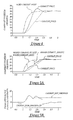
- a scheduled camshaft position signal (Sched_camshaft_angle) for both camshafts 44, 46 is shown.
- controller 84 is requesting that both camshafts 44, 46 move from a relative position of 0° to 40° with respect to crankshaft 24.
- the signal Camshaft_pos[1] represents the movement of camshaft 44
- signal Camshaft_pos[2] represents the movement of camshaft 46.
- the camshaft 44 is moving faster toward the desired phase angle than the camshaft 46.
- T 1.35 seconds
- the phase difference between camshafts 44, 46 equals approximately 21°.
- this phase difference can result in differing torques being produced by cylinder banks 16, 18 resulting in undesirable torque fluctuations and increased engine noise.
- Desired_camshaft_angle[1] represents a commanded position of camshaft 44 over time toward a desired phase angle with respect to crankshaft 24.
- Desired_camshaft_angle[2] represents a commanded position of camshaft 46 over time toward a desired phase angle with respect to crankshaft 24.
- controller 84 determines that crankshaft 24 is moving toward the desired phase angle at a faster rate than crankshaft 24.
- controller 84 decreases the value Desired_camshaft_angle[1] to slow movement of the faster camshaft 44.
- the commanded position signal Desired__camshaft_angle[2] is not adjusted by the inventive method and corresponds to the calculated Sched_camshaft_angle signal.
- the rate of movement of the faster crankshaft 24 approaches the rate of movement of the slower crankshaft 24 resulting in equivalent torques being produced in both cylinder banks 16, 18.
- undesirable torque fluctuations and engine noise is reduced and/or eliminated.
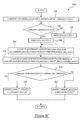
- a step 104 determines a scheduled camshaft phase angle (Sched_camshaft_angle) based on engine operating parameters.
- controller 84 may utilize a throttle position, engine speed, barometric pressure, air charge temperature, and coolant temperature to determine a scheduled camshaft phase angle from a lookup table.
- controller 84 may use an accelerator pedal position and a vehicle speed to determine the schedule camshaft phase angle from a lookup table.
- controller 84 determines the current position (Camshaft_pos[1]) of camshaft 44, based on the signal CAM_POS[1] and the signal PIP.
- controller 84 determines the current position (Camshaft_pos[2]) of camshaft 46 based on the signal CAM_POS[2] and the signal PIP.
- controller 84 simultaneously executes steps 110, 112 for controlling camshaft 44 and steps 114, 116 for controlling camshaft 46.
- the step 110 determines a desired camshaft phase angle (Desired_camshaft_angle[1]) for camshaft 44.
- step 122 a determination is made as to whether Camshaft_difference[1] is greater than or equal to zero. If the answer to step 122 equals "Yes" indicating camshaft 44 is being advanced from a present position, a step 124 sets the value Direction_sign[1] equal to one. Otherwise, camshaft 44 is being retarded from a present position and a step 126 sets the value Direction_sign[1] equal to negative one.
- Alt_camshaft_angle[1] for camshaft 44 corresponds to the position of the camshaft 46 plus an offset.
- Alt_camshaft_angle [1] will only be used to control camshaft 44 if a phase difference between camshafts 44, 46 exceeds a threshold phase difference.
- Camshaft _ bank _ difference [1] Direction _ sign [1]* ( Camshaft _ pos [1] - Camshaft _ pos [2])
- Camshaft_bank_difference[1] is greater than a predetermined value, such zero for example, it indicates that camshaft 44 is moving at a faster speed than camshaft 46 toward the scheduled camshaft phase angle (Sched_camshaft_angle).
- Camshaft_bank_difference [1] when Camshaft_bank_difference [1] is less than the predetermined threshold value, it indicates that camshaft 44 is moving at a slower speed than camshaft 46 toward the scheduled camshaft phase angle (Sched_camshaft_angle).
- step 132 a determination is made as to whether Camshaft_bank_difference[1] is greater than a value Camshaft_diff_threshold.
- the Camshaft_diff_threshold may be equal to a constant value such as 4° for example.
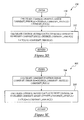
- step 112 the camshaft 44 is moved to a position represented by the value Desired_camshaft_angle[1].
- Desired_camshaft_angle[1] the value Desired_camshaft_angle[1].
- control signal LACT[1] is calculated to move camshaft 44 to Desired_camshaft_angle[1].
- the signal LACT[1] is calculated as a function of the camshaft position error using the following equation:
- step 142 the method 138 is ended.
- steps 114, 116 are utilized for controlling the position of camshaft 46.
- step 114 a desired camshaft phase angle (Desired_camshaft_angle[2]) is determined for camshaft 46.
- step 148 a determination is made as to whether Camshaft_difference[2] is greater than or equal to zero. If the answer to step 148 equals "Yes" indicating camshaft 46 is being advanced from its present position, a step 150 sets the value Direction_sign[2] equal to one. Otherwise, camshaft 46 is being retarded from a present position and a step 152 sets the value Direction_sign[1] equal to negative one .
- the value Alt_camshaft_angle [2] for camshaft 46 therefore corresponds to the position of camshaft 44 plus an offset.
- Camshaft _bank _ difference [2] Direction _ sign [2] * ( Camshaft _ pos [1] - Camshaft _ pos [2])
- Camshaft_bank_difference[2] When Camshaft_bank_difference[2] is greater than a predetermined value, it indicates that camshaft 46 is moving at a faster speed than camshaft 44 toward the scheduled camshaft phase angle (Sched_camshaft_angle). Alternately, when Camshaft_bank_difference [2] is less than the predetermined value, it indicates that camshaft 46 is moving at a slower speed than camshaft 44 toward the scheduled camshaft phase angle (Sched_camshaft_angle).
- step 158 a determination is made as to whether Camshaft_bank_difference[2] is greater than the value Camshaft_diff_threshold.
- the Camshaft_diff_threshold may be equal to a constant value such as 4° for example.
- step 116 After either of steps 160, 162, the method advances to step 116.
- step 116 the camshaft 46 is moved to a position represented by the value Desired_camshaft_angle[2].
- Desired_camshaft_angle[2] the value Desired_camshaft_angle[2].
- control signal LACT[2] is calculated to move camshaft 46 to Desired_camshaft_angle[2].
- the signal LACT[2] is calculated as a function of the camshaft position error using the following equation:
- step 168 the method 164 is ended.
- the control system 14 and method 102 for controlling camshafts 44, 46 of VCT mechanisms 20, 22, respectively, provide a substantial advantage over conventional systems and methods.
- the system 14 and method 102 slows down the movement of the faster camshaft so that the camshafts 44, 46 move at approximately the same speed toward a desired phase angle.
- the synchronous movement results in an equal air charge being provided to first and second cylinder banks during the camshaft movement which reduces engine torque fluctuations and engine noise.
- a system and method for controlling first and second camshafts in a variable cam timing engine are disclosed.
- the inventive method includes determining when the first camshaft is moving toward a first scheduled phase angle with respect to the crankshaft at a faster rate than the second camshaft is moving toward the first scheduled phase angle.
- the method further includes slowing down the first camshaft so that the rate of movement of the first camshaft approaches a rate of movement of the second camshaft toward the first scheduled phase angle.
- the system includes a first sensor generating a first signal indicative of a position of the first camshaft.
- the system further includes a second sensor generating a second signal indicative of a position of the second camshaft.
- the system further includes a third sensor generating a third signal indicative of a position of the crankshaft.
- the system further includes a controller operably connected to the first, second, and third sensors.
- the controller is configured to determine when the first camshaft is moving toward a first scheduled phase angle with respect to the crankshaft at a faster rate than the second camshaft is moving toward the first scheduled phase angle based on the first, second, and third signals.
- the controller is configured to slow down the first camshaft so that the rate of movement of the first camshaft approaches the rate of movement of the second camshaft toward the first scheduled phase angle.
- the inventive system and method for controlling the first and second camshafts solves the problem of engine torque fluctuations during movement of the camshafts.
- the inventive system and method slows down the movement of the faster camshaft so that the first and second camshafts move at approximately the same speed toward a desired phase angle.
- the synchronous movement results in an equal air charge being provided to first and second cylinder banks during the dual camshaft movement which reduces the engine torque fluctuations.
Landscapes
- Engineering & Computer Science (AREA)
- Mechanical Engineering (AREA)
- General Engineering & Computer Science (AREA)
- Combined Controls Of Internal Combustion Engines (AREA)
- Output Control And Ontrol Of Special Type Engine (AREA)
- Valve Device For Special Equipments (AREA)
Abstract
Description
Camshaft_pos[1] represents the current position of
Claims (10)
- A method for controlling first and second phase shiftable camshafts (44, 46) in a variable cam timing engine (12) said first and second camshafts (44, 46) controlling air flow communicating with first and second cylinders, respectively, of said engine (12), said engine (12) further including a crankshaft (24) being driven by first and second pistons (30) within said first and second cylinders, respectively, characterised in that the method comprises determining when said first camshaft (44) is moving toward a first scheduled phase angle with respect to said crankshaft (24) at a faster rate than said second camshaft (46) is moving toward said first scheduled phase angle; and slowing down said first camshaft (44) so that said rate of movement of said first camshaft (44) approaches a rate of movement of said second camshaft (46) toward said first scheduled phase angle.
- A method as claimed in claim 1 further including determining said first scheduled phase angle based on an engine operating parameter.
- A method as claimed in claim 1 or in claim 2 wherein said determining step includes measuring a first phase angle of said first camshaft (44) with respect to said crankshaft (24), measuring a second phase angle of said second camshaft (46) with respect to said crankshaft (24) and comparing said first phase angle to said second phase angle to determine whether said first camshaft (44) is moving at said faster rate toward said first scheduled phase angle.
- A method as claimed in any of claims 1 to 3 wherein said step of slowing down said first camshaft (44) includes measuring a phase angle of said second camshaft (46) with respect to said crankshaft (24), calculating an alternate phase angle of said first camshaft (44) with respect to said crankshaft (24) based on said phase angle of said second camshaft (46) and moving said first camshaft (44) toward said alternate phase angle.
- A method as claimed in claim 4 wherein said step of calculating said alternate phase angle of said first camshaft (44) includes summing said phase angle of said second camshaft (46) to a predetermined offset phase value.
- A method as claimed in any of claims 1 to 5 wherein said rate of movement of said first camshaft (44) is slowed down when a difference between a first phase angle of said first camshaft (44) with respect to said crankshaft (24) and a second phase angle of said second camshaft (46) with respect to said crankshaft (24) exceeds a threshold phase difference.
- A system (14) for controlling first and second phase shiftable camshafts (44, 46) in a variable cam timing engine (12), said first and second camshafts (44, 46) controlling air flow communicating with first and second cylinders, respectively, of said engine (12), said engine (12) further including a crankshaft (24) being driven by first and second pistons (30) within said first and second cylinders, respectively, characterised in that the system (14) comprises a first sensor (80) generating a first signal indicative of a position of said first camshaft (44), a second sensor (82) generating a second signal indicative of a position of said second camshaft (46), a third sensor (86) generating a third signal indicative of a position of said crankshaft (24) and a controller (84) operably connected to said first, second, and third sensors (80, 82 and 86), said controller (84) configured to determine when said first camshaft (44) is moving toward a first scheduled phase angle with respect to said crankshaft (24) at a faster rate than said second camshaft (46) is moving toward said first scheduled phase angle based on said first, second, and third signals, said controller (84) being further configured to slow down said first camshaft (44) so that said rate of movement of said first camshaft (44) approaches said rate of movement of said second camshaft (46) toward said first scheduled phase angle.
- A system as claimed in claim 7 wherein said first, second, and third sensors (80, 82 and 86) comprise one of a hall effect sensor, an optical encoder, or a variable reluctance sensor.
- A motor vehicle (10) including a system (14) as claimed in claim 7 or in claim 8.
- An article of manufacture (84) characterised in that the article of manufacture (84) comprises a computer storage medium (94, 96, 98) having a computer program encoded therein for controlling first and second phase shiftable camshafts (44, 46) in a variable cam timing engine (12), said first and second camshafts (44, 46) controlling air flow communicating with first and second cylinders, respectively, of said engine (12), said engine (12) further including a crankshaft (24) being driven by first and second pistons (30) within said first and second cylinders, respectively, wherein said computer storage medium comprises code for determining when said first camshaft (44) is moving toward a first scheduled phase angle with respect to said crankshaft (24) at a faster rate than said second camshaft (46) is moving toward said first scheduled phase angle and code for slowing down said first camshaft (44) so that said rate of movement of said first camshaft (44) approaches a rate of movement of said second camshaft (46) toward said first scheduled phase angle.
Applications Claiming Priority (2)
| Application Number | Priority Date | Filing Date | Title |
|---|---|---|---|
| US36045 | 1993-03-23 | ||
| US10/036,045 US6647335B2 (en) | 2001-11-09 | 2001-11-09 | System and method for controlling dual camshafts in a variable cam timing engine |
Publications (2)
| Publication Number | Publication Date |
|---|---|
| EP1310635A2 true EP1310635A2 (en) | 2003-05-14 |
| EP1310635A3 EP1310635A3 (en) | 2006-02-15 |
Family
ID=21886289
Family Applications (1)
| Application Number | Title | Priority Date | Filing Date |
|---|---|---|---|
| EP02102503A Withdrawn EP1310635A3 (en) | 2001-11-09 | 2002-10-27 | A System and Method for an Engine |
Country Status (2)
| Country | Link |
|---|---|
| US (1) | US6647335B2 (en) |
| EP (1) | EP1310635A3 (en) |
Cited By (1)
| Publication number | Priority date | Publication date | Assignee | Title |
|---|---|---|---|---|
| EP1568860A1 (en) * | 2004-02-26 | 2005-08-31 | Hitachi, Ltd. | Variable valve operating control apparatus for internal combustion engine and control method thereof |
Families Citing this family (3)
| Publication number | Priority date | Publication date | Assignee | Title |
|---|---|---|---|---|
| DE10047819A1 (en) * | 2000-09-27 | 2002-04-18 | Volkswagen Ag | Method for the simultaneous adjustment of camshafts of different cylinder banks of an internal combustion engine |
| US6842691B2 (en) * | 2002-04-15 | 2005-01-11 | Ford Global Technologies, Llc | Cam synchronization algorithm for engine with variable cam timing |
| JP2007530872A (en) * | 2004-03-29 | 2007-11-01 | サウスウエスト リサーチ インスティテュート | Engine crankshaft position recognition and tracking method applicable to cam and crankshaft signals with arbitrary patterns |
Family Cites Families (6)
| Publication number | Priority date | Publication date | Assignee | Title |
|---|---|---|---|---|
| US5245968A (en) | 1992-08-04 | 1993-09-21 | Ford Motor Company | System to determine cam phase and cylinder identification for a variable cam timing engine |
| US5548995A (en) * | 1993-11-22 | 1996-08-27 | Ford Motor Company | Method and apparatus for detecting the angular position of a variable position camshaft |
| JP3696261B2 (en) * | 1993-11-29 | 2005-09-14 | 株式会社デンソー | Valve timing control device having cylinder discrimination function |
| JP3036394B2 (en) * | 1995-03-31 | 2000-04-24 | トヨタ自動車株式会社 | Valve timing control device for internal combustion engine |
| JP4040779B2 (en) * | 1998-12-25 | 2008-01-30 | ヤマハ発動機株式会社 | Engine valve timing control device and valve timing control method |
| US6219611B1 (en) | 1999-10-18 | 2001-04-17 | Ford Global Technologies, Inc. | Control method for engine having multiple control devices |
-
2001
- 2001-11-09 US US10/036,045 patent/US6647335B2/en not_active Expired - Lifetime
-
2002
- 2002-10-27 EP EP02102503A patent/EP1310635A3/en not_active Withdrawn
Cited By (2)
| Publication number | Priority date | Publication date | Assignee | Title |
|---|---|---|---|---|
| EP1568860A1 (en) * | 2004-02-26 | 2005-08-31 | Hitachi, Ltd. | Variable valve operating control apparatus for internal combustion engine and control method thereof |
| US7011055B2 (en) | 2004-02-26 | 2006-03-14 | Hitachi, Ltd. | Variable valve operating control apparatus for internal combustion engine and control method thereof |
Also Published As
| Publication number | Publication date |
|---|---|
| US6647335B2 (en) | 2003-11-11 |
| US20030093213A1 (en) | 2003-05-15 |
| EP1310635A3 (en) | 2006-02-15 |
Similar Documents
| Publication | Publication Date | Title |
|---|---|---|
| US7398762B2 (en) | Vehicle control system | |
| RU2618718C2 (en) | Motor method (versions) | |
| US7077085B2 (en) | Variable valve control system and method for multi-cylinder internal combustion engine | |
| US10316765B2 (en) | Control device and control method for internal combustion engine | |
| US7290527B2 (en) | Vehicle control system | |
| US6650992B2 (en) | System and method for selecting a camshaft in an engine having dual camshafts | |
| US9260986B2 (en) | Oil pressure scheduling based on engine acceleration | |
| US20060112927A1 (en) | Engine method | |
| EP1318284B1 (en) | System and method for controlling a variable displacement engine | |
| EP1178199B1 (en) | System and method for mixture preparation control of an internal combustion engine | |
| JP2006257958A (en) | Cam phase sensor, variable valve timing mechanism control device, and variable valve timing mechanism control method | |
| US6842691B2 (en) | Cam synchronization algorithm for engine with variable cam timing | |
| EP1418329B1 (en) | A method and system for controlling an engine | |
| US7082923B2 (en) | Idling speed control system and method | |
| US7779802B2 (en) | Simulated cam position for a V-type engine | |
| US6647335B2 (en) | System and method for controlling dual camshafts in a variable cam timing engine | |
| US20120316758A1 (en) | Engine control apparatus | |
| JPH08270469A (en) | Valve timing control device for internal combustion engine | |
| JP5257400B2 (en) | Control device for internal combustion engine | |
| JP2008274822A (en) | Control device for internal combustion engine | |
| JP2007127100A (en) | Control device for internal combustion engine | |
| WO2019187645A1 (en) | Control device for internal combustion engine | |
| JPS62135665A (en) | Device for controlling ignition timing of internal combustion engine |
Legal Events
| Date | Code | Title | Description |
|---|---|---|---|
| PUAI | Public reference made under article 153(3) epc to a published international application that has entered the european phase |
Free format text: ORIGINAL CODE: 0009012 |
|
| AK | Designated contracting states |
Designated state(s): AT BE BG CH CY CZ DE DK EE ES FI FR GB GR IE IT LI LU MC NL PT SE SK TR |
|
| AX | Request for extension of the european patent |
Extension state: AL LT LV MK RO SI |
|
| PUAL | Search report despatched |
Free format text: ORIGINAL CODE: 0009013 |
|
| AK | Designated contracting states |
Kind code of ref document: A3 Designated state(s): AT BE BG CH CY CZ DE DK EE ES FI FR GB GR IE IT LI LU MC NL PT SE SK TR |
|
| AX | Request for extension of the european patent |
Extension state: AL LT LV MK RO SI |
|
| 17P | Request for examination filed |
Effective date: 20060624 |
|
| AKX | Designation fees paid |
Designated state(s): DE GB |
|
| 17Q | First examination report despatched |
Effective date: 20060927 |
|
| STAA | Information on the status of an ep patent application or granted ep patent |
Free format text: STATUS: THE APPLICATION IS DEEMED TO BE WITHDRAWN |
|
| 18D | Application deemed to be withdrawn |
Effective date: 20080829 |