JP3696261B2 - Valve timing control device having cylinder discrimination function - Google Patents
Valve timing control device having cylinder discrimination function Download PDFInfo
- Publication number
- JP3696261B2 JP3696261B2 JP29851493A JP29851493A JP3696261B2 JP 3696261 B2 JP3696261 B2 JP 3696261B2 JP 29851493 A JP29851493 A JP 29851493A JP 29851493 A JP29851493 A JP 29851493A JP 3696261 B2 JP3696261 B2 JP 3696261B2
- Authority
- JP
- Japan
- Prior art keywords
- pulse
- cam
- cylinder
- angle
- signal
- Prior art date
- Legal status (The legal status is an assumption and is not a legal conclusion. Google has not performed a legal analysis and makes no representation as to the accuracy of the status listed.)
- Expired - Lifetime
Links
Images


Classifications
-
- F—MECHANICAL ENGINEERING; LIGHTING; HEATING; WEAPONS; BLASTING
- F02—COMBUSTION ENGINES; HOT-GAS OR COMBUSTION-PRODUCT ENGINE PLANTS
- F02D—CONTROLLING COMBUSTION ENGINES
- F02D13/00—Controlling the engine output power by varying inlet or exhaust valve operating characteristics, e.g. timing
- F02D13/02—Controlling the engine output power by varying inlet or exhaust valve operating characteristics, e.g. timing during engine operation
- F02D13/0203—Variable control of intake and exhaust valves
- F02D13/0215—Variable control of intake and exhaust valves changing the valve timing only
- F02D13/0219—Variable control of intake and exhaust valves changing the valve timing only by shifting the phase, i.e. the opening periods of the valves are constant
-
- F—MECHANICAL ENGINEERING; LIGHTING; HEATING; WEAPONS; BLASTING
- F01—MACHINES OR ENGINES IN GENERAL; ENGINE PLANTS IN GENERAL; STEAM ENGINES
- F01L—CYCLICALLY OPERATING VALVES FOR MACHINES OR ENGINES
- F01L1/00—Valve-gear or valve arrangements, e.g. lift-valve gear
- F01L1/34—Valve-gear or valve arrangements, e.g. lift-valve gear characterised by the provision of means for changing the timing of the valves without changing the duration of opening and without affecting the magnitude of the valve lift
- F01L1/344—Valve-gear or valve arrangements, e.g. lift-valve gear characterised by the provision of means for changing the timing of the valves without changing the duration of opening and without affecting the magnitude of the valve lift changing the angular relationship between crankshaft and camshaft, e.g. using helicoidal gear
-
- F—MECHANICAL ENGINEERING; LIGHTING; HEATING; WEAPONS; BLASTING
- F02—COMBUSTION ENGINES; HOT-GAS OR COMBUSTION-PRODUCT ENGINE PLANTS
- F02D—CONTROLLING COMBUSTION ENGINES
- F02D13/00—Controlling the engine output power by varying inlet or exhaust valve operating characteristics, e.g. timing
- F02D13/02—Controlling the engine output power by varying inlet or exhaust valve operating characteristics, e.g. timing during engine operation
- F02D13/0223—Variable control of the intake valves only
- F02D13/0234—Variable control of the intake valves only changing the valve timing only
- F02D13/0238—Variable control of the intake valves only changing the valve timing only by shifting the phase, i.e. the opening periods of the valves are constant
-
- F—MECHANICAL ENGINEERING; LIGHTING; HEATING; WEAPONS; BLASTING
- F01—MACHINES OR ENGINES IN GENERAL; ENGINE PLANTS IN GENERAL; STEAM ENGINES
- F01L—CYCLICALLY OPERATING VALVES FOR MACHINES OR ENGINES
- F01L2201/00—Electronic control systems; Apparatus or methods therefor
-
- F—MECHANICAL ENGINEERING; LIGHTING; HEATING; WEAPONS; BLASTING
- F02—COMBUSTION ENGINES; HOT-GAS OR COMBUSTION-PRODUCT ENGINE PLANTS
- F02B—INTERNAL-COMBUSTION PISTON ENGINES; COMBUSTION ENGINES IN GENERAL
- F02B2275/00—Other engines, components or details, not provided for in other groups of this subclass
- F02B2275/18—DOHC [Double overhead camshaft]
-
- F—MECHANICAL ENGINEERING; LIGHTING; HEATING; WEAPONS; BLASTING
- F02—COMBUSTION ENGINES; HOT-GAS OR COMBUSTION-PRODUCT ENGINE PLANTS
- F02D—CONTROLLING COMBUSTION ENGINES
- F02D41/00—Electrical control of supply of combustible mixture or its constituents
- F02D41/0002—Controlling intake air
- F02D2041/001—Controlling intake air for engines with variable valve actuation
-
- Y—GENERAL TAGGING OF NEW TECHNOLOGICAL DEVELOPMENTS; GENERAL TAGGING OF CROSS-SECTIONAL TECHNOLOGIES SPANNING OVER SEVERAL SECTIONS OF THE IPC; TECHNICAL SUBJECTS COVERED BY FORMER USPC CROSS-REFERENCE ART COLLECTIONS [XRACs] AND DIGESTS
- Y02—TECHNOLOGIES OR APPLICATIONS FOR MITIGATION OR ADAPTATION AGAINST CLIMATE CHANGE
- Y02T—CLIMATE CHANGE MITIGATION TECHNOLOGIES RELATED TO TRANSPORTATION
- Y02T10/00—Road transport of goods or passengers
- Y02T10/10—Internal combustion engine [ICE] based vehicles
- Y02T10/12—Improving ICE efficiencies
Description
【0001】
【産業上の利用分野】
この発明は、多気筒の内燃機関にあって、それら気筒の別を判別する機能と同内燃機関の吸気バルブや排気バルブの開閉タイミングを適正に制御する機能とを併せ具える気筒判別機能を有するバルブタイミング制御装置に関する。
【0002】
【従来の技術】
従来、多気筒エンジン(内燃機関)の気筒判別を行う装置として、例えば図8に示されるような装置が知られている。
【0003】
はじめに、この図8に示す気筒判別装置についてその概要を説明する。
同図8に示されるように、こうした気筒判別装置では通常、エンジンクランク軸1の回転を伝達機構2により吸気カム軸3及び排気カム軸4に伝達し、それら任意のカム軸の特定の回転角度を基準としたクランク軸1の回転角度を検出することによって気筒の判別を実現している。
【0004】
ここで、伝達機構2は、クランク軸1に係合されたクランクプーリ21、タイミングベルト22、吸気カム軸3に係合された吸気カムプーリ23、及び排気カム軸4に係合された排気カムプーリ24等によって形成されている。該伝達機構2は通常、これらクランクプーリ21、タイミングベルト22、吸気カムプーリ23、及び排気カムプーリ24等を通じて、クランク軸1とカム軸3及び4とが2対1の回転角度に維持されるよう、その伝達係数が設定されている。なお、吸気カム軸3に設けられているカム31は、同カム軸3の回動に基づいて吸気バルブ32を開閉駆動し、排気カム軸4に設けられているカム41は、同カム軸4の回動に基づいて排気バルブ42を開閉駆動する。
【0005】
またこの図8に示す気筒判別装置では、吸気カム軸3の回転角度を基準として気筒判別を行うようになっている。
すなわち、上記吸気カム軸3には、その基準となる回転角度に対応してパルス誘起体33が設けられるとともに、該誘起体33が同図に示される如く対向する位置に達したとき1つのパルスを発生するパルス発生器34が同吸気カム軸3の近傍に固設されている。このパルス発生器34は通常、磁気センサ、ホールセンサ、或いは光センサ等によって構成されるものであり、パルス誘起体33としては、それら使用されるセンサに対しパルスを誘起し得る材質若しくは形状の部材が用いられる。以下では便宜上、これらパルス誘起体33及びパルス発生器34を合わせてカム角センサ3Sといい、その出力されるパルスを吸気カムパルスという。
【0006】
一方、上記クランク軸1には、同図8(b)にその態様を拡大して示すような複数のパルス誘起体11が設けられるとともに、それら誘起体11の個々が図8(a)に示される如く対向する位置に達する毎に1つのパルスを発生するパルス発生器12が同クランク軸1の近傍に固設されている。このパルス発生器12も通常、磁気センサ、ホールセンサ、或いは光センサ等によって構成されるものであり、パルス誘起体11としては、それら使用されるセンサに対しパルスを誘起し得る材質若しくは形状の部材が用いられる。なお、パルス誘起体11は、図8(b)に示されるように、1箇所のみその配設間隔が30゜CA(クランク角)となり、他の全てが10゜CA間隔となる34個(等間隔の36個から2個分を削除した数)の誘起体によって構成されている。以下では便宜上、これらパルス誘起体11及びパルス発生器12を合わせてクランク角センサ1Sといい、その出力されるパルスをクランクパルスという。
【0007】
そして、これら出力されるクランクパルス及び吸気カムパルスは制御装置5に取り込まれ、そこで当該多気筒エンジンの気筒判別や、それら気筒別の点火時期並びに燃料噴射タイミングの管理・制御に供される。
【0008】
図9は、同多気筒エンジンが直列6気筒エンジンであることを想定して、上記クランクパルス及び吸気カムパルスに基づく気筒判別態様を示したものであり、以下、この図9を併せ参照して、該気筒判別装置の動作を更に説明する。
【0009】
この気筒判別装置では、同図9(a)に示されるように、上記クランクパルスのパルス周期を計測することにより、30°CA間隔となる次の1パルスを特定し、そのパルスを起点として一定間隔の判定期間(判定角度範囲)を設定する。こうした判定期間の設定は制御装置5の内部で行われるものであり、ここでの例では、クランクパルス6パルス分の60゜CAを該判定期間と定めている。
【0010】
一方、上記吸気カムパルスは、こうしたクランクパルスに対し、同図9(b)に示されるタイミングにて発生されるものとする。すなわち、クランク軸1の2回転につき1回転する吸気カム軸3にあって上記吸気カムパルスを出力するカム角センサ3Sからは、同吸気カム軸3の1回転につき2回生じる上記判定期間のうちの一方に同期して吸気カムパルスが出力されるよう、クランク角センサ1Sに対する該カム角センサ3Sの配設角度が予め設定されているものとする。
【0011】
このため、該直列6気筒エンジンの点火気筒順序が「第1気筒→第5気筒→第3気筒→第6気筒→第2気筒→第4気筒」の順であるとすると、例えば
( a)上記吸気カムパルスに同期して判定期間が認識される場合には、同判定期間の終了パルスから所定パルス後(図9の例では3パルス後)を第1気筒の圧縮上死点とする。
( b)上記吸気カムパルスが生じない判定期間が認識される場合には、同判定期間の終了パルスから所定パルス後(図9の例では3パルス後、すなわち第1気筒の上死点から360゜CA後)を第6気筒の圧縮上死点とする。
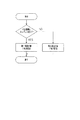
といった態様で、クランクパルスに対する気筒の割り当てができるようになる。そしてこれにより、上記制御装置5では、図10にその手順を示すように、
( 1)上記判定期間の認識に基づき、同判定期間内に吸気カムパルスが存在するか否かを判断する。
( 2)この判断の結果、吸気カムパルスが存在していれば、当該判定期間の終了後所定パルス(3パルス)をカウントして、第1気筒圧縮上死点を検出する。
( 3)同判断の結果、吸気カムパルスが存在していなければ、当該判定期間の終了後所定パルス(3パルス)をカウントして、第6気筒圧縮上死点を検出する。
といった態様で、気筒判別を行うことができるようになる。
【0012】
なお、他の気筒については、点火気筒順序に基づき、上記検出される第1気筒及び第6気筒間のクランクパルスによる補間を行うことによって、その判別を行うことができる。
【0013】
また、上記判定期間は通常、上記伝達機構2を形成する各部品の製造角度公差やベルト伸縮誤差、更には信号の通信遅れ等を加味した角度誤差B゜CA(吸気カム軸3が遅れる側)とC゜CA(吸気カム軸3が進む側)との和からなる角度範囲(B+C)゜CAとして設定される。
【0014】
ところで、クランク軸1とカム軸3及び4とが通常、上記伝達機構2を通じて2対1の回転角度に維持されるように回転することは上述した。ただし、これらクランク軸1、伝達機構2、そしてカム軸3及び4を通じて上記吸気バルブ32や排気バルブ42の開閉タイミングをエンジンの例えば定格出力時において最適のタイミングとなるよう固定的に設定してしまうと、同エンジンの低負荷運転時にはそのタイミングが微妙にずれ、排気の吹き返しが生じるなどの不都合を招くようになる。
【0015】
そこで従来は、吸気カム軸3と吸気カムプーリ23との間、或いは排気カム軸4と排気カムプーリ24との間に介在されて、それら相互の回転位相、ひいてはクランク軸1とカム軸3或いは4との間の回転位相を調整する回転位相調整機構を設け、該回転位相調整機構を通じて、上記吸気バルブ32や排気バルブ42の開閉タイミングを可変制御するなどの方法が講じられている。
【0016】
すなわち、こうしたバルブタイミング制御装置では、例えば先の図8の構成を流用すれば、吸気カム軸3と吸気カムプーリ23との間に上記回転位相調整機構を設けるとともに、上述したクランクパルスの任意のパルスと吸気カムパルスとの位相差を監視し、該位相差がエンジンのその都度の運転状態に適した所定の値となるよう、同設けた回転位相調整機構による調整量を制御する構成となる。
【0017】
【発明が解決しようとする課題】
このように、バルブタイミング制御装置自体は、図8に示される気筒判別装置を流用して構成することができる。しかし、同図8に示される構成に基づいて、これらバルブタイミング制御装置としての機能と気筒判別装置としての機能とを同時に満たそうとすると、次のような不都合が新たに生じることとなる。
【0018】
すなわち、バルブタイミング制御装置にあっては、上述した回転位相調整機構を通じて積極的にクランク軸1と吸気カム軸3との間の回転位相を調整することとなるが、こうした回転位相の調整動作が先の気筒判別動作と同時に実行されるとなると、クランクパルスの前記判定期間内に出力されるべき吸気カムパルスが同判定期間を外れて出力されるといった事態も当然起こり得る。もしもこのように、判定期間内に出力されるべき吸気カムパルスが判定期間を外れて出力されるようなことが起こった場合には、本来は第1気筒の圧縮上死点として判定されるべきところが第6気筒の圧縮上死点として誤判定されることとなる。こうした誤判定は、気筒の判別はもとより、以降の点火時期、並びに燃料噴射タイミングの管理や制御を全て狂わせ、非常に危険な状態を呈するようになる。
【0019】
なお、こうした不都合を回避するためには、上記回転位相調整機構の装着されていない排気カム軸4側にも前記カム角センサ3Sに相当するカム角センサを新たに設け、気筒判別動作には、この新たに設けた排気カム軸4側のカム角センサを専ら用いる構成とすることもできる。
【0020】
しかし、こうした構成では、上記カム角センサが余分に必要になるとともに、DOHC(ダブル・オーバー・ヘッド・カム・シャフト)タイプのエンジンへの適用に限定されることとなり、経済性並びに汎用性の面で尚、問題が残る。
【0021】
この発明は、こうした実情に鑑みてなされたものであり、より簡単且つ汎用性に優れた構成にて、多気筒内燃機関(エンジン)の気筒判別、並びに同内燃機関の吸気バルブや排気バルブの適正な開閉タイミング制御を精度よく実現することのできる気筒判別機能を有するバルブタイミング制御装置を提供することを目的とする。
【0022】
【課題を解決するための手段】
こうした目的を達成するため、この発明では、内燃機関のクランク軸と同内燃機関の吸気バルブ若しくは排気バルブの開閉を行うカムのカム軸とが2対1の回転角度に維持されるよう前記クランク軸の回転をカム軸に伝達する伝達手段と、該伝達手段に介在されて前記クランク軸と前記カム軸との間の回転位相を調整する回転位相調整手段と、前記クランク軸に配設されてその回転角度を検出するクランク角センサと、前記カム軸に対し少なくとも1つは同カム軸の180度反対側の位置に他の1つを有さないかたちで配設された1乃至複数の信号誘起手段と共働して前記カム軸が所定の回転角度となる毎にその旨示すカム信号を出力するカム角センサと、前記クランク軸の任意の角度を基準とした回転角度検出信号と前記カム信号との位相差を監視して、該位相差が所定の目標値となるよう前記回転位相調整手段による調整量を決定する位相制御手段と、前記クランク角センサによる回転角度検出信号に対し少なくとも前記回転位相調整手段による位相調整範囲に対応する角度範囲より大きく且つ360度クランク角より小さい判定角度範囲を設定し、該設定した判定角度範囲内の前記カム信号出力の有無に基づいて前記内燃機関の気筒を判別する気筒判別手段とを具える構成とする。
【0023】
【作用】
こうした構成によれば、クランク軸に対するカム軸の回転位相は上記回転位相調整手段を通じて任意に可変設定されるようになる。また、その設定される回転位相の関係は、上記位相制御手段を通じて、目標とする所定の関係すなわち当該内燃機関のその都度の運転状態に見合った最適なバルブ開閉タイミングが得られるよう、クランク軸の任意の角度を基準とした回転角度検出信号と上記カム信号との位相差の監視に基づき、いわば動的にフィードバック制御される。こうしたフィードバック制御によって、上記バルブの開閉タイミングは、内燃機関の運転状態に追従して常に好適なタイミングに制御されるようになる。
【0024】
一方、上記気筒判別手段は、気筒判別のための上記判定角度範囲を、これを例えばX度クランク角として、
回転位相調整手段による位相調整範囲に対応したクランク角
< X < 360度クランク角
といった範囲に設定する。このため、上記バルブタイミングの制御にあって、同回転位相調整手段を通じたクランク軸とカム軸との積極的な位相調整が行われ、またその位相調整量が最大量に達する場合であっても、一旦この判定角度範囲に同期して出力されるよう設定されたカム信号が同判定角度範囲を外れて出力されるようなことはなくなる。したがって、1つのカム軸を対象とした只1つのカム角センサを通じて、こうした気筒判別動作と上記バルブタイミングの制御動作とが同時に実行されても、誤った気筒判別が行われることはない。
【0025】
しかも、上記伝達手段についてはこれを、クランク軸とカム軸との回転角度を2対1の関係に維持するものとし、また上記カム角センサについてはこれを、
(a)前記カム軸に対し少なくとも1つは同カム軸の180度反対側の位置に他の1つを有さないかたちで配設された1乃至複数の信号誘起手段と共働して前記カム軸が所定の回転角度となる毎にその旨示すカム信号を出力する構成。
すなわち、上記信号誘起手段がカム軸に対して複数個配設される場合にあっては、
(a’)上記判定角度範囲に同期したカム信号を誘起する任意の1つの信号誘起手段の他の信号誘起手段についてはこれが、該任意の1つの信号誘起手段から180度の間隔以外の間隔をもって配設された構成。
といった構成を有するものとしたことで、気筒判別のためのアルゴリズムについてもこれを、前述した簡素なものに保つことが可能になる。具体的には、上記他の信号誘起手段が上記任意の1つの信号誘起手段から180度の間隔をもって配設される場合には、これら他の信号誘起手段と任意の1つの信号誘起手段とが互いに真裏に対向して配置されるようになる。したがってこの場合、それら信号誘起手段によって誘起されるカム信号の何れもが上記判定角度範囲に同期して出力されることとなり、例えば前述した6気筒の内燃機関にあっては、その第1気筒と第6気筒とが単純には判別できなくなる。もっとも、これを監視する側で、例えばその一方にのみ対応して、上記クランク角センサによる回転角度検出信号のカウントに基づくフラグ制御を行うなど、複雑な気筒判別アルゴリズムを採用するようにすれば、必ずしもその判別は不可能ではない。しかし、上記(a)の条件が満たされるかたちで信号誘起手段の配設を行うようにすれば、このような複雑な気筒判別アルゴリズムを用いずとも、それら気筒についての正確な判別を行うことが可能となる。なお、カム軸に設けられる上記信号誘起手段については、これをより多く設けることが、バルブタイミングの制御において上記フィードバック制御のサンプル周期を縮め、ひいてはより緻密な位相制御を行う上で有効となる。
【0026】
因みに、上記複数の信号誘起手段をカム軸の周囲に等間隔に配設する場合、それら信号誘起手段の数を奇数とすれば、上記( a)の条件は満たされる。
また、複数の信号誘起手段をこのように等間隔に配設する場合には、上記気筒判別手段としても、上記判定角度範囲の最大値を(360度クランク角/信号誘起手段数)以内に設定することが、上記カム信号の重複検出を避ける上で有効となる。
【0027】
また、上記伝達手段がクランク軸とカム軸との回転角度を2対1の関係に維持するものであり、またこの信号誘起手段がカム軸に対して複数個配設される場合にあって、
( b)上記判定角度範囲に同期したカム信号を誘起する任意の1つの信号誘起手段の他の信号誘起手段についてはこれを、該任意の1つの信号誘起手段から180度の間隔以外で且つ、(360度/気筒数)の倍数の間隔をもって配設する。
ようにすれば、上記に加え、気筒の数に対応して生じるカム軸の回転速度変動に同期して、常に同一の条件のもとで上記カム信号が出力されるようになる。このため、クランク軸の任意の角度を基準とした回転角度検出信号とこのカム信号との位相差にばらつきが生じるようなこともなくなり、更に正確なバルブタイミング制御が可能になる。そしてこの場合も、複数の信号誘起手段を等間隔に配設する際には、上記気筒判別手段において、上記判定角度範囲の最大値を(360度クランク角/信号誘起手段数)以内に設定することが、同カム信号の重複検出を避ける上で有効となる。
【0028】
また更に、
( c)前記クランク角センサによる回転角度検出信号を前記クランク軸の任意の角度を基準として前記信号誘起手段の数に分周する分周手段。
を併せ具え、
( d)前記位相制御手段は、この分周された回転角度検出信号と上記カム信号との位相差を監視して上記回転位相調整手段による調整量の決定を行う。
構成とすれば、上記位相差の監視もより容易且つ確実なものとなる。
【0029】
【実施例】
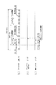
図1に、この発明にかかる気筒判別機能を有するバルブタイミング制御装置の第1の実施例を示す。
【0030】
はじめに、同図1を参照して、この第1の実施例の装置の構成を説明する。
この図1において、図8に示した要素と同一若しくは対応する要素については便宜上、同一若しくは対応する符号を付して示している。
【0031】
すなわち図1(a)に示されるように、この実施例の装置にあっても、エンジンクランク軸1の回転は、伝達機構2によって吸気カム軸3及び排気カム軸4に伝達される。この伝達機構2が、クランクプーリ21、タイミングベルト22、吸気カムプーリ23、及び排気カムプーリ24等によって形成されること、またこれらベルトやプーリを通じて、クランク軸1とカム軸3及び4とが2対1の回転角度に維持されるようその伝達係数が設定されることは前述した通りである。そして、吸気カム軸3に設けられているカム31及び排気カム軸4に設けられているカム41は、それぞれこうしてクランク軸1と2対1の回転角度に維持されるそれらカム軸3及び4の回動に基づいて吸気バルブ32及び排気バルブ42を開閉駆動する。
【0032】
また、上記吸気カムプーリ23には、外部から与えられる駆動信号(回転位相調整信号)に基づき該カムプーリ23と吸気カム軸3とを相対回動せしめてクランク軸1とカム軸3との間の回転位相を調整する回転位相調整機構6が組み込まれている。ただし、該回転位相調整機構6としてのこのような構成は既に周知であり、同機構6についてのここでの改めての説明は割愛する。
【0033】
また、この実施例の装置では、クランク軸1と吸気カム軸3との相対回転角度を基準として、上記各バルブの開閉タイミング制御、並びに気筒判別を実行するようになっている。
【0034】
すなわち、上記クランク軸1には、図1(b)にその態様を拡大して示すような複数のパルス誘起体11が設けられるとともに、それら誘起体11の個々が同図1(a)に示される如く対向する位置に達する毎に1つのパルスを発生するパルス発生器12がクランク軸1の近傍に固設されている。このパルス発生器12が通常、磁気センサ、ホールセンサ、或いは光センサ等によって構成され、上記パルス誘起体11としては、それら使用されるセンサに対しパルスを誘起し得る材質若しくは形状の部材が用いられることは前述した。また、この実施例の装置にあっても、パルス誘起体11は、同図1(b)に示されるように、1箇所のみその配設間隔が30゜CA(クランク角)となり、他の全てが10゜CA間隔となる34個(等間隔の36個から2個分を削除した数)の誘起体によって構成されている。以下でも便宜上、これらパルス誘起体11及びパルス発生器12を合わせてクランク角センサ1Sといい、その出力されるパルスをクランクパルスという。
【0035】
一方、上記吸気カム軸3には、図1(c)に示されるように、120°の間隔(=240°CA間隔)をもって3個のパルス誘起体33a、33b、及び33cが設けられるとともに、これら誘起体33a、33b、及び33cが図1(a)に示される如く対向する位置に達する毎に1つのパルスを発生するパルス発生器34が同吸気カム軸3の近傍に固設されている。このパルス発生器34も通常、磁気センサ、ホールセンサ、或いは光センサ等によって構成され、パルス誘起体33(33a、33b、及び33c)としても、それら使用されるセンサに対しパルスを誘起し得る材質若しくは形状の部材が用いられる。そして以下でも便宜上、これらパルス誘起体33及びパルス発生器34を合わせてカム角センサ3Sといい、その出力されるパルスを吸気カムパルスという。
【0036】
これら出力されるクランクパルス及び吸気カムパルスは、コンピュータ等からなる電子制御装置50に取り込まれ、そこで上記吸気バルブ32及び排気バルブ42の開閉タイミング制御、並びに当該多気筒エンジンの気筒判別、更にはそれら気筒別の点火時期や燃料噴射タイミングの管理・制御等に供される。
【0037】
この実施例の装置において、電子制御装置50は基本的に、気筒判別部51、分周部52、及びバルブタイミング制御部53を具えて構成される。
気筒判別部51は、上記クランクパルスと吸気カムパルスとの関係から当該多気筒エンジンの気筒判別を行う部分であり、その気筒判別結果が、電子制御装置50内の図示しない点火時期制御部及び燃料噴射制御部に対してそれぞれ与えられるようになる。
【0038】
また、分周部52は、上記クランクパルスを入力して、これを吸気カムパルスに対応させるべく上記カム角センサ3Sを構成するパルス誘起体の数、すなわちここでは「3」に分周する部分である。この分周に際しては例えば、クランク軸1の基準とすべき任意の角度に対応したクランクパルスを認識し、この認識したクランクパルスから同パルスをカウントしてこれが240°CAに相当する数に達する毎に、その分周パルスとして1つのパルスを出力する、などの手法が採られるものとする。
【0039】
そして、バルブタイミング制御部53は、上記吸気カムパルスとこのクランクパルスの分周パルスとを入力して、それらパルスの位相差が目標値θとなるように、位相調整機構駆動部54を通じて上記位相調整機構6に回転位相調整信号を出力する部分である。なお、上記目標値θは、エンジン運転状態検出部55から出力される当該エンジンの運転状態に基づき、同バルブタイミング制御装置53内で演算され、決定される。この決定方法としては、例えば
( A)エンジンの回転数と負荷の大きさとに応じた同目標値θとしての最適値を予めの実験等により求めてこれをメモリに記憶しておき、エンジン実働時のこれら回転数と負荷の大きさに関する情報を上記エンジン運転状態検出部55を通じて得て、それに見合った目標値θを同メモリから読み出す方法。
( B)エンジンの運転状態を示す情報としてエンジンの筒内圧に関する情報を上記エンジン運転状態検出部55を通じて得る。そして、同エンジンのシリンダ内での燃焼がそれら運転状態毎に最大効率で行われるような吸気バルブ32、或いは排気バルブ42の開閉タイミングを適宜の演算プログラムによって学習し、この学習値に基づいてそれらバルブの最適開閉タイミングに対応する目標値θを逐次決定する方法。
などがある。
【0040】
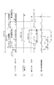
図2は、当該多気筒エンジンがここでも直列6気筒エンジンであることを想定して、上記クランクパルス及び吸気カムパルスに基づくこの実施例の装置による気筒判別態様、並びにバルブタイミング制御態様を示したものである。以下、同図2を併せ参照して、該実施例の装置の動作を更に詳述する。
【0041】
はじめに、この実施例の装置の気筒判別にかかる動作について説明する。
上述のように、この実施例の装置では、クランク軸1に対し、1箇所のみその配設間隔が30゜CAとなり、他の全てが10゜CA間隔となる34個のパルス誘起体11を設けていることから、上記クランク角センサ1Sからは、クランク軸1の回転に対応して図2(a)に示される態様でクランクパルスが出力されるようになる。
【0042】
電子制御装置50の気筒判別部51では、このようなクランクパルスのパルス周期を計測することにより、30°CAの間隔となる次の1パルスを特定し、そのパルスを起点として一定間隔の判定期間(判定角度範囲)を設定する。上記回転位相調整機構6による回転位相の最大調整量がA°CAであり、また上記伝達機構2を形成する各部品の製造角度公差やベルト伸縮誤差、更には信号の通信遅れ等を加味した角度誤差がB゜CA(吸気カム軸3が遅れる側)及びC゜CA(吸気カム軸3が進む側)であるとすると、この気筒判別部51では、少なくともこれら角度の合計値
(A+B+C)゜CA
を、該判定期間として設定する。
【0043】
一方、上記吸気カムパルスは、こうしたクランクパルスに対し、同図2(c)に示されるタイミングにて発生されるものとする。すなわち、クランク軸1の2回転につき1回転する吸気カム軸3にあって上記吸気カムパルスを出力するカム角センサ3Sからは、同吸気カム軸3の1回転につき2回生じる上記判定期間のうちの一方に同期して吸気カムパルスのうちの1つが出力されるよう、クランク角センサ1Sに対する該カム角センサ3Sの配設角度が予め設定されているものとする。
【0044】
このため、当該直列6気筒エンジンの点火気筒順序が、先の例の場合と同様、「第1気筒→第5気筒→第3気筒→第6気筒→第2気筒→第4気筒」の順であるとすると、ここでも例えば
( a)上記吸気カムパルスに同期して判定期間が認識される場合には、同判定期間の終了パルスから所定パルス後(図2の例では3パルス後)を第1気筒の上死点(圧縮上死点)とする。
( b)上記吸気カムパルスが生じない判定期間が認識される場合には、同判定期間の終了パルスから所定パルス後(図2の例では3パルス後、すなわち第1気筒の上死点から360゜CA後)を第6気筒の上死点(圧縮上死点)とする。
といった態様で、クランクパルスに対する気筒の割り当てができるようになる。そしてこれにより、上記気筒判別部51では、先の図10にその手順を示した通り、
( 1)上記判定期間の認識に基づき、同判定期間内に吸気カムパルスが存在するか否かを判断する。
( 2)この判断の結果、吸気カムパルスが存在していれば、当該判定期間の終了後所定パルス(3パルス)をカウントして、第1気筒圧縮上死点を検出する。
( 3)同判断の結果、吸気カムパルスが存在していなければ、当該判定期間の終了後所定パルス(3パルス)をカウントして、第6気筒圧縮上死点を検出する。
といった態様で、気筒判別を行うことができるようになる。他の気筒については、点火気筒順序に基づき、上記検出される第1気筒及び第6気筒間のクランクパルスによる補間を行うことによってその判別を行うことができることは前述した通りである。
【0045】
このように、この実施例の装置によれば、上記判定期間を、回転位相調整機構6による回転位相の最大調整量A°CA、並びに伝達機構2を形成する各部品の角度誤差B゜CA及びC゜CAを少なくとも含む角度範囲として設定している。このため、たとえ次に説明するバルブタイミング制御において、クランク軸1と吸気カム軸3との回転位相が調整されたとしても、図2(c)に示される如く、一旦この判定期間に入るようその出力角度が調整された吸気カムパルスが同判定期間から外れて出力されることはなくなる。したがって、バルブタイミング制御と併用される場合であっても、こうした気筒判別にかかる精度は常に正確に維持されるようになる。
【0046】
なお、この実施例の場合、上記判定期間としての最大角度範囲は120゜CA以内であればよい。この120゜CA以内であれば、上記吸気カムパルスを重複して検出してしまうこともない。因みに、この吸気カムパルスを発生するためのパルス誘起体がカム軸3に対して奇数個、等間隔に配設される場合には、一般的に
(A+B+C)゜CA ≦ 判定期間 ≦ 360゜CA/誘起体の数
といった範囲で、同判定期間を定めることができる。
【0047】
次に、この実施例の装置のバルブタイミング制御にかかる動作について説明する。
電子制御装置50の分周部52は、クランク軸1の回転に対応して図2(a)に示される態様で出力されるクランクパルスに対し、上述した分周手法に基づき、例えば同図2(b)に示される態様にて、分周パルスを生成し、出力するものとする。因みにこの例では、その基準とするクランクパルスを、吸気カムパルスと同期している判定期間の最後のクランクパルスに特定し、該特定したクランクパルスから240°CAに相当する数に達する毎に、その分周パルスとして1つのパルスを出力する設定となっている。換言すれば、上記吸気カムパルスは、同図2(b)及び(c)に示されるように、このクランクパルス分周パルスに対し、B゜CAから(A+B)゜CAだけ進む側に発生する設定となっている。
【0048】
一方、上記バルブタイミング制御部53は、これら吸気カムパルス及びクランクパルス分周パルスに基づき、例えば図3に示される手順をもって、クランク軸1と吸気カム軸3との間の相対回転位相をフィードバック制御する。
【0049】
すなわち、バルブタイミング制御部53では、同図3に示されるように、上記吸気カムパルスの発生を確認し(ステップ100)且つ、上記分周パルスの発生を確認した後(ステップ110)、これら吸気カムパルスと分周パルスとのその時点での位相差(A+B)゜CAを計測する(ステップ120)。
【0050】
こうして吸気カムパルスと分周パルスとの位相差を計測した同制御部53は次いで、上記エンジン運転状態検出部55を通じて当該エンジンのその時点での運転状態を取り込み(ステップ130)、上記計測した位相差についての目標値θを演算する(ステップ140)。こうした目標値θについての演算、並びに決定手法については上述した(上記( A)或いは( B)の方法)。
【0051】
これら位相差についての計測値(A+B)゜CA及びその目標値θを得た制御部53は更に、これらの値を比較して(ステップ150及び160)、
θ = A+B …(1)
であれば、クランク軸1と吸気カム軸3との間の相対回転位相が目標とする位相にある旨判断して、次の吸気パルス及び分周パルスの発生を待つ。また、同比較の結果、
θ > A+B …(2)
であれば、吸気カム31が遅れている旨判断する。そしてこの場合は、上記位相調整機構駆動部54及び回転位相調整機構6を通じて、該吸気カム31を進角させる側に、クランク軸1と吸気カム軸3との間の相対回転位相を調整して(ステップ171)、次の吸気パルス及び分周パルスの発生を待つ。他方、同比較の結果、これら(1)式及び(2)式の何れの条件も満たされないときには、吸気カム31が進んでいる旨判断する。そしてこの場合には、上記位相調整機構駆動部54及び回転位相調整機構6を通じて、同吸気カム31を遅角させる側に、クランク軸1と吸気カム軸3との間の相対回転位相を調整して(ステップ172)、次の吸気パルス及び分周パルスの発生を待つ。
【0052】
バルブタイミング制御部53を通じて、このようなフィードバック制御が繰り返されることにより、少なくとも吸気バルブ32の開閉タイミングは、その都度のエンジン運転状態に応じた好適なタイミングに制御されるようになる。
【0053】
このように、この実施例の装置によれば、上記吸気カムパルスとクランクパルスの分周パルスとに基づいて、バルブの開閉タイミングを好適に制御することができるようになる。
【0054】
また、特にこの実施例の装置では、吸気カム軸3に対し120゜間隔で3個のパルス誘起体33a、33b、及び33cを設け、クランク軸1の240゜CA毎にこれら誘起体に対応した吸気カムパルスが出力される構成としている。このため、図3に例示した手順にてバルブタイミング制御を行う場合であれ、十分に密度の高いサンプリング周期をもってこれら吸気カムパルス、並びに分周パルスが取り込まれるようになり、こうしたバルブの開閉タイミング制御も高い精度に維持されるようになる。
【0055】
また、上記の例のように、対象となるエンジンが直列6気筒エンジンである場合、図1(a)に示される吸気バルブ32や排気バルブ42は、カム軸3或いは4の軸方向(図面と垂直の方向)に6箇所ずつ配設されるとともに、これらバルブを開閉するための吸気カム31や排気カム41も、同カム軸3或いは4の軸方向に6箇所ずつ配設される。そして吸気カム軸3についていえば、それら6個の吸気カム31は互いに60゜(120゜CA)の間隔をもって該吸気カム軸3に配設されることとなる。このため、同吸気カム軸3には通常、それら吸気カムによるバルブ開閉動作に起因して、極端には図2(d)に示されるような回転速度変動が生じるようになる。しかしこの実施例の装置のように、吸気カム軸3に対して120゜間隔で3個のパルス誘起体を設け、その120゜(240゜CA)毎にこれら誘起体に対応した吸気カムパルスが出力される構成によれば、図2(d)に併せ示されるように、その回転速度変動に同期して、常に同様の回転速度状態において吸気カムパルスが出力されるようになり、こうしたカム軸の回転速度変動が上記バルブタイミング制御に及ぼす影響は良好に回避される。
【0056】
そして上述したように、同実施例の装置によれば、こうしたバルブタイミング制御動作と気筒判別動作とが並行して同時実行される場合であっても、気筒判別にかかる精度は常に正確に維持される。
【0057】
ところで、上記第1の実施例の装置にあっては、バルブタイミング制御に際しての吸気カムパルスのサンプリング周期を縮め、ひいてはフィードバック制御の収束性を高めるべく、吸気カム軸3に3個のパルス誘起体を設けたが、この発明にかかるバルブタイミング制御装置によれば、同吸気カム軸3に配されるパルス誘起体は基本的に1個あればよい。
【0058】
図4に、この発明にかかる気筒判別機能を有するバルブタイミング制御装置の第2の実施例として、こうした吸気カム軸3に配されるパルス誘起体を1個のみとした装置を示す。なお、この図4においても、図1に示した要素と同一若しくは対応する要素については同一若しくは対応する符号を付して示しており、それら要素についての重複する説明は割愛する。
【0059】
同図4に示されるように、この第2の実施例の装置では、カム角センサ3Sを構成するパルス誘起体として同誘起体33を1個のみ具え、これから図5(c)に示されるような吸気カム軸3の1回転(720゜CA)につき1個の吸気カムパルスが出力されるようにしている。
【0060】
この第2の実施例の装置にあっても、そのバルブタイミング制御は、先の図3に示される手順をもって実行されるが、上記第1の実施例の装置に比して、吸気カムパルスのサンプリング周期が3倍に延びるため、そのフィードバック制御での収束性は確かに悪化する。
【0061】
しかし、図5(a)及び(c)に示されるように、気筒判別部51は、ここでも上記判定期間を、回転位相調整機構6による回転位相の最大調整量A°CA、並びに伝達機構2を形成する各部品の角度誤差B゜CA及びC゜CAを少なくとも含む角度範囲、すなわち
判定期間 ≧ (A+B+C)゜CA
として設定し、この設定した判定期間に同期した上記吸気カムパルスの有無に基づいて気筒判別を実行する。
【0062】
このため、この第2の実施例の装置にあっても、バルブタイミング制御と併用され、クランク軸1と吸気カム軸3との回転位相が積極的に調整されることがあったとしても、該気筒判別にかかる精度は常に正確に維持されるようになる。
【0063】
なお、この第2の実施例の装置の場合、上記判定期間としての最大角度範囲は330゜CA以内であればよい。この330゜CA以内であれば、上記吸気カムパルスを重複して検出してしまうような不都合は回避される。
【0064】
また、この発明にかかる気筒判別機能を有するバルブタイミング制御装置において、上記吸気カムパルスは、必ずしも等間隔のパルスとして出力される必要はない。吸気カム軸3の1回転(720゜CA)につき複数個出力されるとする吸気カムパルスが不等間隔であったとしても、上記と同等の作用効果を得ることはできる。
図6に、この発明にかかる気筒判別機能を有するバルブタイミング制御装置の第3の実施例として、複数のパルス誘起体が吸気カム軸3に対して不等間隔に配される装置を示す。なお、この図6においても、図1或いは図4に示した要素と同一若しくは対応する要素については同一若しくは対応する符号を付して示しており、それら要素についての重複する説明は割愛する。
【0065】
同図6(c)に拡大して示すように、この第3の実施例の装置は、カム角センサ3Sを構成するパルス誘起体として、それぞれ90゜→180゜→90゜といった間隔で配設される3個のパルス誘起体33d、33e、及び33fを具えた構成となっている。このため、カム角センサ3Sから出力される吸気カムパルスも、図7(c)に示されるような不等間隔のパルスとなる。
【0066】
また、電子制御装置50の分周部52からは、この不等間隔の吸気カムパルスに対応して、同図7(b)に示されるような分周パルスが生成出力されるものとする。
【0067】
そして、この第3の実施例の装置にあっても、そのバルブタイミング制御は、先の図3に示される手順をもって実行される。吸気カムパルスが不等間隔であるとはいえ、そのサンプリング数(密度)は先の第1の実施例の装置の場合と同様であり、前述したフィードバック制御での収束性は、この第3の実施例の装置によっても良好に維持される。
【0068】
また、図7(a)及び(c)に示されるように、気筒判別部51は、ここでも上記判定期間を、回転位相調整機構6による回転位相の最大調整量A°CA、並びに伝達機構2を形成する各部品の角度誤差B゜CA及びC゜CAを少なくとも含む角度範囲(A+B+C)゜CAとして設定し、この設定した判定期間に同期した上記吸気カムパルスの有無に基づいて気筒判別を実行する。
【0069】
なおここで、この判定期間に同期して出力される吸気カムパルスとしては、上記3個のパルス誘起体のうち、パルス誘起体33dに対応して出力されるパルスが選ばれる。これは、伝達機構2を通じてクランク軸1と吸気カム軸3との回転角度が2対1の関係に設定される場合に、気筒判別のためのアルゴリズムを図10に示したような簡単なものに維持する上で有効となる。
【0070】
すなわち、該判定期間に同期して出力される吸気カムパルスに対応したパルス誘起体の裏側(180゜離れた位置)にもパルス誘起体が存在する場合には、それらパルス誘起体によって誘起されるパルスの何れもが、クランク軸1の1周目と2周目とで、この判定期間に同期して出力されるようになる。その場合、例えば前述した6気筒のエンジンにあっては、その第1気筒と第6気筒とが単純には判別できなくなる。勿論、これを監視する気筒判別部51側で、例えばその一方にのみ対応してクランクパルスのカウントに基づくフラグ制御を行うなど、複雑な気筒判別アルゴリズムを採用するようにすれば、必ずしもその判別は不可能ではない。しかし、その裏側にパルス誘起体の存在しない上記パルス誘起体3dに対応した吸気カムパルスが上記判定期間に同期して出力されるようにすれば、このような複雑な気筒判別アルゴリズムを用いずとも、それら気筒についての正確な判別を行うことが可能となる。
【0071】
そして、この第3の実施例の装置にあっても、バルブタイミング制御と併用され、クランク軸1と吸気カム軸3との回転位相が積極的に調整されることがあったとしても、該気筒判別にかかる精度は常に正確に維持される。
【0072】
また、特にこの第3の実施例の装置のように、複数のパルス誘起体が90゜の倍数の間隔をもって配設されるものは、例えば直列4気筒や直列8気筒といったエンジンに適用されることが、そのバルブタイミング制御をより正確に行う上で望ましい。
【0073】
例えば4気筒エンジンの場合、吸気バルブ31や吸気カム32が吸気カム軸3の軸方向(図面と垂直の方向)に4箇所ずつ配設される。そしてそれら4箇所の吸気カム32は、互いに90゜(180゜CA)の間隔をもって吸気カム軸3に配設されることとなる。このため、同吸気カム軸3には通常、それら吸気カムによるバルブ開閉動作に起因して、極端には図7(d)に示されるような回転速度変動が生じるようになる。しかしこの第3の実施例の装置のように、吸気カム軸3に対して90゜の倍数となる間隔で3個のパルス誘起体を設け、その90゜(180゜CA)若しくは180゜(360゜CA)毎にこれら誘起体に対応した吸気カムパルスが出力される構成によれば、図7(d)に併せ示されるように、その回転速度変動に同期して、常に同様の回転速度状態において吸気カムパルスが出力されるようになる。そしてこの場合も、こうしたカム軸の回転速度変動が上記バルブタイミング制御に及ぼす影響は良好に回避されるようになる。
【0074】
なお、この4気筒であるとするエンジンの点火気筒順序が、「第1気筒→第4気筒→第3気筒→第2気筒」の順であるとすると、例えば図7(a)に示されるように、
( a)吸気カムパルスに同期して判定期間が認識される場合には、同判定期間の終了パルスを第1気筒の上死点(圧縮上死点)とする。
( b)吸気カムパルスが生じない判定期間が認識される場合には、同判定期間の終了パルスを第3気筒の上死点(圧縮上死点)とする。
といった態様で、クランクパルスに対する気筒の割り当てが可能となる。
【0075】
ところで、上記第1乃至第3の実施例においては何れも、カム角センサ3Sを構成するパルス誘起体が3個或いは1個である場合について例示したが、これらパルス誘起体については、これをより多く設けることが、バルブタイミングの制御において上記フィードバック制御のサンプル周期を縮め、ひいてはより緻密な位相制御を行う上で有効となる。
【0076】
また一般的には、伝達機構がクランク軸とカム軸との回転角度を2対1の関係に維持するものであり、また上記パルス誘起体がカム軸に対して複数個配設される場合には、
・判定期間に同期したカムパルスを誘起する任意の1つのパルス誘起体の他の誘起体についてはこれを、該任意の1つのパルス誘起体から180度の間隔以外の間隔をもって配設する。
ことが、気筒判別のためのアルゴリズムを図10に示したような簡素なものに保つ上で有効である。上記複数のパルス誘起体をカム軸の周囲に等間隔に配設する場合には、それらパルス誘起体の数を奇数とすることでこうした条件は満たされる。
【0077】
また、上記カム角センサを構成するパルス誘起体の数は偶数であってもよい。その場合、同条件が満たされるためには、それらパルス誘起体が等間隔に配されることはないが、この発明にかかる気筒判別機能を有するバルブタイミング制御装置としての機能は十分に満たされる。
【0078】
そして一般的には、同条件に加えて更に、上記カム角センサを構成するパルス誘起体を、(360度/気筒数)の倍数の間隔をもって配設するようにすれば、カム軸の回転速度変動がバルブタイミング制御に及ぼす影響なども良好に回避されるようになる。
【0079】
また、上記各実施例の装置にあっては、クランクパルスを上記パルス誘起体の数に分周する分周部をその電子制御装置内に有しているが、必ずしもこのような分周部を具える必要はない。要は、クランク軸の任意の角度を基準としたクランクパルスとカムパルスとの位相差が監視できるものであればよく、他に例えば、基準とするクランクパルスから同パルスのカウントに基づきその位相を累積することでカムパルスが出力されるべきタイミングを推定し、その推定値と実際に出力されたカムパルスとの位相差を求める、等の方法によって同位相差を監視するようにしてもよい。
【0080】
また、この発明にかかる気筒判別機能を有するバルブタイミング制御装置によれば、上記第1乃至第3の実施例として例示されるように、吸気カム軸であれ、排気カム軸であれ、クランク軸と連動する1つのカム軸があればよく、その適用されるエンジンがDOHC(ダブル・オーバー・ヘッド・カム・シャフト)タイプのエンジンである必要はない。
【0081】
【発明の効果】
以上説明したように、この発明によれば、より簡単且つ汎用性に優れた構成にて、多気筒内燃機関(エンジン)の気筒判別、並びに同内燃機関の吸気バルブや排気バルブの適正な開閉タイミング制御を精度よく実現することができるようになる。
【図面の簡単な説明】
【図1】この発明にかかる気筒判別機能を有するバルブタイミング制御装置の第1の実施例についてその構成を示すブロック図である。
【図2】第1の実施例の装置の動作例を示すタイミングチャートである。
【図3】第1の実施例の装置によるバルブタイミング制御手順を示すフローチャートである。
【図4】この発明にかかる気筒判別機能を有するバルブタイミング制御装置の第2の実施例についてその構成を示すブロック図である。
【図5】第2の実施例の装置の動作例を示すタイミングチャートである。
【図6】この発明にかかる気筒判別機能を有するバルブタイミング制御装置の第3の実施例についてその構成を示すブロック図である。
【図7】第3の実施例の装置の動作例を示すタイミングチャートである。
【図8】多気筒エンジンの気筒判別装置についてその一般的な構成例を示すブロック図である。
【図9】図8に示される気筒判別装置の動作例を示すタイミングチャートである。
【図10】図8に示される気筒判別装置による気筒判別手順を示すフローチャートである。
【符号の説明】
1…クランク軸、1S…クランク角センサ、2…伝達機構、3…吸気カム軸、3S…カム角センサ、4…排気カム軸、5…制御装置、6…回転位相調整機構、11…クランク角センサを構成するパルス誘起体、12…クランク角センサを構成するパルス発生器、21…クランクプーリ、22…タイミングベルト、23…吸気カムプーリ、24…排気カムプーリ、31…カム、32…吸気バルブ、33(33a〜33f)…カム角センサを構成するパルス誘起体、34…カム角センサを構成するパルス発生器、41…カム、42…排気バルブ、50…電子制御装置、51…気筒判別部、52…分周部、53…バルブタイミング制御部、54…位相調整機構駆動部、55…エンジン運転状態検出部。[0001]
[Industrial application fields]
The present invention has a cylinder discrimination function in a multi-cylinder internal combustion engine, which has a function of discriminating between the cylinders and a function of appropriately controlling the opening / closing timing of intake valves and exhaust valves of the internal combustion engine. The present invention relates to a valve timing control device.
[0002]
[Prior art]
Conventionally, for example, a device as shown in FIG. 8 is known as a device for performing cylinder discrimination of a multi-cylinder engine (internal combustion engine).
[0003]
First, the outline of the cylinder discrimination device shown in FIG. 8 will be described.
As shown in FIG. 8, in such a cylinder discriminating apparatus, the rotation of the
[0004]
Here, the
[0005]
Further, in the cylinder discriminating apparatus shown in FIG. 8, the cylinder discrimination is performed based on the rotation angle of the
That is, the
[0006]
On the other hand, the
[0007]
These output crank pulses and intake cam pulses are taken into the control device 5, where they are used for cylinder discrimination of the multi-cylinder engine, and for management and control of ignition timing and fuel injection timing for each cylinder.
[0008]
FIG. 9 shows a cylinder discrimination mode based on the crank pulse and the intake cam pulse on the assumption that the multi-cylinder engine is an in-line 6-cylinder engine. Hereinafter, referring to FIG. 9 together, The operation of the cylinder discrimination device will be further described.
[0009]
In this cylinder discriminating apparatus, as shown in FIG. 9A, by measuring the pulse period of the crank pulse, the next one pulse having an interval of 30 ° CA is specified, and the pulse is set as a starting point. An interval determination period (determination angle range) is set. Such a determination period is set inside the control device 5. In this example, 60 ° CA corresponding to six crank pulses is defined as the determination period.
[0010]
On the other hand, the intake cam pulse is generated at the timing shown in FIG. 9B with respect to such a crank pulse. That is, from the
[0011]
For this reason, if the order of ignition cylinders of the in-line 6-cylinder engine is “first cylinder → 5th cylinder → 3rd cylinder → 6th cylinder → 2nd cylinder → 4th cylinder”, for example,
(a) When the determination period is recognized in synchronization with the intake cam pulse, the compression top dead center of the first cylinder is determined after a predetermined pulse (three pulses in the example of FIG. 9) after the end pulse of the determination period. To do.
(b) When a determination period in which the intake cam pulse does not occur is recognized, a predetermined pulse after the end pulse of the determination period (three pulses in the example of FIG. 9, ie, 360 ° from the top dead center of the first cylinder) The post-CA) is the compression top dead center of the sixth cylinder.
In this manner, the cylinder can be assigned to the crank pulse. And by this, in the said control apparatus 5, as the procedure is shown in FIG.
(1) Based on the recognition of the determination period, it is determined whether or not an intake cam pulse exists within the determination period.
(2) If the result of this determination is that there is an intake cam pulse, a predetermined pulse (3 pulses) is counted after the end of the determination period to detect the first cylinder compression top dead center.
(3) If the result of the determination is that there is no intake cam pulse, a predetermined pulse (3 pulses) is counted after the end of the determination period, and the sixth cylinder compression top dead center is detected.
In this manner, cylinder discrimination can be performed.
[0012]
For the other cylinders, the discrimination can be made by performing interpolation by the crank pulse between the detected first cylinder and the sixth cylinder based on the ignition cylinder order.
[0013]
In addition, the determination period usually includes an angle error B ° CA (a side on which the
[0014]
As described above, the
[0015]
Therefore, conventionally, it is interposed between the
[0016]
That is, in such a valve timing control device, for example, if the configuration shown in FIG. 8 is used, the rotational phase adjusting mechanism is provided between the
[0017]
[Problems to be solved by the invention]
In this way, the valve timing control device itself can be configured using the cylinder discrimination device shown in FIG. However, if the function as the valve timing control device and the function as the cylinder discrimination device are simultaneously satisfied based on the configuration shown in FIG. 8, the following inconveniences are newly generated.
[0018]
That is, in the valve timing control device, the rotational phase between the
[0019]
In order to avoid such inconvenience, a cam angle sensor corresponding to the
[0020]
However, such a configuration requires an extra cam angle sensor and is limited to application to a DOHC (double over head cam shaft) type engine, which is economical and versatile. Still, the problem remains.
[0021]
The present invention has been made in view of such circumstances, and with a simpler and more versatile configuration, the cylinder discrimination of a multi-cylinder internal combustion engine (engine) and the appropriateness of intake valves and exhaust valves of the internal combustion engine are made. An object of the present invention is to provide a valve timing control device having a cylinder discriminating function capable of realizing accurate opening / closing timing control.
[0022]
[Means for Solving the Problems]
In order to achieve these objects, the present inventionThe rotation of the crankshaft is transmitted to the camshaft so that the crankshaft of the internal combustion engine and the camshaft of the cam that opens and closes the intake valve or exhaust valve of the internal combustion engine are maintained at a 2-to-1 rotation angle.A transmission means, a rotation phase adjusting means for adjusting a rotation phase between the crankshaft and the camshaft, interposed in the transmission means, and a crank angle sensor disposed on the crankshaft for detecting the rotation angle When,At least one of the camshafts is disposed at a
[0023]
[Action]
According to such a configuration, the rotational phase of the camshaft with respect to the crankshaft is arbitrarily variably set through the rotational phase adjusting means. Further, the relationship between the set rotational phases is such that the crankshaft is controlled so that an optimal valve opening / closing timing corresponding to the target predetermined relationship, that is, the respective operating state of the internal combustion engine can be obtained through the phase control means. Based on monitoring of the phase difference between the rotation angle detection signal based on an arbitrary angle and the cam signal, so-called dynamic feedback control is performed. By such feedback control, the opening / closing timing of the valve is always controlled at a suitable timing following the operating state of the internal combustion engine.
[0024]
On the other hand, the cylinder discriminating means uses the judgment angle range for cylinder discrimination as an X-degree crank angle, for example.
Crank angle corresponding to the phase adjustment range by the rotation phase adjustment means
<X <360 degrees crank angle
Set to the range. For this reason, even in the case where the valve timing is controlled, positive phase adjustment between the crankshaft and the camshaft is performed through the rotation phase adjusting means, and the phase adjustment amount reaches the maximum amount. The cam signal set to be output once in synchronization with the determination angle range is not output outside the determination angle range. Therefore, even if such a cylinder determination operation and the valve timing control operation are simultaneously performed through one cam angle sensor for one camshaft, erroneous cylinder determination is not performed.
[0025]
In addition, the transmission means is to maintain the rotation angle between the crankshaft and the camshaft in a two-to-one relationship, and the cam angle sensor is
(A) At least one of the cam shafts cooperates with one or a plurality of signal inducing means arranged in a form that does not have another one at a
That is, when a plurality of the signal inducing means are arranged with respect to the camshaft,
(A ′) For any other signal inducing means for inducing any one of the signal inducing means for inducing a cam signal synchronized with the determination angle range, the signal inducing means has an interval other than 180 ° from the arbitrary one of the signal inducing means. Arranged configuration.
With this configuration, it is possible to keep the above-described simple algorithm for the cylinder discrimination algorithm. Specifically, when the other signal inducing means is disposed at an interval of 180 degrees from the arbitrary one signal inducing means, the other signal inducing means and the arbitrary one signal inducing means are They are arranged to face each other directly. Therefore, in this case, any of the cam signals induced by the signal inducing means is output in synchronization with the determination angle range. For example, in the above-described six-cylinder internal combustion engine, The sixth cylinder cannot be simply distinguished. However, on the monitoring side, for example, in correspondence with only one of them, if a complicated cylinder discrimination algorithm such as flag control based on the count of the rotation angle detection signal by the crank angle sensor is adopted, The determination is not necessarily impossible. However, if the signal inducing means is arranged in such a way that the condition (a) is satisfied, accurate discrimination for these cylinders can be performed without using such a complicated cylinder discrimination algorithm. It becomes possible. It should be noted that providing more signal inducing means on the camshaft is effective in reducing the sampling period of the feedback control in valve timing control and thus performing more precise phase control.
[0026]
Incidentally, when the plurality of signal inducing means are arranged at equal intervals around the cam shaft, the condition (a) is satisfied if the number of the signal inducing means is an odd number.
When a plurality of signal induction means are arranged at equal intervals in this way, the maximum value of the determination angle range is set within (360 degrees crank angle / number of signal induction means) as the cylinder discrimination means. This is effective in avoiding the detection of duplicate cam signals.
[0027]
The transmission means maintains the rotational angle between the crankshaft and the camshaft in a two-to-one relationship, and a plurality of the signal inducing means are disposed with respect to the camshaft.
(b) For any other signal inducing means for inducing any one of the signal inducing means for inducing a cam signal synchronized with the above judgment angle range, this is other than the interval of 180 degrees from the arbitrary one signal inducing means, and Arranged at intervals of multiples of (360 degrees / number of cylinders).
In this way, in addition to the above, the cam signal is always output under the same conditions in synchronism with cam shaft rotation speed fluctuations corresponding to the number of cylinders. Therefore, there is no variation in the phase difference between the rotation angle detection signal based on an arbitrary angle of the crankshaft and the cam signal, and more accurate valve timing control is possible. In this case as well, when the plurality of signal inducing means are arranged at equal intervals, the cylinder discriminating means sets the maximum value of the judgment angle range within (360 ° crank angle / number of signal inducing means). This is effective in avoiding duplicate detection of the cam signal.
[0028]
Furthermore,
(c) Frequency dividing means for dividing the rotation angle detection signal from the crank angle sensor into the number of the signal inducing means based on an arbitrary angle of the crankshaft.
In addition,
(d) The phase control means monitors the phase difference between the divided rotation angle detection signal and the cam signal, and determines the adjustment amount by the rotation phase adjustment means.
With this configuration, the phase difference can be monitored more easily and reliably.
[0029]
【Example】
FIG. 1 shows a first embodiment of a valve timing control device having a cylinder discrimination function according to the present invention.
[0030]
First, the configuration of the apparatus of the first embodiment will be described with reference to FIG.
In FIG. 1, the same or corresponding elements as those shown in FIG. 8 are denoted by the same or corresponding reference numerals for the sake of convenience.
[0031]
That is, as shown in FIG. 1A, even in the apparatus of this embodiment, the rotation of the
[0032]
The
[0033]
In the apparatus of this embodiment, the valve opening / closing timing control and the cylinder discrimination are performed based on the relative rotation angle between the
[0034]
That is, the
[0035]
On the other hand, as shown in FIG. 1C, the
[0036]
These output crank pulses and intake cam pulses are taken into an
[0037]
In the apparatus of this embodiment, the
The
[0038]
Further, the
[0039]
Then, the valve
(A) The optimum value as the target value θ corresponding to the engine speed and the load magnitude is obtained by a preliminary experiment or the like and stored in a memory, and the engine speed and the load during the engine operation are stored. A method of obtaining information on the magnitude through the engine operating state detection unit 55 and reading out a target value θ corresponding to the information from the memory.
(B) Information regarding the in-cylinder pressure of the engine is obtained through the engine operating state detection unit 55 as information indicating the operating state of the engine. Then, the opening / closing timing of the
and so on.
[0040]
FIG. 2 shows a cylinder discrimination mode and a valve timing control mode by the apparatus of this embodiment based on the crank pulse and the intake cam pulse, assuming that the multi-cylinder engine is also an in-line 6-cylinder engine. It is. Hereinafter, the operation of the apparatus of this embodiment will be described in more detail with reference to FIG.
[0041]
First, an operation related to cylinder discrimination of the apparatus of this embodiment will be described.
As described above, in the apparatus of this embodiment, 34
[0042]
In the
(A + B + C) ° CA
Is set as the determination period.
[0043]
On the other hand, the intake cam pulse is generated at the timing shown in FIG. 2C with respect to such a crank pulse. That is, from the
[0044]
For this reason, the ignition cylinder order of the in-line 6-cylinder engine is in the order of “first cylinder → fifth cylinder → third cylinder → sixth cylinder → second cylinder → fourth cylinder” as in the previous example. If there is, for example
(a) When the determination period is recognized in synchronization with the intake cam pulse, the top dead center (compression) of the first cylinder is performed after a predetermined pulse (three pulses in the example of FIG. 2) after the end pulse of the determination period. Top dead center).
(b) When a determination period in which the intake cam pulse does not occur is recognized, after a predetermined pulse from the end pulse of the determination period (three pulses in the example of FIG. 2, ie, 360 ° from the top dead center of the first cylinder) (After CA) is defined as the top dead center (compression top dead center) of the sixth cylinder.
In this manner, the cylinder can be assigned to the crank pulse. As a result, in the
(1) Based on the recognition of the determination period, it is determined whether or not an intake cam pulse exists within the determination period.
(2) If the result of this determination is that there is an intake cam pulse, a predetermined pulse (3 pulses) is counted after the end of the determination period to detect the first cylinder compression top dead center.
(3) If the result of the determination is that there is no intake cam pulse, a predetermined pulse (3 pulses) is counted after the end of the determination period, and the sixth cylinder compression top dead center is detected.
In this manner, cylinder discrimination can be performed. As described above, the other cylinders can be discriminated by performing interpolation using the crank pulse between the detected first cylinder and the sixth cylinder based on the ignition cylinder order.
[0045]
Thus, according to the apparatus of this embodiment, the determination period is divided into the maximum adjustment amount A ° CA of the rotation phase by the rotation
[0046]
In this embodiment, the maximum angle range as the determination period may be within 120 ° CA. Within the range of 120 ° CA, the intake cam pulse is not detected redundantly. Incidentally, in the case where an odd number of pulse inducing bodies for generating the intake cam pulse are arranged at equal intervals with respect to the
(A + B + C) ° CA ≦ judgment period ≦ 360 ° CA / number of induced bodies
In such a range, the determination period can be determined.
[0047]
Next, the operation | movement concerning valve timing control of the apparatus of this Example is demonstrated.
The
[0048]
On the other hand, the valve
[0049]
That is, as shown in FIG. 3, the valve
[0050]
The
[0051]
The
θ = A + B (1)
If so, it is determined that the relative rotational phase between the
θ> A + B (2)
If so, it is determined that the
[0052]
By repeating such feedback control through the valve
[0053]
As described above, according to the apparatus of this embodiment, the opening / closing timing of the valve can be suitably controlled based on the intake cam pulse and the divided pulse of the crank pulse.
[0054]
In particular, in the apparatus of this embodiment, three
[0055]
Further, when the target engine is an in-line 6-cylinder engine as in the above example, the
[0056]
As described above, according to the apparatus of this embodiment, even when such a valve timing control operation and a cylinder discrimination operation are performed simultaneously in parallel, the accuracy of cylinder discrimination is always accurately maintained. The
[0057]
By the way, in the apparatus of the first embodiment, three pulse inducers are provided on the
[0058]
FIG. 4 shows an apparatus in which only one pulse inducing body is disposed on the
[0059]
As shown in FIG. 4, the apparatus according to the second embodiment includes only one
[0060]
Even in the apparatus of the second embodiment, the valve timing control is executed in accordance with the procedure shown in FIG. 3, but the intake cam pulse sampling is performed as compared with the apparatus of the first embodiment. Since the period extends three times, the convergence in the feedback control is certainly deteriorated.
[0061]
However, as shown in FIGS. 5A and 5C, the
Judgment period ≧ (A + B + C) ° CA
And cylinder discrimination is executed based on the presence or absence of the intake cam pulse synchronized with the set judgment period.
[0062]
For this reason, even in the apparatus of the second embodiment, even if the rotational phase between the
[0063]
In the case of the apparatus of the second embodiment, the maximum angle range as the determination period may be within 330 ° CA. If the angle is within 330 ° CA, the inconvenience of detecting the intake cam pulse repeatedly is avoided.
[0064]
In the valve timing control device having a cylinder discrimination function according to the present invention, the intake cam pulse does not necessarily have to be output as an equally spaced pulse. Even if a plurality of intake cam pulses that are output per rotation (720 ° CA) of the
FIG. 6 shows a device in which a plurality of pulse inducers are arranged at unequal intervals with respect to the
[0065]
As shown in the enlarged view of FIG. 6 (c), the apparatus of the third embodiment is arranged at intervals of 90 ° → 180 ° → 90 ° as pulse inducers constituting the
[0066]
Further, it is assumed that the
[0067]
Even in the apparatus of the third embodiment, the valve timing control is executed in accordance with the procedure shown in FIG. Although the intake cam pulses have unequal intervals, the number of samples (density) is the same as that of the apparatus of the first embodiment, and the convergence in the feedback control described above is the same as that of the third embodiment. It is well maintained by the example apparatus.
[0068]
Also, as shown in FIGS. 7A and 7C, the
[0069]
Here, as the intake cam pulse output in synchronization with this determination period, a pulse output corresponding to the pulse inducer 33d is selected from the three pulse inducers. This is because, when the rotation angle between the
[0070]
That is, when a pulse inducer exists also on the back side (position 180 ° apart) corresponding to the intake cam pulse output in synchronization with the determination period, the pulse induced by the pulse inducer These are output in synchronism with this determination period in the first and second rounds of the
[0071]
Even in the apparatus of the third embodiment, even if the rotational timing between the
[0072]
In particular, as in the apparatus of the third embodiment, a device in which a plurality of pulse inducers are arranged at intervals of a multiple of 90 ° is applied to an engine such as an in-line 4-cylinder or an in-line 8-cylinder. However, it is desirable to perform the valve timing control more accurately.
[0073]
For example, in the case of a four-cylinder engine, four
[0074]
If the ignition cylinder order of the engine having four cylinders is in the order of “first cylinder → fourth cylinder → third cylinder → second cylinder”, for example, as shown in FIG. In addition,
(a) When the determination period is recognized in synchronization with the intake cam pulse, the end pulse of the determination period is set as the top dead center (compression top dead center) of the first cylinder.
(b) When a determination period in which no intake cam pulse occurs is recognized, the end pulse of the determination period is set as the top dead center (compression top dead center) of the third cylinder.
In this manner, it is possible to assign cylinders to crank pulses.
[0075]
By the way, in each of the first to third embodiments, the case where the number of the pulse induction bodies constituting the
[0076]
In general, the transmission mechanism maintains the rotation angle between the crankshaft and the camshaft in a two-to-one relationship, and when a plurality of the pulse inducing bodies are disposed with respect to the camshaft. Is
The other induction body of any one pulse induction body that induces a cam pulse synchronized with the determination period is arranged with an interval other than the interval of 180 degrees from the arbitrary one pulse induction body.
This is effective in keeping the algorithm for cylinder discrimination as simple as shown in FIG. When the plurality of pulse induction bodies are arranged at equal intervals around the camshaft, such a condition is satisfied by setting the number of pulse induction bodies to an odd number.
[0077]
The number of pulse inducing bodies constituting the cam angle sensor may be an even number. In that case, in order for the same condition to be satisfied, the pulse induction bodies are not arranged at equal intervals, but the function as the valve timing control device having the cylinder discrimination function according to the present invention is sufficiently satisfied.
[0078]
In general, in addition to the same conditions, if the pulse inducing bodies constituting the cam angle sensor are arranged at intervals of multiples of (360 degrees / number of cylinders), the rotational speed of the camshaft. The influence of the fluctuation on the valve timing control can be avoided well.
[0079]
Further, in the devices of the above embodiments, the electronic control device has a frequency dividing portion that divides the crank pulse into the number of the pulse inducers. However, such a frequency dividing portion is not necessarily provided. There is no need to prepare. The point is that the phase difference between the crank pulse and the cam pulse can be monitored with reference to an arbitrary angle of the crankshaft. For example, the phase is accumulated from the reference crank pulse based on the count of the same pulse. Thus, the phase difference may be monitored by a method such as estimating the timing at which the cam pulse should be output and obtaining the phase difference between the estimated value and the actually output cam pulse.
[0080]
Further, according to the valve timing control device having a cylinder discrimination function according to the present invention, as exemplified by the first to third embodiments, the intake camshaft, the exhaust camshaft, the crankshaft, There is only one camshaft that is interlocked, and the engine to which it is applied need not be a DOHC (Double Over Head Cam Shaft) type engine.
[0081]
【The invention's effect】
As described above, according to the present invention, the cylinder discrimination of the multi-cylinder internal combustion engine (engine) and the proper opening / closing timing of the intake valve and the exhaust valve of the internal combustion engine with a simpler and more versatile configuration. Control can be realized with high accuracy.
[Brief description of the drawings]
FIG. 1 is a block diagram showing the configuration of a first embodiment of a valve timing control device having a cylinder discrimination function according to the present invention;
FIG. 2 is a timing chart showing an operation example of the apparatus according to the first embodiment.
FIG. 3 is a flowchart showing a valve timing control procedure by the apparatus of the first embodiment.
FIG. 4 is a block diagram showing the configuration of a second embodiment of a valve timing control device having a cylinder discrimination function according to the present invention.
FIG. 5 is a timing chart showing an operation example of the apparatus of the second embodiment.
FIG. 6 is a block diagram showing the configuration of a third embodiment of a valve timing control apparatus having a cylinder discrimination function according to the present invention.
FIG. 7 is a timing chart showing an operation example of the apparatus according to the third embodiment.
FIG. 8 is a block diagram showing a general configuration example of a cylinder discrimination device of a multi-cylinder engine.
FIG. 9 is a timing chart showing an operation example of the cylinder discrimination device shown in FIG. 8;
10 is a flowchart showing a cylinder discrimination procedure by the cylinder discrimination device shown in FIG.
[Explanation of symbols]
DESCRIPTION OF
Claims (4)
該伝達手段に介在されて前記クランク軸と前記カム軸との間の回転位相を調整する回転位相調整手段と、
前記クランク軸に配設されてその回転角度を検出するクランク角センサと、
前記カム軸に対し少なくとも1つは同カム軸の180度反対側の位置に他の1つを有さないかたちで配設された1乃至複数の信号誘起手段と共働して前記カム軸が所定の回転角度となる毎にその旨示すカム信号を出力するカム角センサと、
前記クランク軸の任意の角度を基準とした回転角度検出信号と前記カム信号との位相差を監視して、該位相差が所定の目標値となるよう前記回転位相調整手段による調整量を決定する位相制御手段と、
前記クランク角センサによる回転角度検出信号に対し少なくとも前記回転位相調整手段による位相調整範囲に対応する角度範囲より大きく且つ360度クランク角より小さい判定角度範囲を設定し、該設定した判定角度範囲内の前記カム信号出力の有無に基づいて前記内燃機関の気筒を判別する気筒判別手段と、
を具える気筒判別機能を有するバルブタイミング制御装置。Transmission means for transmitting the rotation of the crankshaft to the camshaft so that the crankshaft of the internal combustion engine and the camshaft of the cam that opens and closes the intake valve or exhaust valve of the internal combustion engine are maintained at a 2-to-1 rotation angle. ,
A rotation phase adjusting means for adjusting a rotation phase between the crankshaft and the camshaft, interposed in the transmission means;
A crank angle sensor disposed on the crankshaft to detect a rotation angle thereof;
At least one with respect to the camshaft the cam shaft in cooperation 1 or a plurality of signal inducing means are disposed in a way that no one of the other 180 degrees opposite the position of the camshaft A cam angle sensor that outputs a cam signal indicating that every predetermined rotation angle;
The phase difference between the rotation angle detection signal based on an arbitrary angle of the crankshaft and the cam signal is monitored, and the adjustment amount by the rotation phase adjustment means is determined so that the phase difference becomes a predetermined target value. Phase control means;
A determination angle range larger than an angle range corresponding to at least the phase adjustment range by the rotation phase adjustment means and smaller than the 360 degree crank angle is set for the rotation angle detection signal from the crank angle sensor, and the angle is within the set determination angle range . Cylinder determining means for determining a cylinder of the internal combustion engine based on the presence or absence of the cam signal output;
A valve timing control device having a cylinder discrimination function.
請求項1に記載の気筒判別機能を有するバルブタイミング制御装置。 A valve timing control device having a cylinder discrimination function according to claim 1.
請求項1または請求項2に記載の気筒判別機能を有するバルブタイミング制御装置。 The valve timing control apparatus which has the cylinder discrimination | determination function of Claim 1 or Claim 2.
ことを特徴とする気筒判別機能を有するバルブタイミング制御装置。 A valve timing control device having a cylinder discrimination function.
Priority Applications (2)
| Application Number | Priority Date | Filing Date | Title |
|---|---|---|---|
| JP29851493A JP3696261B2 (en) | 1993-11-29 | 1993-11-29 | Valve timing control device having cylinder discrimination function |
| US08/348,185 US5462022A (en) | 1993-11-29 | 1994-11-29 | Valve timing control apparatus having cylinder discriminating function |
Applications Claiming Priority (1)
| Application Number | Priority Date | Filing Date | Title |
|---|---|---|---|
| JP29851493A JP3696261B2 (en) | 1993-11-29 | 1993-11-29 | Valve timing control device having cylinder discrimination function |
Publications (2)
| Publication Number | Publication Date |
|---|---|
| JPH07150989A JPH07150989A (en) | 1995-06-13 |
| JP3696261B2 true JP3696261B2 (en) | 2005-09-14 |
Family
ID=17860710
Family Applications (1)
| Application Number | Title | Priority Date | Filing Date |
|---|---|---|---|
| JP29851493A Expired - Lifetime JP3696261B2 (en) | 1993-11-29 | 1993-11-29 | Valve timing control device having cylinder discrimination function |
Country Status (2)
| Country | Link |
|---|---|
| US (1) | US5462022A (en) |
| JP (1) | JP3696261B2 (en) |
Families Citing this family (22)
| Publication number | Priority date | Publication date | Assignee | Title |
|---|---|---|---|---|
| US5680834A (en) * | 1996-01-22 | 1997-10-28 | Ford Global Technologies, Inc. | Just-in-time scheduling for variable camshaft timing |
| US6041647A (en) * | 1996-05-28 | 2000-03-28 | Toyota Jidosha Kabushiki Kaisha | Crank angle detecting apparatus for internal combustion engine |
| DE19650249B4 (en) * | 1996-12-04 | 2006-07-13 | Robert Bosch Gmbh | Device for detecting the angle of rotation and / or the valve lift in a multi-cylinder internal combustion engine |
| DE69801775T2 (en) * | 1997-01-07 | 2002-02-21 | Unisia Jecs Corp | Device and method for valve control in an internal combustion engine |
| DE19741597A1 (en) * | 1997-09-20 | 1999-03-25 | Schaeffler Waelzlager Ohg | Cam pulse wheel for internal combustion engine |
| DE19909050B4 (en) * | 1998-03-02 | 2004-02-19 | Unisia Jecs Corp., Atsugi | Device and method for detecting the crank angle of an engine |
| JP2001012265A (en) * | 1999-06-28 | 2001-01-16 | Mitsubishi Electric Corp | Internal combustion engine cointroller |
| DE10047819A1 (en) * | 2000-09-27 | 2002-04-18 | Volkswagen Ag | Method for the simultaneous adjustment of camshafts of different cylinder banks of an internal combustion engine |
| JP3988376B2 (en) * | 2000-10-23 | 2007-10-10 | 日産自動車株式会社 | Reference position learning device for variable valve timing device |
| US6647335B2 (en) * | 2001-11-09 | 2003-11-11 | Ford Global Technologies, Llc | System and method for controlling dual camshafts in a variable cam timing engine |
| JP3625456B2 (en) * | 2002-07-16 | 2005-03-02 | 三菱電機株式会社 | Valve timing control device for internal combustion engine |
| US20080172160A1 (en) * | 2003-09-05 | 2008-07-17 | Borgwarner Inc. | Method to measure VCT phase by tracking the absolute angular positions of the camshaft and the crankshaft |
| US20050229687A1 (en) * | 2004-04-15 | 2005-10-20 | Borgwarner Inc. | Method and apparatus for extended cam position measurement |
| ATE391836T1 (en) * | 2004-08-28 | 2008-04-15 | Luk Lamellen & Kupplungsbau | METHOD FOR DETERMINING THE PHASE POSITION OF A CAMSHAFT OF AN INTERNAL COMBUSTION ENGINE |
| DE102008038960B4 (en) * | 2008-08-13 | 2020-10-01 | Iav Gmbh Ingenieurgesellschaft Auto Und Verkehr | Method for determining the angle of rotation of a camshaft |
| US9046447B2 (en) * | 2012-12-27 | 2015-06-02 | Hyundai Motor Company | Crank angle detection apparatus |
| CN104100379B (en) * | 2013-04-01 | 2017-02-08 | 北汽福田汽车股份有限公司 | Engine gas distribution system and engine phase judging method of engine gas distribution system |
| DE102013214303A1 (en) * | 2013-07-22 | 2015-01-22 | Robert Bosch Gmbh | Method and device for determining a position of a camshaft and a phase of an internal combustion engine |
| JP6274884B2 (en) * | 2014-01-28 | 2018-02-07 | ダイハツ工業株式会社 | Control device for internal combustion engine |
| CN103939213B (en) * | 2014-04-03 | 2016-03-16 | 苏州科瓴精密机械科技有限公司 | The detection device at two-stroke gasoline engine gas port phase angle and detecting method thereof |
| US20230193843A1 (en) * | 2020-05-27 | 2023-06-22 | Hitachi Astemo, Ltd. | Control Device |
| CN113931742B (en) * | 2021-09-29 | 2024-03-19 | 上海海事大学 | Diesel engine connecting rod bearing temperature monitoring device and monitoring method |
Family Cites Families (8)
| Publication number | Priority date | Publication date | Assignee | Title |
|---|---|---|---|---|
| JPS59105911A (en) * | 1982-12-11 | 1984-06-19 | Toyota Motor Corp | Phase difference detecting device for internal- combustion engine |
| IT1228657B (en) * | 1989-02-10 | 1991-06-27 | Imp Renzo | AUTOMATIC PHASE REGULATOR BETWEEN THE CRANKSHAFT AND THE DISTRIBUTION CAMSHAFTS BY ACTUATORS ACTING ON THE CONNECTION CHAIN. |
| JP2642744B2 (en) * | 1989-05-22 | 1997-08-20 | 三菱電機株式会社 | Engine valve opening and closing control device |
| US5271360A (en) * | 1990-11-08 | 1993-12-21 | Aisin Seiki Kabushiki Kaisha | Valve opening and closing timing control apparatus |
| JPH04228813A (en) * | 1990-12-21 | 1992-08-18 | Nippondenso Co Ltd | Device for adjusting valve timing of internal combustion engine |
| JP3038998B2 (en) * | 1991-07-02 | 2000-05-08 | 日産自動車株式会社 | Cylinder identification device for internal combustion engine |
| US5379634A (en) * | 1991-07-12 | 1995-01-10 | Honda Giken Kogyo Kabushiki Kaisha | Misfire-detecting system for internal combustion engines |
| US5209202A (en) * | 1992-07-27 | 1993-05-11 | Ford Motor Company | Multiple functions cam sensing |
-
1993
- 1993-11-29 JP JP29851493A patent/JP3696261B2/en not_active Expired - Lifetime
-
1994
- 1994-11-29 US US08/348,185 patent/US5462022A/en not_active Expired - Lifetime
Also Published As
| Publication number | Publication date |
|---|---|
| US5462022A (en) | 1995-10-31 |
| JPH07150989A (en) | 1995-06-13 |
Similar Documents
| Publication | Publication Date | Title |
|---|---|---|
| JP3696261B2 (en) | Valve timing control device having cylinder discrimination function | |
| US5548995A (en) | Method and apparatus for detecting the angular position of a variable position camshaft | |
| US20060207534A1 (en) | Cam angle detecting apparatus, and cam phase detecting apparatus for internal combustion engine and cam phase detecting method thereof | |
| US7197916B2 (en) | Misfire detector using linear detection of crankshaft angular speed | |
| US5156125A (en) | Engine control apparatus | |
| JP3998719B2 (en) | Method for determining a phase position in a four-cycle internal combustion engine | |
| JP5359932B2 (en) | 4-stroke cycle internal combustion engine and cylinder discrimination method thereof | |
| WO2014061649A1 (en) | In-cylinder pressure detection device for internal combustion engine | |
| US4961410A (en) | Crank angle detecting device for a multi-cylinder internal combustion engine | |
| US6530360B1 (en) | Electronic control apparatus of internal combustion engine | |
| WO2014061405A1 (en) | In-cylinder pressure detection device for internal combustion engine | |
| JP2006220079A (en) | Controller of internal combustion engine | |
| US6776033B2 (en) | Apparatus for identification of cylinders in an internal combustion engine | |
| US10527522B2 (en) | Misfire determination device and misfire determination method of internal combustion engine | |
| US7349796B2 (en) | Apparatus and method for judging a piston position in an engine | |
| JP2007032364A (en) | Air intake system abnormality detecting apparatus | |
| US20070095314A1 (en) | Control apparatus and control method for internal combustion engine | |
| CN113494984B (en) | Method for detecting valve leakage in an internal combustion engine | |
| JPH03206342A (en) | Combustion condition detecting method and device thereof for multiple cylinder internal combustion engine | |
| EP0990787A2 (en) | Method for identifying the engine cycle of an injection IC engine | |
| EP0684376B1 (en) | Electronic system for identifying the strokes of an internal combustion engine | |
| JP2007187021A (en) | Rotary angle detection device | |
| JP2597621B2 (en) | Engine ignition timing control device | |
| JP7366827B2 (en) | Detection device and control device | |
| JP3634137B2 (en) | Cylinder discrimination method and apparatus for internal combustion engine |
Legal Events
| Date | Code | Title | Description |
|---|---|---|---|
| A131 | Notification of reasons for refusal |
Free format text: JAPANESE INTERMEDIATE CODE: A131 Effective date: 20041130 |
|
| A02 | Decision of refusal |
Free format text: JAPANESE INTERMEDIATE CODE: A02 Effective date: 20050301 |
|
| A521 | Written amendment |
Free format text: JAPANESE INTERMEDIATE CODE: A523 Effective date: 20050406 |
|
| A521 | Written amendment |
Free format text: JAPANESE INTERMEDIATE CODE: A523 Effective date: 20050408 |
|
| A911 | Transfer to examiner for re-examination before appeal (zenchi) |
Free format text: JAPANESE INTERMEDIATE CODE: A911 Effective date: 20050517 |
|
| TRDD | Decision of grant or rejection written | ||
| A01 | Written decision to grant a patent or to grant a registration (utility model) |
Free format text: JAPANESE INTERMEDIATE CODE: A01 Effective date: 20050628 |
|
| A61 | First payment of annual fees (during grant procedure) |
Free format text: JAPANESE INTERMEDIATE CODE: A61 Effective date: 20050629 |
|
| R150 | Certificate of patent or registration of utility model |
Free format text: JAPANESE INTERMEDIATE CODE: R150 |
|
| FPAY | Renewal fee payment (event date is renewal date of database) |
Free format text: PAYMENT UNTIL: 20080708 Year of fee payment: 3 |
|
| FPAY | Renewal fee payment (event date is renewal date of database) |
Free format text: PAYMENT UNTIL: 20110708 Year of fee payment: 6 |
|
| FPAY | Renewal fee payment (event date is renewal date of database) |
Free format text: PAYMENT UNTIL: 20120708 Year of fee payment: 7 |
|
| FPAY | Renewal fee payment (event date is renewal date of database) |
Free format text: PAYMENT UNTIL: 20120708 Year of fee payment: 7 |
|
| FPAY | Renewal fee payment (event date is renewal date of database) |
Free format text: PAYMENT UNTIL: 20130708 Year of fee payment: 8 |
|
| EXPY | Cancellation because of completion of term |