EP1310518A1 - Dielectric resin foam and lens antenna comprising the same - Google Patents
Dielectric resin foam and lens antenna comprising the same Download PDFInfo
- Publication number
- EP1310518A1 EP1310518A1 EP01953313A EP01953313A EP1310518A1 EP 1310518 A1 EP1310518 A1 EP 1310518A1 EP 01953313 A EP01953313 A EP 01953313A EP 01953313 A EP01953313 A EP 01953313A EP 1310518 A1 EP1310518 A1 EP 1310518A1
- Authority
- EP
- European Patent Office
- Prior art keywords
- dielectric
- resin
- fibrous
- expansion
- lens
- Prior art date
- Legal status (The legal status is an assumption and is not a legal conclusion. Google has not performed a legal analysis and makes no representation as to the accuracy of the status listed.)
- Granted
Links
Images

Classifications
-
- C—CHEMISTRY; METALLURGY
- C08—ORGANIC MACROMOLECULAR COMPOUNDS; THEIR PREPARATION OR CHEMICAL WORKING-UP; COMPOSITIONS BASED THEREON
- C08J—WORKING-UP; GENERAL PROCESSES OF COMPOUNDING; AFTER-TREATMENT NOT COVERED BY SUBCLASSES C08B, C08C, C08F, C08G or C08H
- C08J9/00—Working-up of macromolecular substances to porous or cellular articles or materials; After-treatment thereof
- C08J9/04—Working-up of macromolecular substances to porous or cellular articles or materials; After-treatment thereof using blowing gases generated by a previously added blowing agent
-
- H—ELECTRICITY
- H01—ELECTRIC ELEMENTS
- H01Q—ANTENNAS, i.e. RADIO AERIALS
- H01Q15/00—Devices for reflection, refraction, diffraction or polarisation of waves radiated from an antenna, e.g. quasi-optical devices
- H01Q15/02—Refracting or diffracting devices, e.g. lens, prism
- H01Q15/08—Refracting or diffracting devices, e.g. lens, prism formed of solid dielectric material
-
- C—CHEMISTRY; METALLURGY
- C08—ORGANIC MACROMOLECULAR COMPOUNDS; THEIR PREPARATION OR CHEMICAL WORKING-UP; COMPOSITIONS BASED THEREON
- C08J—WORKING-UP; GENERAL PROCESSES OF COMPOUNDING; AFTER-TREATMENT NOT COVERED BY SUBCLASSES C08B, C08C, C08F, C08G or C08H
- C08J9/00—Working-up of macromolecular substances to porous or cellular articles or materials; After-treatment thereof
- C08J9/0066—Use of inorganic compounding ingredients
-
- C—CHEMISTRY; METALLURGY
- C08—ORGANIC MACROMOLECULAR COMPOUNDS; THEIR PREPARATION OR CHEMICAL WORKING-UP; COMPOSITIONS BASED THEREON
- C08J—WORKING-UP; GENERAL PROCESSES OF COMPOUNDING; AFTER-TREATMENT NOT COVERED BY SUBCLASSES C08B, C08C, C08F, C08G or C08H
- C08J9/00—Working-up of macromolecular substances to porous or cellular articles or materials; After-treatment thereof
- C08J9/0085—Use of fibrous compounding ingredients
-
- H—ELECTRICITY
- H01—ELECTRIC ELEMENTS
- H01B—CABLES; CONDUCTORS; INSULATORS; SELECTION OF MATERIALS FOR THEIR CONDUCTIVE, INSULATING OR DIELECTRIC PROPERTIES
- H01B3/00—Insulators or insulating bodies characterised by the insulating materials; Selection of materials for their insulating or dielectric properties
- H01B3/18—Insulators or insulating bodies characterised by the insulating materials; Selection of materials for their insulating or dielectric properties mainly consisting of organic substances
- H01B3/30—Insulators or insulating bodies characterised by the insulating materials; Selection of materials for their insulating or dielectric properties mainly consisting of organic substances plastics; resins; waxes
- H01B3/44—Insulators or insulating bodies characterised by the insulating materials; Selection of materials for their insulating or dielectric properties mainly consisting of organic substances plastics; resins; waxes vinyl resins; acrylic resins
- H01B3/441—Insulators or insulating bodies characterised by the insulating materials; Selection of materials for their insulating or dielectric properties mainly consisting of organic substances plastics; resins; waxes vinyl resins; acrylic resins from alkenes
-
- H—ELECTRICITY
- H01—ELECTRIC ELEMENTS
- H01B—CABLES; CONDUCTORS; INSULATORS; SELECTION OF MATERIALS FOR THEIR CONDUCTIVE, INSULATING OR DIELECTRIC PROPERTIES
- H01B3/00—Insulators or insulating bodies characterised by the insulating materials; Selection of materials for their insulating or dielectric properties
- H01B3/18—Insulators or insulating bodies characterised by the insulating materials; Selection of materials for their insulating or dielectric properties mainly consisting of organic substances
- H01B3/48—Insulators or insulating bodies characterised by the insulating materials; Selection of materials for their insulating or dielectric properties mainly consisting of organic substances fibrous materials
-
- H—ELECTRICITY
- H01—ELECTRIC ELEMENTS
- H01Q—ANTENNAS, i.e. RADIO AERIALS
- H01Q15/00—Devices for reflection, refraction, diffraction or polarisation of waves radiated from an antenna, e.g. quasi-optical devices
- H01Q15/02—Refracting or diffracting devices, e.g. lens, prism
-
- H—ELECTRICITY
- H01—ELECTRIC ELEMENTS
- H01Q—ANTENNAS, i.e. RADIO AERIALS
- H01Q19/00—Combinations of primary active antenna elements and units with secondary devices, e.g. with quasi-optical devices, for giving the antenna a desired directional characteristic
- H01Q19/06—Combinations of primary active antenna elements and units with secondary devices, e.g. with quasi-optical devices, for giving the antenna a desired directional characteristic using refracting or diffracting devices, e.g. lens
- H01Q19/062—Combinations of primary active antenna elements and units with secondary devices, e.g. with quasi-optical devices, for giving the antenna a desired directional characteristic using refracting or diffracting devices, e.g. lens for focusing
-
- H—ELECTRICITY
- H01—ELECTRIC ELEMENTS
- H01Q—ANTENNAS, i.e. RADIO AERIALS
- H01Q3/00—Arrangements for changing or varying the orientation or the shape of the directional pattern of the waves radiated from an antenna or antenna system
- H01Q3/24—Arrangements for changing or varying the orientation or the shape of the directional pattern of the waves radiated from an antenna or antenna system varying the orientation by switching energy from one active radiating element to another, e.g. for beam switching
-
- H—ELECTRICITY
- H05—ELECTRIC TECHNIQUES NOT OTHERWISE PROVIDED FOR
- H05K—PRINTED CIRCUITS; CASINGS OR CONSTRUCTIONAL DETAILS OF ELECTRIC APPARATUS; MANUFACTURE OF ASSEMBLAGES OF ELECTRICAL COMPONENTS
- H05K1/00—Printed circuits
- H05K1/02—Details
- H05K1/03—Use of materials for the substrate
- H05K1/0313—Organic insulating material
- H05K1/0353—Organic insulating material consisting of two or more materials, e.g. two or more polymers, polymer + filler, + reinforcement
- H05K1/0373—Organic insulating material consisting of two or more materials, e.g. two or more polymers, polymer + filler, + reinforcement containing additives, e.g. fillers
Definitions
- the present invention relates to a dielectric resin foam and a lens for radio waves using the same. More specifically, the present invention relates to a dielectric resin foam that has superior dielectric properties and is of a light weight, as well as being capable of being formed in a reduced size, enabling itself to be preferably used as a dielectric material for electronic devices in information and telecommunication fields such as an antenna, a condenser, a laminated circuit substrate, a connector, a memory and the like, and a lens for radio waves using the dielectric resin.
- radio waves For example, for satellite communication, receiving and transmitting of radio waves are mainly performed by a parabola antenna with its antenna direction fixed, utilizing a stationary satellite.
- this transmission and receiving system can only handle a limited amount of information, which has caused a demand for a communication system capable of handling a larger amount of information.
- a recently established radio-wave communication system involves a lot of low-earth-orbit transfer satellites around the earth, through which radio waves are transmitted received, and a movable antenna located on the ground, which tracks the transfer satellites.
- This communication system has a superior advantage that every home user can transmit and receive a large amount of information through this system, which is comparable to an optical fiber.
- a Luneberg lens antenna As a lens antenna used in a movable antenna system for tracking low-earth-orbit transfer satellites, a Luneberg lens antenna (a dome type antenna, i.e., an antenna comprising a Luneberg lens) is used.
- This antenna has an advantage that it can handle radio waves coming from or transmitted to multiple directions simultaneously, and therefore is most suitable for a movable antenna system for tracking low-earth-orbit transfer satellites.
- the Luneberg lens antenna includes a Luneberg lens which is capable of, for example, focusing radio waves.
- the lens used in this antenna is required to possess superior dielectric properties (e.g., high specific inductive capacity and low dielectric loss) so that it can handle a large amount of information, i.e. high-frequency radio waves, and to have a small dimension and low weight for workability and safety, since the antenna with this lens is installed on a roof of a domestic facility.
- the weight of a Luneberg lens antenna is officially standardized for installation works.
- dielectric resin compositions as dielectric materials with good fabrication properties that are required for bulk production each comprising a synthetic resin and a dielectric inorganic filler, so as to cope with downsizing, weight saving and performance improvement of dielectric parts, which make up electronic devices such as an antenna, a condenser, a laminated circuit substrate, a connector and a memory.
- a dielectric resin composition comprising a synthetic resin and a powdery dielectric substance such as an alkaline earth metal titanate salt (e.g. barium titanate, strontium titanate, and barium strontium titanate) and the like has been known.
- a Luneberg lens using said dielectric resin composition has also been proposed (Japanese Patent Application Publication No. Sho-45-17242, Japanese Patent Application Publication No. Sho-56-17767).
- a large amount of the powdery dielectric substance must be incorporated, which precludes those dielectric parts from having decreased weight and small dimension.
- a dielectric resin composition comprising a synthetic resin and a fibrous alkaline earth metal titanate salt and the like has also been proposed (for example, Japanese Patent Application Laid-open No. Hei-5-299871).
- the fibrous dielectric substance can provide dielectric properties capable of handling high-frequency radio waves, even if it is contained in an amount less than that of the powdery dielectric substance, and therefore can save the weight thereof by some extent.
- the fibrous dielectric substance has such a property as to be oriented in a uniform direction in the synthetic resin and shows different dielectric properties in the substance between the orientation direction and the direction perpendicular thereto. This property is not a major problem in practical use of the existing electronic devices.
- the dielectric parts which constitute said devices are required to have higher and more uniform dielectric properties, and therefore further improvements thereof are desired.
- Japanese Patent Laid-open No. Hei-8-133832 discloses a dielectric resin composition, in which a plate-like dielectric substance, which contains barium, titanium and rare earth elements as main components, is mixed in a synthetic resin. Since the plate-like dielectric substance, even if it is contained in an amount less than that of the powdery dielectric substance, can realize dielectric properties that can achieve a radio wave communication in a high frequency band, it contributes to weight saving by some extent in the same manner as done by the fibrous dielectric substance. However, the plate-like substance is also oriented in the synthetic resin, although the orientation does not extend to such a degree as the fibrous substance. This orientation of the substance may cause an ununiform dielectric profile, and therefore there still remains the necessity for improvement for the purpose of providing more uniform dielectric properties.
- Japanese Patent Application Laid-open No. Hei-7-320537 discloses a dielectric polyurethane foam obtained by incorporating a powdery alkaline earth metal titanate into polyurethane and expanding the mixture.
- a large amount of powdery dielectric substance must be incorporated. This prevents downsizing and weight saving.
- a large amount of powdery dielectric substance incorporated causes the mechanical strength of a resulting foam to be substantially decreased, which makes the foam impractical.
- the present inventors conducted intensive studies to solve the above-mentioned problems of the conventional arts, and succeeded in obtaining a novel dielectric resin foam, through which the present invention has been conceived.
- the present invention relates to a dielectric resin foam obtained by expanding a dielectric resin composition comprising a synthetic resin and a fibrous and/or plate-like dielectric inorganic filler.
- fibrous and/or plate-like dielectric inorganic filler is meant one of or both of the fibrous dielectric inorganic filler and plate-like inorganic filler.
- the present inventors have found that, when the dielectric resin composition is expansion molded into such as spherical shape after the fibrous or plate-like dielectric inorganic filler has been incorporated into the synthetic resin, rather than the filler is not merely incorporated in the synthetic resin, the plate-like or fibrous dielectric inorganic filler is not oriented in a uniform direction in the synthetic resin but is dispersed ununiformly, hence enabling a resin foam to have not only a superior dielectric properties but also uniform dielectric properties.
- the dielectric resin foam of the present invention has superior dielectric properties that can cope with high-frequency radio waves, i.e., those with high dielectric constant, low dielectric loss and the like, and has quite uniform dielectric properties. Furthermore, since the foam is of a lightweight, it can be miniaturized. Moreover, since the foam comprises a fibrous and/or plate-like dielectric inorganic filler, it has high mechanical strength and heat resistance.
- the dielectric resin foam of the present invention can be preferably used as a material for various dielectric parts of electronic devices relating to information and telecommunication technologies such as an antenna, a condenser, a laminated circuit substrate, a connector and a memory.
- a lens made of the dielectric resin foam of the present invention has been miniaturized and weight saved while possessing high and uniform dielectric properties.
- This lens is formed into a spherical shape or a Luneberg-lens like shape (each includes hemispherical shape), so that radio waves transmitted to and received from all directions can be focused or diffused smoothly without electric wave hindrance.
- the Luneberg lens is of a spherical shape (including hemispherical type) with multiple layers having different specific inductive capacities concentrically overlapped to each other, thereby forming a concentric sphere.
- the layers are generally formed so that a peripheral layer has a lower dielectric constant.
- a Luneberg lens which is equipped in a Luneberg lens antenna for tracking a low-earth-orbit satellite may have a dielectric constant of not less than 1.5 at 12 GHz and 25°C and a specific gravity of not more than 0.5, and preferably a dielectric constant of not less than 2.0 and a specific gravity of not more than 0.5 under the above condition.
- the thus formed lens can cope with a high frequency band of not less than 10 GHz, specifically in the range of 12 to 20 GHz. Since the lens has such superior dielectric properties and low specific gravity, it can be miniaturized and weight-saved, for example, it may have a diameter of about 10 to 30 cm and a weight of about several kilograms.
- thermoplastic resin examples include, for example, polyethylene, polypropylene, polyisoprene, chlorinated polyethylene, polyvinyl chloride, polybutadiene, polystyrene, high impact polystyrene, acrylonitrile-styrene resin (AS resin), acrylonitrile-butadiene-styrene resin (ABS resin), methyl methacrylate-butadiene-styrene resin (MBS resin), methyl methacrylate-acrylonitrile-butadiene-styrene resin (MABS resin), acrylonitrile-acrylic rubber-styrene resin (AAS resin), acrylic resin, polyester (polyethylene terephthalate, polybutylene terephthalate, polyethylene naphthalate and the like), polycarbonate, polyphenylene ether, modified polyphenylene ether,
- thermoplastic resins polyethylene, polypropylene, polystyrene, acrylic resin and the like are preferred in light of expansion forming properties, dielectric properties (specifically low dielectric loss) and the like.
- One of the thermoplastic resins may be used solely, or the mixture of two or more of them may optionally be used.
- thermosetting resin examples include, for example, polyurethane, phenol resin, melamine resin, urea resin, unsaturated polyester resin, diallylphthalate resin, silicone resin, epoxy resin (bisphenol A type epoxy resin, bisphenol F type epoxy resin, bisphenol AD type epoxy resin, phenol novolak type epoxy resin, cresol novolak type epoxy resin, cyclic aliphatic epoxy resin, glycidyl ester epoxy resin, glycidyl amine epoxy resin, heterocyclic epoxy resin, urethane modified epoxy resin, brominated bisphenol A type epoxy resin) and the like.
- epoxy resin bisphenol A type epoxy resin, bisphenol F type epoxy resin, bisphenol AD type epoxy resin, phenol novolak type epoxy resin, cresol novolak type epoxy resin, cyclic aliphatic epoxy resin, glycidyl ester epoxy resin, glycidyl amine epoxy resin, heterocyclic epoxy resin, urethane modified epoxy resin, brominated bisphenol A type epoxy resin
- thermoplastic resins are preferably used in light of the fabrication properties and the like.
- thermoplastic resin when the dielectric resin foam of the present invention is used for a lens, specifically a spherical lens or Luneberg lens, a thermoplastic resin is preferable when considering moldability, dielectric properties, weather resistance and the like, and of which, polyolefins such as polyethylene, polypropylene, polystyrene and the like are specifically preferred.
- the fibrous or plate-like dielectric inorganic filler which is incorporated into the synthetic resin may include, for example, a filler having a composition represented by the general formula: MO • nTiO 2 (wherein M is one or more divalent metal(s) and n is an integer of not less than 1) and having a fibrous or plate-like shape.
- the divalent metal which is represented by M in the above-mentioned general formula include, and not specifically limited to, as long as the oxide shows dielectric properties, for example, alkaline earth metals such as barium, strontium, calcium, magnesium and the like, and lead and the like.
- alkaline earth metals such as barium, strontium, calcium, magnesium and the like, and lead and the like.
- plate-like shape also includes “scaly”, “micaceous”, "flaky” and the like shape.
- any of the known substances may be used.
- the plate-like alkaline earth metal titanate salt and plate-like lead titanate can be produced, for example, by reacting a mixture of plate-like titanium oxide with one or more of salt(s) such as an oxide, a hydroxide, an inorganic acid salt, an organic acid salt and the like of the alkaline earth metal or lead, under the temperature of 500 to 1400°C, or by other methods.
- the plate-like titanium oxide, one of the raw materials can be produced by known methods described in, for example, Japanese Patent Application Publication No. Hei-6-88786, Japanese Patent Application Laid-open No. Hei-5-221795, and Japanese Patent Application Laid-open No. Hei-10-95617.
- the reaction of the plate-like titanium oxide with alkaline earth metal salt or lead salt can be carried out following a similar procedure to that of the reaction of the fibrous titanium oxide with the alkaline earth metal salt or lead salt (as mentioned below).
- the reaction of the fibrous titanium oxide with the alkaline earth metal salt or lead salt is known, and can be carried out following, for example, a hydrothermal method, baking method, wet deposition baking method, flux method and the like.
- the specific examples of the fibrous or plate-like alkaline earth metal titanate salt and lead titanate may include, for example, barium titanate, calcium titanate, magnesium titanate, strontium titanate, barium strontium titanate, barium calcium titanate, calcium strontium titanate, lead titanate and the like, each of which has a fibrous or plate-like shape.
- These may be a composition material with other ceramic materials such as titanium oxide.
- calcium titanate is preferably used since it has low dielectric loss at the high frequency band.
- One of the fibrous and plate-like alkaline earth metal titanates, or fibrous or plate-like lead titanate may be used solely, or two or more of them may be used in combination. Furthermore, the fibrous and plate-like ones may used in combination.
- the size of the fibrous dielectric inorganic filler is not specifically limited, the fibrous filler generally having a mean fiber diameter of about 0.01 to 1 ⁇ m, preferably of about 0.05 to 0.5 ⁇ m, a mean fiber length of about 0.5 to 100 ⁇ m, preferably of about 3 to 50 ⁇ m and an aspect ratio (mean fiber length/mean fiber diameter) of not less than 5, preferably of not less than 10 may be used.
- the size of the plate-like dielectric inorganic filler is not specifically limited, the plate-like filler having a mean long diameter of about 0.5 to 100 ⁇ m, preferably of about 1 to 20 ⁇ m, a mean short diameter of about 0.2 to 100 ⁇ m, preferably of about 0.5 to 20 ⁇ m, a mean thickness of about 0.01 to 10 ⁇ m, preferably of about 0.05 to 5 ⁇ m and an aspect ratio (mean long diameter/mean thickness) of about 3 to 100, preferably of about 5 to 50 may be used.
- the amount of the fibrous and/or plate-like dielectric inorganic filler to be incorporated into the synthetic resin is not specifically limited, and it may be suitably selected from the wide range, depending on the various conditions such as the kind of the synthetic resin, the kind(s) of the fibrous and/or plate-like inorganic filler and the shape thereof (including sole use of the fibrous or plate-like filler, or combination use thereof), the application of the obtained material, the kind(s) of the resin additives which is(are) optionally incorporated into the resin and the amount of additive(s) to be incorporated, and the like.
- the fibrous and/or plate-like dielectric inorganic filler in an amount of generally 30 to 80 wt%, preferably 45 to 75 wt% of the total amount of the dielectric resin composition is preferably incorporated into the resin in light of the easiness of setting of the dielectric constant within the preferred range (a range wherein the dielectric constant at 12 GHz, 25°C is not less than 1.5, specifically not less than 2.0) and obtaining the fabrication properties and expansion properties (including expansion handling properties during working) and the like.
- the dielectric resin foam of the present invention can be produced by mixing a synthetic resin, a fibrous and/or plate-like dielectric inorganic filler and optionally a resin additive to have a dielectric resin composition, and expansion forming the dielectric resin composition into spherical or the like shape.
- the resin additive may be incorporated into the resin, as long as it does not deteriorate the preferred properties of the dielectric resin foam of the present invention and does not disturb a subsequent expansion procedure.
- any additives which have been conventionally incorporated into synthetic resins may be used, which include, for example, a heat stabilizer (e.g., phosphorous acid, hindered phenol, phosphate), a lubricant, a release agent, a dye and a pigment (e.g., chromium yellow), an ultraviolet absorber (for example, benzotriazole ultraviolet absorber), a flame retardant (e.g., phosphazene, phosphate ester), a lubricant, a filler (e.g., titanium dioxide, calcium carbonate, talc) and the like. Two or more of these resin additives may be used in combination.
- the powdery dielectric substance which has been conventionally used may also be incorporated into the resin in addition to the fibrous and/or plate-like dielectric inorganic filler within such a range as not to deteriorate the preferred properties of the dielectric resin foam of the present invention.
- the mixing of the synthetic resin, fibrous and/or plate-like dielectric inorganic filler, resin additive and the like can be carried out following known methods, for example, the materials may be mixed with various mixing apparatus such as a biaxial extruder, a uniaxial screw extruder, a co-kneader, a multiaxial screw extruder, a kneader, a mixing roll, a stirrer, a Banbury mixer and the like.
- a biaxial extruder such as a biaxial extruder, a uniaxial screw extruder, a co-kneader, a multiaxial screw extruder, a kneader, a mixing roll, a stirrer, a Banbury mixer and the like.
- the method for expansion forming the thus-obtained dielectric resin composition into spherical or the like shape is not specifically limited, and can be carried out by any methods such as heat decomposition expansion method, beads expansion method, supercritical fluid method and the like.
- Heat decomposition expansion using thermal decomposition type compound is preferably used since it is an easy and low-cost method.
- a thermal decomposition type compound i.e. an expansion agent
- the expansion is carried out by mixing the expansion agent with the synthetic resin, fibrous and/or plate-like dielectric inorganic filler, resin additive and the like, filling the obtained resin composition into a suitable mold having spherical or the like shape and heating under pressure or without pressure.
- a known agent may be used as the expansion agent, and may include, for example, ADCA (azodicarboxylicamide), OBSH (p,p'-oxybisbenzenesulfonylhydrazide), DPT (dinitropentamethylenetetramine), TSH (p-toluenesulfonylhydrazide), BSH (benzenesulfonylhydrazide), and salts such as calcium salt, aluminum salt, barium salt, strontium salt and the like thereof, sodium bicarbonate, monosodium citric anhydride and the like.
- ADCA is preferable for use, since it can provide uniform and fine foam and is also advantageous in keeping material strength and low dielectric loss tangent.
- the amount of the expansion agent to be used is generally 1 to 20 parts by weight, preferably 3 to 10 parts by weight per 100 parts by weight of the unexpanded material.
- various adjuvants may be used for the purposes of adjusting the expansion rate, preventing deterioration of the material and the like.
- adjuvants include, for example, tribasic lead sulfate, dibasic phosphite salt, lead stearate, zinc stearate, zinc carbonate, zinc oxide, barium stearate, aluminum stearate, calcium stearate, dibutyltin malate, urea, maleic acid and the like.
- the expansion ratio of the foam obtained by using a thermal decomposition expansion agent is not specifically limited, the expansion may be carried out generally with the expansion ratio of about 2 to 20 times, preferably about 5 to 15 times, when considering the decrease of strength due to the plastic deformation of the obtained material or weight saving and the like.
- the dielectric resin foam of the present invention can be produced by melt-kneading a synthetic resin and a fibrous and/or plate-like dielectric inorganic filler to have particles (beads) having desired shape, pre-expanding the particles to have pre-expanded particles, optionally subjecting the particles to a temperature between room temperature and a temperature higher than room temperature by about 10 to 30°C for about several hours, filling the particles into a mold having spherical or the like shape, and heating the particles either under pressure or without pressure to heat fuse and expansion mold the pre-expanded particles.
- the particles that are obtained by melt-kneading is not specifically limited in shape, and may be of a desired shape, for example, a cylindrical shape, an elliptical spherical shape, a spherical shape, a cubic shape, a cuboid shape, a tetrapot shape and the like.
- the particles is not limited in size, the particle size may generally be about 0.05 to 5 mm, preferably about 0.1 to 3 mm, when considering workability, any other properties such as mechanical strength of the resultant lens such as a Luneberg lens.
- a suitable amount of the other resin additives may be incorporated.
- These resin additives may include, for example, an air bubble regulator such as talc powder, a nucleus agent such as sodium carbonate, an antioxidant, a heat stabilizer, an ultraviolet absorber, a lubricant, a release agent, a dye, a pigment, an antistatic agent, a filler and the like.
- an air bubble regulator such as talc powder
- a nucleus agent such as sodium carbonate
- an antioxidant such as a heat stabilizer
- an ultraviolet absorber such as sodium carbonate
- a lubricant such as sodium carbonate
- a lubricant such as sodium carbonate
- a release agent such as sodium carbonate
- a dye such as sodium carbonate
- a lubricant such as sodium carbonate
- a release agent such as sodium carbonate
- a dye such as sodium carbonate
- a lubricant such as sodium carbonate
- a release agent such as sodium carbonate
- a dye
- the pre-expansion of the particles of the synthetic resin and fibrous and/or plate-like dielectric inorganic filler can also be carried out by known methods.
- a water dispersion of the particles is mixed with a volatile expansion agent to have a mixture, which is then hot-mixed under pressure in a pressure-resistant vessel such as an autoclave to impregnate the particles with the volatile expansion agent.
- the particles which have been impregnated with the volatile expansion agent are then released into a space in which the pressure is lower than that of the pressure-resistant vessel or into the atmosphere, thus causing expansion to have the pre-expanded particles.
- dispersing agent for example, basic calcium triphosphate, basic magnesium carbonate, calcium carbonate and the like
- dispersion aid for example, sodium dodecylbenzenesulfonate, sodium n-pallafin sulfonate, sodium ⁇ -olefin sulfonate and the like
- the amounts of the dispersing agent and dispersion aid to be incorporated are not specifically limited and may be suitably selected from the wide range depending on the conditions such as the kind of the synthetic resin, the shape and kind of the dielectric inorganic filler and the like, while generally, about 0.1 to 5 parts by weight of the dispersing agent and about 0.001 to 3 parts by weight of the dispersion aid per 100 parts by weight of water may be incorporated.
- any agents generally used in expansion of beads may be used, and may include, for example, aliphatic hydrocarbons such as propane, butane, isobutane, pentane and hexane, alicyclic hydrocarbons such as cyclobutane, cyclopentane and cyclohexane, lower alcohols such as methanol, ethanol, propanol, isopropanol and butanol, halogenated hydrocarbons such as methyl chloride, methylene dichloride, ethyl chloride, trichlorotrifluoromethane, dichlorodifluoromethane, dichlorotetrafluoroethane and trichlorotrifluoromethane, inert gas such as carbon dioxide and nitrogen.
- aliphatic hydrocarbons such as propane, butane, isobutane, pentane and hexane
- alicyclic hydrocarbons such as cyclobutane, cyclopent
- One of the volatile expansion agents may be used solely, or two or more of them may be used in combination.
- the amount of the volatile expansion agent to be used is not specifically limited, and may be suitably selected from the wide range depending on set expansion ratios of the pre-expanded particles to be obtained and subsequently produced foam, kind of the synthetic resin, kind and shape of the dielectric inorganic filler, the shape and size of the particles to be pre-expanded and the like, it may be generally about 1 to 80 parts by weight, preferably about 5 to 60 parts by weight, regarding the total weight of the synthetic resin in the particles to be pre-expanded as 100 parts by weight.
- the particles may be subjected to heating at about 100 to 150°C under the pressure of about 10 to 50 kgf/cm 2 , for generally about 30 minutes.
- the particles which have been impregnated with the volatile expansion agent are then released, for example, through an orifice pore which has a diameter of about 1 to 10 mm and is provided at the tip of a cap of the pressure-resistant vessel to the air to have the pre-expanded particles.
- the expansion ratio of the pre-expanded particles is not specifically limited, it may be generally about 2 to 100 times, preferably about 5 to 70 times, when considering such as the expansion moldability in the next step.
- the pre-expanded particles may be optionally subjected to a temperature between room temperature and a temperature higher than the room temperature by about 10 to 30°C for about several hours, then filled into a mold, heated and expansion molded.
- the filling of the pre-expanded particles into the mold can be carried out by the known methods.
- the pre-expanded particles may be forced to be delivered to the mold with pressured air.
- a heating manner is also employed.
- heating may be achieved by feeding steam of about 0.5 to 5 kgf/cm 2 , preferably about 1.0 to 3.5 kgf/cm 2 into a mold.
- the heating time may be generally about several seconds to about several minutes, preferably about 10 to 60 seconds.
- the particles may be cooled by means of water-cooling, air-cooling and the like.
- the foam of the present invention can be produced by beads expansion method.
- the expansion method using supercritical fluid may include impregnating a mixture of a resin and a fibrous and/or plate-like dielectric inorganic filler with supercritical carbonic gas and reducing the pressure quickly.
- the dielectric resin foam of the present invention may be expansion molded in a mold as described above or shaped by a general process such as cutting after the expansion so as to have a foamed product having a desired shape.
- the dielectric resin foam of the present invention may be of a hollow spherical shape (spherical shell shape). Furthermore, the dielectric resin foam of the present invention may be of a spherical shape with multilayer structure, in which two or more layers having different specific inductive capacities are concentrically overlapped to each other, thereby forming a concentric sphere (i.e., Luneberg-lens like shape).
- the foam in block form may be produced, cut and processed into a desired shape (for example, spherical shape, spherical shell shape, hemispherical shell shape and the like).
- a desired shape for example, spherical shape, spherical shell shape, hemispherical shell shape and the like.
- forming of the dielectric resin into a spherical shape or any other desirable shapes is preferably achieved by using a mold having the desired shape and allowing the resin to be expansion molded into the desired shape within the mold.
- Forming of the foam into a Luneberg-lens like shape may be made by combining a spherically shaped member (including a hemispherically shaped member) and multiple (or single) spherical shell member(s) (hollow spherical member) having different specific inductive capacities with respect to each other and to the spherically shaped intermediate.
- LDPE polyethylene
- density 0.922, MFR 1.1, 100 parts by weight were added azodicarbon amide (expansion agent, 5 parts by weight), plate-like calcium titanate (100 parts by weight) and dicumyl peroxide (crosslinking agent, 0.7 parts by weight), and the mixture was melt-kneaded with a mixing roll at 130°C, followed by pressing to have an expandable uncrosslinked sheet having a thickness of 3 mm.
- the obtained expandable uncrosslinked sheet was put into a gear oven which had been heated to 160°C, and heated until the expansion ratio reached about 5 times, allowing the resin to be crosslinked and expanded. Thus, a foam having an expansion ratio of about 5 times was obtained.
- a foam having an expansion ratio of about 5 times was prepared according to a similar method to that of Example 1 except that fibrous calcium titanate was used instead of the plate-like calcium titanate.
- a foam having an expansion ratio of about 5 times was prepared according to a similar method to that of Example 1 except that the plate-like calcium titanate was not added.
- a foam having an expansion ratio of about 5 times was prepared according to a similar method to that of Example 1 except that powdery calcium titanate was used instead of the plate-like calcium titanate.
- Example 1 plate-like calcium titanate having a mean long diameter of 8 ⁇ m, a mean short diameter of 5 ⁇ m, a mean thickness of 1.0 ⁇ m and an aspect ratio (mean long diameter/mean thickness) of 8.
- Example 2 fibrous calcium titanate having a mean fiber diameter of 0.5 ⁇ m, a mean fiber length of 7 ⁇ m and an aspect ratio (mean fiber length /mean fiber diameter) of 14.
- Comparative Example 2 powdery calcium titanate having a mean particle size of 1 ⁇ m.
- the foams of the present invention have a high dielectric constant, even though they contain the same amount of dielectric inorganic filler and have the same expansion ratio as that of the Comparative Examples.
- a foam having an expansion ratio of about 5 times was prepared according to a similar method to that of Example 1 except that plate-like barium titanate (a mean long diameter of 10 ⁇ m, a mean short diameter of 6 ⁇ m, a mean thickness of 1.2 ⁇ m and an aspect ratio (mean long diameter/mean thickness) of 8.3) (200 parts by weight ) was used instead of the plate-like calcium titanate.
- plate-like barium titanate a mean long diameter of 10 ⁇ m, a mean short diameter of 6 ⁇ m, a mean thickness of 1.2 ⁇ m and an aspect ratio (mean long diameter/mean thickness) of 8.3 (200 parts by weight ) was used instead of the plate-like calcium titanate.
- the specific gravity of the obtained foam was 0.417.
- the dielectric constant and dielectric loss tangent thereof were 2.62 and 0.0130 respectively.
- a foam having an expansion ratio of about 5 times was prepared according to a similar method to that of Example 1 except that plate-like strontium titanate (having a mean long diameter of 10 ⁇ m, a mean short diameter of 5 ⁇ m, a mean thickness of 1.1 ⁇ m and an aspect ratio (mean long diameter/mean thickness) of 9) (200 parts by weight) was used instead of the plate-like calcium titanate.
- plate-like strontium titanate having a mean long diameter of 10 ⁇ m, a mean short diameter of 5 ⁇ m, a mean thickness of 1.1 ⁇ m and an aspect ratio (mean long diameter/mean thickness) of 9) (200 parts by weight) was used instead of the plate-like calcium titanate.
- the specific gravity of the obtained foam was 0.401. Furthermore, the dielectric constant and dielectric loss tangent thereof were 2.37 and 0.0008 respectively.
- a foam having an expansion ratio of about 5 times was prepared according to a similar method to that of Example 1 except that fibrous calcium strontium titanate (having a mean fiber diameter of 0.6 ⁇ m, a mean fiber length of 6 ⁇ m and an aspect ratio (mean fiber length/mean fiber diameter) of 10) (200 parts by weight) was used instead of the plate-like calcium titanate.
- the specific gravity of the obtained foam was 0.394. Furthermore, the dielectric constant and dielectric loss tangent thereof were 2.59 and 0.0006 respectively.
- Polyethylene (LDPE, density 0.922, MFR 1.1) (100 parts by weight), fibrous calcium titanate (same as that used in Example 2, 100 parts by weight), talc (1 parts by weight) and sodium carbonate (0.01 parts by weight) were fed into a biaxial extruder (trade name:KTX46, manufactured by Kobe Steel Ltd.) and melt-kneaded under the temperature of 170°C to prepare resin beads having particle size of 0.8 to 1.2 mm (pellets to be expanded are referred to "beads").
- the resin beads (1500 g), ion exchanged water (3000 g), pentane (100 g), basic calcium triphosphate (20 g) and sodium n-pallafin sulfonate (0.3 g) were charged in an autoclave (5 liter volume) equipped with a valve at the lower portion thereof, which can release the contents to the outside with keeping the internal pressure, and maintained at 120°C for 2 hours to impregnate the resin beads with pentane.
- the pentane-impregnated resin beads were released under the atmospheric pressure, from the valve at the lower portion of the autoclave, through an orifice plate having a pore diameter of 4.4 mm and expanded to prepare pre-expanded beads having an expansion ratio of about 10 times.
- the pre-expanded beads were maintained at 35°C for 6 hours and put into a pressure-resistant vessel, compressed by air pressure, and filled into a block mold of 320 ⁇ 320 ⁇ 60 mm at the compressibility of 36%.
- the specific gravity of the obtained foam was 0.150.
- the dielectric constant and dielectric loss tangent thereof were 1.52 and 0.0006 respectively.
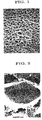
- the foam was then cut to have a cutting plane observed with an electric microscope. The texture thereof is shown in Figs. 1 and 2. It was observed in the foam of the present invention that the fibrous calcium titanate was not oriented in a uniform direction but rather was irregularly dispersed. Furthermore, measurement of the foam for the dielectric constant and dielectric loss tangent from multiple directions showed a generally constant dielectric constant and dielectric loss tangent within measurement error.
- Pre-expanded beads were prepared according to a similar method to that of Example 6 except that hexane instead of pentane, basic calcium carbonate instead of basic calcium triphosphate and dodecylbenzene sulfonate instead of sodium n-pallafin sulfonate were used.
- the pre-expanded beads were maintained at 40°C for 6 hours and fed into a pressure-resistant vessel, compressed by air pressure, and filled into a spherically shaped mold having a diameter of 320 mm at the compressibility of 36%. Steam having a vapor pressure of 1.0 kg f/cm 2 was then introduced into the mold so as to purge air from the mold.
- the specific gravity of the obtained foam was 0.153.
- the dielectric constant and dielectric loss tangent thereof were 1.49 and 0.0007 respectively.
- the foam was then cut to have a cutting plane observed with an electric microscope. It was observed that the fibrous calcium titanate was not oriented in a uniform direction but rather was irregularly dispersed. Furthermore, the measurement of the foam for the dielectric constant and dielectric loss tangent from multiple directions showed a generally constant dielectric constant and dielectric loss tangent within measurement error.
- Polyethylene (LDPE, density 0.922, MFR 1.1) (100 parts by weight), fibrous calcium titanate (same as that used in Example 2) (100 parts by weight), talc (1 parts by weight) and sodium carbonate (0.01 parts by weight) were fed into a biaxial extruder (trade name:KTX46, manufactured by Kobe Steel Ltd.) and melt-kneaded under the temperature of 170°C to prepare resin pellets having a particle size of 0.8 to 1.2 mm.
- the resin pellet was injection molded with an injection molding machine having a block mold of 320 ⁇ 20 ⁇ 60 mm, under the condition of the cylinder temperature of 170°C, injection pressure of 600 kgf/cm 2 and mold temperature of 40°C to prepare a block.
- the specific gravity of the obtained block was 1.48, the dielectric constant thereof was 8.5, and the dielectric loss tangent thereof was 0.0018.
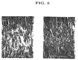
- the block was cut to have a cutting plane observed with an electric microscope. The texture is shown in Fig. 3. It was confirmed that the fibrous calcium titanate in the block was oriented.
- the block showed the above-mentioned value of dielectric properties in the orientation direction of the fibrous calcium titanate, whereas it showed different dielectric constant and dielectric loss tangent in a direction perpendicular to the orientation direction.
- the foam of the present invention is made up of a lightweight substance having uniform dielectric properties over all directions, and is therefore preferable for dielectric parts, specifically a lens for an antenna, and more specifically for a lens of a Luneberg lens antenna for tracking low-earth-orbit satellites.
- a spherical lens (foamed product) having a dielectric constant of 3.4 was prepared according to a similar method to that of Example 6, except that the amount of pentane to be charged during pre-expansion was 30 g, the pre-expanded beads having the expansion ratio of about 3 times was prepared, and the pre-expanded beads and a spherically shaped mold having a diameter of 450 mm were used.
- the lens was used for a receiving antenna as shown in Fig. 4, and in the measurement system as shown in Fig. 4, the gain value of the main beam that was transmitted from and received with a transmission antenna was measured. The result of the measurement is shown in Table 2.
- the lens was evaluated for its uniformity of the gain of the main beam as it was revolved on the x-y plane as shown in Fig. 4 through 360 degrees. It showed a uniform profile with substantially no error.
- a spherical lens having a dielectric constant of 3.4 was prepared according to a similar method to that of Example 8, except that particulate calcium titanate was used instead of fibrous calcium titanate and the amount of pentane to be charged during pre-expansion was 37 g.
- the gain of the main beam was measured under the same condition as that of Example 8 except that the lens was used for a receiving antenna as shown in Fig. 4. The result of the measurement is shown in Table 2.
- Example 8 In the same manner as Example 8, the lens was evaluated for its uniformity of the gain of the main beam as it was revolved on the x-y plane as shown in Fig. 4 through 360 degrees. It showed a large error of ⁇ 2.0 dB. Dielectric constant ( ⁇ r) Gain (d B ) Weight (kg) Example 8 3.4 29.4 38 Comparative Example 4 3.4 27.1 45
- the lens of the present invention is lightweight while it has high (large) gain.
- a spherical foam having a dielectric constant of 2.94 and a diameter of 370 mm was prepared according to a similar method to that of Example 6, except that the amount of the pentane to be charged during pre-expansion was 34 g, pre-expanded beads having an expansion ratio of about 3 times were prepared, and these pre-expanded beads and a mold having different shape were used.
- Two hemispherical shell foams each having a dielectric constant of 2.05, an outer diameter of 422 mm and an inner diameter of 370 mm were also prepared according to a similar method to that of Example 6, except that the amount of the pentane to be charged during pre-expansion was 56 g, pre-expanded beads having an expansion ratio of about 5 times were prepared, and these pre-expanded beads and a mold having different shape were used.
- two hemispherical shell foams each having a dielectric constant of 1.50, an outer diameter of 450 mm and an inner diameter of 422 mm were also prepared according to a similar method to that of Example 6 (materials and methods used herein were also the same as those in Example 6), except that a mold used had a different shape.
- the gain of the main beam was measured under the same condition as that of Example 8 except that the lens herein was used as a lens for a receiving antenna.
- the result of the measurement is shown in Table 3.
- the lens was evaluated for its uniformity of the gain of the main beam as it was revolved on the x-y plane as shown in Fig. 4 through 360 degrees. It showed a uniform profile with substantially no error.
- a spherical foam having a dielectric constant of about 2.94 and a diameter of 370 mm, two hemispherical shell foams each having a dielectric constant of about 2.05 an outer diameter of 422 mm and an inner diameter of 370 mm, and two hemispherical shell foams each having a dielectric constant of about 1.50, an outer diameter of 450 mm and an inner diameter of 422 mm, were prepared respectively according to a similar method to that of Example 9, except that particulate calcium titanate was used instead of fibrous calcium titanate and the amounts of the pentane to be charged during pre-expansion were 35 g, 59 g and 110 g respectively and pre-expanded beads each having expansion ratio of about 3 times, 5 times, 10 times were prepared respectively, and these pre-expanded beads were used respectively.
- pre-expanded beads each having expansion ratio of about 3 times, 5 times, 10 times were prepared respectively, and these pre-expanded beads were used respectively.
- the gain of the main beam was measured under the same condition as that of Example 9 except that the lens was used for a receiving antenna.
- the result of the measurement is shown in Table 3.
- Example 9 In the same manner as Example 9, the lens was evaluated for its uniformity of the gain of the main beam as it was revolved on the x-y plane as shown in Fig. 4 through 360 degrees. It showed a large error of ⁇ 1.5 dB.
- Example 9 370 422 450 370 422 2.94 2.05 1.50 29.8 14 Comparative Example 5 370 422 450 370 422 2.94 2.05 1.50 27.8 17
- the lens of the present invention is lightweight while it has high (large) gain.
- the dielectric foam resin according to the present invention has high and uniform dielectric properties, and therefore is preferably used as a dielectric material for a spherical lens, a Luneberg lens and the like.
Abstract
Description
- The present invention relates to a dielectric resin foam and a lens for radio waves using the same. More specifically, the present invention relates to a dielectric resin foam that has superior dielectric properties and is of a light weight, as well as being capable of being formed in a reduced size, enabling itself to be preferably used as a dielectric material for electronic devices in information and telecommunication fields such as an antenna, a condenser, a laminated circuit substrate, a connector, a memory and the like, and a lens for radio waves using the dielectric resin.
- The recent drastic increase in the amount of signal information transmitted by a radio wave, which resulted from the remarkable improvement of information and telecommunication technologies, requires better accuracy and swiftness of the signal information and further increase in the amount of information, as well as has caused a rapid movement to the use of high-frequency radio waves, which in turn realized a full-scale use of a high-frequency band such as of 1 GHz or more, specifically of 10 to 20 GHz, which was not used before.
- For example, for satellite communication, receiving and transmitting of radio waves are mainly performed by a parabola antenna with its antenna direction fixed, utilizing a stationary satellite. However, this transmission and receiving system can only handle a limited amount of information, which has caused a demand for a communication system capable of handling a larger amount of information. A recently established radio-wave communication system involves a lot of low-earth-orbit transfer satellites around the earth, through which radio waves are transmitted received, and a movable antenna located on the ground, which tracks the transfer satellites. This communication system has a superior advantage that every home user can transmit and receive a large amount of information through this system, which is comparable to an optical fiber.
- As a lens antenna used in a movable antenna system for tracking low-earth-orbit transfer satellites, a Luneberg lens antenna (a dome type antenna, i.e., an antenna comprising a Luneberg lens) is used. This antenna has an advantage that it can handle radio waves coming from or transmitted to multiple directions simultaneously, and therefore is most suitable for a movable antenna system for tracking low-earth-orbit transfer satellites.
- The Luneberg lens antenna includes a Luneberg lens which is capable of, for example, focusing radio waves. The lens used in this antenna is required to possess superior dielectric properties (e.g., high specific inductive capacity and low dielectric loss) so that it can handle a large amount of information, i.e. high-frequency radio waves, and to have a small dimension and low weight for workability and safety, since the antenna with this lens is installed on a roof of a domestic facility. For this, in Europe, the weight of a Luneberg lens antenna is officially standardized for installation works.
- Meanwhile, various dielectric resin compositions as dielectric materials with good fabrication properties that are required for bulk production have been proposed, each comprising a synthetic resin and a dielectric inorganic filler, so as to cope with downsizing, weight saving and performance improvement of dielectric parts, which make up electronic devices such as an antenna, a condenser, a laminated circuit substrate, a connector and a memory.
- For example, a dielectric resin composition comprising a synthetic resin and a powdery dielectric substance such as an alkaline earth metal titanate salt (e.g. barium titanate, strontium titanate, and barium strontium titanate) and the like has been known. A Luneberg lens using said dielectric resin composition has also been proposed (Japanese Patent Application Publication No. Sho-45-17242, Japanese Patent Application Publication No. Sho-56-17767). However, in order to obtain dielectric properties (high dielectric constant and low dielectric loss) that can cope with high-frequency radio waves by merely incorporating a powdery dielectric substance into a synthetic resin, a large amount of the powdery dielectric substance must be incorporated, which precludes those dielectric parts from having decreased weight and small dimension.
- A dielectric resin composition comprising a synthetic resin and a fibrous alkaline earth metal titanate salt and the like has also been proposed (for example, Japanese Patent Application Laid-open No. Hei-5-299871). The fibrous dielectric substance can provide dielectric properties capable of handling high-frequency radio waves, even if it is contained in an amount less than that of the powdery dielectric substance, and therefore can save the weight thereof by some extent. On the other hand, the fibrous dielectric substance has such a property as to be oriented in a uniform direction in the synthetic resin and shows different dielectric properties in the substance between the orientation direction and the direction perpendicular thereto. This property is not a major problem in practical use of the existing electronic devices. However, in the progress of using higher-frequency radio waves and developments of electronic devices matching thereto, the dielectric parts which constitute said devices are required to have higher and more uniform dielectric properties, and therefore further improvements thereof are desired.
- Furthermore, for example, Japanese Patent Laid-open No. Hei-8-133832 discloses a dielectric resin composition, in which a plate-like dielectric substance, which contains barium, titanium and rare earth elements as main components, is mixed in a synthetic resin. Since the plate-like dielectric substance, even if it is contained in an amount less than that of the powdery dielectric substance, can realize dielectric properties that can achieve a radio wave communication in a high frequency band, it contributes to weight saving by some extent in the same manner as done by the fibrous dielectric substance. However, the plate-like substance is also oriented in the synthetic resin, although the orientation does not extend to such a degree as the fibrous substance. This orientation of the substance may cause an ununiform dielectric profile, and therefore there still remains the necessity for improvement for the purpose of providing more uniform dielectric properties.
- On the other hand, Japanese Patent Application Laid-open No. Hei-7-320537 discloses a dielectric polyurethane foam obtained by incorporating a powdery alkaline earth metal titanate into polyurethane and expanding the mixture. However, in order to enhance the dielectric characteristic of said foam to such an extent as to render a high-frequency radio wave usable, a large amount of powdery dielectric substance must be incorporated. This prevents downsizing and weight saving. Moreover, a large amount of powdery dielectric substance incorporated causes the mechanical strength of a resulting foam to be substantially decreased, which makes the foam impractical.
- Therefore, the present inventors conducted intensive studies to solve the above-mentioned problems of the conventional arts, and succeeded in obtaining a novel dielectric resin foam, through which the present invention has been conceived.
- Namely, the present invention relates to a dielectric resin foam obtained by expanding a dielectric resin composition comprising a synthetic resin and a fibrous and/or plate-like dielectric inorganic filler.
- As used herein, by the fibrous and/or plate-like dielectric inorganic filler is meant one of or both of the fibrous dielectric inorganic filler and plate-like inorganic filler.
- The present inventors have found that, when the dielectric resin composition is expansion molded into such as spherical shape after the fibrous or plate-like dielectric inorganic filler has been incorporated into the synthetic resin, rather than the filler is not merely incorporated in the synthetic resin, the plate-like or fibrous dielectric inorganic filler is not oriented in a uniform direction in the synthetic resin but is dispersed ununiformly, hence enabling a resin foam to have not only a superior dielectric properties but also uniform dielectric properties.
- Therefore, the dielectric resin foam of the present invention has superior dielectric properties that can cope with high-frequency radio waves, i.e., those with high dielectric constant, low dielectric loss and the like, and has quite uniform dielectric properties. Furthermore, since the foam is of a lightweight, it can be miniaturized. Moreover, since the foam comprises a fibrous and/or plate-like dielectric inorganic filler, it has high mechanical strength and heat resistance.
- The dielectric resin foam of the present invention can be preferably used as a material for various dielectric parts of electronic devices relating to information and telecommunication technologies such as an antenna, a condenser, a laminated circuit substrate, a connector and a memory.
- Furthermore, a lens made of the dielectric resin foam of the present invention has been miniaturized and weight saved while possessing high and uniform dielectric properties. This lens is formed into a spherical shape or a Luneberg-lens like shape (each includes hemispherical shape), so that radio waves transmitted to and received from all directions can be focused or diffused smoothly without electric wave hindrance.
- As used herein, the Luneberg lens is of a spherical shape (including hemispherical type) with multiple layers having different specific inductive capacities concentrically overlapped to each other, thereby forming a concentric sphere. The layers are generally formed so that a peripheral layer has a lower dielectric constant.
- For example, a Luneberg lens which is equipped in a Luneberg lens antenna for tracking a low-earth-orbit satellite may have a dielectric constant of not less than 1.5 at 12 GHz and 25°C and a specific gravity of not more than 0.5, and preferably a dielectric constant of not less than 2.0 and a specific gravity of not more than 0.5 under the above condition. The thus formed lens can cope with a high frequency band of not less than 10 GHz, specifically in the range of 12 to 20 GHz. Since the lens has such superior dielectric properties and low specific gravity, it can be miniaturized and weight-saved, for example, it may have a diameter of about 10 to 30 cm and a weight of about several kilograms.
-
- Fig. 1 shows an electric microscope photograph (100 magnifications) as an alternative to a figure, which shows the state of dispersion of the dielectric inorganic filler on the cutting plane of the dielectric resin foam according to the present invention (Example 6).
- Fig. 2 shows the same electric microscope photograph as above (1000 magnifications).
- Fig. 3 shows an electric microscope photograph (1500 magnifications) as an alternative to a figure, which shows the state of dispersion of the dielectric inorganic filler on the cutting plane of the dielectric resin molded form according to Comparative Example 3.
- Fig. 4 is a schematic view which shows an apparatus for measurement of gain values of main beams in Examples 8 and 9, and Comparative Examples 4 and 5.
-
- A synthetic resin used for the present invention is not specifically limited, and various thermoplastic resins and thermosetting resins can be used. Specific examples of the thermoplastic resin include, for example, polyethylene, polypropylene, polyisoprene, chlorinated polyethylene, polyvinyl chloride, polybutadiene, polystyrene, high impact polystyrene, acrylonitrile-styrene resin (AS resin), acrylonitrile-butadiene-styrene resin (ABS resin), methyl methacrylate-butadiene-styrene resin (MBS resin), methyl methacrylate-acrylonitrile-butadiene-styrene resin (MABS resin), acrylonitrile-acrylic rubber-styrene resin (AAS resin), acrylic resin, polyester (polyethylene terephthalate, polybutylene terephthalate, polyethylene naphthalate and the like), polycarbonate, polyphenylene ether, modified polyphenylene ether, aliphatic polyamide, aromatic polyamide, polyphenylene sulfide, polyimide, polyether ether ketone, polysulfone, polyarylate, polyether ketone, polyether nitrile, polythioether sulfone, polyether sulfone, polybenzimidazole, polyamideimide, polyetherimide, liquid crystalline polymer and the like. Of these resins, polyethylene, polypropylene, polystyrene, acrylic resin and the like are preferred in light of expansion forming properties, dielectric properties (specifically low dielectric loss) and the like. One of the thermoplastic resins may be used solely, or the mixture of two or more of them may optionally be used. The specific examples of the thermosetting resin include, for example, polyurethane, phenol resin, melamine resin, urea resin, unsaturated polyester resin, diallylphthalate resin, silicone resin, epoxy resin (bisphenol A type epoxy resin, bisphenol F type epoxy resin, bisphenol AD type epoxy resin, phenol novolak type epoxy resin, cresol novolak type epoxy resin, cyclic aliphatic epoxy resin, glycidyl ester epoxy resin, glycidyl amine epoxy resin, heterocyclic epoxy resin, urethane modified epoxy resin, brominated bisphenol A type epoxy resin) and the like. Of these resins, silicone resin, polyurethane, epoxy resin and the like are preferred. One of the thermosetting resins may be used solely, or the mixture of two or more of them may optionally be used.
- In the present invention, among the synthetic resins, thermoplastic resins are preferably used in light of the fabrication properties and the like.
- For example, when the dielectric resin foam of the present invention is used for a lens, specifically a spherical lens or Luneberg lens, a thermoplastic resin is preferable when considering moldability, dielectric properties, weather resistance and the like, and of which, polyolefins such as polyethylene, polypropylene, polystyrene and the like are specifically preferred.
- The fibrous or plate-like dielectric inorganic filler which is incorporated into the synthetic resin may include, for example, a filler having a composition represented by the general formula: MO • nTiO2 (wherein M is one or more divalent metal(s) and n is an integer of not less than 1) and having a fibrous or plate-like shape.
- The divalent metal which is represented by M in the above-mentioned general formula include, and not specifically limited to, as long as the oxide shows dielectric properties, for example, alkaline earth metals such as barium, strontium, calcium, magnesium and the like, and lead and the like. The term "plate-like" shape also includes "scaly", "micaceous", "flaky" and the like shape.
- For both the fibrous alkaline earth metal titanate salt and fibrous lead titanate, any of the known substances may be used.
- The plate-like alkaline earth metal titanate salt and plate-like lead titanate can be produced, for example, by reacting a mixture of plate-like titanium oxide with one or more of salt(s) such as an oxide, a hydroxide, an inorganic acid salt, an organic acid salt and the like of the alkaline earth metal or lead, under the temperature of 500 to 1400°C, or by other methods. The plate-like titanium oxide, one of the raw materials, can be produced by known methods described in, for example, Japanese Patent Application Publication No. Hei-6-88786, Japanese Patent Application Laid-open No. Hei-5-221795, and Japanese Patent Application Laid-open No. Hei-10-95617. The reaction of the plate-like titanium oxide with alkaline earth metal salt or lead salt can be carried out following a similar procedure to that of the reaction of the fibrous titanium oxide with the alkaline earth metal salt or lead salt (as mentioned below). The reaction of the fibrous titanium oxide with the alkaline earth metal salt or lead salt is known, and can be carried out following, for example, a hydrothermal method, baking method, wet deposition baking method, flux method and the like.
- The specific examples of the fibrous or plate-like alkaline earth metal titanate salt and lead titanate may include, for example, barium titanate, calcium titanate, magnesium titanate, strontium titanate, barium strontium titanate, barium calcium titanate, calcium strontium titanate, lead titanate and the like, each of which has a fibrous or plate-like shape. These may be a composition material with other ceramic materials such as titanium oxide. Of them, calcium titanate is preferably used since it has low dielectric loss at the high frequency band. One of the fibrous and plate-like alkaline earth metal titanates, or fibrous or plate-like lead titanate may be used solely, or two or more of them may be used in combination. Furthermore, the fibrous and plate-like ones may used in combination.
- Although the size of the fibrous dielectric inorganic filler is not specifically limited, the fibrous filler generally having a mean fiber diameter of about 0.01 to 1 µm, preferably of about 0.05 to 0.5 µm, a mean fiber length of about 0.5 to 100 µm, preferably of about 3 to 50 µm and an aspect ratio (mean fiber length/mean fiber diameter) of not less than 5, preferably of not less than 10 may be used. Also, although the size of the plate-like dielectric inorganic filler is not specifically limited, the plate-like filler having a mean long diameter of about 0.5 to 100 µm, preferably of about 1 to 20 µm, a mean short diameter of about 0.2 to 100 µm, preferably of about 0.5 to 20 µm, a mean thickness of about 0.01 to 10 µm, preferably of about 0.05 to 5 µm and an aspect ratio (mean long diameter/mean thickness) of about 3 to 100, preferably of about 5 to 50 may be used.
- The amount of the fibrous and/or plate-like dielectric inorganic filler to be incorporated into the synthetic resin is not specifically limited, and it may be suitably selected from the wide range, depending on the various conditions such as the kind of the synthetic resin, the kind(s) of the fibrous and/or plate-like inorganic filler and the shape thereof (including sole use of the fibrous or plate-like filler, or combination use thereof), the application of the obtained material, the kind(s) of the resin additives which is(are) optionally incorporated into the resin and the amount of additive(s) to be incorporated, and the like. For example, the fibrous and/or plate-like dielectric inorganic filler in an amount of generally 30 to 80 wt%, preferably 45 to 75 wt% of the total amount of the dielectric resin composition is preferably incorporated into the resin in light of the easiness of setting of the dielectric constant within the preferred range (a range wherein the dielectric constant at 12 GHz, 25°C is not less than 1.5, specifically not less than 2.0) and obtaining the fabrication properties and expansion properties (including expansion handling properties during working) and the like.
- The dielectric resin foam of the present invention can be produced by mixing a synthetic resin, a fibrous and/or plate-like dielectric inorganic filler and optionally a resin additive to have a dielectric resin composition, and expansion forming the dielectric resin composition into spherical or the like shape.
- The resin additive may be incorporated into the resin, as long as it does not deteriorate the preferred properties of the dielectric resin foam of the present invention and does not disturb a subsequent expansion procedure. As the resin additive, any additives which have been conventionally incorporated into synthetic resins may be used, which include, for example, a heat stabilizer (e.g., phosphorous acid, hindered phenol, phosphate), a lubricant, a release agent, a dye and a pigment (e.g., chromium yellow), an ultraviolet absorber (for example, benzotriazole ultraviolet absorber), a flame retardant (e.g., phosphazene, phosphate ester), a lubricant, a filler (e.g., titanium dioxide, calcium carbonate, talc) and the like. Two or more of these resin additives may be used in combination.
- Furthermore, in the present invention, the powdery dielectric substance which has been conventionally used may also be incorporated into the resin in addition to the fibrous and/or plate-like dielectric inorganic filler within such a range as not to deteriorate the preferred properties of the dielectric resin foam of the present invention.
- The mixing of the synthetic resin, fibrous and/or plate-like dielectric inorganic filler, resin additive and the like can be carried out following known methods, for example, the materials may be mixed with various mixing apparatus such as a biaxial extruder, a uniaxial screw extruder, a co-kneader, a multiaxial screw extruder, a kneader, a mixing roll, a stirrer, a Banbury mixer and the like.
- The method for expansion forming the thus-obtained dielectric resin composition into spherical or the like shape is not specifically limited, and can be carried out by any methods such as heat decomposition expansion method, beads expansion method, supercritical fluid method and the like.
- Heat decomposition expansion using thermal decomposition type compound is preferably used since it is an easy and low-cost method. When a thermal decomposition type compound, i.e. an expansion agent is used, the expansion is carried out by mixing the expansion agent with the synthetic resin, fibrous and/or plate-like dielectric inorganic filler, resin additive and the like, filling the obtained resin composition into a suitable mold having spherical or the like shape and heating under pressure or without pressure. A known agent may be used as the expansion agent, and may include, for example, ADCA (azodicarboxylicamide), OBSH (p,p'-oxybisbenzenesulfonylhydrazide), DPT (dinitropentamethylenetetramine), TSH (p-toluenesulfonylhydrazide), BSH (benzenesulfonylhydrazide), and salts such as calcium salt, aluminum salt, barium salt, strontium salt and the like thereof, sodium bicarbonate, monosodium citric anhydride and the like. Of them, ADCA is preferable for use, since it can provide uniform and fine foam and is also advantageous in keeping material strength and low dielectric loss tangent. The amount of the expansion agent to be used is generally 1 to 20 parts by weight, preferably 3 to 10 parts by weight per 100 parts by weight of the unexpanded material. During the heat decomposition expansion, various adjuvants may be used for the purposes of adjusting the expansion rate, preventing deterioration of the material and the like. Such adjuvants include, for example, tribasic lead sulfate, dibasic phosphite salt, lead stearate, zinc stearate, zinc carbonate, zinc oxide, barium stearate, aluminum stearate, calcium stearate, dibutyltin malate, urea, maleic acid and the like.
- Although the expansion ratio of the foam obtained by using a thermal decomposition expansion agent is not specifically limited, the expansion may be carried out generally with the expansion ratio of about 2 to 20 times, preferably about 5 to 15 times, when considering the decrease of strength due to the plastic deformation of the obtained material or weight saving and the like.
- Furthermore, a bead expansion process is effective in producing the foam of the present invention. In the present invention, the expansion of beads can be carried out following a known method. For example, the dielectric resin foam of the present invention can be produced by melt-kneading a synthetic resin and a fibrous and/or plate-like dielectric inorganic filler to have particles (beads) having desired shape, pre-expanding the particles to have pre-expanded particles, optionally subjecting the particles to a temperature between room temperature and a temperature higher than room temperature by about 10 to 30°C for about several hours, filling the particles into a mold having spherical or the like shape, and heating the particles either under pressure or without pressure to heat fuse and expansion mold the pre-expanded particles.
- In order to melt-knead the synthetic resin and fibrous and/or plate-like dielectric inorganic filler, the above-mentioned general mixing apparatus may be used. The particles that are obtained by melt-kneading is not specifically limited in shape, and may be of a desired shape, for example, a cylindrical shape, an elliptical spherical shape, a spherical shape, a cubic shape, a cuboid shape, a tetrapot shape and the like. Although the particles is not limited in size, the particle size may generally be about 0.05 to 5 mm, preferably about 0.1 to 3 mm, when considering workability, any other properties such as mechanical strength of the resultant lens such as a Luneberg lens. During melt-kneading of the synthetic resin and fibrous and/or plate-like dielectric inorganic filler, a suitable amount of the other resin additives may be incorporated. These resin additives may include, for example, an air bubble regulator such as talc powder, a nucleus agent such as sodium carbonate, an antioxidant, a heat stabilizer, an ultraviolet absorber, a lubricant, a release agent, a dye, a pigment, an antistatic agent, a filler and the like. One of the resin additives may be used solely or two or more of them may be used in combination.
- The pre-expansion of the particles of the synthetic resin and fibrous and/or plate-like dielectric inorganic filler can also be carried out by known methods. For example, a water dispersion of the particles is mixed with a volatile expansion agent to have a mixture, which is then hot-mixed under pressure in a pressure-resistant vessel such as an autoclave to impregnate the particles with the volatile expansion agent. The particles which have been impregnated with the volatile expansion agent are then released into a space in which the pressure is lower than that of the pressure-resistant vessel or into the atmosphere, thus causing expansion to have the pre-expanded particles.
- During dispersion of the particles of the synthetic resin and fibrous and/or plate-like dielectric inorganic filler into water, as a dispersing agent, for example, basic calcium triphosphate, basic magnesium carbonate, calcium carbonate and the like, and as a dispersion aid, for example, sodium dodecylbenzenesulfonate, sodium n-pallafin sulfonate, sodium α-olefin sulfonate and the like, may be incorporated. Although the amounts of the dispersing agent and dispersion aid to be incorporated are not specifically limited and may be suitably selected from the wide range depending on the conditions such as the kind of the synthetic resin, the shape and kind of the dielectric inorganic filler and the like, while generally, about 0.1 to 5 parts by weight of the dispersing agent and about 0.001 to 3 parts by weight of the dispersion aid per 100 parts by weight of water may be incorporated.
- As the volatile expansion agent, any agents generally used in expansion of beads may be used, and may include, for example, aliphatic hydrocarbons such as propane, butane, isobutane, pentane and hexane, alicyclic hydrocarbons such as cyclobutane, cyclopentane and cyclohexane, lower alcohols such as methanol, ethanol, propanol, isopropanol and butanol, halogenated hydrocarbons such as methyl chloride, methylene dichloride, ethyl chloride, trichlorotrifluoromethane, dichlorodifluoromethane, dichlorotetrafluoroethane and trichlorotrifluoromethane, inert gas such as carbon dioxide and nitrogen. One of the volatile expansion agents may be used solely, or two or more of them may be used in combination. Although the amount of the volatile expansion agent to be used is not specifically limited, and may be suitably selected from the wide range depending on set expansion ratios of the pre-expanded particles to be obtained and subsequently produced foam, kind of the synthetic resin, kind and shape of the dielectric inorganic filler, the shape and size of the particles to be pre-expanded and the like, it may be generally about 1 to 80 parts by weight, preferably about 5 to 60 parts by weight, regarding the total weight of the synthetic resin in the particles to be pre-expanded as 100 parts by weight.
- In order to impregnate the particles with the volatile expansion agent, the particles may be subjected to heating at about 100 to 150°C under the pressure of about 10 to 50 kgf/cm2, for generally about 30 minutes. The particles which have been impregnated with the volatile expansion agent are then released, for example, through an orifice pore which has a diameter of about 1 to 10 mm and is provided at the tip of a cap of the pressure-resistant vessel to the air to have the pre-expanded particles. Although the expansion ratio of the pre-expanded particles is not specifically limited, it may be generally about 2 to 100 times, preferably about 5 to 70 times, when considering such as the expansion moldability in the next step.
- The pre-expanded particles may be optionally subjected to a temperature between room temperature and a temperature higher than the room temperature by about 10 to 30°C for about several hours, then filled into a mold, heated and expansion molded. The filling of the pre-expanded particles into the mold can be carried out by the known methods. For example, the pre-expanded particles may be forced to be delivered to the mold with pressured air. A heating manner is also employed. For example, heating may be achieved by feeding steam of about 0.5 to 5 kgf/cm2, preferably about 1.0 to 3.5 kgf/cm2 into a mold. The heating time may be generally about several seconds to about several minutes, preferably about 10 to 60 seconds. After the expansion molding is finished, the particles may be cooled by means of water-cooling, air-cooling and the like. As such, the foam of the present invention can be produced by beads expansion method.
- Furthermore, the expansion method using supercritical fluid may include impregnating a mixture of a resin and a fibrous and/or plate-like dielectric inorganic filler with supercritical carbonic gas and reducing the pressure quickly.
- The dielectric resin foam of the present invention may be expansion molded in a mold as described above or shaped by a general process such as cutting after the expansion so as to have a foamed product having a desired shape.
- The dielectric resin foam of the present invention may be of a hollow spherical shape (spherical shell shape). Furthermore, the dielectric resin foam of the present invention may be of a spherical shape with multilayer structure, in which two or more layers having different specific inductive capacities are concentrically overlapped to each other, thereby forming a concentric sphere (i.e., Luneberg-lens like shape).
- When the dielectric resin foam of the present invention is used for a spherical lens or Luneberg lens, the foam in block form may be produced, cut and processed into a desired shape (for example, spherical shape, spherical shell shape, hemispherical shell shape and the like). However, forming of the dielectric resin into a spherical shape or any other desirable shapes is preferably achieved by using a mold having the desired shape and allowing the resin to be expansion molded into the desired shape within the mold.
- Forming of the foam into a Luneberg-lens like shape may be made by combining a spherically shaped member (including a hemispherically shaped member) and multiple (or single) spherical shell member(s) (hollow spherical member) having different specific inductive capacities with respect to each other and to the spherically shaped intermediate.
- Hereinafter the present invention is exemplified in more detail with reference to the Examples and Comparative Examples.
- To polyethylene (LDPE, density 0.922, MFR 1.1, 100 parts by weight) were added azodicarbon amide (expansion agent, 5 parts by weight), plate-like calcium titanate (100 parts by weight) and dicumyl peroxide (crosslinking agent, 0.7 parts by weight), and the mixture was melt-kneaded with a mixing roll at 130°C, followed by pressing to have an expandable uncrosslinked sheet having a thickness of 3 mm.
- The obtained expandable uncrosslinked sheet was put into a gear oven which had been heated to 160°C, and heated until the expansion ratio reached about 5 times, allowing the resin to be crosslinked and expanded. Thus, a foam having an expansion ratio of about 5 times was obtained.
- A foam having an expansion ratio of about 5 times was prepared according to a similar method to that of Example 1 except that fibrous calcium titanate was used instead of the plate-like calcium titanate.
- A foam having an expansion ratio of about 5 times was prepared according to a similar method to that of Example 1 except that the plate-like calcium titanate was not added.
- A foam having an expansion ratio of about 5 times was prepared according to a similar method to that of Example 1 except that powdery calcium titanate was used instead of the plate-like calcium titanate.
- The specific gravity, dielectric constant and dielectric loss tangent were measured for the foams obtained in the above-mentioned Examples 1 and 2 and Comparative Examples 1 and 2. The measurements were made at 25°C, 12 GHz and by wave guide tube method respectively, and the condition was similar for the following Examples and Comparative Examples. The results are shown in Table 1.
Inorganic Filler Amount to be Incorporated Specific Gravity Dielectric constant (ε r) Dielectric Loss Tangent (tan δ) Expansion Ratio Example 1 plate-like calcium titanate 100 0.298 1.91 0.0007 5 times Example 2 fibrous calcium titanate 100 0.298 1.87 0.0009 5 times Comparative Example 1 - 0 0.184 1.24 0.0005 5 times Comparative Example 2 powdery calcium titanate 100 0.299 1.76 0.001 5 times - The dimensional properties of the fibrous or plate-like alkaline earth metal titanate salt in the table are as follows.
Example 1: plate-like calcium titanate having a mean long diameter of 8 µm, a mean short diameter of 5 µm, a mean thickness of 1.0 µm and an aspect ratio (mean long diameter/mean thickness) of 8.
Example 2: fibrous calcium titanate having a mean fiber diameter of 0.5 µm, a mean fiber length of 7 µm and an aspect ratio (mean fiber length /mean fiber diameter) of 14.
Comparative Example 2: powdery calcium titanate having a mean particle size of 1 µm. - As is apparent from Table 1, the foams of the present invention have a high dielectric constant, even though they contain the same amount of dielectric inorganic filler and have the same expansion ratio as that of the Comparative Examples.
- A foam having an expansion ratio of about 5 times was prepared according to a similar method to that of Example 1 except that plate-like barium titanate (a mean long diameter of 10 µm, a mean short diameter of 6 µm, a mean thickness of 1.2 µm and an aspect ratio (mean long diameter/mean thickness) of 8.3) (200 parts by weight ) was used instead of the plate-like calcium titanate.
- The specific gravity of the obtained foam was 0.417. The dielectric constant and dielectric loss tangent thereof were 2.62 and 0.0130 respectively.
- A foam having an expansion ratio of about 5 times was prepared according to a similar method to that of Example 1 except that plate-like strontium titanate (having a mean long diameter of 10 µm, a mean short diameter of 5 µm, a mean thickness of 1.1 µm and an aspect ratio (mean long diameter/mean thickness) of 9) (200 parts by weight) was used instead of the plate-like calcium titanate.
- The specific gravity of the obtained foam was 0.401. Furthermore, the dielectric constant and dielectric loss tangent thereof were 2.37 and 0.0008 respectively.
- A foam having an expansion ratio of about 5 times was prepared according to a similar method to that of Example 1 except that fibrous calcium strontium titanate (having a mean fiber diameter of 0.6 µm, a mean fiber length of 6 µm and an aspect ratio (mean fiber length/mean fiber diameter) of 10) (200 parts by weight) was used instead of the plate-like calcium titanate.
- The specific gravity of the obtained foam was 0.394. Furthermore, the dielectric constant and dielectric loss tangent thereof were 2.59 and 0.0006 respectively.
- Polyethylene (LDPE, density 0.922, MFR 1.1) (100 parts by weight), fibrous calcium titanate (same as that used in Example 2, 100 parts by weight), talc (1 parts by weight) and sodium carbonate (0.01 parts by weight) were fed into a biaxial extruder (trade name:KTX46, manufactured by Kobe Steel Ltd.) and melt-kneaded under the temperature of 170°C to prepare resin beads having particle size of 0.8 to 1.2 mm (pellets to be expanded are referred to "beads").
- The resin beads (1500 g), ion exchanged water (3000 g), pentane (100 g), basic calcium triphosphate (20 g) and sodium n-pallafin sulfonate (0.3 g) were charged in an autoclave (5 liter volume) equipped with a valve at the lower portion thereof, which can release the contents to the outside with keeping the internal pressure, and maintained at 120°C for 2 hours to impregnate the resin beads with pentane. The pentane-impregnated resin beads were released under the atmospheric pressure, from the valve at the lower portion of the autoclave, through an orifice plate having a pore diameter of 4.4 mm and expanded to prepare pre-expanded beads having an expansion ratio of about 10 times.
- The pre-expanded beads were maintained at 35°C for 6 hours and put into a pressure-resistant vessel, compressed by air pressure, and filled into a block mold of 320×320×60 mm at the compressibility of 36%.
- Steam having a vapor pressure of 1.0 kgf/cm2 was then introduced into the mold so as to purge air from the mold. Steam having the same vapor pressure as above was then introduced thereinto for 30 seconds, and the filled, pre-expanded beads were expansion molded and then cooled. The molded article that had been taken from the mold was cure dried under the temperature of 80°C for 20 hours. Thus, a foam having good surface appearance was prepared.
- The specific gravity of the obtained foam was 0.150. The dielectric constant and dielectric loss tangent thereof were 1.52 and 0.0006 respectively.
- The foam was then cut to have a cutting plane observed with an electric microscope. The texture thereof is shown in Figs. 1 and 2. It was observed in the foam of the present invention that the fibrous calcium titanate was not oriented in a uniform direction but rather was irregularly dispersed. Furthermore, measurement of the foam for the dielectric constant and dielectric loss tangent from multiple directions showed a generally constant dielectric constant and dielectric loss tangent within measurement error.
- Pre-expanded beads were prepared according to a similar method to that of Example 6 except that hexane instead of pentane, basic calcium carbonate instead of basic calcium triphosphate and dodecylbenzene sulfonate instead of sodium n-pallafin sulfonate were used. The pre-expanded beads were maintained at 40°C for 6 hours and fed into a pressure-resistant vessel, compressed by air pressure, and filled into a spherically shaped mold having a diameter of 320 mm at the compressibility of 36%. Steam having a vapor pressure of 1.0 kg f/cm2 was then introduced into the mold so as to purge air from the mold. Furthermore, steam having the same vapor pressure as above was introduced thereinto for 30 seconds, and the filled, pre-expanded beads were expansion molded and then cooled. The molded article that had been taken from the mold was cure dried under the temperature of 80°C for 20 hours. Thus, a spherical foam having good surface appearance was prepared.
- The specific gravity of the obtained foam was 0.153. The dielectric constant and dielectric loss tangent thereof were 1.49 and 0.0007 respectively.
- The foam was then cut to have a cutting plane observed with an electric microscope. It was observed that the fibrous calcium titanate was not oriented in a uniform direction but rather was irregularly dispersed. Furthermore, the measurement of the foam for the dielectric constant and dielectric loss tangent from multiple directions showed a generally constant dielectric constant and dielectric loss tangent within measurement error.
- Polyethylene (LDPE, density 0.922, MFR 1.1) (100 parts by weight), fibrous calcium titanate (same as that used in Example 2) (100 parts by weight), talc (1 parts by weight) and sodium carbonate (0.01 parts by weight) were fed into a biaxial extruder (trade name:KTX46, manufactured by Kobe Steel Ltd.) and melt-kneaded under the temperature of 170°C to prepare resin pellets having a particle size of 0.8 to 1.2 mm.
- The resin pellet was injection molded with an injection molding machine having a block mold of 320×20×60 mm, under the condition of the cylinder temperature of 170°C, injection pressure of 600 kgf/cm2 and mold temperature of 40°C to prepare a block. The specific gravity of the obtained block was 1.48, the dielectric constant thereof was 8.5, and the dielectric loss tangent thereof was 0.0018.
- The block was cut to have a cutting plane observed with an electric microscope. The texture is shown in Fig. 3. It was confirmed that the fibrous calcium titanate in the block was oriented.
- The block showed the above-mentioned value of dielectric properties in the orientation direction of the fibrous calcium titanate, whereas it showed different dielectric constant and dielectric loss tangent in a direction perpendicular to the orientation direction.
- As is apparent from the Examples 6 and 7 and Comparative Example 3, the foam of the present invention is made up of a lightweight substance having uniform dielectric properties over all directions, and is therefore preferable for dielectric parts, specifically a lens for an antenna, and more specifically for a lens of a Luneberg lens antenna for tracking low-earth-orbit satellites.
- A spherical lens (foamed product) having a dielectric constant of 3.4 was prepared according to a similar method to that of Example 6, except that the amount of pentane to be charged during pre-expansion was 30 g, the pre-expanded beads having the expansion ratio of about 3 times was prepared, and the pre-expanded beads and a spherically shaped mold having a diameter of 450 mm were used. The lens was used for a receiving antenna as shown in Fig. 4, and in the measurement system as shown in Fig. 4, the gain value of the main beam that was transmitted from and received with a transmission antenna was measured. The result of the measurement is shown in Table 2.
- The lens was evaluated for its uniformity of the gain of the main beam as it was revolved on the x-y plane as shown in Fig. 4 through 360 degrees. It showed a uniform profile with substantially no error.
- A spherical lens having a dielectric constant of 3.4 was prepared according to a similar method to that of Example 8, except that particulate calcium titanate was used instead of fibrous calcium titanate and the amount of pentane to be charged during pre-expansion was 37 g. The gain of the main beam was measured under the same condition as that of Example 8 except that the lens was used for a receiving antenna as shown in Fig. 4. The result of the measurement is shown in Table 2.
- In the same manner as Example 8, the lens was evaluated for its uniformity of the gain of the main beam as it was revolved on the x-y plane as shown in Fig. 4 through 360 degrees. It showed a large error of ±2.0 dB.
Dielectric constant (ε r) Gain (dB) Weight (kg) Example 8 3.4 29.4 38 Comparative Example 4 3.4 27.1 45 - As is apparent from Example 8 and Comparative Example 4, the lens of the present invention is lightweight while it has high (large) gain.
- A spherical foam having a dielectric constant of 2.94 and a diameter of 370 mm was prepared according to a similar method to that of Example 6, except that the amount of the pentane to be charged during pre-expansion was 34 g, pre-expanded beads having an expansion ratio of about 3 times were prepared, and these pre-expanded beads and a mold having different shape were used. Two hemispherical shell foams each having a dielectric constant of 2.05, an outer diameter of 422 mm and an inner diameter of 370 mm were also prepared according to a similar method to that of Example 6, except that the amount of the pentane to be charged during pre-expansion was 56 g, pre-expanded beads having an expansion ratio of about 5 times were prepared, and these pre-expanded beads and a mold having different shape were used. Furthermore, two hemispherical shell foams each having a dielectric constant of 1.50, an outer diameter of 450 mm and an inner diameter of 422 mm were also prepared according to a similar method to that of Example 6 (materials and methods used herein were also the same as those in Example 6), except that a mold used had a different shape.
- Those foams were combined together to produce a Luneberg lens made up of three layers.
- The gain of the main beam was measured under the same condition as that of Example 8 except that the lens herein was used as a lens for a receiving antenna. The result of the measurement is shown in Table 3.
- In the same manner as Example 8, the lens was evaluated for its uniformity of the gain of the main beam as it was revolved on the x-y plane as shown in Fig. 4 through 360 degrees. It showed a uniform profile with substantially no error.
- A spherical foam having a dielectric constant of about 2.94 and a diameter of 370 mm, two hemispherical shell foams each having a dielectric constant of about 2.05 an outer diameter of 422 mm and an inner diameter of 370 mm, and two hemispherical shell foams each having a dielectric constant of about 1.50, an outer diameter of 450 mm and an inner diameter of 422 mm, were prepared respectively according to a similar method to that of Example 9, except that particulate calcium titanate was used instead of fibrous calcium titanate and the amounts of the pentane to be charged during pre-expansion were 35 g, 59 g and 110 g respectively and pre-expanded beads each having expansion ratio of about 3 times, 5 times, 10 times were prepared respectively, and these pre-expanded beads were used respectively. These forms were combined together to produce a Luneberg lens made up of three layers.
- The gain of the main beam was measured under the same condition as that of Example 9 except that the lens was used for a receiving antenna. The result of the measurement is shown in Table 3.
- In the same manner as Example 9, the lens was evaluated for its uniformity of the gain of the main beam as it was revolved on the x-y plane as shown in Fig. 4 through 360 degrees. It showed a large error of ±1.5 dB.
Outer Diameter
(mm)Inner Diameter (mm) Dielectric constant Gain
(dB)Weight (kg) 1st
layer2nd
layer3rd
layer2nd layer 3rd
layer1st
layer2nd layer 3rd
layerExample 9 370 422 450 370 422 2.94 2.05 1.50 29.8 14 Comparative Example 5 370 422 450 370 422 2.94 2.05 1.50 27.8 17 - As is apparent from Example 9 and Comparative Example 5, the lens of the present invention is lightweight while it has high (large) gain.
- As mentioned above, the dielectric foam resin according to the present invention has high and uniform dielectric properties, and therefore is preferably used as a dielectric material for a spherical lens, a Luneberg lens and the like.
Claims (5)
- A dielectric resin foam obtained by expanding a resin composition comprising a synthetic resin and at least one of a fibrous dielectric inorganic filler and a plate-like dielectric inorganic filler.
- The dielectric resin foam according to claim 1, wherein said at least one of said fibrous dielectric inorganic filler and said plate-like dielectric inorganic filler is at least one of fibrous alkaline earth metal titanate and plate-like alkaline earth metal titanate.
- The dielectric resin foam according to claim 1 or 2, which has a dielectric constant of not less than 1.5 at 12 GHz and 25°C.
- A lens for radio waves comprising the dielectric resin foam according to any one of claims 1 to 3, which has a constant dielectric constant and a spherical shape.
- A lens for radio waves comprising the dielectric resin foam according to any one of claims 1 to 3, said dielectric resin foam being formed into a Luneberg lens, said Luneberg lens having a spherical shape and multiple layers each having a different dielectric constant, said multiple layers being concentrically overlapped to each other, thereby forming a concentric sphere.
Applications Claiming Priority (5)
| Application Number | Priority Date | Filing Date | Title |
|---|---|---|---|
| JP2000227971 | 2000-07-27 | ||
| JP2000227971 | 2000-07-27 | ||
| JP2001222685A JP3638889B2 (en) | 2000-07-27 | 2001-07-24 | Dielectric resin foam and radio wave lens using the same |
| JP2001222685 | 2001-07-24 | ||
| PCT/JP2001/006407 WO2002010266A1 (en) | 2000-07-27 | 2001-07-25 | Dielectric resin foam and lens antenna comprising the same |
Publications (3)
| Publication Number | Publication Date |
|---|---|
| EP1310518A1 true EP1310518A1 (en) | 2003-05-14 |
| EP1310518A4 EP1310518A4 (en) | 2005-03-16 |
| EP1310518B1 EP1310518B1 (en) | 2008-01-23 |
Family
ID=26596863
Family Applications (1)
| Application Number | Title | Priority Date | Filing Date |
|---|---|---|---|
| EP01953313A Expired - Lifetime EP1310518B1 (en) | 2000-07-27 | 2001-07-25 | Dielectric resin foam and lens antenna comprising the same |
Country Status (11)
| Country | Link |
|---|---|
| US (1) | US7179844B2 (en) |
| EP (1) | EP1310518B1 (en) |
| JP (1) | JP3638889B2 (en) |
| KR (1) | KR100704877B1 (en) |
| CN (1) | CN1206264C (en) |
| AT (1) | ATE384757T1 (en) |
| AU (1) | AU2001275789A1 (en) |
| DE (1) | DE60132599T2 (en) |
| RU (1) | RU2263124C2 (en) |
| TW (1) | TW561171B (en) |
| WO (1) | WO2002010266A1 (en) |
Cited By (2)
| Publication number | Priority date | Publication date | Assignee | Title |
|---|---|---|---|---|
| WO2006028300A1 (en) * | 2004-09-10 | 2006-03-16 | Jsp Corporation | Expanded polypropylene bead for forming a dielectric material and dielectric lens member formed by the expanded polypropylene beads |
| US8308103B2 (en) | 2006-05-17 | 2012-11-13 | Airbus Operations Gmbh | Insulation of an aircraft fuselage structure |
Families Citing this family (44)
| Publication number | Priority date | Publication date | Assignee | Title |
|---|---|---|---|---|
| US20060165971A1 (en) * | 2003-03-11 | 2006-07-27 | Masatoshi Kuroda | Luneberg lens and process for producing the same |
| JP2006121664A (en) * | 2003-03-11 | 2006-05-11 | Sumitomo Electric Ind Ltd | Luneberg lens and method for manufacturing the same |
| CN101057370B (en) * | 2004-09-10 | 2011-03-09 | 住友电气工业株式会社 | Luneberg dielectric lens and method of producing same |
| JP4297027B2 (en) * | 2004-10-27 | 2009-07-15 | 株式会社村田製作所 | Method of adjusting focal length of lens antenna using compound dielectric lens |
| JP4750491B2 (en) * | 2005-07-19 | 2011-08-17 | 神島化学工業株式会社 | Plate-like metal titanate compound and method for producing the same |
| KR20090110308A (en) * | 2007-01-18 | 2009-10-21 | 니폰 가가쿠 고교 가부시키가이샤 | Inorganic filler and composite dielectric material using the same |
| EP2135259A2 (en) * | 2007-03-13 | 2009-12-23 | Philips Intellectual Property & Standards GmbH | Insulator material and method for manufacturing thereof |
| US20090054553A1 (en) * | 2007-08-20 | 2009-02-26 | General Electric Company | High dielectric constant thermoplastic composition, methods of manufacture thereof and articles comprising the same |
| US7847658B2 (en) * | 2008-06-04 | 2010-12-07 | Alcatel-Lucent Usa Inc. | Light-weight low-thermal-expansion polymer foam for radiofrequency filtering applications |
| US9293800B2 (en) * | 2010-12-10 | 2016-03-22 | Northrop Grumman Systems Corporation | RF transmission line disposed within a conductively plated cavity located in a low mass foam housing |
| DK3245242T3 (en) | 2015-01-14 | 2019-01-02 | Synthos Sa | Use of a mineral with perovskite structure in vinyl aromatic polymer foam |
| MA41342A (en) | 2015-01-14 | 2017-11-21 | Synthos Sa | PROCESS FOR THE PRODUCTION OF EXPANDABLE AROMATIC VINYL POLYMER GRANULATES WITH REDUCED THERMAL CONDUCTIVITY |
| MA41344B1 (en) | 2015-01-14 | 2019-01-31 | Synthos Sa | Combination of silica and graphite and its use to reduce the thermal conductivity of a vinyl aromatic polymer foam |
| CA2973630A1 (en) | 2015-01-14 | 2016-07-21 | Synthos S.A. | Geopolymer composite and expandable vinyl aromatic polymer granulate and expanded vinyl aromatic polymer foam comprising the same |
| CN107428984B (en) * | 2015-03-13 | 2021-05-18 | 巴斯夫欧洲公司 | Electrically conductive particle foams based on thermoplastic elastomers |
| CN104774416B (en) * | 2015-04-03 | 2017-09-26 | 上海杰上杰化学有限公司 | A kind of expandable resin particle and the method that expanded material is prepared with it |
| US11367959B2 (en) | 2015-10-28 | 2022-06-21 | Rogers Corporation | Broadband multiple layer dielectric resonator antenna and method of making the same |
| US10374315B2 (en) | 2015-10-28 | 2019-08-06 | Rogers Corporation | Broadband multiple layer dielectric resonator antenna and method of making the same |
| US10476164B2 (en) | 2015-10-28 | 2019-11-12 | Rogers Corporation | Broadband multiple layer dielectric resonator antenna and method of making the same |
| US10601137B2 (en) | 2015-10-28 | 2020-03-24 | Rogers Corporation | Broadband multiple layer dielectric resonator antenna and method of making the same |
| SG11201804035UA (en) * | 2016-01-19 | 2018-06-28 | Commscope Technologies Llc | Multi-beam antennas having lenses formed of a lightweight dielectric material |
| JP6534950B2 (en) * | 2016-02-29 | 2019-06-26 | 日本電信電話株式会社 | Distribution synthesis circuit |
| US11431100B2 (en) * | 2016-03-25 | 2022-08-30 | Commscope Technologies Llc | Antennas having lenses formed of lightweight dielectric materials and related dielectric materials |
| WO2017165342A1 (en) * | 2016-03-25 | 2017-09-28 | Commscope Technologies Llc | Antennas having lenses formed of lightweight dielectric materials and related dielectric materials |
| JP6620736B2 (en) * | 2016-12-28 | 2019-12-18 | トヨタ自動車株式会社 | Composite material and manufacturing method thereof |
| US11876295B2 (en) | 2017-05-02 | 2024-01-16 | Rogers Corporation | Electromagnetic reflector for use in a dielectric resonator antenna system |
| US11283189B2 (en) | 2017-05-02 | 2022-03-22 | Rogers Corporation | Connected dielectric resonator antenna array and method of making the same |
| CN110754017B (en) | 2017-06-07 | 2023-04-04 | 罗杰斯公司 | Dielectric resonator antenna system |
| WO2019055134A1 (en) * | 2017-09-15 | 2019-03-21 | Commscope Technologies Llc | Methods of preparing a composite dielectric material |
| US10910722B2 (en) | 2018-01-15 | 2021-02-02 | Rogers Corporation | Dielectric resonator antenna having first and second dielectric portions |
| US10892544B2 (en) | 2018-01-15 | 2021-01-12 | Rogers Corporation | Dielectric resonator antenna having first and second dielectric portions |
| US11616302B2 (en) | 2018-01-15 | 2023-03-28 | Rogers Corporation | Dielectric resonator antenna having first and second dielectric portions |
| JP7044595B2 (en) * | 2018-03-09 | 2022-03-30 | 帝人株式会社 | Thermoplastic resin composition |
| US11552390B2 (en) * | 2018-09-11 | 2023-01-10 | Rogers Corporation | Dielectric resonator antenna system |
| TWI820237B (en) * | 2018-10-18 | 2023-11-01 | 美商羅傑斯公司 | Polymer structure, its stereolithography method of manufacture, and electronic device comprising same |
| US11031697B2 (en) | 2018-11-29 | 2021-06-08 | Rogers Corporation | Electromagnetic device |
| WO2020117489A1 (en) | 2018-12-04 | 2020-06-11 | Rogers Corporation | Dielectric electromagnetic structure and method of making the same |
| TW202043298A (en) | 2019-05-30 | 2020-12-01 | 美商羅傑斯公司 | Photocurable compositions for stereolithography, method of forming the compositions, stereolithography methods using the compositions, polymer components formed by the stereolithography methods, and a device including the polymer components |
| GB201911130D0 (en) * | 2019-08-05 | 2019-09-18 | Qinetiq Ltd | MAterials and methods |
| US11482790B2 (en) | 2020-04-08 | 2022-10-25 | Rogers Corporation | Dielectric lens and electromagnetic device with same |
| CN111748125B (en) * | 2020-07-03 | 2022-10-21 | 成都新光微波工程有限责任公司 | Modified polyurethane foam and method for preparing low-density luneberg lens by using same |
| CN113105665B (en) * | 2021-04-29 | 2022-05-31 | 华东理工大学 | Dielectric material and manufacturing method thereof |
| CN116001176B (en) * | 2022-12-27 | 2023-09-29 | 苏州申赛新材料有限公司 | Method for preparing foaming Bo lens |
| CN116922656A (en) * | 2023-02-03 | 2023-10-24 | 广东福顺天际通信有限公司 | Method for producing foaming electromagnetic wave lens |
Citations (4)
| Publication number | Priority date | Publication date | Assignee | Title |
|---|---|---|---|---|
| JPH05299871A (en) * | 1992-04-22 | 1993-11-12 | Otsuka Chem Co Ltd | Resin composition for absorbing high-frequency electromagnetic wave |
| EP0632524A1 (en) * | 1993-06-30 | 1995-01-04 | Murata Manufacturing Co., Ltd. | Dielectric lens for an antenna and manufacturing process thereof |
| JPH07320537A (en) * | 1994-05-25 | 1995-12-08 | Murata Mfg Co Ltd | Manufacture of light weight dielectric |
| US5538756A (en) * | 1994-09-23 | 1996-07-23 | W. L. Gore & Associates | High capacitance sheet adhesives and process for making the same |
Family Cites Families (9)
| Publication number | Priority date | Publication date | Assignee | Title |
|---|---|---|---|---|
| GB947238A (en) * | 1961-10-03 | 1964-01-22 | Fairey Eng | Spherical microwave lens |
| JPS5617767A (en) | 1979-07-24 | 1981-02-19 | Honda Motor Co Ltd | Fuel tank for motorcycle |
| JPS60188465A (en) * | 1984-03-09 | 1985-09-25 | Kyushu Refract Co Ltd | Production of porous resin composite material |
| JPS60215586A (en) * | 1984-04-10 | 1985-10-28 | 積水化成品工業株式会社 | Manufacture of titanate porous body |
| US4996097A (en) | 1989-03-16 | 1991-02-26 | W. L. Gore & Associates, Inc. | High capacitance laminates |
| JP3227910B2 (en) * | 1993-06-30 | 2001-11-12 | 株式会社村田製作所 | Manufacturing method of dielectric lens |
| JPH08105188A (en) | 1994-10-06 | 1996-04-23 | Marui Sangyo Kk | Wave absorbing tile for exterior wall |
| JPH08133832A (en) | 1994-11-04 | 1996-05-28 | Ube Ind Ltd | Dielectric particle of plate-shaped oxide |
| JPH08181482A (en) | 1994-12-22 | 1996-07-12 | Matsushita Electric Works Ltd | Electromagnetic wave absorber |
-
2001
- 2001-07-24 JP JP2001222685A patent/JP3638889B2/en not_active Expired - Fee Related
- 2001-07-25 AT AT01953313T patent/ATE384757T1/en not_active IP Right Cessation
- 2001-07-25 DE DE60132599T patent/DE60132599T2/en not_active Expired - Lifetime
- 2001-07-25 KR KR1020037000090A patent/KR100704877B1/en not_active IP Right Cessation
- 2001-07-25 WO PCT/JP2001/006407 patent/WO2002010266A1/en active IP Right Grant
- 2001-07-25 US US10/333,893 patent/US7179844B2/en not_active Expired - Fee Related
- 2001-07-25 CN CNB018132960A patent/CN1206264C/en not_active Expired - Fee Related
- 2001-07-25 AU AU2001275789A patent/AU2001275789A1/en not_active Abandoned
- 2001-07-25 EP EP01953313A patent/EP1310518B1/en not_active Expired - Lifetime
- 2001-07-25 RU RU2003105465/04A patent/RU2263124C2/en not_active IP Right Cessation
- 2001-07-26 TW TW090118346A patent/TW561171B/en not_active IP Right Cessation
Patent Citations (4)
| Publication number | Priority date | Publication date | Assignee | Title |
|---|---|---|---|---|
| JPH05299871A (en) * | 1992-04-22 | 1993-11-12 | Otsuka Chem Co Ltd | Resin composition for absorbing high-frequency electromagnetic wave |
| EP0632524A1 (en) * | 1993-06-30 | 1995-01-04 | Murata Manufacturing Co., Ltd. | Dielectric lens for an antenna and manufacturing process thereof |
| JPH07320537A (en) * | 1994-05-25 | 1995-12-08 | Murata Mfg Co Ltd | Manufacture of light weight dielectric |
| US5538756A (en) * | 1994-09-23 | 1996-07-23 | W. L. Gore & Associates | High capacitance sheet adhesives and process for making the same |
Non-Patent Citations (3)
| Title |
|---|
| PATENT ABSTRACTS OF JAPAN vol. 018, no. 095 (E-1509), 16 February 1994 (1994-02-16) & JP 05 299871 A (OTSUKA CHEM CO LTD), 12 November 1993 (1993-11-12) * |
| PATENT ABSTRACTS OF JAPAN vol. 1996, no. 04, 30 April 1996 (1996-04-30) & JP 07 320537 A (MURATA MFG CO LTD), 8 December 1995 (1995-12-08) * |
| See also references of WO0210266A1 * |
Cited By (2)
| Publication number | Priority date | Publication date | Assignee | Title |
|---|---|---|---|---|
| WO2006028300A1 (en) * | 2004-09-10 | 2006-03-16 | Jsp Corporation | Expanded polypropylene bead for forming a dielectric material and dielectric lens member formed by the expanded polypropylene beads |
| US8308103B2 (en) | 2006-05-17 | 2012-11-13 | Airbus Operations Gmbh | Insulation of an aircraft fuselage structure |
Also Published As
| Publication number | Publication date |
|---|---|
| RU2263124C2 (en) | 2005-10-27 |
| JP3638889B2 (en) | 2005-04-13 |
| DE60132599D1 (en) | 2008-03-13 |
| US20040029985A1 (en) | 2004-02-12 |
| AU2001275789A1 (en) | 2002-02-13 |
| TW561171B (en) | 2003-11-11 |
| CN1206264C (en) | 2005-06-15 |
| EP1310518A4 (en) | 2005-03-16 |
| KR20030028542A (en) | 2003-04-08 |
| KR100704877B1 (en) | 2007-04-10 |
| EP1310518B1 (en) | 2008-01-23 |
| JP2002121310A (en) | 2002-04-23 |
| WO2002010266A1 (en) | 2002-02-07 |
| CN1444621A (en) | 2003-09-24 |
| US7179844B2 (en) | 2007-02-20 |
| ATE384757T1 (en) | 2008-02-15 |
| DE60132599T2 (en) | 2009-01-29 |
Similar Documents
| Publication | Publication Date | Title |
|---|---|---|
| US7179844B2 (en) | Dielectric resin foam and lens for radio waves using the same | |
| EP1794221B1 (en) | Expanded polypropylene bead for forming a dielectric material and dielectric lens member formed by the expanded polypropylene beads | |
| US7671820B2 (en) | Luneberg dielectric lens and method of producing same | |
| US6562448B1 (en) | Low density dielectric having low microwave loss | |
| CN107226922B (en) | Foamed particle molded body | |
| CN111244641A (en) | Be applied to low frequency channel 5G dominant MIMO luneberg lens antenna | |
| CN111509398B (en) | Preparation method of low-density artificial medium luneberg lens | |
| EP1603191A1 (en) | Luneberg lens and process for producing the same | |
| EP0632524B1 (en) | Method of producing a dielectric lens for an antenna and dielectric lens obtainable by said method | |
| EP0800230A1 (en) | Wave Absorber | |
| CN112280179A (en) | Preparation method of light broadband wave-absorbing composite material | |
| KR101516404B1 (en) | Manufacturing method of an Air duct for air conditioning system of automobile | |
| JP2006121664A (en) | Luneberg lens and method for manufacturing the same | |
| JP2004297789A (en) | Lunberg lens and its production method | |
| KR102464200B1 (en) | Organic, Inorganic hybrid Expandable polystyrene beads having non flammable insulation property and their manufacturing methods | |
| JP6505570B2 (en) | Foamed particle molded body and radio wave absorber using the same | |
| WO2023100923A1 (en) | Electromagnetic interference suppressing material | |
| CN117467219A (en) | Thermoplastic resin expanded beads and molded article of thermoplastic resin expanded beads | |
| CN114102900A (en) | Thermoplastic composite material for 5G antenna housing and preparation method and application thereof | |
| CN115746459A (en) | High-dielectric polypropylene micro-foaming material and preparation method of supercritical fluid compression foaming liquid thereof |
Legal Events
| Date | Code | Title | Description |
|---|---|---|---|
| PUAI | Public reference made under article 153(3) epc to a published international application that has entered the european phase |
Free format text: ORIGINAL CODE: 0009012 |
|
| 17P | Request for examination filed |
Effective date: 20030221 |
|
| AK | Designated contracting states |
Designated state(s): AT BE CH CY DE DK ES FI FR GB GR IE IT LI LU MC NL PT SE TR |
|
| AX | Request for extension of the european patent |
Extension state: AL LT LV MK RO SI |
|
| RAP1 | Party data changed (applicant data changed or rights of an application transferred) |
Owner name: SUMITOMO ELECTRIC INDUSTRIES, LTD. Owner name: OTSUKA CHEMICAL CO., LTD. |
|
| A4 | Supplementary search report drawn up and despatched |
Effective date: 20050127 |
|
| 17Q | First examination report despatched |
Effective date: 20050314 |
|
| GRAP | Despatch of communication of intention to grant a patent |
Free format text: ORIGINAL CODE: EPIDOSNIGR1 |
|
| RIN1 | Information on inventor provided before grant (corrected) |
Inventor name: MONDE, H.,O Inventor name: KAWAKAMI, S.,O Inventor name: TABUCHI, A.,O Inventor name: AKI, M.,O Inventor name: KURODA, M.,OSAKA WKS OF SUMITOMO ELEC. IND. LTD Inventor name: TACHI, Y.,O Inventor name: KIMURA, K.,OSAKA WORKS OF SUMITOMO ELEC.IND.LTD. Inventor name: KISHIMOTO, T.,OSAKA WKS OF SUMITOMO ELEC. IND LTD |
|
| GRAS | Grant fee paid |
Free format text: ORIGINAL CODE: EPIDOSNIGR3 |
|
| GRAA | (expected) grant |
Free format text: ORIGINAL CODE: 0009210 |
|
| AK | Designated contracting states |
Kind code of ref document: B1 Designated state(s): AT BE CH CY DE DK ES FI FR GB GR IE IT LI LU MC NL PT SE TR |
|
| REG | Reference to a national code |
Ref country code: GB Ref legal event code: FG4D |
|
| REG | Reference to a national code |
Ref country code: CH Ref legal event code: EP |
|
| REG | Reference to a national code |
Ref country code: IE Ref legal event code: FG4D |
|
| REF | Corresponds to: |
Ref document number: 60132599 Country of ref document: DE Date of ref document: 20080313 Kind code of ref document: P |
|
| NLV1 | Nl: lapsed or annulled due to failure to fulfill the requirements of art. 29p and 29m of the patents act | ||
| PG25 | Lapsed in a contracting state [announced via postgrant information from national office to epo] |
Ref country code: CH Free format text: LAPSE BECAUSE OF FAILURE TO SUBMIT A TRANSLATION OF THE DESCRIPTION OR TO PAY THE FEE WITHIN THE PRESCRIBED TIME-LIMIT Effective date: 20080123 Ref country code: FI Free format text: LAPSE BECAUSE OF FAILURE TO SUBMIT A TRANSLATION OF THE DESCRIPTION OR TO PAY THE FEE WITHIN THE PRESCRIBED TIME-LIMIT Effective date: 20080123 Ref country code: LI Free format text: LAPSE BECAUSE OF FAILURE TO SUBMIT A TRANSLATION OF THE DESCRIPTION OR TO PAY THE FEE WITHIN THE PRESCRIBED TIME-LIMIT Effective date: 20080123 Ref country code: ES Free format text: LAPSE BECAUSE OF FAILURE TO SUBMIT A TRANSLATION OF THE DESCRIPTION OR TO PAY THE FEE WITHIN THE PRESCRIBED TIME-LIMIT Effective date: 20080504 |
|
| REG | Reference to a national code |
Ref country code: CH Ref legal event code: PL |
|
| PG25 | Lapsed in a contracting state [announced via postgrant information from national office to epo] |
Ref country code: AT Free format text: LAPSE BECAUSE OF FAILURE TO SUBMIT A TRANSLATION OF THE DESCRIPTION OR TO PAY THE FEE WITHIN THE PRESCRIBED TIME-LIMIT Effective date: 20080123 |
|
| ET | Fr: translation filed | ||
| PG25 | Lapsed in a contracting state [announced via postgrant information from national office to epo] |
Ref country code: BE Free format text: LAPSE BECAUSE OF FAILURE TO SUBMIT A TRANSLATION OF THE DESCRIPTION OR TO PAY THE FEE WITHIN THE PRESCRIBED TIME-LIMIT Effective date: 20080123 Ref country code: PT Free format text: LAPSE BECAUSE OF FAILURE TO SUBMIT A TRANSLATION OF THE DESCRIPTION OR TO PAY THE FEE WITHIN THE PRESCRIBED TIME-LIMIT Effective date: 20080623 |
|
| PG25 | Lapsed in a contracting state [announced via postgrant information from national office to epo] |
Ref country code: NL Free format text: LAPSE BECAUSE OF FAILURE TO SUBMIT A TRANSLATION OF THE DESCRIPTION OR TO PAY THE FEE WITHIN THE PRESCRIBED TIME-LIMIT Effective date: 20080123 Ref country code: SE Free format text: LAPSE BECAUSE OF FAILURE TO SUBMIT A TRANSLATION OF THE DESCRIPTION OR TO PAY THE FEE WITHIN THE PRESCRIBED TIME-LIMIT Effective date: 20080423 Ref country code: DK Free format text: LAPSE BECAUSE OF FAILURE TO SUBMIT A TRANSLATION OF THE DESCRIPTION OR TO PAY THE FEE WITHIN THE PRESCRIBED TIME-LIMIT Effective date: 20080123 |
|
| PLBE | No opposition filed within time limit |
Free format text: ORIGINAL CODE: 0009261 |
|
| STAA | Information on the status of an ep patent application or granted ep patent |
Free format text: STATUS: NO OPPOSITION FILED WITHIN TIME LIMIT |
|
| 26N | No opposition filed |
Effective date: 20081024 |
|
| PG25 | Lapsed in a contracting state [announced via postgrant information from national office to epo] |
Ref country code: MC Free format text: LAPSE BECAUSE OF NON-PAYMENT OF DUE FEES Effective date: 20080731 |
|
| PG25 | Lapsed in a contracting state [announced via postgrant information from national office to epo] |
Ref country code: CY Free format text: LAPSE BECAUSE OF FAILURE TO SUBMIT A TRANSLATION OF THE DESCRIPTION OR TO PAY THE FEE WITHIN THE PRESCRIBED TIME-LIMIT Effective date: 20080123 Ref country code: IE Free format text: LAPSE BECAUSE OF NON-PAYMENT OF DUE FEES Effective date: 20080725 |
|
| PG25 | Lapsed in a contracting state [announced via postgrant information from national office to epo] |
Ref country code: IT Free format text: LAPSE BECAUSE OF FAILURE TO SUBMIT A TRANSLATION OF THE DESCRIPTION OR TO PAY THE FEE WITHIN THE PRESCRIBED TIME-LIMIT Effective date: 20080123 |
|
| REG | Reference to a national code |
Ref country code: HK Ref legal event code: WD Ref document number: 1056188 Country of ref document: HK |
|
| PG25 | Lapsed in a contracting state [announced via postgrant information from national office to epo] |
Ref country code: LU Free format text: LAPSE BECAUSE OF NON-PAYMENT OF DUE FEES Effective date: 20080725 |
|
| PG25 | Lapsed in a contracting state [announced via postgrant information from national office to epo] |
Ref country code: TR Free format text: LAPSE BECAUSE OF FAILURE TO SUBMIT A TRANSLATION OF THE DESCRIPTION OR TO PAY THE FEE WITHIN THE PRESCRIBED TIME-LIMIT Effective date: 20080123 |
|
| PG25 | Lapsed in a contracting state [announced via postgrant information from national office to epo] |
Ref country code: GR Free format text: LAPSE BECAUSE OF FAILURE TO SUBMIT A TRANSLATION OF THE DESCRIPTION OR TO PAY THE FEE WITHIN THE PRESCRIBED TIME-LIMIT Effective date: 20080424 |
|
| PGFP | Annual fee paid to national office [announced via postgrant information from national office to epo] |
Ref country code: FR Payment date: 20100802 Year of fee payment: 10 Ref country code: DE Payment date: 20100622 Year of fee payment: 10 |
|
| PGFP | Annual fee paid to national office [announced via postgrant information from national office to epo] |
Ref country code: GB Payment date: 20100726 Year of fee payment: 10 |
|
| GBPC | Gb: european patent ceased through non-payment of renewal fee |
Effective date: 20110725 |
|
| REG | Reference to a national code |
Ref country code: FR Ref legal event code: ST Effective date: 20120330 |
|
| PG25 | Lapsed in a contracting state [announced via postgrant information from national office to epo] |
Ref country code: DE Free format text: LAPSE BECAUSE OF NON-PAYMENT OF DUE FEES Effective date: 20120201 Ref country code: FR Free format text: LAPSE BECAUSE OF NON-PAYMENT OF DUE FEES Effective date: 20110801 |
|
| REG | Reference to a national code |
Ref country code: DE Ref legal event code: R119 Ref document number: 60132599 Country of ref document: DE Effective date: 20120201 |
|
| PG25 | Lapsed in a contracting state [announced via postgrant information from national office to epo] |
Ref country code: GB Free format text: LAPSE BECAUSE OF NON-PAYMENT OF DUE FEES Effective date: 20110725 |