EP1310271B1 - Elektrodenanordnung für Verwendungen einer implantierbaren Vorrichtung, die den electiven Ersetzungsindikator (ERI) benötigen - Google Patents
Elektrodenanordnung für Verwendungen einer implantierbaren Vorrichtung, die den electiven Ersetzungsindikator (ERI) benötigen Download PDFInfo
- Publication number
- EP1310271B1 EP1310271B1 EP02257777A EP02257777A EP1310271B1 EP 1310271 B1 EP1310271 B1 EP 1310271B1 EP 02257777 A EP02257777 A EP 02257777A EP 02257777 A EP02257777 A EP 02257777A EP 1310271 B1 EP1310271 B1 EP 1310271B1
- Authority
- EP
- European Patent Office
- Prior art keywords
- svo
- active material
- medical device
- cathode active
- cathode
- Prior art date
- Legal status (The legal status is an assumption and is not a legal conclusion. Google has not performed a legal analysis and makes no representation as to the accuracy of the status listed.)
- Expired - Lifetime
Links
- 206010011906 Death Diseases 0.000 claims abstract description 29
- 229910052744 lithium Inorganic materials 0.000 claims abstract description 13
- WHXSMMKQMYFTQS-UHFFFAOYSA-N Lithium Chemical compound [Li] WHXSMMKQMYFTQS-UHFFFAOYSA-N 0.000 claims abstract description 12
- 239000006182 cathode active material Substances 0.000 claims description 41
- 239000000463 material Substances 0.000 claims description 38
- 239000000203 mixture Substances 0.000 claims description 16
- -1 CuO2 Inorganic materials 0.000 claims description 10
- OKTJSMMVPCPJKN-UHFFFAOYSA-N Carbon Chemical compound [C] OKTJSMMVPCPJKN-UHFFFAOYSA-N 0.000 claims description 9
- NUJOXMJBOLGQSY-UHFFFAOYSA-N manganese dioxide Chemical compound O=[Mn]=O NUJOXMJBOLGQSY-UHFFFAOYSA-N 0.000 claims description 8
- BASFCYQUMIYNBI-UHFFFAOYSA-N platinum Chemical compound [Pt] BASFCYQUMIYNBI-UHFFFAOYSA-N 0.000 claims description 8
- RTAQQCXQSZGOHL-UHFFFAOYSA-N Titanium Chemical compound [Ti] RTAQQCXQSZGOHL-UHFFFAOYSA-N 0.000 claims description 7
- 239000010936 titanium Substances 0.000 claims description 7
- 239000003792 electrolyte Substances 0.000 claims description 6
- 229910052719 titanium Inorganic materials 0.000 claims description 6
- PXHVJJICTQNCMI-UHFFFAOYSA-N Nickel Chemical compound [Ni] PXHVJJICTQNCMI-UHFFFAOYSA-N 0.000 claims description 5
- 229910000108 silver(I,III) oxide Inorganic materials 0.000 claims description 5
- KDLHZDBZIXYQEI-UHFFFAOYSA-N Palladium Chemical compound [Pd] KDLHZDBZIXYQEI-UHFFFAOYSA-N 0.000 claims description 4
- 229910045601 alloy Inorganic materials 0.000 claims description 4
- 239000000956 alloy Substances 0.000 claims description 4
- 239000010949 copper Substances 0.000 claims description 4
- GNTDGMZSJNCJKK-UHFFFAOYSA-N divanadium pentaoxide Chemical compound O=[V](=O)O[V](=O)=O GNTDGMZSJNCJKK-UHFFFAOYSA-N 0.000 claims description 4
- PCHJSUWPFVWCPO-UHFFFAOYSA-N gold Chemical compound [Au] PCHJSUWPFVWCPO-UHFFFAOYSA-N 0.000 claims description 4
- 229910052737 gold Inorganic materials 0.000 claims description 4
- 239000010931 gold Substances 0.000 claims description 4
- 229910052697 platinum Inorganic materials 0.000 claims description 4
- 229910001220 stainless steel Inorganic materials 0.000 claims description 4
- QPLDLSVMHZLSFG-UHFFFAOYSA-N Copper oxide Chemical compound [Cu]=O QPLDLSVMHZLSFG-UHFFFAOYSA-N 0.000 claims description 3
- 229910052782 aluminium Inorganic materials 0.000 claims description 3
- XAGFODPZIPBFFR-UHFFFAOYSA-N aluminium Chemical compound [Al] XAGFODPZIPBFFR-UHFFFAOYSA-N 0.000 claims description 3
- 239000004020 conductor Substances 0.000 claims description 3
- 229910002804 graphite Inorganic materials 0.000 claims description 3
- 239000010935 stainless steel Substances 0.000 claims description 3
- 229910052715 tantalum Inorganic materials 0.000 claims description 3
- GUVRBAGPIYLISA-UHFFFAOYSA-N tantalum atom Chemical compound [Ta] GUVRBAGPIYLISA-UHFFFAOYSA-N 0.000 claims description 3
- 239000005751 Copper oxide Substances 0.000 claims description 2
- 229910032387 LiCoO2 Inorganic materials 0.000 claims description 2
- 229910002993 LiMnO2 Inorganic materials 0.000 claims description 2
- 229910003005 LiNiO2 Inorganic materials 0.000 claims description 2
- 229910002097 Lithium manganese(III,IV) oxide Inorganic materials 0.000 claims description 2
- KJTLSVCANCCWHF-UHFFFAOYSA-N Ruthenium Chemical compound [Ru] KJTLSVCANCCWHF-UHFFFAOYSA-N 0.000 claims description 2
- 229910003092 TiS2 Inorganic materials 0.000 claims description 2
- JKLVRIRNLLAISP-UHFFFAOYSA-N [O-2].[V+5].[Cu+2] Chemical compound [O-2].[V+5].[Cu+2] JKLVRIRNLLAISP-UHFFFAOYSA-N 0.000 claims description 2
- 229910000431 copper oxide Inorganic materials 0.000 claims description 2
- 229910052741 iridium Inorganic materials 0.000 claims description 2
- GKOZUEZYRPOHIO-UHFFFAOYSA-N iridium atom Chemical compound [Ir] GKOZUEZYRPOHIO-UHFFFAOYSA-N 0.000 claims description 2
- 229910052960 marcasite Inorganic materials 0.000 claims description 2
- 229910052763 palladium Inorganic materials 0.000 claims description 2
- NIFIFKQPDTWWGU-UHFFFAOYSA-N pyrite Chemical compound [Fe+2].[S-][S-] NIFIFKQPDTWWGU-UHFFFAOYSA-N 0.000 claims description 2
- 229910052683 pyrite Inorganic materials 0.000 claims description 2
- 229910052703 rhodium Inorganic materials 0.000 claims description 2
- 239000010948 rhodium Substances 0.000 claims description 2
- MHOVAHRLVXNVSD-UHFFFAOYSA-N rhodium atom Chemical compound [Rh] MHOVAHRLVXNVSD-UHFFFAOYSA-N 0.000 claims description 2
- 229910052707 ruthenium Inorganic materials 0.000 claims description 2
- VYZAMTAEIAYCRO-UHFFFAOYSA-N Chromium Chemical compound [Cr] VYZAMTAEIAYCRO-UHFFFAOYSA-N 0.000 claims 2
- ZOKXTWBITQBERF-UHFFFAOYSA-N Molybdenum Chemical compound [Mo] ZOKXTWBITQBERF-UHFFFAOYSA-N 0.000 claims 2
- 229910052750 molybdenum Inorganic materials 0.000 claims 2
- 239000011733 molybdenum Substances 0.000 claims 2
- 229910000990 Ni alloy Inorganic materials 0.000 claims 1
- 230000003213 activating effect Effects 0.000 claims 1
- 239000003575 carbonaceous material Substances 0.000 claims 1
- 229910052804 chromium Inorganic materials 0.000 claims 1
- 239000011651 chromium Substances 0.000 claims 1
- 239000011248 coating agent Substances 0.000 claims 1
- 238000000576 coating method Methods 0.000 claims 1
- ZGDWHDKHJKZZIQ-UHFFFAOYSA-N cobalt nickel Chemical compound [Co].[Ni].[Ni].[Ni] ZGDWHDKHJKZZIQ-UHFFFAOYSA-N 0.000 claims 1
- 239000007770 graphite material Substances 0.000 claims 1
- 239000011149 active material Substances 0.000 abstract description 14
- 239000010406 cathode material Substances 0.000 description 12
- 229910052751 metal Inorganic materials 0.000 description 8
- 239000002184 metal Substances 0.000 description 7
- XTHFKEDIFFGKHM-UHFFFAOYSA-N Dimethoxyethane Chemical compound COCCOC XTHFKEDIFFGKHM-UHFFFAOYSA-N 0.000 description 5
- 239000007772 electrode material Substances 0.000 description 5
- RAVDHKVWJUPFPT-UHFFFAOYSA-N silver;oxido(dioxo)vanadium Chemical compound [Ag+].[O-][V](=O)=O RAVDHKVWJUPFPT-UHFFFAOYSA-N 0.000 description 5
- SECXISVLQFMRJM-UHFFFAOYSA-N N-Methylpyrrolidone Chemical compound CN1CCCC1=O SECXISVLQFMRJM-UHFFFAOYSA-N 0.000 description 4
- WYURNTSHIVDZCO-UHFFFAOYSA-N Tetrahydrofuran Chemical compound C1CCOC1 WYURNTSHIVDZCO-UHFFFAOYSA-N 0.000 description 4
- 230000000747 cardiac effect Effects 0.000 description 4
- 229910044991 metal oxide Inorganic materials 0.000 description 4
- 150000004706 metal oxides Chemical class 0.000 description 4
- 239000002904 solvent Substances 0.000 description 4
- WEVYAHXRMPXWCK-UHFFFAOYSA-N Acetonitrile Chemical compound CC#N WEVYAHXRMPXWCK-UHFFFAOYSA-N 0.000 description 3
- RYGMFSIKBFXOCR-UHFFFAOYSA-N Copper Chemical compound [Cu] RYGMFSIKBFXOCR-UHFFFAOYSA-N 0.000 description 3
- ZMXDDKWLCZADIW-UHFFFAOYSA-N N,N-Dimethylformamide Chemical compound CN(C)C=O ZMXDDKWLCZADIW-UHFFFAOYSA-N 0.000 description 3
- 229910052783 alkali metal Inorganic materials 0.000 description 3
- 239000010405 anode material Substances 0.000 description 3
- QVGXLLKOCUKJST-UHFFFAOYSA-N atomic oxygen Chemical compound [O] QVGXLLKOCUKJST-UHFFFAOYSA-N 0.000 description 3
- 229910052799 carbon Inorganic materials 0.000 description 3
- 238000006243 chemical reaction Methods 0.000 description 3
- 238000010276 construction Methods 0.000 description 3
- 229910052802 copper Inorganic materials 0.000 description 3
- 230000001419 dependent effect Effects 0.000 description 3
- 238000003487 electrochemical reaction Methods 0.000 description 3
- 239000012528 membrane Substances 0.000 description 3
- 239000001301 oxygen Substances 0.000 description 3
- 229910052760 oxygen Inorganic materials 0.000 description 3
- RUOJZAUFBMNUDX-UHFFFAOYSA-N propylene carbonate Chemical compound CC1COC(=O)O1 RUOJZAUFBMNUDX-UHFFFAOYSA-N 0.000 description 3
- XKRFYHLGVUSROY-UHFFFAOYSA-N Argon Chemical compound [Ar] XKRFYHLGVUSROY-UHFFFAOYSA-N 0.000 description 2
- IJGRMHOSHXDMSA-UHFFFAOYSA-N Atomic nitrogen Chemical compound N#N IJGRMHOSHXDMSA-UHFFFAOYSA-N 0.000 description 2
- IAZDPXIOMUYVGZ-UHFFFAOYSA-N Dimethylsulphoxide Chemical compound CS(C)=O IAZDPXIOMUYVGZ-UHFFFAOYSA-N 0.000 description 2
- KMTRUDSVKNLOMY-UHFFFAOYSA-N Ethylene carbonate Chemical compound O=C1OCCO1 KMTRUDSVKNLOMY-UHFFFAOYSA-N 0.000 description 2
- 229910001290 LiPF6 Inorganic materials 0.000 description 2
- 239000004743 Polypropylene Substances 0.000 description 2
- XBDQKXXYIPTUBI-UHFFFAOYSA-M Propionate Chemical compound CCC([O-])=O XBDQKXXYIPTUBI-UHFFFAOYSA-M 0.000 description 2
- BQCADISMDOOEFD-UHFFFAOYSA-N Silver Chemical compound [Ag] BQCADISMDOOEFD-UHFFFAOYSA-N 0.000 description 2
- KXKVLQRXCPHEJC-UHFFFAOYSA-N acetic acid trimethyl ester Natural products COC(C)=O KXKVLQRXCPHEJC-UHFFFAOYSA-N 0.000 description 2
- 150000001340 alkali metals Chemical class 0.000 description 2
- 239000006183 anode active material Substances 0.000 description 2
- 230000001276 controlling effect Effects 0.000 description 2
- 239000003085 diluting agent Substances 0.000 description 2
- 239000004811 fluoropolymer Substances 0.000 description 2
- GAEKPEKOJKCEMS-UHFFFAOYSA-N gamma-valerolactone Chemical compound CC1CCC(=O)O1 GAEKPEKOJKCEMS-UHFFFAOYSA-N 0.000 description 2
- 239000010439 graphite Substances 0.000 description 2
- 238000010348 incorporation Methods 0.000 description 2
- 229910000765 intermetallic Inorganic materials 0.000 description 2
- 150000002500 ions Chemical class 0.000 description 2
- 229910001540 lithium hexafluoroarsenate(V) Inorganic materials 0.000 description 2
- 229910052976 metal sulfide Inorganic materials 0.000 description 2
- QLOAVXSYZAJECW-UHFFFAOYSA-N methane;molecular fluorine Chemical compound C.FF QLOAVXSYZAJECW-UHFFFAOYSA-N 0.000 description 2
- 229910003455 mixed metal oxide Inorganic materials 0.000 description 2
- 229910052759 nickel Inorganic materials 0.000 description 2
- 230000003647 oxidation Effects 0.000 description 2
- 238000007254 oxidation reaction Methods 0.000 description 2
- 230000000737 periodic effect Effects 0.000 description 2
- 229920001155 polypropylene Polymers 0.000 description 2
- 239000004810 polytetrafluoroethylene Substances 0.000 description 2
- 229920001343 polytetrafluoroethylene Polymers 0.000 description 2
- 239000000126 substance Substances 0.000 description 2
- YLQBMQCUIZJEEH-UHFFFAOYSA-N tetrahydrofuran Natural products C=1C=COC=1 YLQBMQCUIZJEEH-UHFFFAOYSA-N 0.000 description 2
- 150000003568 thioethers Chemical class 0.000 description 2
- ZZXUZKXVROWEIF-UHFFFAOYSA-N 1,2-butylene carbonate Chemical compound CCC1COC(=O)O1 ZZXUZKXVROWEIF-UHFFFAOYSA-N 0.000 description 1
- LZDKZFUFMNSQCJ-UHFFFAOYSA-N 1,2-diethoxyethane Chemical compound CCOCCOCC LZDKZFUFMNSQCJ-UHFFFAOYSA-N 0.000 description 1
- CAQYAZNFWDDMIT-UHFFFAOYSA-N 1-ethoxy-2-methoxyethane Chemical compound CCOCCOC CAQYAZNFWDDMIT-UHFFFAOYSA-N 0.000 description 1
- YEJRWHAVMIAJKC-UHFFFAOYSA-N 4-Butyrolactone Chemical compound O=C1CCCO1 YEJRWHAVMIAJKC-UHFFFAOYSA-N 0.000 description 1
- 229910017748 AgV2O5.5 Inorganic materials 0.000 description 1
- 229910018075 AgxV2Oy Inorganic materials 0.000 description 1
- 229910000838 Al alloy Inorganic materials 0.000 description 1
- 0 C**1CCCC1 Chemical compound C**1CCCC1 0.000 description 1
- 229920013683 Celanese Polymers 0.000 description 1
- 229910021594 Copper(II) fluoride Inorganic materials 0.000 description 1
- VMQMZMRVKUZKQL-UHFFFAOYSA-N Cu+ Chemical compound [Cu+] VMQMZMRVKUZKQL-UHFFFAOYSA-N 0.000 description 1
- 229910017646 Cu0.16Ag0.67V2Oz Inorganic materials 0.000 description 1
- 229910017651 Cu0.5Ag0.5V2Oz Inorganic materials 0.000 description 1
- JPVYNHNXODAKFH-UHFFFAOYSA-N Cu2+ Chemical compound [Cu+2] JPVYNHNXODAKFH-UHFFFAOYSA-N 0.000 description 1
- OIFBSDVPJOWBCH-UHFFFAOYSA-N Diethyl carbonate Chemical compound CCOC(=O)OCC OIFBSDVPJOWBCH-UHFFFAOYSA-N 0.000 description 1
- 229910001200 Ferrotitanium Inorganic materials 0.000 description 1
- KRHYYFGTRYWZRS-UHFFFAOYSA-M Fluoride anion Chemical compound [F-] KRHYYFGTRYWZRS-UHFFFAOYSA-M 0.000 description 1
- PXGOKWXKJXAPGV-UHFFFAOYSA-N Fluorine Chemical compound FF PXGOKWXKJXAPGV-UHFFFAOYSA-N 0.000 description 1
- 206010019280 Heart failures Diseases 0.000 description 1
- DGAQECJNVWCQMB-PUAWFVPOSA-M Ilexoside XXIX Chemical compound C[C@@H]1CC[C@@]2(CC[C@@]3(C(=CC[C@H]4[C@]3(CC[C@@H]5[C@@]4(CC[C@@H](C5(C)C)OS(=O)(=O)[O-])C)C)[C@@H]2[C@]1(C)O)C)C(=O)O[C@H]6[C@@H]([C@H]([C@@H]([C@H](O6)CO)O)O)O.[Na+] DGAQECJNVWCQMB-PUAWFVPOSA-M 0.000 description 1
- 229910000733 Li alloy Inorganic materials 0.000 description 1
- 229910007857 Li-Al Inorganic materials 0.000 description 1
- 229910013375 LiC Inorganic materials 0.000 description 1
- 229910013458 LiC6 Inorganic materials 0.000 description 1
- 229910000552 LiCF3SO3 Inorganic materials 0.000 description 1
- 229910010937 LiGaCl4 Inorganic materials 0.000 description 1
- 229910013406 LiN(SO2CF3)2 Inorganic materials 0.000 description 1
- 229910012432 LiSO6F Inorganic materials 0.000 description 1
- 229910008447 Li—Al Inorganic materials 0.000 description 1
- 229910008290 Li—B Inorganic materials 0.000 description 1
- 229910006742 Li—Si—B Inorganic materials 0.000 description 1
- FXHOOIRPVKKKFG-UHFFFAOYSA-N N,N-Dimethylacetamide Chemical compound CN(C)C(C)=O FXHOOIRPVKKKFG-UHFFFAOYSA-N 0.000 description 1
- 239000002033 PVDF binder Substances 0.000 description 1
- 239000004698 Polyethylene Substances 0.000 description 1
- ZLMJMSJWJFRBEC-UHFFFAOYSA-N Potassium Chemical compound [K] ZLMJMSJWJFRBEC-UHFFFAOYSA-N 0.000 description 1
- FOIXSVOLVBLSDH-UHFFFAOYSA-N Silver ion Chemical compound [Ag+] FOIXSVOLVBLSDH-UHFFFAOYSA-N 0.000 description 1
- 229910001069 Ti alloy Inorganic materials 0.000 description 1
- XYDQMRVDDPZFMM-UHFFFAOYSA-N [Ag+2] Chemical compound [Ag+2] XYDQMRVDDPZFMM-UHFFFAOYSA-N 0.000 description 1
- JFBZPFYRPYOZCQ-UHFFFAOYSA-N [Li].[Al] Chemical compound [Li].[Al] JFBZPFYRPYOZCQ-UHFFFAOYSA-N 0.000 description 1
- YALCWJZSJOMTCG-UHFFFAOYSA-N [O--].[O--].[O--].[O--].[V+5].[Cu++].[Ag+] Chemical compound [O--].[O--].[O--].[O--].[V+5].[Cu++].[Ag+] YALCWJZSJOMTCG-UHFFFAOYSA-N 0.000 description 1
- 239000006230 acetylene black Substances 0.000 description 1
- 229910052786 argon Inorganic materials 0.000 description 1
- 239000011230 binding agent Substances 0.000 description 1
- 230000015572 biosynthetic process Effects 0.000 description 1
- 239000006229 carbon black Substances 0.000 description 1
- 150000004649 carbonic acid derivatives Chemical class 0.000 description 1
- 239000000919 ceramic Substances 0.000 description 1
- 239000003610 charcoal Substances 0.000 description 1
- 238000005229 chemical vapour deposition Methods 0.000 description 1
- 239000000571 coke Substances 0.000 description 1
- 150000001875 compounds Chemical class 0.000 description 1
- 230000001010 compromised effect Effects 0.000 description 1
- GWFAVIIMQDUCRA-UHFFFAOYSA-L copper(ii) fluoride Chemical compound [F-].[F-].[Cu+2] GWFAVIIMQDUCRA-UHFFFAOYSA-L 0.000 description 1
- 230000002596 correlated effect Effects 0.000 description 1
- 230000000875 corresponding effect Effects 0.000 description 1
- 150000003950 cyclic amides Chemical class 0.000 description 1
- 150000005676 cyclic carbonates Chemical class 0.000 description 1
- 150000004292 cyclic ethers Chemical class 0.000 description 1
- 125000004122 cyclic group Chemical group 0.000 description 1
- SBZXBUIDTXKZTM-UHFFFAOYSA-N diglyme Chemical compound COCCOCCOC SBZXBUIDTXKZTM-UHFFFAOYSA-N 0.000 description 1
- IEJIGPNLZYLLBP-UHFFFAOYSA-N dimethyl carbonate Chemical compound COC(=O)OC IEJIGPNLZYLLBP-UHFFFAOYSA-N 0.000 description 1
- 229940113088 dimethylacetamide Drugs 0.000 description 1
- VUPKGFBOKBGHFZ-UHFFFAOYSA-N dipropyl carbonate Chemical compound CCCOC(=O)OCCC VUPKGFBOKBGHFZ-UHFFFAOYSA-N 0.000 description 1
- 150000002148 esters Chemical class 0.000 description 1
- JBTWLSYIZRCDFO-UHFFFAOYSA-N ethyl methyl carbonate Chemical compound CCOC(=O)OC JBTWLSYIZRCDFO-UHFFFAOYSA-N 0.000 description 1
- CYEDOLFRAIXARV-UHFFFAOYSA-N ethyl propyl carbonate Chemical compound CCCOC(=O)OCC CYEDOLFRAIXARV-UHFFFAOYSA-N 0.000 description 1
- 239000004744 fabric Substances 0.000 description 1
- 239000000835 fiber Substances 0.000 description 1
- 229910052731 fluorine Inorganic materials 0.000 description 1
- 239000011737 fluorine Substances 0.000 description 1
- 239000011888 foil Substances 0.000 description 1
- 238000005755 formation reaction Methods 0.000 description 1
- 239000011521 glass Substances 0.000 description 1
- 239000003365 glass fiber Substances 0.000 description 1
- 239000001307 helium Substances 0.000 description 1
- 229910052734 helium Inorganic materials 0.000 description 1
- SWQJXJOGLNCZEY-UHFFFAOYSA-N helium atom Chemical compound [He] SWQJXJOGLNCZEY-UHFFFAOYSA-N 0.000 description 1
- 238000001027 hydrothermal synthesis Methods 0.000 description 1
- 239000001989 lithium alloy Substances 0.000 description 1
- 229910001547 lithium hexafluoroantimonate(V) Inorganic materials 0.000 description 1
- MHCFAGZWMAWTNR-UHFFFAOYSA-M lithium perchlorate Chemical compound [Li+].[O-]Cl(=O)(=O)=O MHCFAGZWMAWTNR-UHFFFAOYSA-M 0.000 description 1
- 229910001486 lithium perchlorate Inorganic materials 0.000 description 1
- 229910001537 lithium tetrachloroaluminate Inorganic materials 0.000 description 1
- 229910001496 lithium tetrafluoroborate Inorganic materials 0.000 description 1
- QSZMZKBZAYQGRS-UHFFFAOYSA-N lithium;bis(trifluoromethylsulfonyl)azanide Chemical compound [Li+].FC(F)(F)S(=O)(=O)[N-]S(=O)(=O)C(F)(F)F QSZMZKBZAYQGRS-UHFFFAOYSA-N 0.000 description 1
- 238000004519 manufacturing process Methods 0.000 description 1
- 150000002739 metals Chemical class 0.000 description 1
- KKQAVHGECIBFRQ-UHFFFAOYSA-N methyl propyl carbonate Chemical compound CCCOC(=O)OC KKQAVHGECIBFRQ-UHFFFAOYSA-N 0.000 description 1
- 230000005012 migration Effects 0.000 description 1
- 238000013508 migration Methods 0.000 description 1
- 238000012986 modification Methods 0.000 description 1
- 230000004048 modification Effects 0.000 description 1
- 239000000178 monomer Substances 0.000 description 1
- 229910052757 nitrogen Inorganic materials 0.000 description 1
- 229910000510 noble metal Inorganic materials 0.000 description 1
- 239000011255 nonaqueous electrolyte Substances 0.000 description 1
- 239000003960 organic solvent Substances 0.000 description 1
- 230000001590 oxidative effect Effects 0.000 description 1
- 239000003973 paint Substances 0.000 description 1
- 239000008188 pellet Substances 0.000 description 1
- 230000000704 physical effect Effects 0.000 description 1
- 238000005240 physical vapour deposition Methods 0.000 description 1
- 239000004033 plastic Substances 0.000 description 1
- 229920003023 plastic Polymers 0.000 description 1
- 229920000573 polyethylene Polymers 0.000 description 1
- 229920005596 polymer binder Polymers 0.000 description 1
- 229920002981 polyvinylidene fluoride Polymers 0.000 description 1
- 229910052700 potassium Inorganic materials 0.000 description 1
- 239000011591 potassium Substances 0.000 description 1
- 239000000843 powder Substances 0.000 description 1
- 230000036278 prepulse Effects 0.000 description 1
- 238000003825 pressing Methods 0.000 description 1
- 238000005096 rolling process Methods 0.000 description 1
- 150000003839 salts Chemical class 0.000 description 1
- 229910052709 silver Inorganic materials 0.000 description 1
- 239000004332 silver Substances 0.000 description 1
- 229910052708 sodium Inorganic materials 0.000 description 1
- 239000011734 sodium Substances 0.000 description 1
- 239000007787 solid Substances 0.000 description 1
- 238000003892 spreading Methods 0.000 description 1
- 238000001356 surgical procedure Methods 0.000 description 1
- 238000002560 therapeutic procedure Methods 0.000 description 1
- 238000007669 thermal treatment Methods 0.000 description 1
- WFKWXMTUELFFGS-UHFFFAOYSA-N tungsten Chemical compound [W] WFKWXMTUELFFGS-UHFFFAOYSA-N 0.000 description 1
- 229910052721 tungsten Inorganic materials 0.000 description 1
- 239000010937 tungsten Substances 0.000 description 1
Images

Classifications
-
- A—HUMAN NECESSITIES
- A61—MEDICAL OR VETERINARY SCIENCE; HYGIENE
- A61N—ELECTROTHERAPY; MAGNETOTHERAPY; RADIATION THERAPY; ULTRASOUND THERAPY
- A61N1/00—Electrotherapy; Circuits therefor
- A61N1/18—Applying electric currents by contact electrodes
- A61N1/32—Applying electric currents by contact electrodes alternating or intermittent currents
- A61N1/36—Applying electric currents by contact electrodes alternating or intermittent currents for stimulation
- A61N1/362—Heart stimulators
- A61N1/37—Monitoring; Protecting
- A61N1/3706—Pacemaker parameters
- A61N1/3708—Pacemaker parameters for power depletion
-
- H—ELECTRICITY
- H01—ELECTRIC ELEMENTS
- H01M—PROCESSES OR MEANS, e.g. BATTERIES, FOR THE DIRECT CONVERSION OF CHEMICAL ENERGY INTO ELECTRICAL ENERGY
- H01M10/00—Secondary cells; Manufacture thereof
- H01M10/42—Methods or arrangements for servicing or maintenance of secondary cells or secondary half-cells
- H01M10/48—Accumulators combined with arrangements for measuring, testing or indicating the condition of cells, e.g. the level or density of the electrolyte
-
- H—ELECTRICITY
- H01—ELECTRIC ELEMENTS
- H01M—PROCESSES OR MEANS, e.g. BATTERIES, FOR THE DIRECT CONVERSION OF CHEMICAL ENERGY INTO ELECTRICAL ENERGY
- H01M4/00—Electrodes
- H01M4/02—Electrodes composed of, or comprising, active material
- H01M4/13—Electrodes for accumulators with non-aqueous electrolyte, e.g. for lithium-accumulators; Processes of manufacture thereof
- H01M4/131—Electrodes based on mixed oxides or hydroxides, or on mixtures of oxides or hydroxides, e.g. LiCoOx
-
- H—ELECTRICITY
- H01—ELECTRIC ELEMENTS
- H01M—PROCESSES OR MEANS, e.g. BATTERIES, FOR THE DIRECT CONVERSION OF CHEMICAL ENERGY INTO ELECTRICAL ENERGY
- H01M4/00—Electrodes
- H01M4/02—Electrodes composed of, or comprising, active material
- H01M4/13—Electrodes for accumulators with non-aqueous electrolyte, e.g. for lithium-accumulators; Processes of manufacture thereof
- H01M4/133—Electrodes based on carbonaceous material, e.g. graphite-intercalation compounds or CFx
-
- H—ELECTRICITY
- H01—ELECTRIC ELEMENTS
- H01M—PROCESSES OR MEANS, e.g. BATTERIES, FOR THE DIRECT CONVERSION OF CHEMICAL ENERGY INTO ELECTRICAL ENERGY
- H01M4/00—Electrodes
- H01M4/02—Electrodes composed of, or comprising, active material
- H01M4/36—Selection of substances as active materials, active masses, active liquids
- H01M4/38—Selection of substances as active materials, active masses, active liquids of elements or alloys
- H01M4/40—Alloys based on alkali metals
-
- H—ELECTRICITY
- H01—ELECTRIC ELEMENTS
- H01M—PROCESSES OR MEANS, e.g. BATTERIES, FOR THE DIRECT CONVERSION OF CHEMICAL ENERGY INTO ELECTRICAL ENERGY
- H01M4/00—Electrodes
- H01M4/02—Electrodes composed of, or comprising, active material
- H01M4/36—Selection of substances as active materials, active masses, active liquids
- H01M4/48—Selection of substances as active materials, active masses, active liquids of inorganic oxides or hydroxides
-
- H—ELECTRICITY
- H01—ELECTRIC ELEMENTS
- H01M—PROCESSES OR MEANS, e.g. BATTERIES, FOR THE DIRECT CONVERSION OF CHEMICAL ENERGY INTO ELECTRICAL ENERGY
- H01M4/00—Electrodes
- H01M4/02—Electrodes composed of, or comprising, active material
- H01M4/36—Selection of substances as active materials, active masses, active liquids
- H01M4/48—Selection of substances as active materials, active masses, active liquids of inorganic oxides or hydroxides
- H01M4/50—Selection of substances as active materials, active masses, active liquids of inorganic oxides or hydroxides of manganese
-
- H—ELECTRICITY
- H01—ELECTRIC ELEMENTS
- H01M—PROCESSES OR MEANS, e.g. BATTERIES, FOR THE DIRECT CONVERSION OF CHEMICAL ENERGY INTO ELECTRICAL ENERGY
- H01M4/00—Electrodes
- H01M4/02—Electrodes composed of, or comprising, active material
- H01M4/36—Selection of substances as active materials, active masses, active liquids
- H01M4/48—Selection of substances as active materials, active masses, active liquids of inorganic oxides or hydroxides
- H01M4/54—Selection of substances as active materials, active masses, active liquids of inorganic oxides or hydroxides of silver
-
- H—ELECTRICITY
- H01—ELECTRIC ELEMENTS
- H01M—PROCESSES OR MEANS, e.g. BATTERIES, FOR THE DIRECT CONVERSION OF CHEMICAL ENERGY INTO ELECTRICAL ENERGY
- H01M4/00—Electrodes
- H01M4/02—Electrodes composed of, or comprising, active material
- H01M4/36—Selection of substances as active materials, active masses, active liquids
- H01M4/58—Selection of substances as active materials, active masses, active liquids of inorganic compounds other than oxides or hydroxides, e.g. sulfides, selenides, tellurides, halogenides or LiCoFy; of polyanionic structures, e.g. phosphates, silicates or borates
-
- H—ELECTRICITY
- H01—ELECTRIC ELEMENTS
- H01M—PROCESSES OR MEANS, e.g. BATTERIES, FOR THE DIRECT CONVERSION OF CHEMICAL ENERGY INTO ELECTRICAL ENERGY
- H01M4/00—Electrodes
- H01M4/02—Electrodes composed of, or comprising, active material
- H01M4/36—Selection of substances as active materials, active masses, active liquids
- H01M4/58—Selection of substances as active materials, active masses, active liquids of inorganic compounds other than oxides or hydroxides, e.g. sulfides, selenides, tellurides, halogenides or LiCoFy; of polyanionic structures, e.g. phosphates, silicates or borates
- H01M4/581—Chalcogenides or intercalation compounds thereof
-
- H—ELECTRICITY
- H01—ELECTRIC ELEMENTS
- H01M—PROCESSES OR MEANS, e.g. BATTERIES, FOR THE DIRECT CONVERSION OF CHEMICAL ENERGY INTO ELECTRICAL ENERGY
- H01M4/00—Electrodes
- H01M4/02—Electrodes composed of, or comprising, active material
- H01M4/36—Selection of substances as active materials, active masses, active liquids
- H01M4/58—Selection of substances as active materials, active masses, active liquids of inorganic compounds other than oxides or hydroxides, e.g. sulfides, selenides, tellurides, halogenides or LiCoFy; of polyanionic structures, e.g. phosphates, silicates or borates
- H01M4/583—Carbonaceous material, e.g. graphite-intercalation compounds or CFx
-
- H—ELECTRICITY
- H01—ELECTRIC ELEMENTS
- H01M—PROCESSES OR MEANS, e.g. BATTERIES, FOR THE DIRECT CONVERSION OF CHEMICAL ENERGY INTO ELECTRICAL ENERGY
- H01M4/00—Electrodes
- H01M4/02—Electrodes composed of, or comprising, active material
- H01M4/64—Carriers or collectors
- H01M4/66—Selection of materials
- H01M4/661—Metal or alloys, e.g. alloy coatings
-
- H—ELECTRICITY
- H01—ELECTRIC ELEMENTS
- H01M—PROCESSES OR MEANS, e.g. BATTERIES, FOR THE DIRECT CONVERSION OF CHEMICAL ENERGY INTO ELECTRICAL ENERGY
- H01M4/00—Electrodes
- H01M4/02—Electrodes composed of, or comprising, active material
- H01M4/64—Carriers or collectors
- H01M4/66—Selection of materials
- H01M4/663—Selection of materials containing carbon or carbonaceous materials as conductive part, e.g. graphite, carbon fibres
-
- H—ELECTRICITY
- H01—ELECTRIC ELEMENTS
- H01M—PROCESSES OR MEANS, e.g. BATTERIES, FOR THE DIRECT CONVERSION OF CHEMICAL ENERGY INTO ELECTRICAL ENERGY
- H01M4/00—Electrodes
- H01M4/02—Electrodes composed of, or comprising, active material
- H01M4/64—Carriers or collectors
- H01M4/66—Selection of materials
- H01M4/669—Steels
-
- H—ELECTRICITY
- H01—ELECTRIC ELEMENTS
- H01M—PROCESSES OR MEANS, e.g. BATTERIES, FOR THE DIRECT CONVERSION OF CHEMICAL ENERGY INTO ELECTRICAL ENERGY
- H01M4/00—Electrodes
- H01M4/02—Electrodes composed of, or comprising, active material
- H01M4/36—Selection of substances as active materials, active masses, active liquids
- H01M4/38—Selection of substances as active materials, active masses, active liquids of elements or alloys
- H01M4/40—Alloys based on alkali metals
- H01M4/405—Alloys based on lithium
-
- H—ELECTRICITY
- H01—ELECTRIC ELEMENTS
- H01M—PROCESSES OR MEANS, e.g. BATTERIES, FOR THE DIRECT CONVERSION OF CHEMICAL ENERGY INTO ELECTRICAL ENERGY
- H01M6/00—Primary cells; Manufacture thereof
- H01M6/14—Cells with non-aqueous electrolyte
- H01M6/16—Cells with non-aqueous electrolyte with organic electrolyte
- H01M6/162—Cells with non-aqueous electrolyte with organic electrolyte characterised by the electrolyte
- H01M6/164—Cells with non-aqueous electrolyte with organic electrolyte characterised by the electrolyte by the solvent
-
- H—ELECTRICITY
- H01—ELECTRIC ELEMENTS
- H01M—PROCESSES OR MEANS, e.g. BATTERIES, FOR THE DIRECT CONVERSION OF CHEMICAL ENERGY INTO ELECTRICAL ENERGY
- H01M6/00—Primary cells; Manufacture thereof
- H01M6/14—Cells with non-aqueous electrolyte
- H01M6/16—Cells with non-aqueous electrolyte with organic electrolyte
- H01M6/162—Cells with non-aqueous electrolyte with organic electrolyte characterised by the electrolyte
- H01M6/166—Cells with non-aqueous electrolyte with organic electrolyte characterised by the electrolyte by the solute
-
- Y—GENERAL TAGGING OF NEW TECHNOLOGICAL DEVELOPMENTS; GENERAL TAGGING OF CROSS-SECTIONAL TECHNOLOGIES SPANNING OVER SEVERAL SECTIONS OF THE IPC; TECHNICAL SUBJECTS COVERED BY FORMER USPC CROSS-REFERENCE ART COLLECTIONS [XRACs] AND DIGESTS
- Y02—TECHNOLOGIES OR APPLICATIONS FOR MITIGATION OR ADAPTATION AGAINST CLIMATE CHANGE
- Y02E—REDUCTION OF GREENHOUSE GAS [GHG] EMISSIONS, RELATED TO ENERGY GENERATION, TRANSMISSION OR DISTRIBUTION
- Y02E60/00—Enabling technologies; Technologies with a potential or indirect contribution to GHG emissions mitigation
- Y02E60/10—Energy storage using batteries
Definitions
- This invention relates to the conversion of chemical energy to electrical energy.
- the present invention relates to an implantable medical device powered by an alkali metal electrochemical cell, such as of lithium coupled with a sandwich cathode.
- the sandwich cathode design comprises a second cathode active material of a relatively high energy density but of a relatively low rate capability sandwiched between two current collectors with a first cathode active material having a relatively low energy density but of a relatively high rate capability in contact with the opposite sides of the current collectors.
- the present invention then provides an indicator as to when the cell's discharge capacity is nearing end-of-life (EOL) based on the theoretical capacity and the discharge efficiency of the first and second cathode active materials. This early warning is defined as the elective replacement indicator (ERI) and signals a physician when it is time to replace the medical device.
- Suitable medical devices include cardiac defibrillators, neurostimulators, pacemakers, and the like.
- the Li/SVO cell system has been used as the power source for implantable cardiac defibrillator applications requiring high rate pulse capability, i.e., about 1 to 4 about 4 amps.
- a pre-determined background voltage is generally used as the ERI. This pre-determined voltage value varies depending on the cell size, theoretical capacity and the associated device design. Additionally, due to the characteristic voltage delay and Rdc growth that occurs at about the 2.6-volt plateau, a pre-determined Rdc or voltage value under high current pulsing is sometimes used as an ERI indicator. Consequently, the ERI indicator selection is very complicated and dependent on the individual device design of each manufacturer.
- the Li/CF x system provides medium rate discharge capability (mA range). This cell is a good power source for devices like implantable neurostimulators and implantable devices that treat cardiac heart failure (CHF). Although the Li/CF x system has very high energy density, its discharge voltage profile is mostly flat ( ⁇ 2.8V). Near the end of discharge, however, a sharp voltage drop occurs. This unfavorable characteristic voltage profile makes it very difficult to set the ERI accurately for Li/CF x cells. In order to resolve this problem, mixtures of CF x and other cathode materials, for example SVO, are proposed.
- the capacity contribution from each voltage plateau region during cell discharge is dependent on the initial capacity ratio between the SVO and CF x materials in the cathode construction.
- the ratio of SVO to CF x in the cathode it is possible to control the capacity contribution of the cell at various voltage plateau regions.
- ERI voltage is defined as about 2.6 volts (or any voltage between about 2.65 volts to about 2.5 volts) and EOL is defined as about 2.4 volts (or any voltage between about 2.5 volts to about 2.0 volts, or even lower for low rate cells)
- ERI voltage is defined as about 2.6 volts (or any voltage between about 2.65 volts to about 2.5 volts)
- EOL is defined as about 2.4 volts (or any voltage between about 2.5 volts to about 2.0 volts, or even lower for low rate cells)
- varying the SVO to CF x capacity ratio provides a means for calculating both ERI and EOL.
- a mechanism for determining both EOL and ERI is provided by varying the relative weight of SVO to CF x in a cathode having one of the following configurations: SVO/current collector/CF x /current collector/SVO, SVO/current collector/SVO/CF x /SVO/current collector/SVO, SVO/current collector/CF x with the SVO facing the anode, and SVO/current collector/SVO/CF x with the SVO facing the anode.
- the capacity ratio of SVO:CF x is achieved ranging from 1:50 to 10:1.
- the cathode is not a mixture, but discrete layers of the active materials, the rate capability is not compromised by changes in the SVO/CF x ratio.
- pulse means a short burst of electrical current of significantly greater amplitude than that of a pre-pulse current immediately prior to the pulse.
- a pulse train consists of at least two pulses of electrical current delivered in relatively short succession with or without open circuit rest between the pulses.
- An exemplary pulse train may consist of four 10-second pulses of about 0.5 mA/cm 2 to about 50 mA/cm 2 with a 15 second rest between each pulse.
- An electrochemical cell that possesses sufficient energy density and discharge capacity required to meet the vigorous requirements of implantable medical devices comprises an anode of a metal selected from Groups IA, IIA and IIIB of the Periodic Table of the Elements.
- Such anode active materials include lithium, sodium, potassium, etc., and their alloys and intermetallic compounds including, for example, Li-Si, Li-Al, Li-B and Li-Si-B alloys and intermetallic compounds.
- the preferred anode comprises lithium.
- An alternate anode comprises a lithium alloy such as a lithium-aluminum alloy. The greater the amounts of aluminum present by weight in the alloy, however, the lower the energy density of the cell.
- the form of the anode may vary.
- the anode is a thin metal sheet or foil of the anode metal pressed or rolled on a metallic anode current collector, preferably comprising titanium, titanium alloy or nickel. Copper, tungsten and tantalum are also suitable materials for the anode current collector.
- the anode current collector has an integral tab or lead contacted by a weld to a cell case of conductive metal in a case-negative electrical configuration.
- the anode may be formed in some other geometry, such as a bobbin shape, cylinder or pellet to allow an alternate low surface cell design.
- the electrochemical cell further comprises a cathode of electrically conductive cathode active materials.
- the cathode is preferably of solid active materials and the electrochemical reaction at the cathode involves conversion of ions that migrate from the anode to the cathode into atomic or molecular forms.
- the cathode may comprise a first active material of a metal element, a metal oxide, a mixed metal oxide and a metal sulfide, and combinations thereof and a second active material of a carbonaceous chemistry.
- the first cathode active material has a relatively lower energy density but a relatively higher rate capability than the second cathode active material.
- the first cathode active material is formed by the chemical addition, reaction, or otherwise intimate contact of various metal oxides, metal sulfides and/or metal elements, preferably during thermal treatment, sol-gel formation, physical vapor deposition, chemical vapor deposition or hydrothermal synthesis in mixed states.
- the active materials thereby produced contain metals, oxides and sulfides of Groups IB, IIB, IIIB, IVB, VB, VIB, VIIB and VIII, which includes the noble metals and/or other oxide and sulfide compounds.
- One preferred metal oxide of a relatively high rate capability but a relatively low energy density has the general formula SM x V 2 O y where SM is a metal selected from Groups IB to VIIB and VIII of the Periodic Table of Elements, wherein x is about 0.30 to 2.0 and y is about 4.5 to 6.0 in the general formula.
- Another preferred metal oxide cathode material of a relatively high rate capability but a relatively low energy density includes V 2 O z wherein z ⁇ 5 combined with Ag 2 O with silver in either the silver(II), silver(I) or silver(0) oxidation state and CuO with copper in either the copper(II), copper(I) or copper(0) oxidation state.
- This mixed metal oxide has the general formula CU x Ag y V 2 O z . (CSVO) and the range of material compositions is preferably about 0.01 ⁇ z ⁇ 6.5.
- Typical forms of CSVO are Cu 0.16 Ag 0.67 V 2 O z with z being about 5.5 and Cu 0.5 Ag 0.5 V 2 O z with z being about 5.75.
- the oxygen content is designated by z since the exact stoichiometric proportion of oxygen in CSVO can vary depending on whether the cathode material is prepared in an oxidizing atmosphere such as air or oxygen, or in an inert atmosphere such as argon, nitrogen and helium.
- an oxidizing atmosphere such as air or oxygen
- an inert atmosphere such as argon, nitrogen and helium.
- the sandwich cathode design of the present invention further includes a second active material of a relatively high energy density and a relatively low rate capability in comparison to the first cathode active material.
- the second active material is preferably a carbonaceous compound prepared from carbon and fluorine, which includes graphitic and nongraphitic forms of carbon, such as coke, charcoal or activated carbon.
- Fluorinated carbon is represented by the formula (CF x ) n wherein x varies between about 0.1 to 1.9 and preferably between about 0.5 and 1.2, and (C 2 F) n wherein the n refers to the number of monomer units which can vary widely.
- the first active material of the sandwich cathode design is any material which has a relatively lower energy density but a relatively higher rate capability than the second active material.
- V 2 O 5 , MnO 2 , LiCoO 2 , LiNiO 2 , LiMnO 2 , LiMn 2 O 4 , TiS 2 , Cu 2 S, FeS, FeS 2 , copper oxide, copper vanadium oxide, and mixtures thereof are useful as the first active material.
- the first and second active materials are preferably mixed with a binder material such as a powdered fluoro-polymer. More preferably, powdered polytetrafluoroethylene or powdered polyvinylidene fluoride are present in the cathode mixture at, by weight, about 1% to about 5%.
- a conductive diluent is preferably added to the cathode mixture to improve conductivity.
- Suitable materials for this purpose include acetylene black, carbon black and/or graphite or a metallic powder such as-powdered nickel, aluminum, titanium and stainless steel.
- the preferred-cathode active mixture thus includes, by weight, a powdered fluoro-polymer binder present at about 3%, a conductive diluent present at about 3% and about 94% of the cathode active material.
- Cathode components for incorporation into an electrochemical cell according to the present invention may be prepared by rolling, spreading or pressing the first and second cathode active materials onto a suitable current collector selected from the group consisting of stainless steel, titanium, tantalum, platinum and gold.
- the preferred current collector material is titanium, and most preferably the titanium cathode current collector has a thin layer of graphite/carbon paint, gold, iridium, palladium, platinum, rhodium, ruthenium, and mixtures-thereof provided thereon.
- Cathodes prepared as described above may be in the form of one or more plates operatively associated with at least one or more plates of anode material, or in the form of a strip wound with a corresponding strip of anode material in a structure similar to a "jellyroll".
- SVO cathode material which provides a relatively high power or rate capability but a relatively low energy density or volumetric capability and CF x cathode material, which has a relatively high energy density but a relatively low rate capability, are individually pressed on opposite sides of a current collector, so that both materials are in direct contact therewith. Therefore, one exemplary cathode electrode has the following configuration: SVO / current collector / C ⁇ F x / current collector / SVO An important aspect of the present invention is that the high rate cathode material (in-this case the SVO material) maintains direct contact with the current collector.
- Another embodiment has the high capacity/low rate material sandwiched between the high rate-cathode materials, in which the low rate/high capacity material is in direct contact with the high rate material.
- This cathode design has the following configuration: SVO / current collector / SVO / C ⁇ F x / SVO / current collector / SVO
- the high capacity material having the low rate capability is preferably positioned between two layers of high rate cathode material (either high or low capacities) This is shown in configurations 1 and 2 above.
- the exemplary CF x material never directly faces the lithium anode.
- the low rate cathode material must be short circuited with the high rate material, either by direct contact as demonstrated above in configuration 2, or by parallel connection through the current collectors as in configuration 1.
- Additional embodiments have the configurations: SVO / current collector / C ⁇ F x SVO / current collector / SVO / C ⁇ F x
- the sandwich cathode is separated from the Group IA. IIA or IIIB anode by a suitable separator material.
- the separator is of an electrically insulative material, is chemically unreactive with the anode and cathode active materials and is both chemically unreactive with and insoluble in the electrolyte.
- the separator material has sufficient porosity to allow flow there through of the electrolyte during the electrochemical reaction of the cell.
- Illustrative separator materials include fabrics woven from fluoropolymeric fibers including polyvinylidine fluoride, polyethylenetetrafluoroethylene; and polyethylenechlorotrifluoroethylene used either alone or laminated with a fluoropolymeric microporous film, non-woven glass, polypropylene, polyethylene, glass fiber materials, ceramics, a polytetrafluoroethylene membrane commercially available under the designation ZITEX (Chemplast Inc.), a polypropylene membrane commercially available under the designation CELGARD (Celanese Plastic Company, Inc.) and a membrane commercially available under the designation DEXIGLAS (C.H. Dexter, Div., Dexter Corp.).
- fluoropolymeric fibers including polyvinylidine fluoride, polyethylenetetrafluoroethylene; and polyethylenechlorotrifluoroethylene used either alone or laminated with a fluoropolymeric microporous film, non-woven glass, polypropylene, polyethylene
- the electrochemical cell of the present invention further includes a nonaqueous, ionically conductive electrolyte that serves as a medium for migration of ions between the anode and the cathode electrodes during the cell's electrochemical reactions.
- Nonaqueous electrolytes suitable for the present invention are substantially inert to the anode and cathode materials, and they exhibit those physical properties necessary for ionic transport, namely, low viscosity, low surface tension and wettability.
- a suitable electrolyte has an inorganic, ionically conductive alkali metal salt dissolved in a mixture of aprotic organic solvents comprising a low viscosity solvent and a high permittivity solvent.
- the salt is selected from LiPF 6 , LiBF 4 , LiAsF 6 , LiSbF 6 , LiClO 4 , LiO 2 , LiAlCl 4 , LiGaCl 4 , LiC(SO 2 CF 3 ) 3 , LiN(SO 2 CF 3 ) 2 , LiSCN, LiO 3 SCF 3 , LiC 6 F 5 SO 3 , LiO 2 CCF 3 , LiSO 6 F, LiB(C 6 H 5 ) 4 and LiCF 3 SO 3 , and mixtures thereof.
- Low viscosity solvents useful with the present invention include esters, linear and cyclic ethers and dialkyl carbonates such as tetrahydrofuran (THF), methyl acetate (MA), diglyme, trigylme, tetragylme, dimethyl carbonate (DMC), 1,2-dimethoxyethane (DME), 1,2-diethoxyethane (DEE), 1-ethoxy,2-methoxyethane (EME), ethyl methyl carbonate, methyl propyl carbonate, ethyl propyl carbonate, diethyl carbonate, dipropyl carbonate, and mixtures thereof.
- THF tetrahydrofuran
- MA methyl acetate
- DMC 1,2-dimethoxyethane
- DEE 1,2-diethoxyethane
- EME 1-ethoxy,2-methoxyethane
- ethyl methyl carbonate methyl propyl carbonate
- High permittivity solvents include cyclic carbonates, cyclic esters and cyclic amides such as propylene carbonate (PC), ethylene carbonate (EC), butylene carbonate, acetonitrile, dimethyl sulfoxide, dimethyl formamide, dimethyl acetamide, ⁇ -valerolactone, Y-butyrolactone (GBL), N-methylpyrrolidinone (NMP), and mixtures thereof.
- the preferred anode is lithium metal and the preferred electrolyte is 0.8M to 1.5M LiAsF 6 or LiPF 6 dissolved in a 50:50 mixture, by volume, of propylene carbonate and 1,2-dimethoxyethane.
- Cells of the present invention having the first cathode material of a relatively lower energy density but a relatively higher power capability than that of the second cathode material are characterized by several voltage plateaus in their discharge profile.
- the voltage profile initially follows the characteristic first voltage plateau of the SVO material at about 3.2 volts. The cell voltage then drops to another plateau at about 2.8 volts, which is primarily contributed by discharge of the CF x material. Then, the voltage profile follows the characteristic second plateau of the SVO material at about 2.6 volts. From about 2.5 volts to EOL ( ⁇ 2.0 volts) both the SVO and CF x materials contribute to cell discharge. Based on this, the capacity contribution from each voltage plateau region during cell discharge is highly dependent on the initial capacity ratio between the SVO and CF x materials (SVO:CF x ratio) in the cathode construction.
- the ratio of SVO to CF x in the cathode it is possible to control the capacity contribution of the cell at various voltage plateau regions.
- the ERI voltage any voltage between about 2.65 volts to about 2.4 volts
- the EOL voltage any voltage between about 2.5 volts to about 2.0 volts, or even lower for low rate cells
- A is the defined capacity from ERI to EOL
- B is the theoretical capacity of the cell
- C is the efficiency of the SVO material in delivered capacity from ERI to EOL based on percent of the material's theoretical capacity
- D is the efficiency of CF x material in delivered capacity from ERI to EOL based on percent of the material's theoretical capacity.
- a typical Li/SVO/CF x cell may be built having its ERI defined as a background discharge voltage of 2.6 volts and EOL defined as a background discharge voltage of 2.4V.
- ERI defined as a background discharge voltage of 2.6 volts
- EOL defined as a background discharge voltage of 2.4V.
- the estimated value for constants C and D are 32.1% and 13.8%, respectively.
- the C constant for SVO is estimated based on the 18 month accelerated discharge data (ADD) regime at 37°C of a Li/SVO cell.
- An 18-month ADD regime consists of a pulse train comprising four 22 mA/cm 2 to 50 mA/cm 2 , 10 second pulses with 15 seconds rest between each pulse. The pulse density is predicated on the cell capacity. One such pulse train is superimposed on the background load about every 45 days.
- the 18-month ADD is designed to deplete the cells of 100% of their theoretical capacity in 18 months.
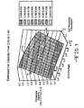
- Fig. 1 demonstrates application of equation 5 in determining deliverable capacity between any two-background voltage points.
- a Li/SVO/CF x cell having a theoretical capacity (B) of 2.5 Ah, as indicated by arrow 10 on the graph, and a SVO:CF x ratio of 1.1 (arrow 12).
- the C and D constants are 0.321 and 0.138, respectively. Curves 10 and 12 intersect at point 14 on the graph.
- the cell's discharge capacity (A) from ERI to EOL is determined to be about .58 Ah. This corresponds with the graph by reading over to the ordinate from point 14 to find that the deliverable capacity from ERI to EOL is about .58 Ah, as indioated by arrow 16.
- Figs. 2 and 3 show a patient P having a medical device 20, such as an implantable cardiac defibrillator, implanted inside the body.
- a medical device 20 such as an implantable cardiac defibrillator, implanted inside the body.
- An enlarged schematic of the medical device 20 is shown in Fig. 3 comprising a housing 22 containing control circuitry 24 powered by an electrochemical cell 26 of the present invention.
- the control circuitry 24 is connected to at least one conductor 28 by a hermetic feedthrough 30, as is well known by those skilled in the art.
- the distal end of the conductor connects to the heart H for delivering a therapy thereto.
- the patient will go to a medical facility, and the like, where the deliverable capacity determined by the control circuitry 24 is read to determine if the cell has discharged to the point that it is between the ERI and EOL voltages. If so, this indicates that it is time for the physician to schedule the patient for surgery to replace the medical device with a new one.
- SVO and CF x active materials reach end of life at the same time. This is the case in spite of the varied usage in actual implantable medical device application. Since both electrode materials reach end of service life at the same time, no energy capacity is wasted.
Landscapes
- Chemical & Material Sciences (AREA)
- Chemical Kinetics & Catalysis (AREA)
- Electrochemistry (AREA)
- General Chemical & Material Sciences (AREA)
- Engineering & Computer Science (AREA)
- Inorganic Chemistry (AREA)
- Materials Engineering (AREA)
- Health & Medical Sciences (AREA)
- Heart & Thoracic Surgery (AREA)
- Life Sciences & Earth Sciences (AREA)
- Cardiology (AREA)
- Veterinary Medicine (AREA)
- Manufacturing & Machinery (AREA)
- Biomedical Technology (AREA)
- Nuclear Medicine, Radiotherapy & Molecular Imaging (AREA)
- Radiology & Medical Imaging (AREA)
- Animal Behavior & Ethology (AREA)
- General Health & Medical Sciences (AREA)
- Public Health (AREA)
- Biophysics (AREA)
- Battery Electrode And Active Subsutance (AREA)
- Secondary Cells (AREA)
- Electrotherapy Devices (AREA)
- Primary Cells (AREA)
- Devices For Indicating Variable Information By Combining Individual Elements (AREA)
- External Artificial Organs (AREA)
- Cell Electrode Carriers And Collectors (AREA)
Claims (13)
- Implantierbare medizinische Vorrichtung, die folgendes aufweist:a) ein Gehäuseb) eine Steuerschaltung, die in dem Gehäuse untergebracht ist, um die Funktion der medizinischen Vorrichtung zu steuern;c) eine elektrochemische Zelle, die in dem Gehäuse untergebracht ist, um die Steuerschaltung mit Leistung zu versorgen, wobei die Zelle folgendes aufweist:i) eine Anode;ii) eine Kathode aus einem ersten kathodenaktiven Material, das sich von einem zweiten kathodenaktiven Material unterscheidet, wobei das erste kathodenaktive Material eine erste Energiedichte und einen ersten Nennstrom aufweist und das zweite kathodenaktive Material eine zweite Energiedichte und einen zweiten Nennstrom aufweist, wobei das erste kathodenaktive Material mit einer Seite eines Stromabnehmers kontaktiert ist und auf die Anode gerichtet ist, wobei das zweite kathodenaktive Material sich auf der gegenüber liegenden Seite des Stromabnehmers befindet, und wobei die erste Energiedichte des ersten kathodenaktiven Materials unter der Energiedichte des zweiten kathodenaktiven Materials liegt, während der erste Nennstrom des ersten kathodenaktiven Materials über dem zweiten Nennstrom des zweiten kathodenaktiven Materials liegt; undiii) einen Elektrolyten, der die Anode und die Kathode aktiviert; undd) einen Leiter zum Verbinden der medizinischen Vorrichtung mit einem Körper, der von der medizinischen Vorrichtung unterstützt werden soll;
dadurch gekennzeichnet, dasse) die verfügbare Kapazität der Zelle von der ERI-Spannung zur EOL-Spannung (A) von der Steuerschaltung mittels der Gleichung: A/B = [C x ein Verhältnis einer ersten theoretischen Kapazität des ersten kathodenaktiven Materials : einer zweiten theoretischen Kapazität des zweiten kathodenaktiven Materials + D] / (das Verhältnis der ersten theoretischen Kapazität : der zweiten theoretischen Kapazität + 1) bestimmt werden kann, wobei A die Entladungskapazität der Zelle von einer ERI (Elective Replacement Indicator)-Spannung zu einer EOL (End of Life)-Spannung ist und B die theoretische Kapazität der Zelle ist,
wobei C und D die Wirkungsgrade des ersten bzw. des zweiten kathodenaktiven Materials in Bezug auf die verfügbare Kapazität von der ERI-Spannung zur EOL-Spannung auf Prozentbasis der theoretischen Kapazität des Materials ist; undf) wobei die Steuerschaltung die verfügbare Kapazität der Zelle bestimmt, so dass die verfügbare Kapazität der Zelle ausgelesen werden kann, um zu bestimmen, ob die Zelle bis zu dem Punkt entladen wurde, dass sie zwischen ERI- und EOL-Spannung liegt. - Medizinische Vorrichtung nach Anspruch 1, wobei das zweite kathodenaktive Material ausgewählt ist aus der Gruppe, bestehend aus CFx, Ag2O, Ag2O2, CuF, Ag2CrO4, MnO2, SVO und deren Mischungen.
- Medizinische Vorrichtung nach Anspruch 1 oder Anspruch 2, wobei das erste kathodenaktive Material ausgewählt ist aus der Gruppe, bestehend aus SVO, CSVO, V2O5, MnO2, LiCoO2, LiNiO2, LiMnO2, LiMn2O4, CuO2, TiS2, Cu2S, FeS, FeS2, Kupferoxid, Kupfervanadiumoxid und deren Mischungen.
- Medizinische Vorrichtung nach Anspruch 1, wobei das erste kathodenaktive Material SVO ist und das zweite kathodenaktive Material CFx ist.
- Medizinische Vorrichtung nach Anspruch 4, wobei die ERI-Spannung etwa 2,65 Volt bis etwa 2,4 Volt ist.
- Medizinische Vorrichtung nach Anspruch 4 oder Anspruch 5, wobei die EOL-Spannung etwa 2,5 Volt bis etwa 2,0 Volt beträgt.
- Medizinische Vorrichtung nach einem der Ansprüche 4 bis 6, wobei das Kapazitätsverhältnis von SVO : CFx bei etwa 1 : 50 bis etwa 10 : 1 liegt.
- Medizinische Vorrichtung nach einem der Ansprüche 4 bis 7, wobei der Stromabnehmer ausgewählt ist aus der Gruppe bestehend aus Edelstahl, Titan, Tantal, Platin, Gold, Aluminium, Cobalt-Nickel-Legierungen, hochlegiertem ferritischem Edelstahl, der Molybdän und Chrom enthält, und nickel-, chrom- und molybdänhaltigen Legierungen.
- Medizinische Vorrichtung nach einem der Ansprüche 4 bis 8, einschließlich der Ausstattung mit einem Stromabnehmer aus Titan, der mit einer Beschichtung versehen ist, die ausgewählt ist aus der Gruppe bestehend aus Graphit/Kohlenstoff-Material, Gold, Iridium, Palladium, Platin, Rhodium, Ruthenium und deren Mischungen.
- Medizinische Vorrichtung nach einem der Ansprüche 4 bis 9, wobei die Kathode folgendermaßen aufgebaut ist: SVO / erster Stromabnehmer / CFx / zweiter Stromabnehmer / SVO.
- Medizinische Vorrichtung nach einem der Ansprüche 4 bis 9, wobei die Kathode folgendermaßen aufgebaut ist: SVO / erster Stromabnehmer / SVO / CFx / SVO/zweiter Stromabnehmer / SVO.
- Medizinische Vorrichtung nach einem der Ansprüche 4 bis 9, wobei Anode aus Lithium besteht und die Kathode folgendermaßen aufgebaut ist: SVO / Stromabnehmer / CFx, wobei das SVO auf die Lithiumanode gerichtet ist.
- Medizinische Vorrichtung nach einem der Ansprüche 4 bis 9, wobei die Anode aus Lithium besteht und die Kathode folgendermaßen aufgebaut ist: SVO / Stromabnehmer / SVO / CFx, wobei das SVO auf die Lithiumanode gerichtet ist.
Applications Claiming Priority (2)
| Application Number | Priority Date | Filing Date | Title |
|---|---|---|---|
| US34503101P | 2001-11-09 | 2001-11-09 | |
| US345031P | 2001-11-09 |
Publications (3)
| Publication Number | Publication Date |
|---|---|
| EP1310271A2 EP1310271A2 (de) | 2003-05-14 |
| EP1310271A3 EP1310271A3 (de) | 2004-06-23 |
| EP1310271B1 true EP1310271B1 (de) | 2007-08-15 |
Family
ID=23353168
Family Applications (1)
| Application Number | Title | Priority Date | Filing Date |
|---|---|---|---|
| EP02257777A Expired - Lifetime EP1310271B1 (de) | 2001-11-09 | 2002-11-11 | Elektrodenanordnung für Verwendungen einer implantierbaren Vorrichtung, die den electiven Ersetzungsindikator (ERI) benötigen |
Country Status (6)
| Country | Link |
|---|---|
| US (1) | US6936379B2 (de) |
| EP (1) | EP1310271B1 (de) |
| JP (1) | JP2004033723A (de) |
| AT (1) | ATE369892T1 (de) |
| CA (1) | CA2411678A1 (de) |
| DE (1) | DE60221771T2 (de) |
Families Citing this family (16)
| Publication number | Priority date | Publication date | Assignee | Title |
|---|---|---|---|---|
| US6849360B2 (en) | 2002-06-05 | 2005-02-01 | Eveready Battery Company, Inc. | Nonaqueous electrochemical cell with improved energy density |
| US10252062B2 (en) * | 2003-02-15 | 2019-04-09 | Medtronic, Inc. | Replacement indicator timer for implantable medical devices |
| US7776470B2 (en) | 2005-09-28 | 2010-08-17 | Greatbatch Ltd. | Anode-to-cathode capacity ratios for SVO/CF x hybrid cathode electrochemical cells |
| WO2007040547A1 (en) * | 2005-10-05 | 2007-04-12 | California Institute Of Technology | Subfluorinated graphite fluorides as electrode materials |
| US7646170B2 (en) * | 2006-05-11 | 2010-01-12 | Greatbatch Ltd. | Method of selecting replacement indicating voltage for an implantable electrochemical cell |
| US20070281213A1 (en) * | 2006-06-02 | 2007-12-06 | Gentcorp Ltd. | Carbon Monofluoride Cathode Materials Providing Simplified Elective Replacement Indication |
| US8192867B2 (en) | 2006-10-03 | 2012-06-05 | Greatbatch Ltd. | Hybrid cathode design for an electrochemical cell |
| US8364276B2 (en) | 2008-03-25 | 2013-01-29 | Ebr Systems, Inc. | Operation and estimation of output voltage of wireless stimulators |
| US8588926B2 (en) | 2008-03-25 | 2013-11-19 | Ebr Systems, Inc. | Implantable wireless accoustic stimulators with high energy conversion efficiencies |
| JP5599810B2 (ja) * | 2008-11-07 | 2014-10-01 | イーグルピッチャー テクノロジーズ,エルエルシー | 非結晶性または半結晶性の銅−マンガンの酸化物カソード材料である非水性セル |
| US8663825B2 (en) * | 2009-03-05 | 2014-03-04 | Eaglepicher Technologies, Llc | End of life indication system and method for non-aqueous cell having amorphous or semi-crystalline copper manganese oxide cathode material |
| JP5528534B2 (ja) * | 2009-03-18 | 2014-06-25 | イーグルピッチャー テクノロジーズ,エルエルシー | 少なくとも3種のカソード材料の混合物を有する非水電気化学セル |
| JP5599866B2 (ja) * | 2009-04-06 | 2014-10-01 | イーグルピッチャー テクノロジーズ,エルエルシー | 熱電池のカソード材料およびそれを含有する電池 |
| WO2010117954A1 (en) * | 2009-04-06 | 2010-10-14 | Eaglepicher Technologies, Llc | Thermal battery electrolyte compositions, electrode-electrolyte composites, and batteries including the same |
| US8652674B2 (en) | 2010-06-24 | 2014-02-18 | Eaglepicher Technologies, Llc | Thermal battery cathode materials containing nickel disulfide and batteries including same |
| US11654287B2 (en) | 2019-08-30 | 2023-05-23 | Ebr Systems, Inc. | Pulse delivery device including slew rate detector, and associated systems and methods |
Family Cites Families (3)
| Publication number | Priority date | Publication date | Assignee | Title |
|---|---|---|---|---|
| US5370668A (en) | 1993-06-22 | 1994-12-06 | Medtronic, Inc. | Fault-tolerant elective replacement indication for implantable medical device |
| US5569553A (en) * | 1995-03-08 | 1996-10-29 | Wilson Greatbatch Ltd. | Battery design for achieving end-of-life indication during electrical discharge |
| US6551747B1 (en) | 2000-04-27 | 2003-04-22 | Wilson Greatbatch Ltd. | Sandwich cathode design for alkali metal electrochemical cell with high discharge rate capability |
-
2002
- 2002-11-08 US US10/290,858 patent/US6936379B2/en not_active Expired - Lifetime
- 2002-11-11 JP JP2002364439A patent/JP2004033723A/ja active Pending
- 2002-11-11 AT AT02257777T patent/ATE369892T1/de not_active IP Right Cessation
- 2002-11-11 EP EP02257777A patent/EP1310271B1/de not_active Expired - Lifetime
- 2002-11-11 DE DE60221771T patent/DE60221771T2/de not_active Expired - Lifetime
- 2002-11-12 CA CA002411678A patent/CA2411678A1/en not_active Abandoned
Also Published As
| Publication number | Publication date |
|---|---|
| JP2004033723A (ja) | 2004-02-05 |
| CA2411678A1 (en) | 2003-05-09 |
| DE60221771T2 (de) | 2008-06-05 |
| EP1310271A3 (de) | 2004-06-23 |
| EP1310271A2 (de) | 2003-05-14 |
| DE60221771D1 (de) | 2007-09-27 |
| ATE369892T1 (de) | 2007-09-15 |
| US6936379B2 (en) | 2005-08-30 |
| US20030104269A1 (en) | 2003-06-05 |
Similar Documents
| Publication | Publication Date | Title |
|---|---|---|
| US6551747B1 (en) | Sandwich cathode design for alkali metal electrochemical cell with high discharge rate capability | |
| US6171729B1 (en) | Control of swelling in alkali metal electrochemical cells | |
| US7018743B2 (en) | Dual chemistry electrode design | |
| US6692871B2 (en) | Double current collector cathode design for alkali metal electrochemical cells having short circuit safety characteristics | |
| US7211349B2 (en) | Silver vanadium oxide provided with a metal oxide coating | |
| US6511772B2 (en) | Electrochemical cell having an electrode with a phosphate additive in the electrode active mixture | |
| US6692865B2 (en) | Double current collector cathode design using mixtures of two active materials for alkali metal or ion electrochemical cells | |
| EP1156544A2 (de) | Effiziente Zellenstapel für Zellen mit Doppelkollektor-Sandwich-Kathoden | |
| EP1014460A1 (de) | Glühen von Elektroden mit Metalloxidmischungen zur Verminderung von Polarisationswiderstand | |
| EP1331683A2 (de) | Aktives Kathodenmaterial beschichtet mit einem Metalloxid zum Einbau in eine elektrochemische Lithiumzelle | |
| US6926991B2 (en) | SVO/CFx parallel cell design within the same casing | |
| EP1310271B1 (de) | Elektrodenanordnung für Verwendungen einer implantierbaren Vorrichtung, die den electiven Ersetzungsindikator (ERI) benötigen | |
| EP1143544A2 (de) | Verwendung von Gamma-SVO und Mischung von Gamma-SVO / Epsilon-SVO in hochleistungsfähige elektrochemische Lithium-Zelle mit SVO/CFx/SVO Sandwich-Kathode | |
| US7776470B2 (en) | Anode-to-cathode capacity ratios for SVO/CF x hybrid cathode electrochemical cells | |
| JP2002270162A (ja) | 二種の活物質の混合物を用いた二重集電体カソード構造を含むアルカリ金属電池又はイオン電気化学的電池からなる電気化学セル | |
| US20030134188A1 (en) | Sandwich electrode design having relatively thin current collectors | |
| US8192867B2 (en) | Hybrid cathode design for an electrochemical cell | |
| US6673487B2 (en) | Double current collector cathode design using the same active material in varying thicknesses for alkali metal or ION electrochemical cells | |
| EP1914823B1 (de) | Hybridkathodenentwurf für eine elektrochemische Zelle | |
| EP1768203B1 (de) | Batterieelektroden | |
| US7056358B2 (en) | Method for using high rate lithium electrochemical cell containing SVO/CFchi/SVo sandwich cathodes having γ-SVO and mixture of γ-SVO/ε-SVO |
Legal Events
| Date | Code | Title | Description |
|---|---|---|---|
| PUAI | Public reference made under article 153(3) epc to a published international application that has entered the european phase |
Free format text: ORIGINAL CODE: 0009012 |
|
| AK | Designated contracting states |
Designated state(s): AT BE BG CH CY CZ DE DK EE ES FI FR GB GR IE IT LI LU MC NL PT SE SK TR |
|
| AX | Request for extension of the european patent |
Extension state: AL LT LV MK RO SI |
|
| PUAL | Search report despatched |
Free format text: ORIGINAL CODE: 0009013 |
|
| AK | Designated contracting states |
Kind code of ref document: A3 Designated state(s): AT BE BG CH CY CZ DE DK EE ES FI FR GB GR IE IT LI LU MC NL PT SE SK TR |
|
| AX | Request for extension of the european patent |
Extension state: AL LT LV MK RO SI |
|
| 17P | Request for examination filed |
Effective date: 20041216 |
|
| AKX | Designation fees paid |
Designated state(s): AT BE BG CH CY CZ DE DK EE ES FI FR GB GR IE IT LI LU MC NL PT SE SK TR |
|
| 17Q | First examination report despatched |
Effective date: 20050426 |
|
| GRAP | Despatch of communication of intention to grant a patent |
Free format text: ORIGINAL CODE: EPIDOSNIGR1 |
|
| RTI1 | Title (correction) |
Free format text: ELECTRODE DESIGN FOR IMPLANTABLE DEVICE APPLICATIONS THAT REQUIRE THE ELECTIVE REPLACEMENT INDICATOR (ERI) |
|
| RAP1 | Party data changed (applicant data changed or rights of an application transferred) |
Owner name: WILSON GREATBATCH TECHNOLOGIES, INC. |
|
| GRAS | Grant fee paid |
Free format text: ORIGINAL CODE: EPIDOSNIGR3 |
|
| GRAA | (expected) grant |
Free format text: ORIGINAL CODE: 0009210 |
|
| AK | Designated contracting states |
Kind code of ref document: B1 Designated state(s): AT BE BG CH CY CZ DE DK EE ES FI FR GB GR IE IT LI LU MC NL PT SE SK TR |
|
| REG | Reference to a national code |
Ref country code: GB Ref legal event code: FG4D |
|
| REG | Reference to a national code |
Ref country code: CH Ref legal event code: EP |
|
| REG | Reference to a national code |
Ref country code: IE Ref legal event code: FG4D |
|
| REF | Corresponds to: |
Ref document number: 60221771 Country of ref document: DE Date of ref document: 20070927 Kind code of ref document: P |
|
| REG | Reference to a national code |
Ref country code: SE Ref legal event code: TRGR |
|
| PG25 | Lapsed in a contracting state [announced via postgrant information from national office to epo] |
Ref country code: ES Free format text: LAPSE BECAUSE OF FAILURE TO SUBMIT A TRANSLATION OF THE DESCRIPTION OR TO PAY THE FEE WITHIN THE PRESCRIBED TIME-LIMIT Effective date: 20071126 Ref country code: BG Free format text: LAPSE BECAUSE OF FAILURE TO SUBMIT A TRANSLATION OF THE DESCRIPTION OR TO PAY THE FEE WITHIN THE PRESCRIBED TIME-LIMIT Effective date: 20071115 Ref country code: NL Free format text: LAPSE BECAUSE OF FAILURE TO SUBMIT A TRANSLATION OF THE DESCRIPTION OR TO PAY THE FEE WITHIN THE PRESCRIBED TIME-LIMIT Effective date: 20070815 Ref country code: FI Free format text: LAPSE BECAUSE OF FAILURE TO SUBMIT A TRANSLATION OF THE DESCRIPTION OR TO PAY THE FEE WITHIN THE PRESCRIBED TIME-LIMIT Effective date: 20070815 |
|
| NLV1 | Nl: lapsed or annulled due to failure to fulfill the requirements of art. 29p and 29m of the patents act | ||
| PG25 | Lapsed in a contracting state [announced via postgrant information from national office to epo] |
Ref country code: CH Free format text: LAPSE BECAUSE OF FAILURE TO SUBMIT A TRANSLATION OF THE DESCRIPTION OR TO PAY THE FEE WITHIN THE PRESCRIBED TIME-LIMIT Effective date: 20070815 Ref country code: AT Free format text: LAPSE BECAUSE OF FAILURE TO SUBMIT A TRANSLATION OF THE DESCRIPTION OR TO PAY THE FEE WITHIN THE PRESCRIBED TIME-LIMIT Effective date: 20070815 Ref country code: LI Free format text: LAPSE BECAUSE OF FAILURE TO SUBMIT A TRANSLATION OF THE DESCRIPTION OR TO PAY THE FEE WITHIN THE PRESCRIBED TIME-LIMIT Effective date: 20070815 |
|
| REG | Reference to a national code |
Ref country code: CH Ref legal event code: PL |
|
| ET | Fr: translation filed | ||
| PG25 | Lapsed in a contracting state [announced via postgrant information from national office to epo] |
Ref country code: BE Free format text: LAPSE BECAUSE OF FAILURE TO SUBMIT A TRANSLATION OF THE DESCRIPTION OR TO PAY THE FEE WITHIN THE PRESCRIBED TIME-LIMIT Effective date: 20070815 |
|
| PG25 | Lapsed in a contracting state [announced via postgrant information from national office to epo] |
Ref country code: GR Free format text: LAPSE BECAUSE OF FAILURE TO SUBMIT A TRANSLATION OF THE DESCRIPTION OR TO PAY THE FEE WITHIN THE PRESCRIBED TIME-LIMIT Effective date: 20071116 Ref country code: DK Free format text: LAPSE BECAUSE OF FAILURE TO SUBMIT A TRANSLATION OF THE DESCRIPTION OR TO PAY THE FEE WITHIN THE PRESCRIBED TIME-LIMIT Effective date: 20070815 |
|
| PG25 | Lapsed in a contracting state [announced via postgrant information from national office to epo] |
Ref country code: SK Free format text: LAPSE BECAUSE OF FAILURE TO SUBMIT A TRANSLATION OF THE DESCRIPTION OR TO PAY THE FEE WITHIN THE PRESCRIBED TIME-LIMIT Effective date: 20070815 Ref country code: PT Free format text: LAPSE BECAUSE OF FAILURE TO SUBMIT A TRANSLATION OF THE DESCRIPTION OR TO PAY THE FEE WITHIN THE PRESCRIBED TIME-LIMIT Effective date: 20080115 Ref country code: CZ Free format text: LAPSE BECAUSE OF FAILURE TO SUBMIT A TRANSLATION OF THE DESCRIPTION OR TO PAY THE FEE WITHIN THE PRESCRIBED TIME-LIMIT Effective date: 20070815 |
|
| PLBE | No opposition filed within time limit |
Free format text: ORIGINAL CODE: 0009261 |
|
| STAA | Information on the status of an ep patent application or granted ep patent |
Free format text: STATUS: NO OPPOSITION FILED WITHIN TIME LIMIT |
|
| PG25 | Lapsed in a contracting state [announced via postgrant information from national office to epo] |
Ref country code: MC Free format text: LAPSE BECAUSE OF NON-PAYMENT OF DUE FEES Effective date: 20071130 |
|
| 26N | No opposition filed |
Effective date: 20080516 |
|
| GBPC | Gb: european patent ceased through non-payment of renewal fee |
Effective date: 20071115 |
|
| PG25 | Lapsed in a contracting state [announced via postgrant information from national office to epo] |
Ref country code: IE Free format text: LAPSE BECAUSE OF NON-PAYMENT OF DUE FEES Effective date: 20071112 |
|
| PG25 | Lapsed in a contracting state [announced via postgrant information from national office to epo] |
Ref country code: GB Free format text: LAPSE BECAUSE OF NON-PAYMENT OF DUE FEES Effective date: 20071115 |
|
| PG25 | Lapsed in a contracting state [announced via postgrant information from national office to epo] |
Ref country code: EE Free format text: LAPSE BECAUSE OF FAILURE TO SUBMIT A TRANSLATION OF THE DESCRIPTION OR TO PAY THE FEE WITHIN THE PRESCRIBED TIME-LIMIT Effective date: 20070815 |
|
| PG25 | Lapsed in a contracting state [announced via postgrant information from national office to epo] |
Ref country code: CY Free format text: LAPSE BECAUSE OF FAILURE TO SUBMIT A TRANSLATION OF THE DESCRIPTION OR TO PAY THE FEE WITHIN THE PRESCRIBED TIME-LIMIT Effective date: 20070815 |
|
| REG | Reference to a national code |
Ref country code: FR Ref legal event code: TP |
|
| PG25 | Lapsed in a contracting state [announced via postgrant information from national office to epo] |
Ref country code: LU Free format text: LAPSE BECAUSE OF NON-PAYMENT OF DUE FEES Effective date: 20071111 |
|
| PG25 | Lapsed in a contracting state [announced via postgrant information from national office to epo] |
Ref country code: TR Free format text: LAPSE BECAUSE OF FAILURE TO SUBMIT A TRANSLATION OF THE DESCRIPTION OR TO PAY THE FEE WITHIN THE PRESCRIBED TIME-LIMIT Effective date: 20070815 |
|
| PG25 | Lapsed in a contracting state [announced via postgrant information from national office to epo] |
Ref country code: IT Free format text: LAPSE BECAUSE OF NON-PAYMENT OF DUE FEES Effective date: 20071130 |
|
| PGFP | Annual fee paid to national office [announced via postgrant information from national office to epo] |
Ref country code: FR Payment date: 20111128 Year of fee payment: 10 Ref country code: SE Payment date: 20111125 Year of fee payment: 10 |
|
| PG25 | Lapsed in a contracting state [announced via postgrant information from national office to epo] |
Ref country code: SE Free format text: LAPSE BECAUSE OF NON-PAYMENT OF DUE FEES Effective date: 20121112 |
|
| REG | Reference to a national code |
Ref country code: FR Ref legal event code: ST Effective date: 20130731 |
|
| PG25 | Lapsed in a contracting state [announced via postgrant information from national office to epo] |
Ref country code: FR Free format text: LAPSE BECAUSE OF NON-PAYMENT OF DUE FEES Effective date: 20121130 |
|
| PGFP | Annual fee paid to national office [announced via postgrant information from national office to epo] |
Ref country code: DE Payment date: 20211005 Year of fee payment: 20 |
|
| REG | Reference to a national code |
Ref country code: DE Ref legal event code: R071 Ref document number: 60221771 Country of ref document: DE |