EP1309820B1 - Automatic refill system for ultra pure or contamination sensitive chemicals - Google Patents
Automatic refill system for ultra pure or contamination sensitive chemicals Download PDFInfo
- Publication number
- EP1309820B1 EP1309820B1 EP01965845A EP01965845A EP1309820B1 EP 1309820 B1 EP1309820 B1 EP 1309820B1 EP 01965845 A EP01965845 A EP 01965845A EP 01965845 A EP01965845 A EP 01965845A EP 1309820 B1 EP1309820 B1 EP 1309820B1
- Authority
- EP
- European Patent Office
- Prior art keywords
- chemical
- refill system
- reservoir
- recited
- sensor
- Prior art date
- Legal status (The legal status is an assumption and is not a legal conclusion. Google has not performed a legal analysis and makes no representation as to the accuracy of the status listed.)
- Expired - Lifetime
Links
Images


Classifications
-
- F—MECHANICAL ENGINEERING; LIGHTING; HEATING; WEAPONS; BLASTING
- F17—STORING OR DISTRIBUTING GASES OR LIQUIDS
- F17C—VESSELS FOR CONTAINING OR STORING COMPRESSED, LIQUEFIED OR SOLIDIFIED GASES; FIXED-CAPACITY GAS-HOLDERS; FILLING VESSELS WITH, OR DISCHARGING FROM VESSELS, COMPRESSED, LIQUEFIED, OR SOLIDIFIED GASES
- F17C13/00—Details of vessels or of the filling or discharging of vessels
-
- F—MECHANICAL ENGINEERING; LIGHTING; HEATING; WEAPONS; BLASTING
- F17—STORING OR DISTRIBUTING GASES OR LIQUIDS
- F17C—VESSELS FOR CONTAINING OR STORING COMPRESSED, LIQUEFIED OR SOLIDIFIED GASES; FIXED-CAPACITY GAS-HOLDERS; FILLING VESSELS WITH, OR DISCHARGING FROM VESSELS, COMPRESSED, LIQUEFIED, OR SOLIDIFIED GASES
- F17C5/00—Methods or apparatus for filling containers with liquefied, solidified, or compressed gases under pressures
-
- F—MECHANICAL ENGINEERING; LIGHTING; HEATING; WEAPONS; BLASTING
- F17—STORING OR DISTRIBUTING GASES OR LIQUIDS
- F17C—VESSELS FOR CONTAINING OR STORING COMPRESSED, LIQUEFIED OR SOLIDIFIED GASES; FIXED-CAPACITY GAS-HOLDERS; FILLING VESSELS WITH, OR DISCHARGING FROM VESSELS, COMPRESSED, LIQUEFIED, OR SOLIDIFIED GASES
- F17C13/00—Details of vessels or of the filling or discharging of vessels
- F17C13/02—Special adaptations of indicating, measuring, or monitoring equipment
- F17C13/025—Special adaptations of indicating, measuring, or monitoring equipment having the pressure as the parameter
-
- F—MECHANICAL ENGINEERING; LIGHTING; HEATING; WEAPONS; BLASTING
- F17—STORING OR DISTRIBUTING GASES OR LIQUIDS
- F17C—VESSELS FOR CONTAINING OR STORING COMPRESSED, LIQUEFIED OR SOLIDIFIED GASES; FIXED-CAPACITY GAS-HOLDERS; FILLING VESSELS WITH, OR DISCHARGING FROM VESSELS, COMPRESSED, LIQUEFIED, OR SOLIDIFIED GASES
- F17C13/00—Details of vessels or of the filling or discharging of vessels
- F17C13/02—Special adaptations of indicating, measuring, or monitoring equipment
- F17C13/026—Special adaptations of indicating, measuring, or monitoring equipment having the temperature as the parameter
-
- F—MECHANICAL ENGINEERING; LIGHTING; HEATING; WEAPONS; BLASTING
- F17—STORING OR DISTRIBUTING GASES OR LIQUIDS
- F17C—VESSELS FOR CONTAINING OR STORING COMPRESSED, LIQUEFIED OR SOLIDIFIED GASES; FIXED-CAPACITY GAS-HOLDERS; FILLING VESSELS WITH, OR DISCHARGING FROM VESSELS, COMPRESSED, LIQUEFIED, OR SOLIDIFIED GASES
- F17C13/00—Details of vessels or of the filling or discharging of vessels
- F17C13/02—Special adaptations of indicating, measuring, or monitoring equipment
- F17C13/028—Special adaptations of indicating, measuring, or monitoring equipment having the volume as the parameter
-
- F—MECHANICAL ENGINEERING; LIGHTING; HEATING; WEAPONS; BLASTING
- F17—STORING OR DISTRIBUTING GASES OR LIQUIDS
- F17C—VESSELS FOR CONTAINING OR STORING COMPRESSED, LIQUEFIED OR SOLIDIFIED GASES; FIXED-CAPACITY GAS-HOLDERS; FILLING VESSELS WITH, OR DISCHARGING FROM VESSELS, COMPRESSED, LIQUEFIED, OR SOLIDIFIED GASES
- F17C13/00—Details of vessels or of the filling or discharging of vessels
- F17C13/04—Arrangement or mounting of valves
- F17C13/045—Automatic change-over switching assembly for bottled gas systems with two (or more) gas containers
-
- F—MECHANICAL ENGINEERING; LIGHTING; HEATING; WEAPONS; BLASTING
- F17—STORING OR DISTRIBUTING GASES OR LIQUIDS
- F17C—VESSELS FOR CONTAINING OR STORING COMPRESSED, LIQUEFIED OR SOLIDIFIED GASES; FIXED-CAPACITY GAS-HOLDERS; FILLING VESSELS WITH, OR DISCHARGING FROM VESSELS, COMPRESSED, LIQUEFIED, OR SOLIDIFIED GASES
- F17C5/00—Methods or apparatus for filling containers with liquefied, solidified, or compressed gases under pressures
- F17C5/002—Automated filling apparatus
- F17C5/005—Automated filling apparatus for gas bottles, such as on a continuous belt or on a merry-go-round
-
- G—PHYSICS
- G01—MEASURING; TESTING
- G01F—MEASURING VOLUME, VOLUME FLOW, MASS FLOW OR LIQUID LEVEL; METERING BY VOLUME
- G01F1/00—Measuring the volume flow or mass flow of fluid or fluent solid material wherein the fluid passes through a meter in a continuous flow
- G01F1/66—Measuring the volume flow or mass flow of fluid or fluent solid material wherein the fluid passes through a meter in a continuous flow by measuring frequency, phase shift or propagation time of electromagnetic or other waves, e.g. using ultrasonic flowmeters
- G01F1/667—Arrangements of transducers for ultrasonic flowmeters; Circuits for operating ultrasonic flowmeters
-
- G—PHYSICS
- G01—MEASURING; TESTING
- G01F—MEASURING VOLUME, VOLUME FLOW, MASS FLOW OR LIQUID LEVEL; METERING BY VOLUME
- G01F15/00—Details of, or accessories for, apparatus of groups G01F1/00 - G01F13/00 insofar as such details or appliances are not adapted to particular types of such apparatus
- G01F15/18—Supports or connecting means for meters
-
- G—PHYSICS
- G01—MEASURING; TESTING
- G01F—MEASURING VOLUME, VOLUME FLOW, MASS FLOW OR LIQUID LEVEL; METERING BY VOLUME
- G01F23/00—Indicating or measuring liquid level or level of fluent solid material, e.g. indicating in terms of volume or indicating by means of an alarm
- G01F23/22—Indicating or measuring liquid level or level of fluent solid material, e.g. indicating in terms of volume or indicating by means of an alarm by measuring physical variables, other than linear dimensions, pressure or weight, dependent on the level to be measured, e.g. by difference of heat transfer of steam or water
- G01F23/28—Indicating or measuring liquid level or level of fluent solid material, e.g. indicating in terms of volume or indicating by means of an alarm by measuring physical variables, other than linear dimensions, pressure or weight, dependent on the level to be measured, e.g. by difference of heat transfer of steam or water by measuring the variations of parameters of electromagnetic or acoustic waves applied directly to the liquid or fluent solid material
- G01F23/284—Electromagnetic waves
- G01F23/292—Light, e.g. infrared or ultraviolet
- G01F23/2921—Light, e.g. infrared or ultraviolet for discrete levels
-
- G—PHYSICS
- G01—MEASURING; TESTING
- G01F—MEASURING VOLUME, VOLUME FLOW, MASS FLOW OR LIQUID LEVEL; METERING BY VOLUME
- G01F23/00—Indicating or measuring liquid level or level of fluent solid material, e.g. indicating in terms of volume or indicating by means of an alarm
- G01F23/22—Indicating or measuring liquid level or level of fluent solid material, e.g. indicating in terms of volume or indicating by means of an alarm by measuring physical variables, other than linear dimensions, pressure or weight, dependent on the level to be measured, e.g. by difference of heat transfer of steam or water
- G01F23/28—Indicating or measuring liquid level or level of fluent solid material, e.g. indicating in terms of volume or indicating by means of an alarm by measuring physical variables, other than linear dimensions, pressure or weight, dependent on the level to be measured, e.g. by difference of heat transfer of steam or water by measuring the variations of parameters of electromagnetic or acoustic waves applied directly to the liquid or fluent solid material
- G01F23/284—Electromagnetic waves
- G01F23/292—Light, e.g. infrared or ultraviolet
- G01F23/2921—Light, e.g. infrared or ultraviolet for discrete levels
- G01F23/2922—Light, e.g. infrared or ultraviolet for discrete levels with light-conducting sensing elements, e.g. prisms
- G01F23/2925—Light, e.g. infrared or ultraviolet for discrete levels with light-conducting sensing elements, e.g. prisms using electrical detecting means
- G01F23/2927—Light, e.g. infrared or ultraviolet for discrete levels with light-conducting sensing elements, e.g. prisms using electrical detecting means for several discrete levels, e.g. with more than one light-conducting sensing element
-
- F—MECHANICAL ENGINEERING; LIGHTING; HEATING; WEAPONS; BLASTING
- F17—STORING OR DISTRIBUTING GASES OR LIQUIDS
- F17C—VESSELS FOR CONTAINING OR STORING COMPRESSED, LIQUEFIED OR SOLIDIFIED GASES; FIXED-CAPACITY GAS-HOLDERS; FILLING VESSELS WITH, OR DISCHARGING FROM VESSELS, COMPRESSED, LIQUEFIED, OR SOLIDIFIED GASES
- F17C2205/00—Vessel construction, in particular mounting arrangements, attachments or identifications means
- F17C2205/01—Mounting arrangements
- F17C2205/0123—Mounting arrangements characterised by number of vessels
- F17C2205/013—Two or more vessels
- F17C2205/0134—Two or more vessels characterised by the presence of fluid connection between vessels
- F17C2205/0146—Two or more vessels characterised by the presence of fluid connection between vessels with details of the manifold
-
- F—MECHANICAL ENGINEERING; LIGHTING; HEATING; WEAPONS; BLASTING
- F17—STORING OR DISTRIBUTING GASES OR LIQUIDS
- F17C—VESSELS FOR CONTAINING OR STORING COMPRESSED, LIQUEFIED OR SOLIDIFIED GASES; FIXED-CAPACITY GAS-HOLDERS; FILLING VESSELS WITH, OR DISCHARGING FROM VESSELS, COMPRESSED, LIQUEFIED, OR SOLIDIFIED GASES
- F17C2205/00—Vessel construction, in particular mounting arrangements, attachments or identifications means
- F17C2205/03—Fluid connections, filters, valves, closure means or other attachments
- F17C2205/0302—Fittings, valves, filters, or components in connection with the gas storage device
- F17C2205/0323—Valves
- F17C2205/0326—Valves electrically actuated
-
- F—MECHANICAL ENGINEERING; LIGHTING; HEATING; WEAPONS; BLASTING
- F17—STORING OR DISTRIBUTING GASES OR LIQUIDS
- F17C—VESSELS FOR CONTAINING OR STORING COMPRESSED, LIQUEFIED OR SOLIDIFIED GASES; FIXED-CAPACITY GAS-HOLDERS; FILLING VESSELS WITH, OR DISCHARGING FROM VESSELS, COMPRESSED, LIQUEFIED, OR SOLIDIFIED GASES
- F17C2205/00—Vessel construction, in particular mounting arrangements, attachments or identifications means
- F17C2205/03—Fluid connections, filters, valves, closure means or other attachments
- F17C2205/0302—Fittings, valves, filters, or components in connection with the gas storage device
- F17C2205/0323—Valves
- F17C2205/0335—Check-valves or non-return valves
-
- F—MECHANICAL ENGINEERING; LIGHTING; HEATING; WEAPONS; BLASTING
- F17—STORING OR DISTRIBUTING GASES OR LIQUIDS
- F17C—VESSELS FOR CONTAINING OR STORING COMPRESSED, LIQUEFIED OR SOLIDIFIED GASES; FIXED-CAPACITY GAS-HOLDERS; FILLING VESSELS WITH, OR DISCHARGING FROM VESSELS, COMPRESSED, LIQUEFIED, OR SOLIDIFIED GASES
- F17C2205/00—Vessel construction, in particular mounting arrangements, attachments or identifications means
- F17C2205/03—Fluid connections, filters, valves, closure means or other attachments
- F17C2205/0302—Fittings, valves, filters, or components in connection with the gas storage device
- F17C2205/0352—Pipes
- F17C2205/0364—Pipes flexible or articulated, e.g. a hose
-
- F—MECHANICAL ENGINEERING; LIGHTING; HEATING; WEAPONS; BLASTING
- F17—STORING OR DISTRIBUTING GASES OR LIQUIDS
- F17C—VESSELS FOR CONTAINING OR STORING COMPRESSED, LIQUEFIED OR SOLIDIFIED GASES; FIXED-CAPACITY GAS-HOLDERS; FILLING VESSELS WITH, OR DISCHARGING FROM VESSELS, COMPRESSED, LIQUEFIED, OR SOLIDIFIED GASES
- F17C2221/00—Handled fluid, in particular type of fluid
- F17C2221/01—Pure fluids
- F17C2221/014—Nitrogen
-
- F—MECHANICAL ENGINEERING; LIGHTING; HEATING; WEAPONS; BLASTING
- F17—STORING OR DISTRIBUTING GASES OR LIQUIDS
- F17C—VESSELS FOR CONTAINING OR STORING COMPRESSED, LIQUEFIED OR SOLIDIFIED GASES; FIXED-CAPACITY GAS-HOLDERS; FILLING VESSELS WITH, OR DISCHARGING FROM VESSELS, COMPRESSED, LIQUEFIED, OR SOLIDIFIED GASES
- F17C2221/00—Handled fluid, in particular type of fluid
- F17C2221/05—Ultrapure fluid
-
- F—MECHANICAL ENGINEERING; LIGHTING; HEATING; WEAPONS; BLASTING
- F17—STORING OR DISTRIBUTING GASES OR LIQUIDS
- F17C—VESSELS FOR CONTAINING OR STORING COMPRESSED, LIQUEFIED OR SOLIDIFIED GASES; FIXED-CAPACITY GAS-HOLDERS; FILLING VESSELS WITH, OR DISCHARGING FROM VESSELS, COMPRESSED, LIQUEFIED, OR SOLIDIFIED GASES
- F17C2223/00—Handled fluid before transfer, i.e. state of fluid when stored in the vessel or before transfer from the vessel
- F17C2223/01—Handled fluid before transfer, i.e. state of fluid when stored in the vessel or before transfer from the vessel characterised by the phase
- F17C2223/0107—Single phase
- F17C2223/0123—Single phase gaseous, e.g. CNG, GNC
-
- F—MECHANICAL ENGINEERING; LIGHTING; HEATING; WEAPONS; BLASTING
- F17—STORING OR DISTRIBUTING GASES OR LIQUIDS
- F17C—VESSELS FOR CONTAINING OR STORING COMPRESSED, LIQUEFIED OR SOLIDIFIED GASES; FIXED-CAPACITY GAS-HOLDERS; FILLING VESSELS WITH, OR DISCHARGING FROM VESSELS, COMPRESSED, LIQUEFIED, OR SOLIDIFIED GASES
- F17C2223/00—Handled fluid before transfer, i.e. state of fluid when stored in the vessel or before transfer from the vessel
- F17C2223/01—Handled fluid before transfer, i.e. state of fluid when stored in the vessel or before transfer from the vessel characterised by the phase
- F17C2223/0107—Single phase
- F17C2223/013—Single phase liquid
-
- F—MECHANICAL ENGINEERING; LIGHTING; HEATING; WEAPONS; BLASTING
- F17—STORING OR DISTRIBUTING GASES OR LIQUIDS
- F17C—VESSELS FOR CONTAINING OR STORING COMPRESSED, LIQUEFIED OR SOLIDIFIED GASES; FIXED-CAPACITY GAS-HOLDERS; FILLING VESSELS WITH, OR DISCHARGING FROM VESSELS, COMPRESSED, LIQUEFIED, OR SOLIDIFIED GASES
- F17C2225/00—Handled fluid after transfer, i.e. state of fluid after transfer from the vessel
- F17C2225/01—Handled fluid after transfer, i.e. state of fluid after transfer from the vessel characterised by the phase
- F17C2225/0107—Single phase
- F17C2225/0123—Single phase gaseous, e.g. CNG, GNC
-
- F—MECHANICAL ENGINEERING; LIGHTING; HEATING; WEAPONS; BLASTING
- F17—STORING OR DISTRIBUTING GASES OR LIQUIDS
- F17C—VESSELS FOR CONTAINING OR STORING COMPRESSED, LIQUEFIED OR SOLIDIFIED GASES; FIXED-CAPACITY GAS-HOLDERS; FILLING VESSELS WITH, OR DISCHARGING FROM VESSELS, COMPRESSED, LIQUEFIED, OR SOLIDIFIED GASES
- F17C2227/00—Transfer of fluids, i.e. method or means for transferring the fluid; Heat exchange with the fluid
- F17C2227/01—Propulsion of the fluid
- F17C2227/0114—Propulsion of the fluid with vacuum injectors, e.g. venturi
-
- F—MECHANICAL ENGINEERING; LIGHTING; HEATING; WEAPONS; BLASTING
- F17—STORING OR DISTRIBUTING GASES OR LIQUIDS
- F17C—VESSELS FOR CONTAINING OR STORING COMPRESSED, LIQUEFIED OR SOLIDIFIED GASES; FIXED-CAPACITY GAS-HOLDERS; FILLING VESSELS WITH, OR DISCHARGING FROM VESSELS, COMPRESSED, LIQUEFIED, OR SOLIDIFIED GASES
- F17C2227/00—Transfer of fluids, i.e. method or means for transferring the fluid; Heat exchange with the fluid
- F17C2227/04—Methods for emptying or filling
-
- F—MECHANICAL ENGINEERING; LIGHTING; HEATING; WEAPONS; BLASTING
- F17—STORING OR DISTRIBUTING GASES OR LIQUIDS
- F17C—VESSELS FOR CONTAINING OR STORING COMPRESSED, LIQUEFIED OR SOLIDIFIED GASES; FIXED-CAPACITY GAS-HOLDERS; FILLING VESSELS WITH, OR DISCHARGING FROM VESSELS, COMPRESSED, LIQUEFIED, OR SOLIDIFIED GASES
- F17C2227/00—Transfer of fluids, i.e. method or means for transferring the fluid; Heat exchange with the fluid
- F17C2227/04—Methods for emptying or filling
- F17C2227/044—Methods for emptying or filling by purging
-
- F—MECHANICAL ENGINEERING; LIGHTING; HEATING; WEAPONS; BLASTING
- F17—STORING OR DISTRIBUTING GASES OR LIQUIDS
- F17C—VESSELS FOR CONTAINING OR STORING COMPRESSED, LIQUEFIED OR SOLIDIFIED GASES; FIXED-CAPACITY GAS-HOLDERS; FILLING VESSELS WITH, OR DISCHARGING FROM VESSELS, COMPRESSED, LIQUEFIED, OR SOLIDIFIED GASES
- F17C2227/00—Transfer of fluids, i.e. method or means for transferring the fluid; Heat exchange with the fluid
- F17C2227/04—Methods for emptying or filling
- F17C2227/045—Methods for emptying or filling by vacuum
-
- F—MECHANICAL ENGINEERING; LIGHTING; HEATING; WEAPONS; BLASTING
- F17—STORING OR DISTRIBUTING GASES OR LIQUIDS
- F17C—VESSELS FOR CONTAINING OR STORING COMPRESSED, LIQUEFIED OR SOLIDIFIED GASES; FIXED-CAPACITY GAS-HOLDERS; FILLING VESSELS WITH, OR DISCHARGING FROM VESSELS, COMPRESSED, LIQUEFIED, OR SOLIDIFIED GASES
- F17C2250/00—Accessories; Control means; Indicating, measuring or monitoring of parameters
- F17C2250/03—Control means
- F17C2250/032—Control means using computers
-
- F—MECHANICAL ENGINEERING; LIGHTING; HEATING; WEAPONS; BLASTING
- F17—STORING OR DISTRIBUTING GASES OR LIQUIDS
- F17C—VESSELS FOR CONTAINING OR STORING COMPRESSED, LIQUEFIED OR SOLIDIFIED GASES; FIXED-CAPACITY GAS-HOLDERS; FILLING VESSELS WITH, OR DISCHARGING FROM VESSELS, COMPRESSED, LIQUEFIED, OR SOLIDIFIED GASES
- F17C2250/00—Accessories; Control means; Indicating, measuring or monitoring of parameters
- F17C2250/04—Indicating or measuring of parameters as input values
- F17C2250/0404—Parameters indicated or measured
- F17C2250/0408—Level of content in the vessel
- F17C2250/0413—Level of content in the vessel with floats
-
- F—MECHANICAL ENGINEERING; LIGHTING; HEATING; WEAPONS; BLASTING
- F17—STORING OR DISTRIBUTING GASES OR LIQUIDS
- F17C—VESSELS FOR CONTAINING OR STORING COMPRESSED, LIQUEFIED OR SOLIDIFIED GASES; FIXED-CAPACITY GAS-HOLDERS; FILLING VESSELS WITH, OR DISCHARGING FROM VESSELS, COMPRESSED, LIQUEFIED, OR SOLIDIFIED GASES
- F17C2250/00—Accessories; Control means; Indicating, measuring or monitoring of parameters
- F17C2250/04—Indicating or measuring of parameters as input values
- F17C2250/0404—Parameters indicated or measured
- F17C2250/0421—Mass or weight of the content of the vessel
-
- F—MECHANICAL ENGINEERING; LIGHTING; HEATING; WEAPONS; BLASTING
- F17—STORING OR DISTRIBUTING GASES OR LIQUIDS
- F17C—VESSELS FOR CONTAINING OR STORING COMPRESSED, LIQUEFIED OR SOLIDIFIED GASES; FIXED-CAPACITY GAS-HOLDERS; FILLING VESSELS WITH, OR DISCHARGING FROM VESSELS, COMPRESSED, LIQUEFIED, OR SOLIDIFIED GASES
- F17C2250/00—Accessories; Control means; Indicating, measuring or monitoring of parameters
- F17C2250/04—Indicating or measuring of parameters as input values
- F17C2250/0404—Parameters indicated or measured
- F17C2250/0426—Volume
-
- F—MECHANICAL ENGINEERING; LIGHTING; HEATING; WEAPONS; BLASTING
- F17—STORING OR DISTRIBUTING GASES OR LIQUIDS
- F17C—VESSELS FOR CONTAINING OR STORING COMPRESSED, LIQUEFIED OR SOLIDIFIED GASES; FIXED-CAPACITY GAS-HOLDERS; FILLING VESSELS WITH, OR DISCHARGING FROM VESSELS, COMPRESSED, LIQUEFIED, OR SOLIDIFIED GASES
- F17C2250/00—Accessories; Control means; Indicating, measuring or monitoring of parameters
- F17C2250/04—Indicating or measuring of parameters as input values
- F17C2250/0404—Parameters indicated or measured
- F17C2250/043—Pressure
-
- F—MECHANICAL ENGINEERING; LIGHTING; HEATING; WEAPONS; BLASTING
- F17—STORING OR DISTRIBUTING GASES OR LIQUIDS
- F17C—VESSELS FOR CONTAINING OR STORING COMPRESSED, LIQUEFIED OR SOLIDIFIED GASES; FIXED-CAPACITY GAS-HOLDERS; FILLING VESSELS WITH, OR DISCHARGING FROM VESSELS, COMPRESSED, LIQUEFIED, OR SOLIDIFIED GASES
- F17C2250/00—Accessories; Control means; Indicating, measuring or monitoring of parameters
- F17C2250/04—Indicating or measuring of parameters as input values
- F17C2250/0404—Parameters indicated or measured
- F17C2250/0439—Temperature
-
- F—MECHANICAL ENGINEERING; LIGHTING; HEATING; WEAPONS; BLASTING
- F17—STORING OR DISTRIBUTING GASES OR LIQUIDS
- F17C—VESSELS FOR CONTAINING OR STORING COMPRESSED, LIQUEFIED OR SOLIDIFIED GASES; FIXED-CAPACITY GAS-HOLDERS; FILLING VESSELS WITH, OR DISCHARGING FROM VESSELS, COMPRESSED, LIQUEFIED, OR SOLIDIFIED GASES
- F17C2250/00—Accessories; Control means; Indicating, measuring or monitoring of parameters
- F17C2250/04—Indicating or measuring of parameters as input values
- F17C2250/0404—Parameters indicated or measured
- F17C2250/0473—Time or time periods
-
- F—MECHANICAL ENGINEERING; LIGHTING; HEATING; WEAPONS; BLASTING
- F17—STORING OR DISTRIBUTING GASES OR LIQUIDS
- F17C—VESSELS FOR CONTAINING OR STORING COMPRESSED, LIQUEFIED OR SOLIDIFIED GASES; FIXED-CAPACITY GAS-HOLDERS; FILLING VESSELS WITH, OR DISCHARGING FROM VESSELS, COMPRESSED, LIQUEFIED, OR SOLIDIFIED GASES
- F17C2250/00—Accessories; Control means; Indicating, measuring or monitoring of parameters
- F17C2250/06—Controlling or regulating of parameters as output values
- F17C2250/0605—Parameters
- F17C2250/0636—Flow or movement of content
-
- F—MECHANICAL ENGINEERING; LIGHTING; HEATING; WEAPONS; BLASTING
- F17—STORING OR DISTRIBUTING GASES OR LIQUIDS
- F17C—VESSELS FOR CONTAINING OR STORING COMPRESSED, LIQUEFIED OR SOLIDIFIED GASES; FIXED-CAPACITY GAS-HOLDERS; FILLING VESSELS WITH, OR DISCHARGING FROM VESSELS, COMPRESSED, LIQUEFIED, OR SOLIDIFIED GASES
- F17C2250/00—Accessories; Control means; Indicating, measuring or monitoring of parameters
- F17C2250/07—Actions triggered by measured parameters
- F17C2250/072—Action when predefined value is reached
-
- F—MECHANICAL ENGINEERING; LIGHTING; HEATING; WEAPONS; BLASTING
- F17—STORING OR DISTRIBUTING GASES OR LIQUIDS
- F17C—VESSELS FOR CONTAINING OR STORING COMPRESSED, LIQUEFIED OR SOLIDIFIED GASES; FIXED-CAPACITY GAS-HOLDERS; FILLING VESSELS WITH, OR DISCHARGING FROM VESSELS, COMPRESSED, LIQUEFIED, OR SOLIDIFIED GASES
- F17C2270/00—Applications
- F17C2270/05—Applications for industrial use
- F17C2270/0518—Semiconductors
-
- Y—GENERAL TAGGING OF NEW TECHNOLOGICAL DEVELOPMENTS; GENERAL TAGGING OF CROSS-SECTIONAL TECHNOLOGIES SPANNING OVER SEVERAL SECTIONS OF THE IPC; TECHNICAL SUBJECTS COVERED BY FORMER USPC CROSS-REFERENCE ART COLLECTIONS [XRACs] AND DIGESTS
- Y10—TECHNICAL SUBJECTS COVERED BY FORMER USPC
- Y10T—TECHNICAL SUBJECTS COVERED BY FORMER US CLASSIFICATION
- Y10T137/00—Fluid handling
- Y10T137/2931—Diverse fluid containing pressure systems
- Y10T137/3115—Gas pressure storage over or displacement of liquid
- Y10T137/3127—With gas maintenance or application
Definitions
- the present invention relates to a system for supplying ultra pure and contamination sensitive chemicals to production lines for forming semiconductors, fiber optics, or like components. More particularly, this invention relates to a system carrying pyrophoric chemicals which allows the production line to operate continuously, and without interruption.
- Processing chemicals are liquids which may be directly injected into the processing stations, or which may be carried to the processing stations in a carrier gas. Direct chemical injection may be from bulk supply tanks, or may be from smaller supply containers which will be periodically refilled by bulk supply tanks. When the chemicals are applied by means of carrier gases, the liquid chemicals will be contained in temperature-controlled ampules or work cylinders, called "bubblers". A stream of an inert carrier gas, such as nitrogen, helium, or the like, is injected into the bubbler ampules.
- an inert carrier gas such as nitrogen, helium, or the like
- the inert carrier gas bubbles upwardly through the liquid chemical in the bubbler ampule and creates a chemical-saturated carrier gas atmosphere in the ampule in the space above the supply of liquid chemical contained therein.
- the chemically saturated carrier gas is continuously drawn out of the bubbler and transferred into the component processing station, such as a diffusion furnace, as noted above.
- the processing lines depend on a continuous supply of the chemicals being delivered from the chemical source in order to operate properly and efficiently. If the supply of the processing chemicals is interrupted, the production line must be shut down, and the diffusion furnace must be placed in a "idle" mode. If the chemical ampules are depleted of processing chemicals, they must be removed from the production line and replaced with freshly filled ampules.
- additional bulk chemical supply containers may be incorporated into the production line.
- a single bulk supply container When a single bulk supply container is used in the production line, it must be periodically refilled with processing chemicals. The line must be shut down while the bulk supply container is refilled. The line can be run for a longer time period due to the use of the bulk supply container, however, the line still must be periodically shut down when the bulk supply container is depleted.
- two bulk supply containers one is a fixed container and the other is a replaceable mobile container.
- the ampule is replenished with chemicals from the fixed bulk container, and the fixed bulk container is refilled with chemicals from the replaceable, or shuttle, bulk container.
- the fixed bulk container is typically positioned on a scale or connected to a load cell so that the volume of chemical in the fixed bulk container is continuously monitored. Signals are transmitted to the system microprocessor controller or "junction box" which are indicative of the volume of chemical remaining in the fixed bulk container.
- the microprocessor controller manages about 2 points of use. For each point of use, there are four level sensors, i.e., empty, low, high or overflow. The low or high corresponds to the "start" and "stop” sensors which trigger the signal initiation to fill the ampule or the removal of the request.
- the empty or overflow (“overfill”) sensors are emergency sensors if the start and stop sensors fail.
- the supply voltage for the sensor circuit is about +24 volts. All level sensors connect to +24 volt when dry.
- a pressure switch generates a junction box alarm when there is not enough clean dry air (CDA) pressure.
- the electrical connections include main power and interface connections. Power is configured for 110VAC or 230VAC.
- a circuit breaker located where the main power is connected can be used to shut off all power to the unit. Twin fans act to cool the electronics area of the unit.
- a dispense request connector is used to interface with the process equipment, in addition to supplying status and alarm signals.
- the controller activates a chemical transfer valve system which transfers chemical from the shuttle bulk container to the fixed bulk container, and when the fixed bulk container has been refilled, the controller deactivates the chemical transfer valve system.
- the fixed bulk supply container will be refilled several times before the shuttle supply container must be refilled.
- the shuttle bulk supply container has been substantially emptied, the shuttle container is removed from the production line and is refilled at an off-site chemical supply repository, which is typically far removed from the processing plant.
- the bubblers are held in liquid, temperature-controlled baths, and must be periodically replaced based on the usage of the ultra high purity pyrophoric metalorganic (PMO) source chemical.
- the amount of chemical used is a function of the degree of saturation of the hydrogen carrier gas carrying the PMO chemical to the metalorganic chemical vapor deposition (MOCVD) reactor and the quantity of carrier gas used.
- Typical carrier gases are nitrogen, argon, or helium, but the preferred gas for PMO CVD is ultra high purity hydrogen.
- Some typical chemicals utilized in bubblers are trimethylgallium (TMG), triethylgallium (TEG), trimethylaluminum (TMA) and dopant chemicals, such as dimethylzinc (DMZ) and diethylzinc (DEZ).
- test samples are next run through the process to ensure that the replenished chemical is not contaminated, and that it is otherwise acceptable for use in the process, prior to resuming the production operation.
- the total, liquid chemical replacement process can take from two to eight hours, depending upon the chemical involved and the end product being made by the MOCVD machine.
- This invention relates generally to a system to automatically refill a liquid from a bulk container to a smaller receiving container without contamination. More specifically, it relates to a modular system providing fresh liquid pyrophoric metalorganic (PMO) chemicals through an automatic refill to a plurality of working cylinders (in their corresponding temperature controlled baths) that supply a vapor to a corresponding number of metalorganic chemical vapor deposition (MOCVD) machines.
- PMO pyrophoric metalorganic
- MOCVD metalorganic chemical vapor deposition
- venturi for the present invention is not only unique, but often overlooked. This is due to the fact that under normal conditions, the vacuum that can be generated by the venturi is not sufficient to evaluate all of the pyrophoric chemicals so one could safely open the system for a container exchange. Thus, based on theoretical calculations, this type of a system would not work. However, the present inventors have incorporated the use of the venturi with a dilution/purge routine that surprisingly allows for all of the chemical to be removed from the system. Thus, a safe container exchange is possible. This avoids the conventional use of vacuum pumps or other such expensive equipment to achieve the desired vacuum.
- a further improvement beyond using a venturi vacuum source with PMO's is the addition of a valve at the exhaust of the venturi, a feature that is lacking in European Patent Application No. EP 0 723 214 A1, to Goossens et al .
- PMO's commonly decompose in the presence of oxygen or other contaminants to form an intractable, solid residue. Without this additional valve, it is possible for oxygen or other contaminants to diffuse down the exhaust line to the venturi and react with any PMO residues that might remain there. Repeated use of the venturi followed by such residue formation could eventually lead to reduced effectiveness or even blockage of the venturi. With the additional valve, such contamination is avoided and the venturi is kept free of residue. This extends the functional lifetime of the venturi, and lengthens the time between preventative maintenance cycles.
- the present invention is directed to a chemical refill system which comprises: (a) at least one first chemical reservoir; (b) at least one second chemical reservoir; (c) a means for supplying gas to the chemical refill system; (d) a conduit means for connecting the means for supplying gas, the first chemical reservoir, and the second chemical reservoir; (e) at least one venturi comprising a gas inlet, a gas outlet and an exhaust gas outlet, the venturi being disposed between the means for supplying gas and the first and second reservoirs; and (f) at least one valve disposed about the exhaust outlet, wherein the valve prevents diffusion of oxygen or any contaminants into the system.
- the first chemical reservoir is a bulk chemical supply tank and the second chemical reservoir is an ampule and receives chemical from said first chemical reservoir and delivers chemical to a means for applying the chemical.
- the conduit means connects the chemical refill system to a means for applying the chemical and comprises a plurality of transfer lines and a plurality of valves.
- One embodiment of the chemical refill system further comprises a volume sensor which is capable of monitoring the volume of chemicals remaining in the first and second chemical reservoir.
- the volume sensor is operable to monitor the volume of chemical in the first and second chemical reservoirs using one selected from the group consisting of: optical sensor, thermal conductance sensor, capacitance sensor, weight scale, sonic sensor, weight scale, and nitrogen back pressure sensor,
- the volume sensor is an optical sensor utilizing a glass rod encased in the first and second chemical reservoirs or a thermal conductance sensor utilizing a thermistor encased in the first and second chemical reservoirs.
- a further embodiment of the chemical refill system further comprises a liquid temperature sensor in each of the first and second chemical reservoirs.
- a further embodiment of the chemical refill system comprises a microprocessor controller means for selectively operating the chemical refill system.
- the microprocessor controller means is a programmable logic controller.
- the microprocessor controller means further comprises a set of solenoid valves.
- One embodiment of the chemical refill system comprises two of the first chemical reservoir and two of the second chemical reservoir.
- the chemical refill system for this embodiment has a microprocessor controller means which selectively operates the system in a fixed/shuttle mode which mode involves the use of a fixed first chemical reservoir and the use of a shuttle first chemical reservoir, or in a shuttle/shuttle mode which mode involves the use of a plurality of shuttle first chemical reservoirs.
- the present invention is also directed to a process for transporting a chemical: (a) using a chemical refill system further comprising a microprocessor controller means which comprises a plurality of independently operating microprocessor-controlled modules, each module being matched electrically to each first chemical reservoir, and programmed to control the refilling operation of said corresponding first chemical reservoir; (b) monitoring the volume of chemical within said corresponding first chemical reservoir; wherein each independently operating microprocessor-controlled module may be removed from the microprocessor controller without interrupting the operation of the remaining microprocessor-controlled modules and their corresponding first chemical reservoirs and wherein each microprocessor-controlled module; (c) sensing an alarm condition from a volume sensor; and (d) causing through the sensing of step (c) either a refill of that working reservoir or a shut down of that automatic refill line, and wherein all microprocessor-controlled modules, upon sensing a low level or low pressure alarm condition from said sensor in the first chemical reservoir will act synchronously to cease operation from that first chemical reservoir.
- a microprocessor controller means which
- Another embodiment of the invention further comprises at least two check valves, wherein the check valves control the conduit means between each of said first chemical reservoir.
- the chemical refill system transports pyrophoric chemicals.
- the chemical refill system transports liquid pyrophoric metalorganic chemicals.
- Fig. 1 is a schematic view of an ultra pure or contamination sensitive chemical dispensing system which forms a part of a production line for processing semiconductors, or the like.
- the left side of Fig. 1 shows the bulk chemical supply tanks and the valving and conduit scheme for the purge gas and chemical refill manifold.
- the bulk chemical supply tanks are denoted by the numerals 50 and 52.
- One or both of them can be shuttle tanks. When only one tank is a shuttle tank, the other will be a fixed tank which is not designed to be removed from the cabinet 48. In either case, the cabinet 48 will be provided with scales 54 and 56, one for each of the tanks 50 and 52.
- the cabinet assembly is thus capable of being used in a shuttle/shuttle mode, and is also capable of being used in a fixed/shuttle mode.
- the scales 54 and 56 monitor the amount of chemical which remains in each tank 50 and 52 at all times, and are operable to send appropriate signals to the controller so that the shuttle tank can be removed and replaced with a new shuttle tank in a manner which allows the production line to remain in continuous operation for an indeterminate time period.
- the manifold includes a plurality of outlet passages 60, 62, 64, and 66 which are connected to individual bubblers or ampules.
- the outlet passages arc each provided with individual control valves V1, V2, V3, and V4, respectively, which are actuated by the system controller so that the chemical from the tanks 50 and 52 may be selectively transferred to bubblers which require chemical replenishment.
- Transfer passages 68 and 70 are operable to transfer chemical from the tanks 50 and 52, respectively, to the outlet passages 60, 62, 64, and 66.
- Each of the transfer passages 68 and 70 is provided with respective valves V5 and V6 which are operable to control chemical flow from the tanks 50 and 52. Valves V5 and V6 are also actuated by the system controller.
- the chemical is forced out of tanks 50 and 52 by means of a tank-pressurizing gas source 55.
- Pressure gauges P1 and P2 are used to monitor the gas pressure in the tanks 50 and 52, respectively.
- the gas source is operable to selectively provide a pressurized stream of an inert dry gas, such as helium or nitrogen, to tanks 50 and 52 through passages 72 and 74.
- the flow of pressurizing gas to tanks 50 and 52 through passages 72 and 74 is controlled in part by valves DV3 and DV6; and the transfer of chemicals from tanks 50 and 52 to passages 68 and 70 is controlled in part by valves DV2 and DV7, respectively.
- Valves DV2, DV3, DV6 and DV7 are manually operated, and arc kept open during normal system operation.
- Valves DV1, DV4, DV5 and DV8 are leak test ports.
- a second source of pressurized gas is included in the system for use in applying a vacuum to the manifold assembly.
- the pressurized gas source opens into a line which is controlled by valve V15 and when valve V15 is open, the gas stream passes through venturi nozzle 78 so as to impose a vacuum in line 80 which opens into venturi nozzle 78.
- the venturi pulls vacuum on the manifold so that there is no need to connect the system to an external supply of vacuum.
- An additional valve V16 is located at the exit of the venturi. Valve V16 prevents back diffusion of oxygen or any moisture or air that may be detrimental to ultra pure or contamination sensitive chemicals.
- valves DV2 and DV3 are kept open during normal operation of the system.
- valves V1, V2, V3 or V4 will be opened along with valves V5 and V9.
- Valves CV1 and CV2 are check valves which prevent back flow of gas into the gas source. All of the remaining valves except for DV6 and DV7 will be closed.
- Opening valve V9 allows the pressurizing gas from the gas source to enter tank 50, pressurizing the latter sufficiently to force the chemicals up through tube 51 into line 68 and out through the opened outlet passages.
- the chemical is transferred to bubbler ampule 4 through a line 46 which connects with an extended tube 41 via a valve 45 which remains open at all times during normal operation of the system.
- the transferred chemicals enter ampule 4 through the open end of tube 41.
- the controller automatically closes valves V5 and V9 along with the opened outlet valve.
- scale 54 monitors the amount of chemicals remaining in tank 50, and when the chemical amount reaches a predetermined minimal amount, the controller will provide a signal to the system operator that the tank is to be removed from the cabinet when the system is a shuttle/shuttle system.
- scale 54 When the system is operating in a fixed/shuttle mode such that tank 50 is the fixed tank and tank 52 is the shuttle tank, scale 54 will signal the controller when the chemical level in tank 50 has reached a refill level, preferably about 75% of capacity, and the controller will open the correct valves in the system so as to effect a transfer of chemical from tank 52 to tank 50. Assuming at this point that all of the valves except DV2, DV3, DV6, and DV7 are closed, the controller will open valves V10, V5, and V6. This will cause the pressurized gas from the gas source to pressurize the tank 52 to the extent needed to force the chemical up through tube 71 into passage 70 and through the valves V5 and V6 to line 68.
- the microprocessor controller when operating the system in the shuttle/shuttle mode, periodically actuates the valves to open one of the second and third chemical transfer lines upon receipt of the need-to-add level of chemical signal from the level detectors and, after receipt of a tank-empty signal from one of the volume sensors, to periodically subsequently actuate the valves to open the other of the second and third chemical transfer lines upon receipt of subsequent need-to-add level of chemical signals from the level detectors, and to keep the valves in a condition which holds the first chemical transfer line in a closed condition.
- the empty tank to be replaced will be the shuttle tank in the fixed/shuttle mode, and alternating ones of the tanks in the shuttle/shuttle mode. Assuming that tank 52 is the tank to be replaced with a full tank, the controller will be signaled by scale 56 that tank 52 is empty, i.e., that the chemical level is below the lower end of tube 71.
- “Blowing out” refers to the removal of liquid in lines of the manifold when the latter are full of chemical. “Purging” refers to the removal of any residual liquid remaining in the lines after the “blowing out” operation. “Flushing” refers to the constant flow of gas through the lines to eliminate line contamination which connections are being made.
- valve V15 so as to direct a stream of compressed gas through venturi 78 and out through valve V16. This will draw a vacuum in the line 80 and in line 84.
- the valve V13 is opened to extend the vacuum to tank 52.
- Valve V8 is opened to direct a stream of pressurized gas from the gas source 55 into lines 86, 88, and 70. The gas stream from source 55 thus sweeps through lines 88 and 70 as well as tube 71 and tank 52, and thence through lines 84 and 80, into venturi 78, and through valve V16.
- the valve V16 prevents back diffusion of oxygen or any moisture or air which is detrimental to ultra pure or contamination sensitive chemicals.
- the dry gas from the gas source will cause any residual chemical in lines 88 and 70 to be transferred into tank 52.
- the aforesaid valving condition will be maintained for a predetermined time period needed to purge the lines of residual chemical. After the lines have been purged of residual chemical, all automatic valves are closed and the system operator is instructed to close manual valves DV6 and DV7 on top of tank 52.
- valve V15 so as to direct a stream of compressed gas through venturi 78 and out through valve V16. This will draw a vacuum in line 80 and in line 84.
- Valves V 13 and V 14 are opened to extend the vacuum to lines 74, 90, 70, and 88, and on tank valves DV6 and DV7. The aforesaid valving condition will be maintained to apply vacuum to the lines and on the tank valves for a predetermined time period.
- valves V15 and V 13 are closed and the valve V8 is opened to direct a stream of pressurized gas from gas source 55 into lines 86, 88, 70, 90, and 74 .
- the gas stream from. source 55 thus applies pressure to lines 88, 70, 90, and 74 as well as on tank valves DV6 and DV7 for a predetermined time period.
- valves V8 and V10 to allow gas to flow through lines 70 and 74 while the tank is being replaced.
- the aforesaid prevents air from entering the flexible connection lines while the tank is being removed and a new tank is being installed.
- the system operator will be instructed to remove tank 52 from the cabinet and to install a full replacement tank. After the system operator has indicated that a new tank has been installed valves V8 and V10 are closed. The controller then opens valve V15 so as to direct a stream of compressed gas through venturi 78 and out valve V16.
- Valves V13 and V14 are opened to extend the vacuum to lines 74, 90, 70, 88, and to tank valves DV6 and DV7. After sufficient vacuum time, the controller closes valves V13 and V15. The controller then monitors the pressure on the lines and valves DV6 and DV7 by means of pressure gauge P2, which is a pressure transducer, as is pressure gauge P1. A rise in pressure would indicate a leak in the connections to the new tank. If no leaks are detected, the system repeats the above purge cycles and returns. The operator will manually return the system to automatic operation, which will operate as outlined above.
- the replacement/purge procedure will occur when an empty tank is replaced with a full tank, irrespective of whether the system is operating in the fixed/shuttle, or the shuttle/shuttle mode.
- the system operator In order to operate the system controller in the preprogrammed operating mode, i.e., either the fixed/shuttle, or the shuttle/shuttle operating mode, the system operator need only activate the controller to reassume automatic operation of the system, which is accomplished by means of the keyboard provided in the system.
- the dispensing system includes a chemical temperature controller which contains a chemical supply ampule 4 from which the ultra pure or contamination sensitive chemical is fed into a semiconductor-processing station via conduit.
- the chemical is carried into the processing station in a stream of an inert gas such as nitrogen.
- the nitrogen gas stream is fed into chemical supply ampule 4 from a line which opens into a tube 41 that extends below the surface of the chemical in ampule 4.
- the nitrogen gas stream forms an ascending flow of bubbles which rises up through the liquid chemical into the free space in ampule 4, and is operative to humidity and pressurize the free space, and create a pressurized, chemically-humidified stream of processing gas which flows out of ampule 4 through outlet 20 and into a line to the processing station.
- a branch line may be used to temporarily exhaust the processing gas stream from the system during start-up of the process.
- Valves are selectively operable to control the direction of flow of the processing gas stream.
- the composition of the atmosphere in the processing station is controlled by gases admitted into the processing station via lines which are regulated by gas mass flow controllers.
- the temperature controller includes a heater which maintains the liquid chemical in ampule 4 at a proper operating temperature.
- a chemical temperature connected to temperature controller via electrical line sensor and chemical level sensor array are disposed in ampule 4.
- the level of the chemical in ampule 4 is sensed in a manner which depends upon the material from which ampule 4 is constructed. For example, when a quartz ampule is used, the level sensing is done by means of a beam emitter and vertically spaced-apart receivers which are located in the portion of the bubbler where ampule 4 is situated. One of the receivers is a start-refill receiver.
- the emitter sends a signal beam through the quartz ampule to respective receivers located on the opposite side of the ampule.
- the index of refraction of the liquid causes the emitter beam to bend sufficiently so that the start-refill receiver will not "see” the emitter beam. So long as this condition persists, the ampule refill program will not be activated.
- the start-refill receiver will sense the signal beam and will transmit a start-refill program-activation signal to the system controller.
- At least one liquid level sensor is provided in the system.
- the sensors are vertically spaced apart at a predetermined distance. The lowest sensor is the “start refill” sensor.
- the intermediate sensor is a “stop refill” sensor, and the uppermost sensor is an “overfill” sensor.
- the stop refill sensor is operable to send a signal to the system controller indicating that the ampule has been properly refilled; and the overfill sensor acts as a backup for the stop refill sensor, and will activate an alarm in the case of an overfill condition.
- the stop refill and the overfill sensors are operable to signal the system controller when the emitter beam is deflected by passing through the liquid chemical, while the start refill sensor is operable to signal the system controller when the emitter beam is not deflected by passing through the liquid chemical.
- the chemical level is preferably sensed by means of a series of probes which are denoted generally by numeral 31, and which are inserted into the top of the ampule and extend into the ampule to the area where the chemical level is to be sensed.
- Each probe preferably consists of a quartz rod with a beveled end.
- Signal beam emitter/receiver components 47 are mounted on the top of each rod and send a signal beam down through each rod. The signal beams are reflected internally by the beveled ends of the rods when the chemical liquid level is below the ends of the rods.
- the controller microprocessor is a preprogrammed microprocessor that has inputted therein operating parameters for the system, and which is operable to moderate and control the various hardware components of the system so as to maintain proper chemical fill level in reservoir ampule 4; proper operation of the various valves in the system; as well as additional scheduled proper operating parameters, as will be pointed out hereinafter.
- the cabinet includes a microprocessor controller section which includes a keyboard and a monitor which are contained in the electrical section of the cabinet, which cabinet section houses the electrical components of the system.
- a programmable logic controller (PLC) can also be used to operate the controller.
- PLC programmable logic controller
- the subject invention does not require an ADAC Board, and controls a touch screen flat panel display.
- Using a touch screen flat panel display obviates the need for a keyboard, mouse, disk drive, and internal hard drive.
- the lower portion of the cabinet contains the two bulk chemical supply tanks 50 and 52 and has a pair of side-by-side doors which allow access to the bulk supply tanks.
- the lower portion of the cabinet contains all of the aforesaid chemical and operating fluid flow control manifold and valves.
- the valves are preferably pneumatic valves which are operated by a source of pressurized air that is located externally of the cabinet and is connected to the manifold system via a transfer line. Control of compressed air flow through a line is accomplished via electrical solenoid valves contained in the electrical section.
- the sources of pressurized gas are located externally of the cabinet.
- the cabinet has electrical and chemical sections which are used to operate the system.
- the upper electrical section of the system includes the controller computer CPU components such as the monitor, the keyboard, a mouse, a floppy disc drive, and a hard drive; or in the alternative, the touch screen flat panel display.
- the controller is connected to an analog to digital controller board which takes the analog signals from an interface board that controls the operation of the solenoid valves in valve manifold, and converts the analog signals into digital signals for the controller computer.
- the interface board is also connected to and receives signals from both of the bulk tank scales or weight sensors; from the ampule fill level sensors via a line; and from the pressure gauges P1 and P2.
- the solenoid valve manifold receives compressed air from the line and selectively delivers the compressed air to the above-described pneumatic valves contained in the manifold assembly via individual tubular connections.
- one solenoid valve is operably paired with a respective one of the pneumatic valves in the manifold.
- the controller dictates operation of the solenoid valves in manifold, and, therefore, the pneumatic valves V1-V15 in manifold.
- the controller will also signal and prompt the system operator via the monitor as to tasks which must be manually performed.
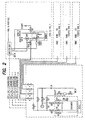
- Fig. 2 shows a schematic view of an ultra pure or contamination sensitive chemical dispensing system which has only a single pressurized bulk chemical supply tank and a single chemical supply ampule.
- Fig. 3 is a block diagram of the electrical and chemical sections in the cabinet which are used to operate the system.
- the upper electrical section of the system includes a programmable logic controller (PLC).
- PLC controller contains the CPU, analog inputs, digital inputs and outputs, and power supply.
- the controller is connected to an analog input which takes the signals directly from the volume or weight scales and pressure transducers (P1 and P2).
- the analog signals are converted into digital signals for the controller computer which controls the operation of the solenoid valves in valve manifold 114.
- the PLC modules connect to the interface board.
- the interface board contains the required power supplies and interface electronics. Pressure transducer and scales are connected to the analog card of the PLC.
- the vacuum switch, spill sensor and door sensor inputs are connected to the interface board.
- the interface electronics also interprets the signals coming from the associated processing equipment. On command from the PLC, the interface board sends signals to a bank of solenoid valves.
- the solenoid valves control compressed air flow to the pneumatic valves in the plumbing manifold.
- the solenoid valve manifold 114 receives compressed air and selectively delivers the compressed air to the above-described pneumatic valves contained in the manifold assembly 58 via individual tubular connections 116.
- one solenoid valve is operably paired with a respective one of the pneumatic valves in the manifold 58.
- the controller dictates operation of the solenoid valves in manifold 114, and, therefore, the pneumatic valves V1-V15 in manifold 58.
- the controller will also signal and prompt the system operator via the touch screen monitor as to tasks which must be manually performed.
- the present invention provides a modular automatic refill system which does not require a vacuum pump but is safe for an ultra high purity, pyrophoric metalorganic (PMO) chemicals.
- This system also does not require the removal of the working cylinder (bubbler) from the working apparatus and controls the plurality of chemical receiving bubblers independently of one another.
- the system also has separate control modules for each bubbler which may be removed from the automatic refill system during operation of the remaining modules without damaging or harming the microprocessor of the removed module.
- Another feature of the present invention is that the automatic refill system can be utilized to fill more than one bubbler with the ultra high purity chemical from a single bulk container.
- the degree of saturation of the carrier gas by the liquid chemical replenished by the subject automatic refill system does not change.
- Other inert carrier gases do not dilute the commonly used hydrogen carrier gas.
- every digital input/output is galvanically isolated from the microprocessor. All of the modules are separate, stand-alone units with their own microprocessor and peripheral electronics. When one module controlling one bubbler malfunctions, the remaining modules and bubbler controllers continue to work normally. The replacement of a malfunctioning module or bubbler does not interfere with the operation of the remaining modules, bubblers, and their associated metalorganic chemical vapor deposition (MOCVD) machines. The separate modules are quickly and easily replaced since they are designed as pull out/plug in units. Each microprocessor control module causes its bulk chemical transfer line to be drained of PMO chemical into its corresponding working container, and thereby reducing the risk of PMO fire.
- MOCVD metalorganic chemical vapor deposition
- the chemical transfer lines are back-filled between filling modes, with ultra-high purity hydrogen gas.
- Working containers or bulk chemical supply tanks are fitted with redundant level detectors, so arranged to signal extreme level conditions.
- a gas venturi is used to eliminate PMO vapors from transfer lines prior to a change-out of the bulk chemical supply container.
- This modular automatic refill system does not upset the temperature of the liquid chemical in the receiving bubbler and, therefore, the saturation level of the exiting gas is not significantly disturbed.
- the bulk containers are outfitted to allow the use of a helium leak detector. In this way the system can avoid atmospheric contamination, maintaining product purity after the change-out of a bulk cylinder. There is no need to remove the ultra high purity PMO chemical bubblers from the liquid temperature baths of the MOCVD machine to refill them with the chemical, nor is there a necessity to install new bubblers in their place so that the operation of the corresponding MOCVD machines is not affected during the automatic refilling operation and so that the chance of accidental fires is sharply reduced.
- the PMO transfer lines are cleared of PMO liquid chemical during the normal operating mode of the MOCVD machine between refilling modes of operation of the refill system; and that hydrogen gas is back-filled into the transfer lines between refilling modes and the MOCVD machine's operating carrier gas is otherwise undisturbed. That back-diffusion of air into the manifold during standby mode of the refill system is eliminated, and metal oxide formation in and contingent to the manifold is avoided.
- a venturi coupled to valve V16 is employed to remove hazardous PMO chemical vapors from transfer lines before effecting bulk cylinder change-outs.
- a modular automatic chemical refill system which permits fast and easy replacement of damaged or malfunctioning modules within the automatic refill system, without affecting the operation of the remaining modules; so that any of a plurality of bubblers in the system can continue to operate and supply chemical from the bubblers to the corresponding MOCVD machines without interruption.
- the modular automatic refill system senses the level of liquid chemical in each bubbler and automatically refills the liquid chemical in the bubblers to an operating level without requiring removal of the bubblers from their corresponding liquid temperature baths or without significantly affecting the temperature, gas composition and liquid PMO chemical saturation level of the carrier gas, nor introducing any oxygen into the refill system or the MOCVD machine.
Landscapes
- Engineering & Computer Science (AREA)
- Physics & Mathematics (AREA)
- Mechanical Engineering (AREA)
- General Engineering & Computer Science (AREA)
- Electromagnetism (AREA)
- Fluid Mechanics (AREA)
- General Physics & Mathematics (AREA)
- Thermal Sciences (AREA)
- Feeding, Discharge, Calcimining, Fusing, And Gas-Generation Devices (AREA)
- Chemical Vapour Deposition (AREA)
- Cleaning Or Drying Semiconductors (AREA)
Description
- The present invention relates to a system for supplying ultra pure and contamination sensitive chemicals to production lines for forming semiconductors, fiber optics, or like components. More particularly, this invention relates to a system carrying pyrophoric chemicals which allows the production line to operate continuously, and without interruption.
- The manufacture of semiconductors, fiber optics, and the like components, typically requires production lines with systems for supplying high purity processing chemicals to diffusion furnaces, either directly or in carrier gases. Processing chemicals are liquids which may be directly injected into the processing stations, or which may be carried to the processing stations in a carrier gas. Direct chemical injection may be from bulk supply tanks, or may be from smaller supply containers which will be periodically refilled by bulk supply tanks. When the chemicals are applied by means of carrier gases, the liquid chemicals will be contained in temperature-controlled ampules or work cylinders, called "bubblers". A stream of an inert carrier gas, such as nitrogen, helium, or the like, is injected into the bubbler ampules. The inert carrier gas bubbles upwardly through the liquid chemical in the bubbler ampule and creates a chemical-saturated carrier gas atmosphere in the ampule in the space above the supply of liquid chemical contained therein. The chemically saturated carrier gas is continuously drawn out of the bubbler and transferred into the component processing station, such as a diffusion furnace, as noted above.
- The processing lines depend on a continuous supply of the chemicals being delivered from the chemical source in order to operate properly and efficiently. If the supply of the processing chemicals is interrupted, the production line must be shut down, and the diffusion furnace must be placed in a "idle" mode. If the chemical ampules are depleted of processing chemicals, they must be removed from the production line and replaced with freshly filled ampules.
- To avoid the necessity of removing a bubbler ampule from the production line, additional bulk chemical supply containers may be incorporated into the production line. When a single bulk supply container is used in the production line, it must be periodically refilled with processing chemicals. The line must be shut down while the bulk supply container is refilled. The line can be run for a longer time period due to the use of the bulk supply container, however, the line still must be periodically shut down when the bulk supply container is depleted. When two bulk supply containers are used, one is a fixed container and the other is a replaceable mobile container. The ampule is replenished with chemicals from the fixed bulk container, and the fixed bulk container is refilled with chemicals from the replaceable, or shuttle, bulk container. The fixed bulk container is typically positioned on a scale or connected to a load cell so that the volume of chemical in the fixed bulk container is continuously monitored. Signals are transmitted to the system microprocessor controller or "junction box" which are indicative of the volume of chemical remaining in the fixed bulk container. The microprocessor controller manages about 2 points of use. For each point of use, there are four level sensors, i.e., empty, low, high or overflow. The low or high corresponds to the "start" and "stop" sensors which trigger the signal initiation to fill the ampule or the removal of the request. The empty or overflow ("overfill") sensors are emergency sensors if the start and stop sensors fail. The supply voltage for the sensor circuit is about +24 volts. All level sensors connect to +24 volt when dry. A pressure switch generates a junction box alarm when there is not enough clean dry air (CDA) pressure. The electrical connections include main power and interface connections. Power is configured for 110VAC or 230VAC. A circuit breaker located where the main power is connected can be used to shut off all power to the unit. Twin fans act to cool the electronics area of the unit. A dispense request connector is used to interface with the process equipment, in addition to supplying status and alarm signals.
- Typically, when the fixed bulk container is seen to be 75% full, the controller activates a chemical transfer valve system which transfers chemical from the shuttle bulk container to the fixed bulk container, and when the fixed bulk container has been refilled, the controller deactivates the chemical transfer valve system. Thus, the fixed bulk supply container will be refilled several times before the shuttle supply container must be refilled. When the shuttle bulk supply container has been substantially emptied, the shuttle container is removed from the production line and is refilled at an off-site chemical supply repository, which is typically far removed from the processing plant.
- The use of fixed and shuttle bulk chemical supply containers has proven to be functionally operative, but it would be desirable to be able to provide an alternative replenishment system for the chemical ampules; and even more desirable to provide a chemical replenishment system with a controller microprocessor which can operate the system in alternative chemical replenishment modes, one having a fixed and a replaceable bulk chemical supply containers, and the other having two replaceable bulk chemical supply containers.
- Transportation of ultra high purity or ultra sensitive chemicals within the production lines require additional safeguards. For that reason, pyrophoric chemicals capable of self-ignition when it is exposed to air, are rarely in production lines. Automatic liquid replacement or refill systems for liquids have been utilized in other industries where the purity requirements of the liquid are far less stringent, and where pyrophoric reactions and extreme air (oxygen and moisture) sensitivity are not commonly encountered. Moreover, these replacement systems have been based upon measuring the weight of the liquid in the working container at comparative points in time or by using a time filling sequence to ensure the proper volumetric quantity is delivered. None of the systems were designed to work with the stringent requirements needed for ultra high purity or contamination sensitive chemicals in the compound semiconductor industry, and where the systems must accommodate pyrophoric metalorganic chemicals with their need to minimize fire, and eliminate air contamination hazards.
- Additionally, automatic chemical refill systems servicing a multiple number of temperature controllers and their bubblers from one central refill control system have suffered from the problem that when one temperature controller has experienced problems or malfunctions in the system, all of the refill lines have to be shutdown until the problem is corrected, In current practice, most chemical refill systems are capable of operating up to four temperature controllers concurrently to supply vapors to a corresponding number of deposition tools. Thus, a repair required of just one temperature controller in the refill system could cause all of the temperature controllers in the system to be shutdown.
- The bubblers are held in liquid, temperature-controlled baths, and must be periodically replaced based on the usage of the ultra high purity pyrophoric metalorganic (PMO) source chemical. The amount of chemical used is a function of the degree of saturation of the hydrogen carrier gas carrying the PMO chemical to the metalorganic chemical vapor deposition (MOCVD) reactor and the quantity of carrier gas used. Typical carrier gases are nitrogen, argon, or helium, but the preferred gas for PMO CVD is ultra high purity hydrogen. Some typical chemicals utilized in bubblers are trimethylgallium (TMG), triethylgallium (TEG), trimethylaluminum (TMA) and dopant chemicals, such as dimethylzinc (DMZ) and diethylzinc (DEZ). When the chemical in the bubbler is depleted, the bubbler has to be removed from the temperature bath and refilled at a remote site.
- In the typical compound semiconductor prior art process which requires use of fresh liquid pyrophoric metalorganic (PMO) chemicals, a replacement bubbler is inserted into the liquid temperature bath. This replacement of the chemical, however, requires physical removal of the depleted bubbler from the liquid temperature bath and requires the MOCVD machine to be shut down for a period of time while the change is being made. Normally the MOCVD machine's reactor zone temperature is lowered during these periods of non-operation. Prior to recommencing use of the replenished chemical, both the bubbler and the machine's reactor zone must be reheated to their standard operating temperatures. Routinely, test samples are next run through the process to ensure that the replenished chemical is not contaminated, and that it is otherwise acceptable for use in the process, prior to resuming the production operation. The total, liquid chemical replacement process can take from two to eight hours, depending upon the chemical involved and the end product being made by the MOCVD machine.
- These problems are solved in the design of the present refill system by providing a modular automatic refill system where the liquid level sensors operate completely independent from each other to automatically refill the bubbler in its liquid temperature bath without removing the bubbler from the bath.
- This invention relates generally to a system to automatically refill a liquid from a bulk container to a smaller receiving container without contamination. More specifically, it relates to a modular system providing fresh liquid pyrophoric metalorganic (PMO) chemicals through an automatic refill to a plurality of working cylinders (in their corresponding temperature controlled baths) that supply a vapor to a corresponding number of metalorganic chemical vapor deposition (MOCVD) machines. Source liquid chemical cylinders have been utilized in the compound semiconductor industry to supply chemicals directly or indirectly via carrier gases that are either partially or fully saturated with the particular PMO chemical as a function of the liquid chemical cylinder's temperature and pressure and the rate of carrier gas flow through the cylinder. Various ultra-high purity liquid PMO chemicals, including those commonly called dopants, are required for this industry.
- Additionally, in conventional MOCVD reactors, it is common practice to use a vacuum pump to remove residual PMO vapors from transfer lines, before removing a cylinder or bubbler, to replace it, or to inspect it. The use of a vacuum pump has several disadvantages:
- A vacuum pump requires that a trap be used to condense and thereby remove volatile chemicals before they reach the pump, in order to avoid corrosion and decomposition of the chemicals with formation of deposits on the working surfaces and moving parts of the pump.
- A vacuum pump generates heat, which can interfere with temperature control of the system.
- A vacuum pump, and attendant parts, supports and trap, requires space in the working area.
- A vacuum pump is an expensive piece of equipment, which requires regular maintenance. Its trap requires regular inspection, replacement of low-temperature coolant, and regular removal of and disposal of the condensed, hazardous PMO chemicals. In addition, the vacuum pump requires regular changes of its sump oil due to the build-up of PMO's in the oil, in spite of the aforementioned trap, which is never 100% efficient.
- The use of the venturi for the present invention is not only unique, but often overlooked. This is due to the fact that under normal conditions, the vacuum that can be generated by the venturi is not sufficient to evaluate all of the pyrophoric chemicals so one could safely open the system for a container exchange. Thus, based on theoretical calculations, this type of a system would not work. However, the present inventors have incorporated the use of the venturi with a dilution/purge routine that surprisingly allows for all of the chemical to be removed from the system. Thus, a safe container exchange is possible. This avoids the conventional use of vacuum pumps or other such expensive equipment to achieve the desired vacuum.
- The disadvantages of using a vacuum pump are overcome in the present invention by the forementioned use of a venturi to remove residual PMO chemical vapors. The use of a venturi for the removal of residual PMO vapors has several advantages:
- A venturi requires no moving parts for its operation, and therefore does not require a trap be installed to remove volatile chemicals before they reach the venturi. The volatile chemicals treated by the venturi in this invention are exhausted directly through the venturi and are combined for disposal with the normal exhaust from the MOCVD tool.
- A venturi generates little or no heat, and therefore has no effect on the temperature control system of this invention.
- A venturi requires very little space within the system's cabinet. A venturi's small size allows further efficiency by reducing the volume of gases contained in shorter lengths of connecting lines.
- A venturi is a very simple device, is inexpensive to install, and requires little or no maintenance.
- A further improvement beyond using a venturi vacuum source with PMO's is the addition of a valve at the exhaust of the venturi, a feature that is lacking in
European Patent Application No. EP 0 723 214 A1, to Goossens et al . PMO's commonly decompose in the presence of oxygen or other contaminants to form an intractable, solid residue. Without this additional valve, it is possible for oxygen or other contaminants to diffuse down the exhaust line to the venturi and react with any PMO residues that might remain there. Repeated use of the venturi followed by such residue formation could eventually lead to reduced effectiveness or even blockage of the venturi. With the additional valve, such contamination is avoided and the venturi is kept free of residue. This extends the functional lifetime of the venturi, and lengthens the time between preventative maintenance cycles. - The present invention is directed to a chemical refill system which comprises: (a) at least one first chemical reservoir; (b) at least one second chemical reservoir; (c) a means for supplying gas to the chemical refill system; (d) a conduit means for connecting the means for supplying gas, the first chemical reservoir, and the second chemical reservoir; (e) at least one venturi comprising a gas inlet, a gas outlet and an exhaust gas outlet, the venturi being disposed between the means for supplying gas and the first and second reservoirs; and (f) at least one valve disposed about the exhaust outlet, wherein the valve prevents diffusion of oxygen or any contaminants into the system. Preferably, the first chemical reservoir is a bulk chemical supply tank and the second chemical reservoir is an ampule and receives chemical from said first chemical reservoir and delivers chemical to a means for applying the chemical. The conduit means connects the chemical refill system to a means for applying the chemical and comprises a plurality of transfer lines and a plurality of valves.
- One embodiment of the chemical refill system further comprises a volume sensor which is capable of monitoring the volume of chemicals remaining in the first and second chemical reservoir. The volume sensor is operable to monitor the volume of chemical in the first and second chemical reservoirs using one selected from the group consisting of: optical sensor, thermal conductance sensor, capacitance sensor, weight scale, sonic sensor, weight scale, and nitrogen back pressure sensor, Preferably, the volume sensor is an optical sensor utilizing a glass rod encased in the first and second chemical reservoirs or a thermal conductance sensor utilizing a thermistor encased in the first and second chemical reservoirs.
- Another embodiment of the chemical refill system further comprises a liquid temperature sensor in each of the first and second chemical reservoirs. A further embodiment of the chemical refill system comprises a microprocessor controller means for selectively operating the chemical refill system. Preferably, the microprocessor controller means is a programmable logic controller. Also preferably, the microprocessor controller means further comprises a set of solenoid valves.
- One embodiment of the chemical refill system comprises two of the first chemical reservoir and two of the second chemical reservoir. The chemical refill system for this embodiment has a microprocessor controller means which selectively operates the system in a fixed/shuttle mode which mode involves the use of a fixed first chemical reservoir and the use of a shuttle first chemical reservoir, or in a shuttle/shuttle mode which mode involves the use of a plurality of shuttle first chemical reservoirs.
- The present invention is also directed to a process for transporting a chemical: (a) using a chemical refill system further comprising a microprocessor controller means which comprises a plurality of independently operating microprocessor-controlled modules, each module being matched electrically to each first chemical reservoir, and programmed to control the refilling operation of said corresponding first chemical reservoir; (b) monitoring the volume of chemical within said corresponding first chemical reservoir; wherein each independently operating microprocessor-controlled module may be removed from the microprocessor controller without interrupting the operation of the remaining microprocessor-controlled modules and their corresponding first chemical reservoirs and wherein each microprocessor-controlled module; (c) sensing an alarm condition from a volume sensor; and (d) causing through the sensing of step (c) either a refill of that working reservoir or a shut down of that automatic refill line, and wherein all microprocessor-controlled modules, upon sensing a low level or low pressure alarm condition from said sensor in the first chemical reservoir will act synchronously to cease operation from that first chemical reservoir.
- Another embodiment of the invention further comprises at least two check valves, wherein the check valves control the conduit means between each of said first chemical reservoir.
- In a further embodiment of the invention, the chemical refill system transports pyrophoric chemicals. Preferably, the chemical refill system transports liquid pyrophoric metalorganic chemicals.
-
- Fig. 1 is a schematic view of the system of the present invention for dispensing ultra high purity or contamination sensitive chemicals into a processing station in the production line having eight points of use in the bubbler section; and
- Fig. 2 is a schematic view of the system of the present invention for dispensing ultra high purity or contamination sensitive chemicals into a processing station in the production line having four points of use in the bubbler section.
- Fig. 1 is a schematic view of an ultra pure or contamination sensitive chemical dispensing system which forms a part of a production line for processing semiconductors, or the like. The left side of Fig. 1 shows the bulk chemical supply tanks and the valving and conduit scheme for the purge gas and chemical refill manifold. The bulk chemical supply tanks are denoted by the
numerals 50 and 52. One or both of them can be shuttle tanks. When only one tank is a shuttle tank, the other will be a fixed tank which is not designed to be removed from the cabinet 48. In either case, the cabinet 48 will be provided withscales tanks 50 and 52. The cabinet assembly is thus capable of being used in a shuttle/shuttle mode, and is also capable of being used in a fixed/shuttle mode. Thescales tank 50 and 52 at all times, and are operable to send appropriate signals to the controller so that the shuttle tank can be removed and replaced with a new shuttle tank in a manner which allows the production line to remain in continuous operation for an indeterminate time period. - The manifold includes a plurality of
outlet passages tanks 50 and 52 may be selectively transferred to bubblers which require chemical replenishment.Transfer passages tanks 50 and 52, respectively, to theoutlet passages transfer passages tanks 50 and 52. Valves V5 and V6 are also actuated by the system controller. The chemical is forced out oftanks 50 and 52 by means of a tank-pressurizinggas source 55. Pressure gauges P1 and P2 are used to monitor the gas pressure in thetanks 50 and 52, respectively. The gas source is operable to selectively provide a pressurized stream of an inert dry gas, such as helium or nitrogen, totanks 50 and 52 through passages 72 and 74. The flow of pressurizing gas totanks 50 and 52 through passages 72 and 74 is controlled in part by valves DV3 and DV6; and the transfer of chemicals fromtanks 50 and 52 topassages - A second source of pressurized gas is included in the system for use in applying a vacuum to the manifold assembly. The pressurized gas source opens into a line which is controlled by valve V15 and when valve V15 is open, the gas stream passes through
venturi nozzle 78 so as to impose a vacuum inline 80 which opens intoventuri nozzle 78. The venturi pulls vacuum on the manifold so that there is no need to connect the system to an external supply of vacuum. An additional valve V16 is located at the exit of the venturi. Valve V16 prevents back diffusion of oxygen or any moisture or air that may be detrimental to ultra pure or contamination sensitive chemicals. - The following is a description of the valving sequence for transferring chemical from
tank 50 to one or more ofoutlet passages outlet passages tank 50, pressurizing the latter sufficiently to force the chemicals up throughtube 51 intoline 68 and out through the opened outlet passages. The chemical is transferred tobubbler ampule 4 through aline 46 which connects with anextended tube 41 via avalve 45 which remains open at all times during normal operation of the system. The transferred chemicals enterampule 4 through the open end oftube 41. When the appropriate fill level is detected in the ampule, the controller automatically closes valves V5 and V9 along with the opened outlet valve. As previously noted,scale 54 monitors the amount of chemicals remaining intank 50, and when the chemical amount reaches a predetermined minimal amount, the controller will provide a signal to the system operator that the tank is to be removed from the cabinet when the system is a shuttle/shuttle system. - When the system is operating in a fixed/shuttle mode such that
tank 50 is the fixed tank and tank 52 is the shuttle tank,scale 54 will signal the controller when the chemical level intank 50 has reached a refill level, preferably about 75% of capacity, and the controller will open the correct valves in the system so as to effect a transfer of chemical from tank 52 totank 50. Assuming at this point that all of the valves except DV2, DV3, DV6, and DV7 are closed, the controller will open valves V10, V5, and V6. This will cause the pressurized gas from the gas source to pressurize the tank 52 to the extent needed to force the chemical up throughtube 71 intopassage 70 and through the valves V5 and V6 to line 68. The chemical then flows down throughline 68 intotube 51 and intotank 50. Whenscale 54 signals that sufficient chemical has been transferred into tank 52, the controller closes valves V10, V5, and V6 to halt movement of the chemical from tank 52 to 50. Obviously, if tank 52 were the fixed tank andtank 50 were the shuttle tank in a fixed-shuttle system, the transfer would involve manipulation of valve V9 rather than valve V10. The other operative valves would remain the same. - The microprocessor controller when operating the system in the shuttle/shuttle mode, periodically actuates the valves to open one of the second and third chemical transfer lines upon receipt of the need-to-add level of chemical signal from the level detectors and, after receipt of a tank-empty signal from one of the volume sensors, to periodically subsequently actuate the valves to open the other of the second and third chemical transfer lines upon receipt of subsequent need-to-add level of chemical signals from the level detectors, and to keep the valves in a condition which holds the first chemical transfer line in a closed condition.
- In both the fixed/shuttle and shuttle/shuttle modes of operation, there will be an operating protocol for exchanging an empty tank for a full tank. The following is an explanation of the protocol. The empty tank to be replaced will be the shuttle tank in the fixed/shuttle mode, and alternating ones of the tanks in the shuttle/shuttle mode. Assuming that tank 52 is the tank to be replaced with a full tank, the controller will be signaled by
scale 56 that tank 52 is empty, i.e., that the chemical level is below the lower end oftube 71. - The general protocol for exchanging empty bulk containers is as follows:
- 1) blowing out the lines of the manifold associated with the bulk container being replaced;
- 2) purging the lines of the manifold associated with the bulk container being replaced;
- 3) flushing inert gas through the connection lines while they are being disconnected from the empty bulk container and then reconnected to the new bulk container;
- 4) purging the lines again; and
- 5) checking the connections for leaks.
- "Blowing out" refers to the removal of liquid in lines of the manifold when the latter are full of chemical. "Purging" refers to the removal of any residual liquid remaining in the lines after the "blowing out" operation. "Flushing" refers to the constant flow of gas through the lines to eliminate line contamination which connections are being made.
- To start the changeover sequence, the controller will open valve V15 so as to direct a stream of compressed gas through
venturi 78 and out through valve V16. This will draw a vacuum in theline 80 and inline 84. The valve V13 is opened to extend the vacuum to tank 52. Valve V8 is opened to direct a stream of pressurized gas from thegas source 55 intolines source 55 thus sweeps throughlines tube 71 and tank 52, and thence throughlines venturi 78, and through valve V16. The valve V16 prevents back diffusion of oxygen or any moisture or air which is detrimental to ultra pure or contamination sensitive chemicals. The dry gas from the gas source will cause any residual chemical inlines - After the system operator signals the system controller that the valves have been closed, the controller will open valve V15 so as to direct a stream of compressed gas through
venturi 78 and out through valve V16. This will draw a vacuum inline 80 and inline 84. Valves V 13 and V 14 are opened to extend the vacuum tolines gas source 55 intolines source 55 thus applies pressure tolines - The above purge cycle of alternately applying vacuum and pressure on the lines and on the tank valves is repeated for the desired number of cycles, typically about ten. Once the necessary purge cycles have been completed; all automatic valves are closed and the controller will open valves V8 and V10 to allow gas to flow through
lines 70 and 74 while the tank is being replaced. The aforesaid prevents air from entering the flexible connection lines while the tank is being removed and a new tank is being installed. The system operator will be instructed to remove tank 52 from the cabinet and to install a full replacement tank. After the system operator has indicated that a new tank has been installed valves V8 and V10 are closed. The controller then opens valve V15 so as to direct a stream of compressed gas throughventuri 78 and out valve V16. This will draw a vacuum in thelines lines - It is noted that the replacement/purge procedure will occur when an empty tank is replaced with a full tank, irrespective of whether the system is operating in the fixed/shuttle, or the shuttle/shuttle mode. In order to operate the system controller in the preprogrammed operating mode, i.e., either the fixed/shuttle, or the shuttle/shuttle operating mode, the system operator need only activate the controller to reassume automatic operation of the system, which is accomplished by means of the keyboard provided in the system.
- The dispensing system includes a chemical temperature controller which contains a
chemical supply ampule 4 from which the ultra pure or contamination sensitive chemical is fed into a semiconductor-processing station via conduit. In the system, the chemical is carried into the processing station in a stream of an inert gas such as nitrogen. The nitrogen gas stream is fed intochemical supply ampule 4 from a line which opens into atube 41 that extends below the surface of the chemical inampule 4. The nitrogen gas stream forms an ascending flow of bubbles which rises up through the liquid chemical into the free space inampule 4, and is operative to humidity and pressurize the free space, and create a pressurized, chemically-humidified stream of processing gas which flows out ofampule 4 throughoutlet 20 and into a line to the processing station. A branch line may be used to temporarily exhaust the processing gas stream from the system during start-up of the process. Valves are selectively operable to control the direction of flow of the processing gas stream. The composition of the atmosphere in the processing station is controlled by gases admitted into the processing station via lines which are regulated by gas mass flow controllers. - The temperature controller includes a heater which maintains the liquid chemical in
ampule 4 at a proper operating temperature. A chemical temperature connected to temperature controller via electrical line sensor and chemical level sensor array are disposed inampule 4. - The level of the chemical in
ampule 4 is sensed in a manner which depends upon the material from which ampule 4 is constructed. For example, when a quartz ampule is used, the level sensing is done by means of a beam emitter and vertically spaced-apart receivers which are located in the portion of the bubbler whereampule 4 is situated. One of the receivers is a start-refill receiver. The emitter sends a signal beam through the quartz ampule to respective receivers located on the opposite side of the ampule. When the liquid level is such that the emitter signal passes through the liquid, the index of refraction of the liquid causes the emitter beam to bend sufficiently so that the start-refill receiver will not "see" the emitter beam. So long as this condition persists, the ampule refill program will not be activated. When the liquid level falls below the emitter signal beam path, the start-refill receiver will sense the signal beam and will transmit a start-refill program-activation signal to the system controller. - In order to ensure that the proper amount of chemical has been added to the ampule during the refill operation, at least one liquid level sensor is provided in the system. The sensors are vertically spaced apart at a predetermined distance. The lowest sensor is the "start refill" sensor. The intermediate sensor is a "stop refill" sensor, and the uppermost sensor is an "overfill" sensor. The stop refill sensor is operable to send a signal to the system controller indicating that the ampule has been properly refilled; and the overfill sensor acts as a backup for the stop refill sensor, and will activate an alarm in the case of an overfill condition. It will be understood that with the quartz ampule, the stop refill and the overfill sensors are operable to signal the system controller when the emitter beam is deflected by passing through the liquid chemical, while the start refill sensor is operable to signal the system controller when the emitter beam is not deflected by passing through the liquid chemical.
- When
ampule 4 is stainless steel, the chemical level is preferably sensed by means of a series of probes which are denoted generally bynumeral 31, and which are inserted into the top of the ampule and extend into the ampule to the area where the chemical level is to be sensed. Each probe preferably consists of a quartz rod with a beveled end. Signal beam emitter/receiver components 47 are mounted on the top of each rod and send a signal beam down through each rod. The signal beams are reflected internally by the beveled ends of the rods when the chemical liquid level is below the ends of the rods. When the beveled end of a rod is immersed in the liquid chemical, the signal beam will be refracted out of the beveled end of the rod into the chemical, and will be scattered throughout the chemical. Thus, when the beveled end of a start-refill rod 49 is immersed in the chemical, its emitter/receiver 47 will not detect the light beam and will not activate the start-refill program. There are three chemical liquid level sensor probes, one 49 for detecting the start-refill level, one 51 for detecting the full level, and one 53 for detecting an overfill level. Emitter/receivers 47 are connected to a sensor circuit or control electronics which are contained in the temperature controller. The control electronics are connected to the system controller via line, the controller being housed in a cabinet which also contains the purge gas and chemical supply manifolds and valves, and the bulk chemical supply tanks. - The controller microprocessor is a preprogrammed microprocessor that has inputted therein operating parameters for the system, and which is operable to moderate and control the various hardware components of the system so as to maintain proper chemical fill level in
reservoir ampule 4; proper operation of the various valves in the system; as well as additional scheduled proper operating parameters, as will be pointed out hereinafter. - The cabinet includes a microprocessor controller section which includes a keyboard and a monitor which are contained in the electrical section of the cabinet, which cabinet section houses the electrical components of the system. A programmable logic controller (PLC) can also be used to operate the controller. With use of a PLC, the subject invention does not require an ADAC Board, and controls a touch screen flat panel display. Using a touch screen flat panel display obviates the need for a keyboard, mouse, disk drive, and internal hard drive. The lower portion of the cabinet contains the two bulk
chemical supply tanks 50 and 52 and has a pair of side-by-side doors which allow access to the bulk supply tanks. The lower portion of the cabinet contains all of the aforesaid chemical and operating fluid flow control manifold and valves. The valves are preferably pneumatic valves which are operated by a source of pressurized air that is located externally of the cabinet and is connected to the manifold system via a transfer line. Control of compressed air flow through a line is accomplished via electrical solenoid valves contained in the electrical section. The sources of pressurized gas are located externally of the cabinet. - The cabinet has electrical and chemical sections which are used to operate the system. The upper electrical section of the system includes the controller computer CPU components such as the monitor, the keyboard, a mouse, a floppy disc drive, and a hard drive; or in the alternative, the touch screen flat panel display. The controller is connected to an analog to digital controller board which takes the analog signals from an interface board that controls the operation of the solenoid valves in valve manifold, and converts the analog signals into digital signals for the controller computer. The interface board is also connected to and receives signals from both of the bulk tank scales or weight sensors; from the ampule fill level sensors via a line; and from the pressure gauges P1 and P2. The solenoid valve manifold receives compressed air from the line and selectively delivers the compressed air to the above-described pneumatic valves contained in the manifold assembly via individual tubular connections. Thus, one solenoid valve is operably paired with a respective one of the pneumatic valves in the manifold. Depending on input received from start/stop signals, the weight scales and the pressure gauges, as well as operator input from the keyboard or mouse, the controller dictates operation of the solenoid valves in manifold, and, therefore, the pneumatic valves V1-V15 in manifold. The controller will also signal and prompt the system operator via the monitor as to tasks which must be manually performed.
- It will be readily appreciated that the same system manifolding containing identical electrical and chemical components when constructed in accordance with this invention will be able to operate in either of two different modes. The only difference will be the operating program contained in a hard drive in the controller computer. Thus a system constructed in accordance with this invention will be usable in a preexisting processing plant which uses either the fixed/shuttle or shuttle/shuttle operating mode. Also, the presence of CV1 and CV2 allows for use of only one bulk supply container, such that a second container is not necessary. The modular automatic refill system is very flexible and permits connection and control of any desired number of bubblers by adjusting the number of modules in the modularly expandable automatic refill system. The increased versatility of the system of this invention will eliminate the need for custom manifolding in a chemical delivery assembly which manifolding is dependent upon the mode of operation of the processing plant. Fig. 2 shows a schematic view of an ultra pure or contamination sensitive chemical dispensing system which has only a single pressurized bulk chemical supply tank and a single chemical supply ampule.
- Fig. 3 is a block diagram of the electrical and chemical sections in the cabinet which are used to operate the system. The upper electrical section of the system includes a programmable logic controller (PLC). The PLC controller contains the CPU, analog inputs, digital inputs and outputs, and power supply. The controller is connected to an analog input which takes the signals directly from the volume or weight scales and pressure transducers (P1 and P2). The analog signals are converted into digital signals for the controller computer which controls the operation of the solenoid valves in valve manifold 114. The PLC modules connect to the interface board. The interface board contains the required power supplies and interface electronics. Pressure transducer and scales are connected to the analog card of the PLC. The vacuum switch, spill sensor and door sensor inputs are connected to the interface board. The interface electronics also interprets the signals coming from the associated processing equipment. On command from the PLC, the interface board sends signals to a bank of solenoid valves. The solenoid valves control compressed air flow to the pneumatic valves in the plumbing manifold. The solenoid valve manifold 114 receives compressed air and selectively delivers the compressed air to the above-described pneumatic valves contained in the manifold assembly 58 via individual tubular connections 116. Thus, one solenoid valve is operably paired with a respective one of the pneumatic valves in the manifold 58. Depending on input received from start/stop signals, the weight scales and the pressure gauges, as well as operator input from the keyboard or mouse, the controller dictates operation of the solenoid valves in manifold 114, and, therefore, the pneumatic valves V1-V15 in manifold 58. The controller will also signal and prompt the system operator via the touch screen monitor as to tasks which must be manually performed.
- It will be readily appreciated that the same system manifolding containing identical electrical and chemical components when constructed in accordance with this invention will be able to operate in either of two different modes. The only difference will be the operating program in the controller computer. Thus a system constructed in accordance with this invention will be usable in a preexisting processing plant which uses either the fixed/shuttle or shuttle/shuttle operating mode. The increased versatility of the system of this invention will eliminate the need for custom manifolding in a chemical delivery assembly which manifolding is dependent upon the mode of operation of the processing plant.
- The present invention provides a modular automatic refill system which does not require a vacuum pump but is safe for an ultra high purity, pyrophoric metalorganic (PMO) chemicals. This system also does not require the removal of the working cylinder (bubbler) from the working apparatus and controls the plurality of chemical receiving bubblers independently of one another. The system also has separate control modules for each bubbler which may be removed from the automatic refill system during operation of the remaining modules without damaging or harming the microprocessor of the removed module. Another feature of the present invention is that the automatic refill system can be utilized to fill more than one bubbler with the ultra high purity chemical from a single bulk container.
- The degree of saturation of the carrier gas by the liquid chemical replenished by the subject automatic refill system does not change. Other inert carrier gases do not dilute the commonly used hydrogen carrier gas.
- Also, for the present system every digital input/output is galvanically isolated from the microprocessor. All of the modules are separate, stand-alone units with their own microprocessor and peripheral electronics. When one module controlling one bubbler malfunctions, the remaining modules and bubbler controllers continue to work normally. The replacement of a malfunctioning module or bubbler does not interfere with the operation of the remaining modules, bubblers, and their associated metalorganic chemical vapor deposition (MOCVD) machines. The separate modules are quickly and easily replaced since they are designed as pull out/plug in units. Each microprocessor control module causes its bulk chemical transfer line to be drained of PMO chemical into its corresponding working container, and thereby reducing the risk of PMO fire. The chemical transfer lines are back-filled between filling modes, with ultra-high purity hydrogen gas. Working containers or bulk chemical supply tanks are fitted with redundant level detectors, so arranged to signal extreme level conditions. A gas venturi is used to eliminate PMO vapors from transfer lines prior to a change-out of the bulk chemical supply container.
- This modular automatic refill system does not upset the temperature of the liquid chemical in the receiving bubbler and, therefore, the saturation level of the exiting gas is not significantly disturbed. Also, the bulk containers are outfitted to allow the use of a helium leak detector. In this way the system can avoid atmospheric contamination, maintaining product purity after the change-out of a bulk cylinder. There is no need to remove the ultra high purity PMO chemical bubblers from the liquid temperature baths of the MOCVD machine to refill them with the chemical, nor is there a necessity to install new bubblers in their place so that the operation of the corresponding MOCVD machines is not affected during the automatic refilling operation and so that the chance of accidental fires is sharply reduced.
- Additionally, the PMO transfer lines are cleared of PMO liquid chemical during the normal operating mode of the MOCVD machine between refilling modes of operation of the refill system; and that hydrogen gas is back-filled into the transfer lines between refilling modes and the MOCVD machine's operating carrier gas is otherwise undisturbed. That back-diffusion of air into the manifold during standby mode of the refill system is eliminated, and metal oxide formation in and contingent to the manifold is avoided. A venturi coupled to valve V16 is employed to remove hazardous PMO chemical vapors from transfer lines before effecting bulk cylinder change-outs.
- These and other objects, features and advantages are obtained by a modular automatic chemical refill system which permits fast and easy replacement of damaged or malfunctioning modules within the automatic refill system, without affecting the operation of the remaining modules; so that any of a plurality of bubblers in the system can continue to operate and supply chemical from the bubblers to the corresponding MOCVD machines without interruption. The modular automatic refill system senses the level of liquid chemical in each bubbler and automatically refills the liquid chemical in the bubblers to an operating level without requiring removal of the bubblers from their corresponding liquid temperature baths or without significantly affecting the temperature, gas composition and liquid PMO chemical saturation level of the carrier gas, nor introducing any oxygen into the refill system or the MOCVD machine.
Claims (19)
- A chemical refill system which comprises:(a) at least one first chemical reservoir (50, 52);(b) at least one second chemical reservoir (4);(c) a means (55) for supplying gas to said chemical refill system;(d) a conduit means (68, 70) for connecting said means (55) for supplying gas, said first chemical reservoir (50, 52), and said second chemical reservoir (4);(e) at least one venturi (78) comprising a gas inlet, a gas outlet and an exhaust gas outlet, said venturi (78) being disposed between said means (55) for supplying gas and said first and second reservoirs (50, 52; 4); and(f) at least one valve (V16), characterised in that it is disposed about said exhaust outlet, wherein said valve prevents diffusion of oxygen or any contaminants into said system.
- The chemical refill system as recited in claim 1, wherein said first chemical reservoir (50, 52) is a bulk chemical supply tank.
- The chemical refill system as recited in claim 1, wherein said second chemical reservoir is an ampule (4) and receives chemical from said first chemical reservoir (50, 52) and delivers chemical to a means for applying said chemical.
- The chemical refill system as recited in claim 1, wherein said conduit means (68, 70) connects said chemical refill system to a means for applying said chemical.
- The chemical refill system as recited in claim 1, wherein said conduit means (68, 70) comprises a plurality of transfer lines (60, 62, 64, 66) and a plurality of valves (V1, V2, V3, V4).
- The chemical refill system as recited in claim 1, wherein said chemical refill system further comprises a volume sensor (54, 56; 31) which is capable of monitoring the volume of chemicals remaining in said first and second chemical reservoir (50, 52; 4).
- The chemical refill system as recited in claim 6, wherein said volume sensor (54, 56; 31) is at least one selected from optical sensor, thermal conductance sensor, capacitance sensor, weight scale, sonic sensor, scale, and nitrogen back pressure sensor.
- The chemical refill system as recited in claim 7, wherein said volume sensor (54, 56; 31) is an optical sensor utilizing a glass rod encased in said first and second chemical reservoirs (50, 52; 4).
- The chemical refill system as recited in claim 7, wherein said volume sensor (54, 56; 31) is a thermal conductance sensor utilizing a thermistor encased in said first and second chemical reservoirs (50, 52; 4).
- The chemical refill system of claim 1, wherein each of said first and second chemical reservoirs (50, 52; 4) further comprises a liquid temperature sensor.
- The chemical refill system as recited in claim 1, wherein said chemical refill system further comprises a microprocessor controller means for selectively operating said chemical refill system.
- The chemical refill system as recited in claim 11, wherein said microprocessor controller means is a programmable logic controller.
- The chemical refill system as recited in claim 1, wherein said chemical refill system comprises two said first chemical reservoirs (50, 52) and two said second chemical reservoirs (3,4).
- The chemical refill system as recited in claim 13, further comprising at least two check valves (CV1, CV2), wherein said check valves control said conduit means (68, 70) between each of said first chemical reservoirs (50, 52).
- The chemical refill system as recited in claim 13, wherein said chemical refill system further comprises a microprocessor controller means which selectively operates said system in a fixed/shuttle mode which mode involves the use of a fixed first chemical reservoir and the use of a shuttle first chemical reservoir, or in a shuttle/shuttle mode which mode involves the use of a plurality of shuttle first chemical reservoirs.
- The chemical refill system as recited in claim 1, wherein said chemical is a pyrophoric chemical.
- The chemical refill system as recited in claim 16, wherein said chemical is a liquid pyrophoric metalorganic chemical.
- A process for transporting a chemical:(a) using a chemical refill system as recited in claim 1, further comprising a microprocessor controller means which comprises a plurality of independently operating microprocessor-controlled modules, each module being matched electrically to each first chemical reservoir, and programmed to control the refilling operation of said corresponding first chemical reservoir (50, 52);(b) monitoring the volume of chemical within said corresponding first chemical reservoir (50, 52); wherein each independently operating microprocessor-controlled module may be removed from the microprocessor controller without interrupting the operation of the remaining microprocessor-controlled modules and their corresponding first chemical reservoirs (50, 52) and wherein each microprocessor-controlled module;(c) sensing an alarm condition from a volume sensor (54, 56; 31); and(d) causing through the sensing of step (c) either a refill of that working reservoir or a shut down of that automatic refill line, and wherein all microprocessor-controlled modules, upon sensing a low level or low pressure alarm condition from said sensor in the first chemical reservoir, will act synchronously to cease operation from that first chemical reservoir (50, 52).
- A method for transporting a liquid chemical comprising the steps of:(a) providing the liquid chemical refill system of claim 1;(b) pressurizing said at least one first liquid chemical reservoir (50, 52) with said carrier gas; and(c) forcing, under pressure, a liquid chemical contained in said at least one first liquid chemical reservoir (50, 52) through said conduit means (68, 70) thereby filling said at least one second liquid chemical reservoir (4) with said liquid chemical.
Applications Claiming Priority (3)
| Application Number | Priority Date | Filing Date | Title |
|---|---|---|---|
| US22305200P | 2000-08-04 | 2000-08-04 | |
| US223052P | 2000-08-04 | ||
| PCT/US2001/023993 WO2002012780A1 (en) | 2000-08-04 | 2001-07-31 | Automatic refill system for ultra pure or contamination sensitive chemicals |
Publications (3)
| Publication Number | Publication Date |
|---|---|
| EP1309820A2 EP1309820A2 (en) | 2003-05-14 |
| EP1309820A4 EP1309820A4 (en) | 2006-03-08 |
| EP1309820B1 true EP1309820B1 (en) | 2007-09-26 |
Family
ID=22834808
Family Applications (1)
| Application Number | Title | Priority Date | Filing Date |
|---|---|---|---|
| EP01965845A Expired - Lifetime EP1309820B1 (en) | 2000-08-04 | 2001-07-31 | Automatic refill system for ultra pure or contamination sensitive chemicals |
Country Status (7)
| Country | Link |
|---|---|
| US (1) | US6435224B2 (en) |
| EP (1) | EP1309820B1 (en) |
| JP (1) | JP2004505758A (en) |
| KR (1) | KR100875090B1 (en) |
| AU (1) | AU2001286404A1 (en) |
| DE (1) | DE60130662T2 (en) |
| WO (1) | WO2002012780A1 (en) |
Families Citing this family (40)
| Publication number | Priority date | Publication date | Assignee | Title |
|---|---|---|---|---|
| US6578203B1 (en) | 1999-03-08 | 2003-06-10 | Tazwell L. Anderson, Jr. | Audio/video signal distribution system for head mounted displays |
| US7210160B2 (en) * | 1999-05-28 | 2007-04-24 | Immersion Entertainment, L.L.C. | Audio/video programming and charging system and method |
| DE50100049D1 (en) * | 2001-03-29 | 2002-12-12 | Cs Clean Systems Ag | Storage container for liquid, high-purity substances with a device for cleaning the connecting pieces and pipes of the storage container |
| US6536485B1 (en) * | 2001-08-31 | 2003-03-25 | O'brien Robert N. | Room temperature hydrogen packaging using a solvent |
| US6734686B2 (en) * | 2002-04-08 | 2004-05-11 | Nanmat Technology Co. Ltd. | Method for detecting quantity variation of high purity liquid chemicals and devices to carry out the method |
| EP1495485A4 (en) * | 2002-04-12 | 2007-10-10 | Fujifilm Electronic Materials | REMOTE MONITORING SYSTEM FOR CHEMICAL LIQUID |
| US7077388B2 (en) * | 2002-07-19 | 2006-07-18 | Asm America, Inc. | Bubbler for substrate processing |
| JP2004053205A (en) * | 2002-07-23 | 2004-02-19 | Japan Air Gases Ltd | Method and apparatus for supplying managed liquefied gas to liquefied gas container |
| AU2003275466A1 (en) | 2002-10-07 | 2004-05-04 | Immersion Entertainment, Llc | System and method for providing event spectators with audio/video signals pertaining to remote events |
| US7593687B2 (en) * | 2003-10-07 | 2009-09-22 | Immersion Entertainment, Llc | System and method for providing event spectators with audio/video signals pertaining to remote events |
| US7021903B2 (en) * | 2003-12-31 | 2006-04-04 | The Boc Group, Inc. | Fore-line preconditioning for vacuum pumps |
| EP1566464B1 (en) * | 2004-02-20 | 2011-04-13 | Cs Clean Systems Ag | Apparatus and method for replenishing a bubbling device |
| US20060107898A1 (en) * | 2004-11-19 | 2006-05-25 | Blomberg Tom E | Method and apparatus for measuring consumption of reactants |
| US20060170760A1 (en) * | 2005-01-31 | 2006-08-03 | Collegiate Systems, Llc | Method and apparatus for managing and distributing audio/video content |
| JP4911555B2 (en) * | 2005-04-07 | 2012-04-04 | 国立大学法人東北大学 | Film forming apparatus and film forming method |
| KR101297004B1 (en) | 2005-04-25 | 2013-08-14 | 도쿄엘렉트론가부시키가이샤 | Liner-based liquid storage and dispensing systems with empty detection capability |
| EP2388231B1 (en) | 2005-06-06 | 2018-09-26 | Entegris, Inc. | Fluid storage and dispensing systems and processes |
| WO2007146892A2 (en) | 2006-06-13 | 2007-12-21 | Advanced Technology Materials, Inc. | Liquid dispensing systems encompassing gas removal |
| KR100855582B1 (en) * | 2007-01-12 | 2008-09-03 | 삼성전자주식회사 | Liquid supply apparatus and method, substrate processing apparatus which has said apparatus, and substrate processing method |
| KR100770361B1 (en) * | 2007-01-17 | 2007-10-26 | (주)지오엘리먼트 | High purity filling method and device for chemical |
| US8795084B2 (en) * | 2007-03-16 | 2014-08-05 | Jason S Bell | Location-based multiplayer gaming platform |
| US8151814B2 (en) * | 2009-01-13 | 2012-04-10 | Asm Japan K.K. | Method for controlling flow and concentration of liquid precursor |
| JP5690498B2 (en) | 2009-03-27 | 2015-03-25 | ローム・アンド・ハース・エレクトロニック・マテリアルズ,エル.エル.シー. | Method for depositing a film on a substrate and apparatus for delivering a vaporized precursor compound |
| US9522773B2 (en) | 2009-07-09 | 2016-12-20 | Entegris, Inc. | Substantially rigid collapsible liner and flexible gusseted or non-gusseted liners and methods of manufacturing the same and methods for limiting choke-off in liners |
| CN102597310B (en) | 2009-11-02 | 2015-02-04 | 西格玛-奥吉奇有限责任公司 | Solid precursor delivery assembly and correlation method |
| TW201117888A (en) * | 2009-11-25 | 2011-06-01 | Hon Hai Prec Ind Co Ltd | Continuous paint supply system and method for continuous paint |
| CN102791383B (en) | 2010-01-06 | 2017-11-14 | 恩特格里斯公司 | Liquid distribution system with degassing and sensing capabilities |
| CA2693567C (en) | 2010-02-16 | 2014-09-23 | Environmental Refueling Systems Inc. | Fuel delivery system and method |
| TW201242670A (en) | 2010-11-23 | 2012-11-01 | Advanced Tech Materials | Liner-based dispenser |
| CN103648920B (en) | 2011-03-01 | 2016-10-05 | 高级技术材料公司 | Nested blow molded liner and overpack and method of manufacture |
| CN102402230B (en) * | 2011-11-29 | 2016-01-06 | 中广核工程有限公司 | Liquid level controlling system in nuclear power station carbonated drink reheating piece-rate system |
| US10087896B1 (en) * | 2012-10-14 | 2018-10-02 | Alberto Martin Perez | Liquefied light hydrocarbon fuel system for hybrid vehicle and methods thereto |
| JP6106525B2 (en) * | 2013-05-22 | 2017-04-05 | 株式会社堀場エステック | Material feeder |
| JP6288026B2 (en) | 2015-09-28 | 2018-03-07 | 株式会社タツノ | Calibration device |
| EP3299776B1 (en) * | 2016-09-26 | 2020-06-03 | Tatsuno Corporation | Calibration apparatus |
| US12392696B2 (en) * | 2018-08-20 | 2025-08-19 | Doug Markle | Gas phase standard preparation device and method of use |
| US11788190B2 (en) | 2019-07-05 | 2023-10-17 | Asm Ip Holding B.V. | Liquid vaporizer |
| US11946136B2 (en) | 2019-09-20 | 2024-04-02 | Asm Ip Holding B.V. | Semiconductor processing device |
| NZ797055A (en) * | 2020-07-13 | 2023-05-26 | Zero Emission Ind Inc | Gaseous fueling system |
| KR20220090958A (en) | 2020-12-23 | 2022-06-30 | 주식회사 이블루 | Pharmaceutical cartridge drying device |
Family Cites Families (30)
| Publication number | Priority date | Publication date | Assignee | Title |
|---|---|---|---|---|
| JPS54108892U (en) * | 1978-01-18 | 1979-07-31 | ||
| DE3175862D1 (en) * | 1980-05-20 | 1987-02-26 | Schumacher Co J C | Chemical vapor delivery system and method for controlling the flow of vapor in a chemical vapor delivery system |
| JPS59189932A (en) * | 1983-04-11 | 1984-10-27 | Nippon Telegr & Teleph Corp <Ntt> | Reactive liquid container |
| US4979545A (en) | 1988-10-31 | 1990-12-25 | Olin Corporation | Bubbler container automatic refill system |
| US4909436A (en) * | 1988-12-12 | 1990-03-20 | The United States Of America As Represented By The Administrator Of The National Aeronautics And Space Administration | Wet atmosphere generation apparatus |
| JP2614338B2 (en) | 1990-01-11 | 1997-05-28 | 株式会社東芝 | Liquid source container |
| US5316181A (en) * | 1990-01-29 | 1994-05-31 | Integrated Designs, Inc. | Liquid dispensing system |
| US5038840A (en) | 1990-07-31 | 1991-08-13 | Olin Corporation | Bubbler container automatic refill system |
| US5148945B1 (en) | 1990-09-17 | 1996-07-02 | Applied Chemical Solutions | Apparatus and method for the transfer and delivery of high purity chemicals |
| US5370269A (en) | 1990-09-17 | 1994-12-06 | Applied Chemical Solutions | Process and apparatus for precise volumetric diluting/mixing of chemicals |
| JPH0692558A (en) * | 1990-09-28 | 1994-04-05 | Otis Elevator Co | Elevator start control device for reducing sway and excessive acceleration at start |
| JPH05177126A (en) * | 1991-10-17 | 1993-07-20 | Furukawa Electric Co Ltd:The | Hazardous liquid supply device |
| US5950693A (en) * | 1993-04-28 | 1999-09-14 | Advanced Delivery & Chemical Systems, Ltd. | Bulk chemical delivery system |
| US5878793A (en) | 1993-04-28 | 1999-03-09 | Siegele; Stephen H. | Refillable ampule and method re same |
| US5964254A (en) * | 1997-07-11 | 1999-10-12 | Advanced Delivery & Chemical Systems, Ltd. | Delivery system and manifold |
| US5607002A (en) * | 1993-04-28 | 1997-03-04 | Advanced Delivery & Chemical Systems, Inc. | Chemical refill system for high purity chemicals |
| US5465766A (en) | 1993-04-28 | 1995-11-14 | Advanced Delivery & Chemical Systems, Inc. | Chemical refill system for high purity chemicals |
| JPH07100364A (en) * | 1993-10-06 | 1995-04-18 | Nippon Gas Kyokai | Raw material gas supply device |
| US5749389A (en) * | 1993-12-22 | 1998-05-12 | Liquid Air Corporation | Purgeable connection for gas supply cabinet |
| JP3197770B2 (en) * | 1993-12-30 | 2001-08-13 | 東京エレクトロン株式会社 | Semiconductor manufacturing equipment |
| US5549142A (en) | 1994-05-27 | 1996-08-27 | Jeffrey P. Beale | Dispensing system for refueling transport containers with cryogenic liquids |
| US5485941A (en) * | 1994-06-30 | 1996-01-23 | Basf Corporation | Recirculation system and method for automated dosing apparatus |
| US5551309A (en) * | 1995-01-17 | 1996-09-03 | Olin Corporation | Computer-controlled chemical dispensing with alternative operating modes |
| US5609191A (en) | 1995-02-06 | 1997-03-11 | Henkel Corporation | Liquid transfer apparatus |
| JP2952371B2 (en) * | 1995-09-08 | 1999-09-27 | 日本航空電子工業株式会社 | Capacitive liquid level meter and liquid level measuring method using the same |
| JP3276277B2 (en) * | 1995-11-29 | 2002-04-22 | 株式会社フジクラ | Liquid material supply device for CVD |
| JPH09205066A (en) * | 1996-01-24 | 1997-08-05 | Sony Corp | Gas generator |
| AU8481798A (en) * | 1997-07-11 | 1999-02-08 | Advanced Delivery & Chemical Systems, Ltd. | Bulk chemical delivery system |
| JPH11131237A (en) * | 1997-10-31 | 1999-05-18 | Sony Corp | Source gas supply method and source gas supply device |
| US6122931A (en) * | 1998-04-07 | 2000-09-26 | American Air Liquide Inc. | System and method for delivery of a vapor phase product to a point of use |
-
2001
- 2001-07-31 DE DE2001630662 patent/DE60130662T2/en not_active Expired - Lifetime
- 2001-07-31 EP EP01965845A patent/EP1309820B1/en not_active Expired - Lifetime
- 2001-07-31 KR KR1020037001629A patent/KR100875090B1/en not_active Expired - Fee Related
- 2001-07-31 AU AU2001286404A patent/AU2001286404A1/en not_active Abandoned
- 2001-07-31 WO PCT/US2001/023993 patent/WO2002012780A1/en not_active Ceased
- 2001-07-31 JP JP2002518028A patent/JP2004505758A/en active Pending
- 2001-08-02 US US09/921,452 patent/US6435224B2/en not_active Expired - Fee Related
Also Published As
| Publication number | Publication date |
|---|---|
| AU2001286404A1 (en) | 2002-02-18 |
| DE60130662D1 (en) | 2007-11-08 |
| WO2002012780A1 (en) | 2002-02-14 |
| KR20030066591A (en) | 2003-08-09 |
| WO2002012780B1 (en) | 2002-04-04 |
| EP1309820A4 (en) | 2006-03-08 |
| DE60130662T2 (en) | 2008-07-17 |
| KR100875090B1 (en) | 2008-12-22 |
| US6435224B2 (en) | 2002-08-20 |
| EP1309820A2 (en) | 2003-05-14 |
| US20020014275A1 (en) | 2002-02-07 |
| JP2004505758A (en) | 2004-02-26 |
Similar Documents
| Publication | Publication Date | Title |
|---|---|---|
| US6435224B2 (en) | Automatic refill system for ultra pure or contamination sensitive chemicals | |
| US6604555B2 (en) | Automatic refill system for ultra pure or contamination sensitive chemicals | |
| EP0723214B1 (en) | Computer-controlled chemical dispenser with alternative operating modes | |
| KR100417659B1 (en) | Chemical delivery system with ultrasonic fluid sensors | |
| US6629627B1 (en) | Level control systems for high purity chemical delivery systems | |
| US4979545A (en) | Bubbler container automatic refill system | |
| US5038840A (en) | Bubbler container automatic refill system | |
| US20020038676A1 (en) | Refillable ampule and method re same | |
| US6637475B2 (en) | Bulk chemical delivery system | |
| US20070175392A1 (en) | Multiple precursor dispensing apparatus | |
| EP1017613A2 (en) | Bulk chemical delivery system | |
| JPH1057798A (en) | Liquid material supply device and material supply method | |
| KR20070076085A (en) | Chemical Supply System and Method | |
| CN101389787A (en) | Multiple Precursor Distribution Device |
Legal Events
| Date | Code | Title | Description |
|---|---|---|---|
| PUAI | Public reference made under article 153(3) epc to a published international application that has entered the european phase |
Free format text: ORIGINAL CODE: 0009012 |
|
| 17P | Request for examination filed |
Effective date: 20030203 |
|
| AK | Designated contracting states |
Designated state(s): AT BE CH CY DE DK ES FI FR GB GR IE IT LI LU MC NL PT SE TR |
|
| AX | Request for extension of the european patent |
Extension state: AL LT LV MK RO SI |
|
| RBV | Designated contracting states (corrected) |
Designated state(s): DE GB IT NL |
|
| RAP1 | Party data changed (applicant data changed or rights of an application transferred) |
Owner name: FUJIFILM ELECTRONIC MATERIALS USA, INC. |
|
| A4 | Supplementary search report drawn up and despatched |
Effective date: 20060125 |
|
| RAP1 | Party data changed (applicant data changed or rights of an application transferred) |
Owner name: FUJIFILM ELECTRONIC MATERIALS USA, INC. |
|
| GRAP | Despatch of communication of intention to grant a patent |
Free format text: ORIGINAL CODE: EPIDOSNIGR1 |
|
| GRAS | Grant fee paid |
Free format text: ORIGINAL CODE: EPIDOSNIGR3 |
|
| GRAA | (expected) grant |
Free format text: ORIGINAL CODE: 0009210 |
|
| AK | Designated contracting states |
Kind code of ref document: B1 Designated state(s): DE GB IT NL |
|
| REG | Reference to a national code |
Ref country code: GB Ref legal event code: FG4D |
|
| REF | Corresponds to: |
Ref document number: 60130662 Country of ref document: DE Date of ref document: 20071108 Kind code of ref document: P |
|
| PLBE | No opposition filed within time limit |
Free format text: ORIGINAL CODE: 0009261 |
|
| STAA | Information on the status of an ep patent application or granted ep patent |
Free format text: STATUS: NO OPPOSITION FILED WITHIN TIME LIMIT |
|
| 26N | No opposition filed |
Effective date: 20080627 |
|
| PGFP | Annual fee paid to national office [announced via postgrant information from national office to epo] |
Ref country code: GB Payment date: 20110725 Year of fee payment: 11 Ref country code: DE Payment date: 20110727 Year of fee payment: 11 |
|
| PGFP | Annual fee paid to national office [announced via postgrant information from national office to epo] |
Ref country code: NL Payment date: 20110728 Year of fee payment: 11 Ref country code: IT Payment date: 20110725 Year of fee payment: 11 |
|
| REG | Reference to a national code |
Ref country code: NL Ref legal event code: V1 Effective date: 20130201 |
|
| GBPC | Gb: european patent ceased through non-payment of renewal fee |
Effective date: 20120731 |
|
| PG25 | Lapsed in a contracting state [announced via postgrant information from national office to epo] |
Ref country code: DE Free format text: LAPSE BECAUSE OF NON-PAYMENT OF DUE FEES Effective date: 20130201 Ref country code: NL Free format text: LAPSE BECAUSE OF NON-PAYMENT OF DUE FEES Effective date: 20130201 Ref country code: GB Free format text: LAPSE BECAUSE OF NON-PAYMENT OF DUE FEES Effective date: 20120731 |
|
| PG25 | Lapsed in a contracting state [announced via postgrant information from national office to epo] |
Ref country code: IT Free format text: LAPSE BECAUSE OF NON-PAYMENT OF DUE FEES Effective date: 20120731 |
|
| REG | Reference to a national code |
Ref country code: DE Ref legal event code: R119 Ref document number: 60130662 Country of ref document: DE Effective date: 20130201 |