EP1309183A2 - Method and device for detecting the parity of successive fields in an interlaced video signal - Google Patents
Method and device for detecting the parity of successive fields in an interlaced video signal Download PDFInfo
- Publication number
- EP1309183A2 EP1309183A2 EP02292647A EP02292647A EP1309183A2 EP 1309183 A2 EP1309183 A2 EP 1309183A2 EP 02292647 A EP02292647 A EP 02292647A EP 02292647 A EP02292647 A EP 02292647A EP 1309183 A2 EP1309183 A2 EP 1309183A2
- Authority
- EP
- European Patent Office
- Prior art keywords
- parity
- value
- counter
- signal
- parity bit
- Prior art date
- Legal status (The legal status is an assumption and is not a legal conclusion. Google has not performed a legal analysis and makes no representation as to the accuracy of the status listed.)
- Ceased
Links
Images


Classifications
-
- H—ELECTRICITY
- H04—ELECTRIC COMMUNICATION TECHNIQUE
- H04N—PICTORIAL COMMUNICATION, e.g. TELEVISION
- H04N5/00—Details of television systems
- H04N5/04—Synchronising
- H04N5/08—Separation of synchronising signals from picture signals
- H04N5/10—Separation of line synchronising signal from frame synchronising signal or vice versa
Definitions
- the invention relates to the processing of an interlaced video signal, and more particularly the detection of the parity of the frames successive signals of this video signal.
- Frame parity is what allows lines to be interleaved while viewing.
- Line 1 thus starts at the top left of the display and line 313 (for a scan frequency of 50 Hz) or the line 266.5 (for a sweep frequency of 60 Hz) starts at top and middle of the screen.
- the frame parity changes with each frame.
- tops vertical synchronization pulses
- this parity bit is 0 for lines 1 to 312 and 1 for lines 313 to 625.
- this bit is worth 0 for lines 4 to 265 and 1 for lines 266 to 3.
- the invention aims to provide a more satisfactory solution to this parity detection problem especially in applications for digital transmission of video signals.
- the invention therefore proposes a method for detecting parity of successive frames of an interlaced video signal, process in which determines respectively the successive values of the phase signal horizontal, a predetermined whole number n of video lines after successive occurrences of synchronization pulses vertical.
- the phase is noted horizontal not at the time of the vertical synchronization top but a whole number of lines later.
- This number n must be sufficient for the phase locked loop to be able to restore a correct horizontal phase relationship with the input signal.
- the comparison then regains all the reliability it had lost in reason for a possible phase jump at the end of the frame which may occur especially when the source of the video signal is a VCR.
- this predetermined whole number n of lines should not not be too important. Indeed, if the video source is a if it is not playing normally, it may then produce, in addition to the systematic phase jump at the end of the frame, several other phase jumps spaced a few dozen lines apart hardly, which risks modifying the phase again before it is made the statement.
- an arbitrary parity bit which is a signal binary toggling at each start of frame.
- the indication of the parity of the current frame is the current value of the arbitrary parity bit or the current value complemented by this arbitrary parity bit according to the sign of the current value of the parity counter.
- the initialization of the signed parity counter at the value 0 gives almost no inertia to the system at startup, compared to a high value initialization which, if proved that it did not correspond to reality, would lead to waiting a certain number of cycles before the counter takes the correct one sign.
- the inertia which is obtained when the counter has reached a stop value is an advantage for the reliability of the parity indication provided, even if the detection suffers some errors.
- the invention also relates to a detection device parity of successive frames of an interlaced video signal.
- the counter parity has a positive count stop value and a value counting stop negative.
- the control means do not modify not the value of the counter in the presence of a new command from decrement, while when the counter reaches its value positive of counting stop, the control means do not modify not the counter value in the presence of a new command increment.
- the control means advantageously reset the parity counter value at 0 each time synchronization is lost vertical.
- the accounting means that will count the number predetermined lines, include a counter incremented to the rhythm a clock signal, the end of accounting signal being issued when the counter reaches a count value corresponding to the product of said predetermined whole number of lines video n by the average duration of a video line contained in the filter loop of a digital phase locked loop used for horizontal synchronization.
- the invention also relates to an integrated circuit comprising a detection device as defined above.
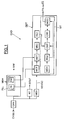
- the reference CVBS designates a video signal analog interleaving from a video source.
- the CVD video circuit which receives the CVBS analog signal, and which can for example be produced in the form of an integrated circuit on a silicon wafer, on the one hand comprises means for horizontal synchronization MSH, which can be of structure and operation known per se. More specifically, these means of horizontal synchronization include a loop PLL phase locked digital output signal SRF reference from an OSC controllable loop oscillator. As is conventional in the matter, this SRF reference signal is the output signal of the horizontal synchronization means MSH, and goes be synchronized with the video signal. In other words, after synchronization and in steady state, the transitions of the SRF signal correspond to horizontal synchronization pulses contained in the video signal.
- the SRF signal is also looped back to the comparator of PLL loop phase.
- the OSC oscillator is controlled, via the filter FB loop (for example of the integral proportional type), by a error signal representative of the phase difference between the video signal CVBS digitized and SRF signal.
- the sampling frequency applied in the means of horizontal synchronization MSH is for example of the order of 27 Mhz corresponding to a sampling clock whose edges amounts are spaced 37 nanoseconds apart.
- the OSC oscillator is then, for example, a cyclic counter incremented at the rate of the signal sampling clock and whose final count value nominal is for example equal to 1727, which corresponds to a video line length of 64 microseconds.
- the value final counting of this cyclic counter can vary around the nominal value so that synchronization on the CVBS video signal.
- the CVD video circuit includes DDT detection means, suitable for detecting the parity of the successive frames of the video signal.
- DDT means which will be discussed in more detail below on structure and function, in particular receive a VSYNC signal representative of the occurrence of a synchronization pulse vertical.
- This VSYNC signal is emitted by means of vertical synchronization MSV of conventional structure and known per se.
- MSV means receive the CVBS video signal digitized after passage in an analogical digital converter CAN.
- the reference SOUT designates the video signal digitized and delayed by a delay corresponding to a video line after passing through RT delay means. This allows to take into account for the delay in developing the VSYNC signal and making coincide with the elaborated parity indication, with the video output SOUT.
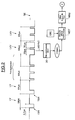
- FIG. 2 We will now also refer to FIG. 2 for describe the structure and operation of the detection means DDT.
- an LV video line located for example in the middle of the frame, begins with a horizontal synchronization pulse (synchronization top horizontal) TSH.
- This TSH pulse extends for example over 4.7 microseconds and at a level that is lower than the SE black level.
- the CVBS signal comprises a series of video lines forming a pre-equalization.
- the impulses of these lines video are shorter and more numerous than TSH pulses.
- the CVBS signal comprises several LVV video lines indicating the change of frame. Specifically, each line LVV has two pulses extending respectively over approximately 30 microseconds. The detection of these LVV video lines will allow the vertical synchronization means MSV to deliver the signal VSYNC.
- MCT accounting means will be triggered (step 20, figure 2).
- These MCT accounting means will record a predetermined number n of video lines, for example 16 video lines.
- these MCT accounting means can have a counter incremented to the rhythm of the clock signal sampling.
- the end of accounting signal is issued when the counter reaches a count value corresponding to the product of the number n by the average duration of a video line, duration which is for example contained in the loop filter FB of the loop to PLL digital phase lock.
- MDT determination means When the counter has delivered its end of count signal, MDT determination means will then determine the value of the horizontal phase of the video signal. To do so, MDT means will examine the value of the cyclic counter forming the oscillator of OSC loop to determine if the horizontal phase is between 1/4 and 3/4 or in the other half. More specifically, in this case, the MDT means will examine whether the value of the counter forming the OSC oscillator is between 0 and 1/4 of the counting limit or between 3/4 of the counting limit and the counting limit on the one hand, or between 1/4 of the counting limit and 3/4 of the counting limit counting on the other hand.
- means of update MMJ will update the value of a parity bit F contained in a first register RG1.
- FIG. 3 we will now refer more particularly to FIG. 3 to describe an embodiment of the method according to the invention allowing delivery by MT processing means (FIG. 1), an indication of the parity of the current frame.
- this indication of the parity of the current frame is the current value of an arbitrary parity bit FA or else the complemented current value FA of this arbitrary parity bit.
- control means MCD will deliver either the arbitrary parity bit FA (step 32) or the parity bit FA (step 31) as a function of the sign of the content of a CTP parity counter.
- the parity bit FA is delivered. While if the counter sign is negative it is the complemented bit FA that is issued.
- MCH means will modify (step 33) the value of the arbitrary parity bit FA contained in a second register RG2, and this for each occurrence of a new frame, that is to say at each occurrence of the signal VSYNC.
- CMP comparison means will then compare (step 35) the value of the arbitrary parity bit FA contained in the second register RG2 with the value of the parity bit F contained in the register RG1 and corresponding to the previous frame. If the two parity bits FA and F are identical (step 36) the control means MCD will increment the CTP parity counter (step 38).
- control means will decrement the CTP counter (step 37).
- the first register RG1 is updated (step 34) after n video lines, as shown above. At that time, the first register RG1 contains the value of the parity bit F associated with the frame current and which will be used for comparison with the parity bit FA during the next frame.
- the parity which is then sent in the digital stream at the output of the DDT device is no longer the detected parity but either the arbitrary parity FA (if the counter is positive) or the reverse FA of this arbitrary parity (if the counter is negative), this arbitrary parity being more reliable than the detected parity.
- the invention is compatible with synchronization horizontal such as that described in the French patent application n ° 01 13905.
- the detection of each horizontal synchronization pulse has a video signal sampling, low-pass signal filtering sampled SN, a thresholding of the filtered signal SNF so as not to leave only pulses whose level is less than one threshold, and a selection according to a selection criterion predetermined, among the residual pulses located inside an observation window centered on a signal transition reference, of that (IMPS) which corresponds to said pulse of horizontal synchronization.
- one analyzes all the tops generated after thresholding and we classify them according to their likelihood level.
- the top with the maximum of likelihood is then selected to update the order of the loop oscillator.
- the selection criterion can include, for example, a criterion of dimension compared to an average dimension (average width) of a horizontal synchronization pulse.
- the selection criterion may include a position criterion relative to the expected position of the synchronization pulse horizontal.
- the expected position of the horizontal synchronization pulse is that of the transition from reference signal.
- the selection criterion can combine the two criteria previously mentioned, i.e. the position criterion and the sizing criteria.
- the weighting can change depending on the applications for adapt in particular to the different types of video source as well as to the quality of this video signal.
- the video source is for example a video recorder, which most likely leads to a phase jump at the end of the frame, we will then promote the width of the synchronization pulses relative to their position.
- CVD video circuit according to the invention can include on the same silicon chip, the means of MSH horizontal synchronization illustrated in Figure 4.
- the analog-to-digital ADC converter is tracked an LPF low pass filter.
- the cutoff frequency of this low pass filter is typically between 200 kHz and 2 MHz, and preferably between 500 kHz and 1 MHz. Such a filter allows to eliminate a good part of the noise and of the sub-carrier of chrominance.
- the filtered SNF sampled signal is then delivered to MSE thresholding means. These carry out a thresholding of the signal of so as to eliminate any part of the SNF signal whose level is above of a threshold.
- This threshold is for example of the order of 50% of the average amplitude measured from a horizontal synchronization top.
- the digital signal SNS therefore includes residual pulses which are considered to be potential horizontal synchronization pulses.
- MSL selection means will then select a IMPS pulse which will be considered as the pulse of horizontal synchronization.
- This IMPS pulse will then be delivered to the PLL phase locked loop comprising the CMPH phase comparator followed by the FB loop filter and the controllable oscillator OSC delivering the reference signal SRF.
- This SRF signal is also looped back to the comparator of CMPH phase and also on the selection means in order to allow selection according to a predetermined criterion.
- the oscillator is therefore controlled via the loop filter FB, by the error signal ERR representative of the deviation phase between the selected IMPS pulse and a transition from SRF signal.
Abstract
Description
L'invention concerne le traitement d'un signal vidéo entrelacé, et plus particulièrement la détection de la parité des trames successives de ce signal vidéo.The invention relates to the processing of an interlaced video signal, and more particularly the detection of the parity of the frames successive signals of this video signal.
La parité des trames est ce qui permet d'entrelacer des lignes
lors de l'affichage. La ligne 1 commence ainsi en haut à gauche de
l'écran et la ligne 313 (pour une fréquence de balayage de 50 Hz) ou la
ligne 266,5 (pour une fréquence de balayage de 60 Hz) commence en
haut et au milieu de l'écran. Par ailleurs pour un signal entrelacé, la
parité des trames change à chaque trame.Frame parity is what allows lines to be interleaved
while viewing.
Jusqu'à maintenant, dans les circuits analogiques, la parité était toujours naturellement gérée par la simple position des impulsions («tops») de synchronisation verticale, ceux-ci survenant soit en début de ligne soit en milieu de ligne. Il n'est donc pas nécessaire d'expliciter la parité, le signal de synchronisation verticale déclenchant directement le retour du spot en haut de l'écran.Up to now, in analog circuits, parity was always naturally managed by the simple position of vertical synchronization pulses (“tops”), these occurring either at the start of the line or in the middle of the line. It is therefore not necessary to clarify the parity, the vertical synchronization signal directly triggering the return of the spot at the top of the screen.
Mais il apparaít désormais nécessaire de transcrire le flux vidéo analogique traditionnel en un flux numérique semblable à celui fourni par les nouvelles sources d'images (DVD, diffusion numérique terrestre par câble, ou par satellite). Ceci permet en effet une extension des fonctionnalités offertes par les téléviseurs, de même qu'une meilleure intégration génératrice d'économies.But it now appears necessary to transcribe the stream traditional analog video in a digital stream similar to that provided by new image sources (DVD, digital broadcast terrestrial by cable, or by satellite). This allows indeed a extension of the functionalities offered by televisions, as well than better integration generating savings.
Cependant, selon la norme régissant cette transcription numérique des images vidéo, la synchronisation verticale n'est plus assurée de la même manière. C'est désormais le basculement d'un bit décrivant la parité qui entraíne la remontée du spot en haut de l'écran.However, according to the standard governing this transcription digital video images, vertical synchronization is no longer insured in the same way. It’s now switching a bit describing the parity which causes the spot to rise to the top of the screen.
Ainsi, avec une fréquence de balayage de 50 Hz (systèmes PAL
et SECAM) ce bit de parité vaut 0 pour les lignes 1 à 312 et 1 pour les
lignes 313 à 625. Pour une fréquence de balayage de 60 Hz (système
NTSC notamment) ce bit vaut 0 pour les lignes 4 à 265 et 1 pour les
lignes 266 à 3. Thus, with a scanning frequency of 50 Hz (PAL systems
and SECAM) this parity bit is 0 for
Il est donc important d'exprimer la parité avec exactitude et la seule position des tops de synchronisation verticale revêt moins d'importance.It is therefore important to express the parity with accuracy and the only position of vertical synchronization tops is less important.
En effet, si l'on venait à se tromper dans la parité d'une trame, cela entraínerait le non-basculement du bit de parité entre cette trame et les trames précédente et suivante. Ce non-basculement peut s'avérer très préjudiciable car il influe directement sur le fonctionnement des récepteurs de signal numérique. En effet, ceux-ci passent alors en recherche de basculement, ce qui se traduit par une image semblant tourner à l'écran (défilement rapide vertical).Indeed, if we were to make a mistake in the parity of a frame, this would cause the parity bit between this frame not toggle and the previous and next frames. This non-tipping can be very detrimental because it directly affects the functioning of digital signal receivers. Indeed, these then go into search for failover, which results in a pretend image turn on the screen (fast vertical scrolling).
Cependant, cette détermination est particulièrement difficile dans le cas des signaux bruités et des signaux issus de magnétoscopes. En effet, dans le premier cas, on est en présence de tops de synchronisation verticale assez perturbés, ce qui vient modifier l'instant auquel on détermine la présence de cette synchronisation verticale. Or la parité dépend uniquement de la position de la synchronisation verticale par rapport à la phase horizontale. Il en résulte donc un risque important d'erreur.However, this determination is particularly difficult in the case of noisy signals and signals from video recorders. Indeed, in the first case, we are in the presence of tops of quite disturbed vertical synchronization, which changes the instant at which the presence of this synchronization is determined vertical. However the parity depends only on the position of the vertical synchronization with respect to the horizontal phase. It there is therefore a significant risk of error.
Pour les magnétoscopes, le problème est inverse. En effet, les signaux ne présentant généralement pas beaucoup de bruit, la position de la synchronisation verticale est assez bien déterminée. En revanche, la phase de la boucle à verrouillage de phase par rapport à celle du signal vidéo peut avoir été faussée dans de grandes proportions en raison de la présence de sauts de phase quelques lignes à peine avant l'apparition de la synchronisation verticale. Dans ces conditions, la relation « top de synchronisation verticale-phase horizontale » est alors à nouveau faussée et il y a un risque d'inversion de parité.For VCRs, the problem is the opposite. Indeed, the generally not very noisy signals, the position of vertical synchronization is fairly well determined. On the other hand, phase of the phase locked loop with respect to that of video signal may have been distorted in large proportions by due to the presence of phase jumps just a few lines before the appearance of vertical synchronization. Under these conditions, the relationship "vertical synchronization top-horizontal phase" is then again skewed and there is a risk of parity reversal.
L'invention vise à apporter une solution plus satisfaisante à ce problème de détection de la parité en particulier dans les applications de transmission numérique de signaux vidéo.The invention aims to provide a more satisfactory solution to this parity detection problem especially in applications for digital transmission of video signals.
L'invention propose donc un procédé de détection de parité des trames successives d'un signal vidéo entrelacé, procédé dans lequel on détermine respectivement les valeurs successives de la phase horizontale du signal, un nombre entier prédéterminé n de lignes vidéo après les occurrences successives des impulsions de synchronisation verticale. Par ailleurs, on met à jour les valeurs successives d'un bit de parité en fonction des valeurs successives de la phase horizontale et on fournit les indications sur la parité des trames à partir des valeurs successives du bit de parité.The invention therefore proposes a method for detecting parity of successive frames of an interlaced video signal, process in which determines respectively the successive values of the phase signal horizontal, a predetermined whole number n of video lines after successive occurrences of synchronization pulses vertical. In addition, we update the successive values of a bit parity according to the successive values of the horizontal phase and we provide the indications on the parity of the frames from the values of the parity bit.
En d'autres termes, selon l'invention, on relève la phase horizontale non pas au moment du top de synchronisation verticale mais un certain nombre entier de lignes plus tard. Ce nombre n doit être suffisant pour que la boucle à verrouillage de phase ait pu rétablir une relation de phase horizontale correcte avec le signal d'entrée. La comparaison regagne alors toute la fiabilité qu'elle avait perdue en raison d'un saut de phase éventuel en fin de trame qui peut se produire en particulier lorsque la source du signal vidéo est un magnétoscope.In other words, according to the invention, the phase is noted horizontal not at the time of the vertical synchronization top but a whole number of lines later. This number n must be sufficient for the phase locked loop to be able to restore a correct horizontal phase relationship with the input signal. The comparison then regains all the reliability it had lost in reason for a possible phase jump at the end of the frame which may occur especially when the source of the video signal is a VCR.
Cependant, ce nombre entier prédéterminé n de lignes ne doit pas être trop important. En effet, si la source vidéo est un magnétoscope et si celui-ci n'est pas en lecture normale, il peut se produire alors, en plus du saut de phase systématique en fin de trame, plusieurs autres sauts de phases espacés de quelques dizaines de lignes à peine, ce qui risque de modifier à nouveau la phase avant qu'on en ait fait le relevé.However, this predetermined whole number n of lines should not not be too important. Indeed, if the video source is a if it is not playing normally, it may then produce, in addition to the systematic phase jump at the end of the frame, several other phase jumps spaced a few dozen lines apart hardly, which risks modifying the phase again before it is made the statement.
En pratique, l'homme du métier saura ajuster ce nombre n en fonction de ces applications. Ceci étant, on pourra choisir un nombre n compris entre environ 10 et environ 50, par exemple 16 ou 32.In practice, the person skilled in the art will be able to adjust this number n by function of these applications. That said, we can choose a number n between about 10 and about 50, for example 16 or 32.
Selon un mode de mise en oeuvre préférentiel de l'invention, permettant notamment de mieux prendre en compte le cas de signaux bruités, on utilise un bit de parité dit arbitraire, qui est un signal binaire basculant à chaque début de trame.According to a preferred embodiment of the invention, allowing in particular to better take into account the case of signals noisy, we use an arbitrary parity bit, which is a signal binary toggling at each start of frame.
Plus précisément, selon ce mode de mise en oeuvre, on change la valeur courante du bit de parité arbitraire à chaque occurrence d'une impulsion de synchronisation verticale. On compare la valeur courante du bit de parité arbitraire avec la valeur du bit de parité déterminée à la trame précédente et on incrémente ou on décrémente la valeur d'un compteur signé dit de « parité » (qui avait été initialisé par exemple à 0) en fonction de ladite comparaison. More precisely, according to this mode of implementation, we change the current value of the arbitrary parity bit at each occurrence of a vertical synchronization pulse. We compare the current value of the arbitrary parity bit with the value of the parity bit determined at the previous frame and we increment or decrement the value of one signed counter called "parity" (which had been initialized for example at 0) as a function of said comparison.
Par ailleurs, l'indication de la parité de la trame courante est la valeur courante du bit de parité arbitraire ou bien la valeur courante complémentée de ce bit de parité arbitraire en fonction du signe de la valeur courante du compteur de parité.Furthermore, the indication of the parity of the current frame is the current value of the arbitrary parity bit or the current value complemented by this arbitrary parity bit according to the sign of the current value of the parity counter.
En pratique, on peut fixer une valeur positive de butée de comptage et une valeur négative de butée de comptage pour le compteur de parité. Ainsi , lorsque le compteur de parité atteint sa valeur négative de butée de comptage, une nouvelle commande de décrémentation se traduit par une non-modification de la valeur de compteur, tandis que lorsque le compteur atteint sa valeur positive de butée de comptage, une nouvelle commande d'incrémentation se traduit pas une non-modification de la valeur du compteur.In practice, we can set a positive stop value of count and a negative count stop value for the parity counter. So when the parity counter reaches its negative count stop value, a new command for decrement results in a non-modification of the value of counter, while when the counter reaches its positive value of counting stop, a new increment command is does not reflect a non-modification of the value of the counter.
Ainsi, selon ce mode de mise en oeuvre, on obtient en sortie des valeurs de la parité bien plus fiables que celles directement issues de la détection, notamment dans le cas des signaux bruités. En effet, il suffit que la détection soit fausse moins d'une fois sur deux pour que le compteur approche de l'une de ces butées et ne change jamais de signe, ce qui amène la disparition complète des erreurs en sortie.Thus, according to this embodiment, we obtain at the output much more reliable parity values than those directly from detection, particularly in the case of noisy signals. Indeed, it it is enough that the detection is false less than half of the time for that the counter approaches one of these stops and never changes sign, which brings about the complete disappearance of the output errors.
Par ailleurs, on réinitialise avantageusement la valeur du compteur à 0 à chaque perte de synchronisation verticale. Et, la première détection qui suit le retour de la synchronisation verticale va alors ramener le compteur soit à 1 soit à -1, ce qui se traduit par une réponse immédiate du point de vue du signe.In addition, the value of the counter at 0 for each loss of vertical synchronization. And, the first detection following the return of vertical synchronization will then bring the counter either to 1 or to -1, which results in a immediate response from the point of view of the sign.
Par ailleurs l'initialisation du compteur signé de parité à la
valeur 0, ne confère quasiment aucune inertie au système au
démarrage, par rapport à une initialisation à une valeur élevée qui, s'il
s'avérait qu'elle ne correspondait pas à la réalité, conduirait à attendre
un certain nombre de cycles avant que le compteur ne prenne le bon
signe. En revanche, selon l'invention, l'inertie que l'on obtient lorsque
le compteur a atteint une valeur de butée , est un avantage pour la
fiabilité de l'indication de parité fournie, même si la détection souffre
de quelques erreurs.In addition, the initialization of the signed parity counter at the
L'invention a également pour objet un dispositif de détection de la parité des trames successives d'un signal vidéo entrelacé. The invention also relates to a detection device parity of successive frames of an interlaced video signal.
Selon une caractéristique générale de l'invention, ce dispositif comprend :
- des moyens de comptabilisation aptes à comptabiliser un nombre entier prédéterminé de lignes vidéo après chaque occurrence d'une impulsion de synchronisation verticale et à délivrer un signal de fin de comptabilisation,
- des moyens de détermination aptes à déterminer respectivement les valeurs successives de la phase horizontale du signal, lors des délivrances successives du signal de fin de comptabilisation,
- un premier registre contenant un bit de parité,
- des moyens de mise à jour aptes à mettre à jour les valeurs successives du bit de parité en fonction des valeurs successives de la phase horizontale, et
- des moyens de traitement aptes à fournir des indications sur la parité des trames à partir des valeurs successives du bit de parité.
- counting means able to count a predetermined whole number of video lines after each occurrence of a vertical synchronization pulse and to deliver an end of counting signal,
- determination means capable of respectively determining the successive values of the horizontal phase of the signal, during successive deliveries of the end of recording signal,
- a first register containing a parity bit,
- updating means able to update the successive values of the parity bit as a function of the successive values of the horizontal phase, and
- processing means capable of providing indications on the parity of the frames from the successive values of the parity bit.
Selon un mode de réalisation de l'invention, les moyens de traitement comportent :
- un compteur signé de parité initialisable à la valeur zéro,
- un deuxième registre apte à contenir un bit de parité arbitraire,
- des moyens aptes à changer la valeur courante du bit de parité arbitraire à chaque occurrence d'une impulsion de synchronisation verticale,
- des moyens de comparaison aptes à comparer la valeur courante du bit de parité arbitraire avec la valeur du bit de parité déterminée à la trame précédente, et
- des moyens de commande aptes à incrémenter ou à décrémenter la valeur du compteur de parité en fonction de ladite comparaison, l'indication de parité de la trame courante étant la valeur courante du bit de parité arbitraire ou bien la valeur courante complémentée de ce bit de parité arbitraire en fonction du signe de la valeur courante du compteur de parité.
- a signed parity counter that can be initialized to zero,
- a second register capable of containing an arbitrary parity bit,
- means capable of changing the current value of the arbitrary parity bit at each occurrence of a vertical synchronization pulse,
- comparison means able to compare the current value of the arbitrary parity bit with the value of the parity bit determined in the previous frame, and
- control means capable of incrementing or decrementing the value of the parity counter as a function of said comparison, the parity indication of the current frame being the current value of the arbitrary parity bit or else the current value supplemented by this bit of arbitrary parity according to the sign of the current value of the parity counter.
Selon un mode de réalisation de l'invention, le compteur de parité possède une valeur positive de butée de comptage et une valeur négative de butée de comptage. Lorsque le compteur atteint sa valeur négative de butée de comptage, les moyens de commande ne modifient pas la valeur du compteur en présence d'une nouvelle commande de décrémentation, tandis que lorsque le compteur atteint sa valeur positive de butée de comptage, les moyens de commande ne modifient pas la valeur du compteur en présence d'une nouvelle commande d'incrémentation.According to one embodiment of the invention, the counter parity has a positive count stop value and a value counting stop negative. When the counter reaches its value counting stop negative, the control means do not modify not the value of the counter in the presence of a new command from decrement, while when the counter reaches its value positive of counting stop, the control means do not modify not the counter value in the presence of a new command increment.
Les moyens de commande réinitialisent avantageusement la valeur du compteur de parité à 0 à chaque perte de synchronisation verticale.The control means advantageously reset the parity counter value at 0 each time synchronization is lost vertical.
Par ailleurs, selon un mode de réalisation de l'invention, les moyens de comptabilisation qui vont comptabiliser le nombre prédéterminé de lignes , comportent un compteur incrémenté au rythme d'un signal d'horloge, le signal de fin de comptabilisation étant délivré lorsque le compteur atteint une valeur de comptage correspondant au produit dudit nombre entier prédéterminé de lignes vidéo n par la durée moyenne d'une ligne vidéo contenue dans le filtre de boucle d'une boucle à verrouillage de phase numérique utilisée pour la synchronisation horizontale.Furthermore, according to one embodiment of the invention, the accounting means that will count the number predetermined lines, include a counter incremented to the rhythm a clock signal, the end of accounting signal being issued when the counter reaches a count value corresponding to the product of said predetermined whole number of lines video n by the average duration of a video line contained in the filter loop of a digital phase locked loop used for horizontal synchronization.
L'invention a également pour objet un circuit intégré comportant un dispositif de détection tel que défini ci avant.The invention also relates to an integrated circuit comprising a detection device as defined above.
D'autres avantages et caractéristiques de l'invention apparaítront à l'examen de la description détaillée de modes de réalisation et de mise en oeuvre, nullement limitatifs, et des dessins annexés sur lesquels :
- la figure 1 est un synoptique schématique d'un mode de réalisation d'un dispositif de détection selon l'invention,
- la figure 2 illustre un mode de mise en oeuvre d'une mise à jour d'un bit de parité à partir d'une mesure retardée de la phase horizontale,
- la figure 3 est un organigramme schématique d'un mode de mise en oeuvre du procédé selon l'invention, et
- la figure 4 illustre schématiquement une variante de réalisation de moyens de synchronisation horizontale qui peuvent être combinés au sein d'un même circuit vidéo avec un dispositif de gestion de parité selon l'invention.
- FIG. 1 is a schematic block diagram of an embodiment of a detection device according to the invention,
- FIG. 2 illustrates a mode of implementation of an update of a parity bit from a delayed measurement of the horizontal phase,
- FIG. 3 is a schematic flowchart of an embodiment of the method according to the invention, and
- FIG. 4 schematically illustrates an alternative embodiment of horizontal synchronization means which can be combined within the same video circuit with a parity management device according to the invention.
Sur la figure 1, la référence CVBS désigne un signal vidéo entrelacé analogique émanant d'une source vidéo.In FIG. 1, the reference CVBS designates a video signal analog interleaving from a video source.
Le circuit vidéo CVD qui reçoit le signal analogique CVBS, et qui peut être par exemple réalisé sous forme d'un circuit intégré sur une pastille de silicium, comporte d'une part des moyens de synchronisation horizontale MSH, qui peuvent être de structure et de fonctionnement connus en soi. Plus précisément, ces moyens de synchronisation horizontale comportent notamment une boucle numérique à verrouillage de phase PLL délivrant un signal de référence SRF issu d'un oscillateur de boucle commandable OSC. Comme il est classique en la matière, ce signal de référence SRF est le signal de sortie des moyens de synchronisation horizontale MSH, et va être synchronisé sur le signal vidéo. En d'autres termes, après synchronisation et en régime établi, les transitions du signal SRF correspondent aux impulsions de synchronisation horizontale contenues dans le signal vidéo.The CVD video circuit which receives the CVBS analog signal, and which can for example be produced in the form of an integrated circuit on a silicon wafer, on the one hand comprises means for horizontal synchronization MSH, which can be of structure and operation known per se. More specifically, these means of horizontal synchronization include a loop PLL phase locked digital output signal SRF reference from an OSC controllable loop oscillator. As is conventional in the matter, this SRF reference signal is the output signal of the horizontal synchronization means MSH, and goes be synchronized with the video signal. In other words, after synchronization and in steady state, the transitions of the SRF signal correspond to horizontal synchronization pulses contained in the video signal.
Le signal SRF est, par ailleurs, rebouclé sur le comparateur de phase de la boucle PLL. L'oscillateur OSC est commandé, via le filtre de boucle FB (par exemple du type proportionnel intégral), par un signal d'erreur représentatif de l'écart de phase entre le signal vidéo CVBS numérisé et le signal SRF.The SRF signal is also looped back to the comparator of PLL loop phase. The OSC oscillator is controlled, via the filter FB loop (for example of the integral proportional type), by a error signal representative of the phase difference between the video signal CVBS digitized and SRF signal.
La fréquence d'échantillonnage appliquée dans les moyens de synchronisation horizontale MSH est par exemple de l'ordre de 27 Mhz correspondant à une horloge d'échantillonnage dont les fronts montants sont espacés de 37 nanosecondes.The sampling frequency applied in the means of horizontal synchronization MSH is for example of the order of 27 Mhz corresponding to a sampling clock whose edges amounts are spaced 37 nanoseconds apart.
Dans l'exemple qui est décrit ici, l'oscillateur OSC est alors, par exemple, un compteur cyclique incrémenté au rythme du signal d'horloge d'échantillonnage et dont la valeur finale de comptage nominale est par exemple égale à 1727, ce qui correspondant à une longueur de ligne vidéo de 64 microsecondes. Bien entendu, la valeur finale de comptage de ce compteur cyclique peut varier autour de la valeur nominale de façon à pouvoir permettre la synchronisation sur le signal vidéo CVBS.In the example that is described here, the OSC oscillator is then, for example, a cyclic counter incremented at the rate of the signal sampling clock and whose final count value nominal is for example equal to 1727, which corresponds to a video line length of 64 microseconds. Of course, the value final counting of this cyclic counter can vary around the nominal value so that synchronization on the CVBS video signal.
Outre les moyens de synchronisation horizontale MSH, le circuit vidéo CVD comporte des moyens de détection DDT, aptes à détecter la parité des trames successives du signal vidéo.In addition to the horizontal synchronization means MSH, the CVD video circuit includes DDT detection means, suitable for detecting the parity of the successive frames of the video signal.
Ces moyens DDT, dont on reviendra plus en détail ci-après sur la structure et la fonction, reçoivent notamment un signal VSYNC représentatif de l'occurrence d'une impulsion de synchronisation verticale. Ce signal VSYNC est émis par des moyens de synchronisation verticale MSV de structure classique et connue en soi. Ces moyens MSV reçoivent le signal vidéo CVBS numérisé après passage dans un convertisseur analogique numérique CAN.These DDT means, which will be discussed in more detail below on structure and function, in particular receive a VSYNC signal representative of the occurrence of a synchronization pulse vertical. This VSYNC signal is emitted by means of vertical synchronization MSV of conventional structure and known per se. These MSV means receive the CVBS video signal digitized after passage in an analogical digital converter CAN.
Par ailleurs, la référence SOUT désigne le signal vidéo numérisé et retardé d'un retard correspondant à une ligne vidéo après passage dans des moyens de retard RT. Ceci permet de prendre en compte le retard dans l'élaboration du signal VSYNC et de faire coïncider l'indication de parité élaborée, avec la sortie vidéo SOUT.Furthermore, the reference SOUT designates the video signal digitized and delayed by a delay corresponding to a video line after passing through RT delay means. This allows to take into account for the delay in developing the VSYNC signal and making coincide with the elaborated parity indication, with the video output SOUT.
On va maintenant se référer également à la figure 2 pour décrire la structure et le fonctionnement des moyens de détection DDT.We will now also refer to FIG. 2 for describe the structure and operation of the detection means DDT.
Sur la partie haute de la figure 2, on a représenté très schématiquement plusieurs lignes vidéo du signal vidéo CVBS. Dans l'exemple décrit, toutes les lignes vidéo ont une longueur de 64 microsecondes.In the upper part of Figure 2, there is shown very schematically several video lines of the CVBS video signal. In the example described, all video lines are 64 microseconds.
Plus précisément, comme il est connu par l'homme du métier, les lignes vidéo peuvent présenter différentes configurations. Ainsi, une ligne vidéo LV, située par exemple en milieu de trame, débute par une impulsion de synchronisation horizontale (top de synchronisation horizontale) TSH. Cette impulsion TSH s'étend par exemple sur 4,7 microsecondes et a un niveau qui est inférieur au niveau de noir SE.More specifically, as is known to those skilled in the art, video lines can have different configurations. So, an LV video line, located for example in the middle of the frame, begins with a horizontal synchronization pulse (synchronization top horizontal) TSH. This TSH pulse extends for example over 4.7 microseconds and at a level that is lower than the SE black level.
Puis, en fin de trame, le signal CVBS comporte une série de lignes vidéo formant une pré-égalisation. Les impulsions de ces lignes vidéo sont plus courtes et plus nombreuses que les impulsions TSH. Then, at the end of the frame, the CVBS signal comprises a series of video lines forming a pre-equalization. The impulses of these lines video are shorter and more numerous than TSH pulses.
Puis, le signal CVBS comporte plusieurs lignes vidéo LVV indiquant le changement de trame. Plus précisément, chaque ligne LVV comporte deux impulsions s'étendant respectivement sur environ 30 microsecondes. La détection de ces lignes vidéo LVV va permettre aux moyens de synchronisation verticale MSV de délivrer le signal VSYNC.Then, the CVBS signal comprises several LVV video lines indicating the change of frame. Specifically, each line LVV has two pulses extending respectively over approximately 30 microseconds. The detection of these LVV video lines will allow the vertical synchronization means MSV to deliver the signal VSYNC.
À partir de cet instant, des moyens de comptabilisation MCT
vont être déclenchés (étape 20, figure 2).From this moment, MCT accounting means
will be triggered (
Ces moyens de comptabilisation MCT vont comptabiliser un nombre n prédéterminé de lignes vidéo, par exemple 16 lignes vidéo.These MCT accounting means will record a predetermined number n of video lines, for example 16 video lines.
Matériellement, ces moyens de comptabilisation MCT peuvent comporter un compteur incrémenté au rythme du signal d'horloge d'échantillonnage. Le signal de fin de comptabilisation est délivré lorsque le compteur atteint une valeur de comptage correspondant au produit du nombre n par la durée moyenne d'une ligne vidéo, durée qui est par exemple contenue dans le filtre de boucle FB de la boucle à verrouillage de phase numérique PLL.Materially, these MCT accounting means can have a counter incremented to the rhythm of the clock signal sampling. The end of accounting signal is issued when the counter reaches a count value corresponding to the product of the number n by the average duration of a video line, duration which is for example contained in the loop filter FB of the loop to PLL digital phase lock.
Lorsque le compteur a délivré son signal de fin de comptage, des moyens de détermination MDT vont alors déterminer la valeur de la phase horizontale du signal vidéo. Pour se faire, les moyens MDT vont examiner la valeur du compteur cyclique formant l'oscillateur de boucle OSC pour déterminer si la phase horizontale se situe entre 1/4 et 3/4 ou dans l'autre moitié. Plus précisément, en l'espèce, les moyens MDT vont examiner si la valeur du compteur formant l'oscillateur OSC se situe entre 0 et 1/4 de la limite de comptage ou entre 3/4 de la limite de comptage et la limite de comptage d'une part, ou bien entre 1/4 de la limite de comptage et 3/4 de la limite de comptage d'autre part.When the counter has delivered its end of count signal, MDT determination means will then determine the value of the horizontal phase of the video signal. To do so, MDT means will examine the value of the cyclic counter forming the oscillator of OSC loop to determine if the horizontal phase is between 1/4 and 3/4 or in the other half. More specifically, in this case, the MDT means will examine whether the value of the counter forming the OSC oscillator is between 0 and 1/4 of the counting limit or between 3/4 of the counting limit and the counting limit on the one hand, or between 1/4 of the counting limit and 3/4 of the counting limit counting on the other hand.
En fonction du résultat de cette comparaison, des moyens de mise à jour MMJ vont mettre à jour la valeur d'un bit de parité F contenu dans un premier registre RG1.Depending on the result of this comparison, means of update MMJ will update the value of a parity bit F contained in a first register RG1.
Plus précisément, si la valeur du compteur se situe entre 1/4 de
la limite de comptage et 3/4 de la limite de comptage, on attribuera par
exemple la valeur 1 au bit de parité F et la valeur 0 sinon. More specifically, if the counter value is between 1/4 of
the counting limit and 3/4 of the counting limit, we will assign by
example the
On va maintenant se référer plus particulièrement à la figure 3 pour décrire un mode de mise en oeuvre du procédé selon l'invention permettant la délivrance par des moyens de traitement MT (figure 1), d'une indication sur la parité de la trame courante.We will now refer more particularly to FIG. 3 to describe an embodiment of the method according to the invention allowing delivery by MT processing means (FIG. 1), an indication of the parity of the current frame.
D'une façon générale, cette indication de la parité de la trame
courante est la valeur courante d'un bit de parité arbitraire FA ou bien
la valeur courante complémentée
Plus précisément, des moyens de commande MCD vont délivrer
soit le bit de parité arbitraire FA (étape 32) ou bien le bit de parité
Ainsi, si le signe du compteur CTP est positif (étape 30) c'est
le bit de parité FA qui est délivré. Tandis que si le signe du compteur
est négatif c'est le bit complémenté
Ainsi, dès l'occurrence du signal VSYNC, une indication de la parité de la trame courante est délivrée.Thus, as soon as the VSYNC signal occurs, an indication of the parity of the current frame is delivered.
Parallèlement à cette délivrance, des moyens MCH vont modifier (étape 33) la valeur du bit de parité arbitraire FA contenu dans un deuxième registre RG2, et ce pour chaque occurrence d'une nouvelle trame, c'est-à-dire à chaque occurrence du signal VSYNC.In parallel with this delivery, MCH means will modify (step 33) the value of the arbitrary parity bit FA contained in a second register RG2, and this for each occurrence of a new frame, that is to say at each occurrence of the signal VSYNC.
Des moyens de comparaison CMP vont alors comparer (étape 35) la valeur du bit parité arbitraire FA contenu dans le deuxième registre RG2 avec la valeur du bit de parité F contenu dans le registre RG1 et correspondant à la trame précédente. Si les deux bits de parité FA et F sont identiques (étape 36) les moyens de commande MCD vont incrémenter le compteur de parité CTP (étape 38).CMP comparison means will then compare (step 35) the value of the arbitrary parity bit FA contained in the second register RG2 with the value of the parity bit F contained in the register RG1 and corresponding to the previous frame. If the two parity bits FA and F are identical (step 36) the control means MCD will increment the CTP parity counter (step 38).
Dans le cas contraire, les moyens de commande vont décrémenter le compteur CTP (étape 37).Otherwise, the control means will decrement the CTP counter (step 37).
Dans le cas où le compteur de parité CTP possède une valeur de butée positive et une valeur de butée négative, une commande d'une nouvelle incrémentation lorsque le compteur CTP a atteint sa valeur de butée positive se traduit par une non modification de ce compteur tandis qu'une commande d'une nouvelle décrémentation lorsque le compteur CTP a atteint sa valeur de butée négative se traduit également par une non modification du compteur.In case the CTP parity counter has a value positive stop and a negative stop value, a command of a new increment when the CTP counter has reached its value of positive stop results in a non modification of this counter while a command for a new decrementation when the CTP counter reached its negative stop value translates also by not modifying the counter.
Parallèlement à cette misé à jour de la valeur du compteur de parité CTP, le premier registre RG1 est mis à jour (étape 34) après n lignes vidéo, comme indiqué ci avant. À ce moment-là, le premier registre RG1 contient la valeur du bit de parité F associé à la trame courante et qui sera utilisé pour la comparaison avec le bit de parité FA lors de la trame suivante.In parallel with this update of the value of the counter of CTP parity, the first register RG1 is updated (step 34) after n video lines, as shown above. At that time, the first register RG1 contains the value of the parity bit F associated with the frame current and which will be used for comparison with the parity bit FA during the next frame.
En d'autres termes, selon l'invention, à chaque nouvelle trame, on compare la valeur du bit FA à la valeur du bit F associé à la trame précédente. Si ces deux bits sont identiques, on incrémente le compteur CTP sinon on le décrémente. Ce compteur, qui est initialisé à 0, est également réinitialisé à 0 lorsque l'on perd la synchronisation verticale.In other words, according to the invention, with each new frame, we compare the value of the bit FA to the value of the bit F associated with the frame previous. If these two bits are identical, the CTP counter otherwise it is decremented. This counter, which is initialized at 0, is also reset to 0 when losing synchronization vertical.
Lorsque ce compteur CTP indique des valeurs positives, on déduit que la parité arbitraire est en phase avec la parité de la trame précédente et inversement lorsque les valeurs sont négatives.When this PTC counter indicates positive values, we deduces that the arbitrary parity is in phase with the frame parity previous and vice versa when the values are negative.
La parité qui est alors envoyée dans le flux numérique en sortie
du dispositif DDT, n'est plus la parité détectée mais soit la parité
arbitraire FA (si le compteur est positif) soit l'inverse
L'invention n'est pas limitée aux modes de réalisation et de mise en oeuvre qui viennent d'être décrits mais en embrasse toutes les variantes.The invention is not limited to the embodiments and implementation which have just been described but embraces all the variants.
Ainsi, l'invention est compatible avec une synchronisation horizontale telle que celle décrite dans la demande de brevet français n° 01 13905.Thus, the invention is compatible with synchronization horizontal such as that described in the French patent application n ° 01 13905.
Plus précisément, si l'on se réfère à la figure 4, la détection de chaque impulsion de synchronisation horizontale comporte un échantillonnage du signal vidéo, un filtrage passe-bas du signal échantillonné SN, un seuillage du signal filtré SNF de façon à ne laisser subsister que des impulsions dont le niveau est inférieur à un seuil, et une sélection en fonction d'un critère de sélection prédéterminé, parmi les impulsions résiduelles situées à l'intérieur d'une fenêtre d'observation centrée sur une transition du signal de référence, de celle (IMPS) qui correspond à ladite impulsion de synchronisation horizontale.More specifically, if we refer to Figure 4, the detection of each horizontal synchronization pulse has a video signal sampling, low-pass signal filtering sampled SN, a thresholding of the filtered signal SNF so as not to leave only pulses whose level is less than one threshold, and a selection according to a selection criterion predetermined, among the residual pulses located inside an observation window centered on a signal transition reference, of that (IMPS) which corresponds to said pulse of horizontal synchronization.
En d'autres termes, selon cette variante de mise en oeuvre, on analyse tous les tops générés après seuillage et on les classe suivant leur niveau de vraisemblance. Le top ayant le maximum de vraisemblance est alors sélectionné pour mettre à jour la commande de l'oscillateur de la boucle.In other words, according to this variant of implementation, one analyzes all the tops generated after thresholding and we classify them according to their likelihood level. The top with the maximum of likelihood is then selected to update the order of the loop oscillator.
Plusieurs critères de sélection peuvent être envisagés.Several selection criteria can be considered.
Le critère de sélection peut comporter par exemple un critère de dimension par rapport à une dimension moyenne (largeur moyenne) d'une impulsion de synchronisation horizontale.The selection criterion can include, for example, a criterion of dimension compared to an average dimension (average width) of a horizontal synchronization pulse.
Ainsi, à titre indicatif, on peut éliminer toutes les impulsions résiduelles dont la largeur est inférieure à un pourcentage prédéterminé de la largeur moyenne d'une impulsion de synchronisation horizontale.So, for information, we can eliminate all the pulses width less than a percentage predetermined of the average width of a pulse of horizontal synchronization.
Une fois cette élimination effectuée, on peut alors par exemple sélectionner l'impulsion résiduelle dont la largeur se rapproche le plus de ladite largeur moyenne.Once this elimination has been carried out, we can then for example select the residual pulse whose width is closest of said average width.
Le critère de sélection peut comporter un critère de position par rapport à la position attendue de l'impulsion de synchronisation horizontale.The selection criterion may include a position criterion relative to the expected position of the synchronization pulse horizontal.
Plus précisément, dans ce cas, la position attendue de l'impulsion de synchronisation horizontale est celle de la transition du signal de référence. On détermine alors l'écart temporel entre chaque impulsion résiduelle et la transition du signal de référence, et on sélectionne celle qui est affectée de l'écart temporel le plus faible.More specifically, in this case, the expected position of the horizontal synchronization pulse is that of the transition from reference signal. We then determine the time difference between each residual pulse and the transition of the reference signal, and we select the one with the smallest time difference.
Le critère de sélection peut combiner les deux critères précédemment mentionnés, c'est-à-dire le critère de position et le critère de dimensionnement.The selection criterion can combine the two criteria previously mentioned, i.e. the position criterion and the sizing criteria.
Ainsi, par exemple, on élimine toutes les impulsions résiduelles dont la largeur est inférieure à un pourcentage prédéterminé de la largeur moyenne d'une impulsion de synchronisation horizontale et on affecte à chaque impulsion résiduelle non éliminée une première note en fonction de sa largeur, la première note la plus élevée correspondant par exemple à une impulsion dont la largeur est égale à ladite largeur moyenne.So, for example, we eliminate all the pulses width less than a percentage predetermined of the average width of a pulse of horizontal synchronization and we assign to each residual pulse not eliminated a first note according to its width, the first the highest note corresponding for example to an impulse whose width is equal to said average width.
Par ailleurs, on détermine l'écart temporel entre chaque impulsion résiduelle non éliminée et la transition du signal de référence. On affecte alors une deuxième note à chaque impulsion résiduelle non éliminée, la deuxième note la plus élevée correspondant par exemple à une impulsion affectée d'un écart temporel nul.In addition, we determine the time difference between each residual pulse not eliminated and the signal transition from reference. We then assign a second note to each pulse residual not eliminated, the second highest corresponding score for example to a pulse affected by a zero time difference.
On affecte ensuite à chaque impulsion résiduelle non éliminée une note finale résultant d'une pondération prédéterminée entre ladite première note et ladite deuxième note.We then assign to each residual pulse not eliminated a final grade resulting from a predetermined weighting between said first note and said second note.
On sélectionne alors l'impulsion résiduelle affectée de la note finale la plus élevée.We then select the residual pulse affected by the note highest final.
La pondération peut évoluer en fonction des applications pour s'adapter notamment aux différents types de source vidéo ainsi qu'à la qualité de ce signal vidéo. Ainsi, en présence d'un bruit important, on favorisera le critère de position par rapport au critère de dimension tandis qu'en présence d'un bruit peu important, on favorisera le critère de dimension par rapport au critère de positionnement. De même, lorsque la source vidéo est par exemple un magnétoscope, ce qui conduit très probablement à un saut de phase en fin de trame, on favorisera à ce moment-là la largeur des impulsions de synchronisation par rapport à leur position.The weighting can change depending on the applications for adapt in particular to the different types of video source as well as to the quality of this video signal. Thus, in the presence of significant noise, we will favor the criterion of position compared to the criterion of dimension while in the presence of a slight noise, we will favor the criterion of dimension in relation to the positioning criterion. Likewise, when the video source is for example a video recorder, which most likely leads to a phase jump at the end of the frame, we will then promote the width of the synchronization pulses relative to their position.
Matériellement le circuit vidéo CVD selon l'invention peut comporter sur la même puce de silicium, les moyens de synchronisation horizontale MSH illustrés sur la figure 4.Materially the CVD video circuit according to the invention can include on the same silicon chip, the means of MSH horizontal synchronization illustrated in Figure 4.
Ainsi, le convertisseur analogique numérique CAN est suivi d'un filtre passe-bas LPF. La fréquence de coupure de ce filtre passe-bas est typiquement comprise entre 200 kHz et 2 MHz, et de préférence comprise entre 500 kHz et 1 MHz. Un tel filtre permet d'éliminer une bonne partie du bruit et de la sous-porteuse de chrominance. So the analog-to-digital ADC converter is tracked an LPF low pass filter. The cutoff frequency of this low pass filter is typically between 200 kHz and 2 MHz, and preferably between 500 kHz and 1 MHz. Such a filter allows to eliminate a good part of the noise and of the sub-carrier of chrominance.
Le signal échantillonné filtré SNF est ensuite délivré à des moyens de seuillage MSE. Ceux-ci effectuent un seuillage du signal de façon à éliminer toute partie du signal SNF dont le niveau se situe au-dessus d'un seuil. Ce seuil est par exemple de l'ordre de 50% de l'amplitude moyenne mesurée d'un top de synchronisation horizontale. Le signal numérique seuillé SNS comporte par conséquent des impulsions résiduelles qui sont considérées comme étant des impulsions de synchronisation horizontale potentielles.The filtered SNF sampled signal is then delivered to MSE thresholding means. These carry out a thresholding of the signal of so as to eliminate any part of the SNF signal whose level is above of a threshold. This threshold is for example of the order of 50% of the average amplitude measured from a horizontal synchronization top. The digital signal SNS therefore includes residual pulses which are considered to be potential horizontal synchronization pulses.
Des moyens de sélection MSL vont alors sélectionner une impulsion IMPS qui sera considérée comme étant l'impulsion de synchronisation horizontale. Cette impulsion IMPS va alors être délivrée à la boucle à verrouillage de phase PLL comportant le comparateur de phase CMPH suivi du filtre de boucle FB et de l'oscillateur commandable OSC délivrant le signal de référence SRF.MSL selection means will then select a IMPS pulse which will be considered as the pulse of horizontal synchronization. This IMPS pulse will then be delivered to the PLL phase locked loop comprising the CMPH phase comparator followed by the FB loop filter and the controllable oscillator OSC delivering the reference signal SRF.
Ce signal SRF est par ailleurs rebouclé sur le comparateur de phase CMPH et également sur les moyens de sélection afin de permettre la sélection selon un critère prédéterminé.This SRF signal is also looped back to the comparator of CMPH phase and also on the selection means in order to allow selection according to a predetermined criterion.
L'oscillateur est donc dans cette variante , commandé via le filtre de boucle FB, par le signal d'erreur ERR représentatif de l'écart de phase entre l'impulsion sélectionnée IMPS et une transition du signal SRF.In this variant, the oscillator is therefore controlled via the loop filter FB, by the error signal ERR representative of the deviation phase between the selected IMPS pulse and a transition from SRF signal.
Claims (11)
Applications Claiming Priority (2)
| Application Number | Priority Date | Filing Date | Title |
|---|---|---|---|
| FR0114058A FR2831755A1 (en) | 2001-10-30 | 2001-10-30 | METHOD AND DEVICE FOR DETECTING THE PARITY OF SUCCESSIVE FRAMES OF AN INTERLACED VIDEO SIGNAL |
| FR0114058 | 2001-10-30 |
Publications (2)
| Publication Number | Publication Date |
|---|---|
| EP1309183A2 true EP1309183A2 (en) | 2003-05-07 |
| EP1309183A3 EP1309183A3 (en) | 2004-02-04 |
Family
ID=8868901
Family Applications (1)
| Application Number | Title | Priority Date | Filing Date |
|---|---|---|---|
| EP02292647A Ceased EP1309183A3 (en) | 2001-10-30 | 2002-10-24 | Method and device for detecting the parity of successive fields in an interlaced video signal |
Country Status (3)
| Country | Link |
|---|---|
| US (1) | US7023489B2 (en) |
| EP (1) | EP1309183A3 (en) |
| FR (1) | FR2831755A1 (en) |
Families Citing this family (2)
| Publication number | Priority date | Publication date | Assignee | Title |
|---|---|---|---|---|
| US7701512B1 (en) * | 2003-05-20 | 2010-04-20 | Pixelworks, Inc. | System and method for improved horizontal and vertical sync pulse detection and processing |
| EP1681878A1 (en) * | 2005-01-12 | 2006-07-19 | Thomson Licensing | Time base correction for digitized video signal |
Citations (4)
| Publication number | Priority date | Publication date | Assignee | Title |
|---|---|---|---|---|
| US5008751A (en) * | 1989-02-24 | 1991-04-16 | Bts Broadcast Television Systems Gmbh | Apparatus system for deriving synchronizing information from a digital video signal |
| EP0455957A2 (en) * | 1990-05-07 | 1991-11-13 | Thomson Consumer Electronics, Inc. | Odd/even field detector for video signals |
| EP0478385A2 (en) * | 1990-09-28 | 1992-04-01 | Sharp Kabushiki Kaisha | Field decision circuit |
| US5473387A (en) * | 1993-02-16 | 1995-12-05 | Sharp Kabushiki Kaisha | Field decision circuit |
Family Cites Families (9)
| Publication number | Priority date | Publication date | Assignee | Title |
|---|---|---|---|---|
| US4553185A (en) * | 1968-03-18 | 1985-11-12 | Ampex Corporation | Method and apparatus for recording and reproducing television or other broad band signals with an altered time base effect |
| US4575770A (en) * | 1983-12-05 | 1986-03-11 | Rca Corporation | Video disc data systems for interactive applications |
| DE3443925C1 (en) * | 1984-12-01 | 1986-01-30 | Philips Patentverwaltung Gmbh, 2000 Hamburg | Circuit arrangement for distinguishing the two fields in a television signal |
| US4827341A (en) * | 1986-12-16 | 1989-05-02 | Fuji Photo Equipment Co., Ltd. | Synchronizing signal generating circuit |
| EP0309610B1 (en) * | 1987-10-02 | 1993-01-07 | Deutsche ITT Industries GmbH | Digital generation of vertical synchronizing and frame-identifying signals |
| KR950005054B1 (en) * | 1991-12-31 | 1995-05-17 | 삼성전자주식회사 | Apparatus for detecting odd/even field of tv signal |
| US5619275A (en) * | 1992-09-01 | 1997-04-08 | Thomson Consumer Electronics, Inc. | TV line and field detection apparatus with good noise immunity |
| KR0170730B1 (en) * | 1996-01-12 | 1999-03-20 | 김광호 | Circuit and method for detecting field synchronization signals |
| KR100219626B1 (en) * | 1997-01-31 | 1999-09-01 | 윤종용 | Field identification signal generating circuit and method |
-
2001
- 2001-10-30 FR FR0114058A patent/FR2831755A1/en active Pending
-
2002
- 2002-10-24 EP EP02292647A patent/EP1309183A3/en not_active Ceased
- 2002-10-29 US US10/283,029 patent/US7023489B2/en not_active Expired - Fee Related
Patent Citations (4)
| Publication number | Priority date | Publication date | Assignee | Title |
|---|---|---|---|---|
| US5008751A (en) * | 1989-02-24 | 1991-04-16 | Bts Broadcast Television Systems Gmbh | Apparatus system for deriving synchronizing information from a digital video signal |
| EP0455957A2 (en) * | 1990-05-07 | 1991-11-13 | Thomson Consumer Electronics, Inc. | Odd/even field detector for video signals |
| EP0478385A2 (en) * | 1990-09-28 | 1992-04-01 | Sharp Kabushiki Kaisha | Field decision circuit |
| US5473387A (en) * | 1993-02-16 | 1995-12-05 | Sharp Kabushiki Kaisha | Field decision circuit |
Also Published As
| Publication number | Publication date |
|---|---|
| FR2831755A1 (en) | 2003-05-02 |
| EP1309183A3 (en) | 2004-02-04 |
| US20030081148A1 (en) | 2003-05-01 |
| US7023489B2 (en) | 2006-04-04 |
Similar Documents
| Publication | Publication Date | Title |
|---|---|---|
| EP0159924B1 (en) | Digital "didon" demodulator | |
| EP0421897B1 (en) | Device for extracting digital data from a video signal | |
| EP0702862B1 (en) | Process for enhancing the noise immunity of a phase-locked loop and device for applying same. | |
| EP1868383A1 (en) | Motion phase detection of a video fields sequence | |
| FR2482814A1 (en) | METHOD AND DEVICE FOR ENCODING AND DECODING VIDEO SIGNALS BY REPETITIVE INVERSION OF THE POLARITY OF THESE SIGNALS | |
| EP0162514B1 (en) | Adjustable bandwidth frequency demodulator circuit | |
| EP0459911B1 (en) | Procedure of reducing the low frequency component of the jitter in a digital transmission system | |
| EP0115234A1 (en) | Method and circuit for the frequency and phase locking of a local oscillator in television | |
| EP0730377A1 (en) | Circuit for processing an asynchronous signal containing a periodical synchronisation burst | |
| EP0323935B1 (en) | Circuit for recognizing a video recorder signal | |
| FR2615677A1 (en) | DIGITAL PHASE LOCKOUT LOOP CIRCUIT | |
| EP1309183A2 (en) | Method and device for detecting the parity of successive fields in an interlaced video signal | |
| EP1101316B1 (en) | Clock recovery method in digital signal sampling | |
| FR2515462A1 (en) | VIDEO DRIVER HAVING AN IMPROVED GENERATOR OF VERTICAL TIMING SIGNALS | |
| EP1309184A1 (en) | Method and device for synchronizing a reference signal with a video signal | |
| EP0148098A2 (en) | Circuit for regenerating periodic signals | |
| FR2538196A1 (en) | APPARATUS AND METHOD FOR READING DIGITAL CODE | |
| EP0905946A1 (en) | Control of the sampling of biphase signals | |
| FR2859329A1 (en) | Method for processing frequency shift of carrier frequency, involves correcting carrier frequency by phase lock loop initiated by frequency shift estimation value, with frequency locking range of loop lower than that of frequency estimator | |
| EP1964272B1 (en) | Synchronous digital data transmission interface | |
| FR2832281A1 (en) | Video recorder detection/video synchronization control circuit having first/second line horizontal phase offset determination from frame change and when phase offset exceeds set level determining video recorder. | |
| EP0415494A1 (en) | Method and apparatus for image processing with improved motion estimation | |
| FR2920942A1 (en) | Genlock type synchronizing signal packet transmission device for e.g. Internet Protocol type network, has transmission unit for transmitting video modulus deviation value and program clock reference modulus deviation value to network | |
| FR2856873A1 (en) | Video signal receiving process for recognizing signal transmission standard e.g. PAL, involves modifying oscillator frequency and/or demodulation parameters if recognition criteria values determined from reference pulses are not satisfied | |
| EP0368417A1 (en) | Apparatus comprising an improved device for clamp-error compensation |
Legal Events
| Date | Code | Title | Description |
|---|---|---|---|
| PUAI | Public reference made under article 153(3) epc to a published international application that has entered the european phase |
Free format text: ORIGINAL CODE: 0009012 |
|
| AK | Designated contracting states |
Designated state(s): AT BE BG CH CY CZ DE DK EE ES FI FR GB GR IE IT LI LU MC NL PT SE SK TR |
|
| AX | Request for extension of the european patent |
Extension state: AL LT LV MK RO SI |
|
| PUAL | Search report despatched |
Free format text: ORIGINAL CODE: 0009013 |
|
| AK | Designated contracting states |
Kind code of ref document: A3 Designated state(s): AT BE BG CH CY CZ DE DK EE ES FI FR GB GR IE IT LI LU MC NL PT SE SK TR |
|
| AX | Request for extension of the european patent |
Extension state: AL LT LV MK RO SI |
|
| 17P | Request for examination filed |
Effective date: 20040713 |
|
| AKX | Designation fees paid |
Designated state(s): DE FR GB IT |
|
| 17Q | First examination report despatched |
Effective date: 20050118 |
|
| STAA | Information on the status of an ep patent application or granted ep patent |
Free format text: STATUS: THE APPLICATION HAS BEEN REFUSED |
|
| 18R | Application refused |
Effective date: 20080307 |