EP0905946A1 - Control of the sampling of biphase signals - Google Patents
Control of the sampling of biphase signals Download PDFInfo
- Publication number
- EP0905946A1 EP0905946A1 EP98402317A EP98402317A EP0905946A1 EP 0905946 A1 EP0905946 A1 EP 0905946A1 EP 98402317 A EP98402317 A EP 98402317A EP 98402317 A EP98402317 A EP 98402317A EP 0905946 A1 EP0905946 A1 EP 0905946A1
- Authority
- EP
- European Patent Office
- Prior art keywords
- signal
- sampling
- frequency
- selection
- counting
- Prior art date
- Legal status (The legal status is an assumption and is not a legal conclusion. Google has not performed a legal analysis and makes no representation as to the accuracy of the status listed.)
- Granted
Links
Images


Classifications
-
- H—ELECTRICITY
- H04—ELECTRIC COMMUNICATION TECHNIQUE
- H04L—TRANSMISSION OF DIGITAL INFORMATION, e.g. TELEGRAPHIC COMMUNICATION
- H04L7/00—Arrangements for synchronising receiver with transmitter
- H04L7/02—Speed or phase control by the received code signals, the signals containing no special synchronisation information
- H04L7/033—Speed or phase control by the received code signals, the signals containing no special synchronisation information using the transitions of the received signal to control the phase of the synchronising-signal-generating means, e.g. using a phase-locked loop
- H04L7/0331—Speed or phase control by the received code signals, the signals containing no special synchronisation information using the transitions of the received signal to control the phase of the synchronising-signal-generating means, e.g. using a phase-locked loop with a digital phase-locked loop [PLL] processing binary samples, e.g. add/subtract logic for correction of receiver clock
-
- H—ELECTRICITY
- H04—ELECTRIC COMMUNICATION TECHNIQUE
- H04L—TRANSMISSION OF DIGITAL INFORMATION, e.g. TELEGRAPHIC COMMUNICATION
- H04L25/00—Baseband systems
- H04L25/38—Synchronous or start-stop systems, e.g. for Baudot code
- H04L25/40—Transmitting circuits; Receiving circuits
- H04L25/49—Transmitting circuits; Receiving circuits using code conversion at the transmitter; using predistortion; using insertion of idle bits for obtaining a desired frequency spectrum; using three or more amplitude levels ; Baseband coding techniques specific to data transmission systems
- H04L25/4904—Transmitting circuits; Receiving circuits using code conversion at the transmitter; using predistortion; using insertion of idle bits for obtaining a desired frequency spectrum; using three or more amplitude levels ; Baseband coding techniques specific to data transmission systems using self-synchronising codes, e.g. split-phase codes
Definitions
- the invention relates to the sampling of a signal. comprising a succession of representative level transitions bi-phase coding of binary information.
- the invention is advantageously but not limited to sampling a video signal in order to extract the digital information it contains.
- a two-phase coding is a coding of which at least some of the binary information is coded using pulses whose pulse duration is equal to the period transmission of this binary information, and which have a reverse polarity (transition) in the middle of said pulse duration that is to say in the middle of the binary information transmitted.
- a logical "1” is coded using a Manchester type pulse, i.e. a rectangular pulse with reverse polarity in the middle of the bit while a logical "0” is coded using a pulse rectangular without change of polarity.
- Pulse polarity corresponding to the emission of a logical "1” is chosen so as to guarantee continuity with the previous impulse.
- the signal contains a transition at most every two bit durations, which ensures enough transitions to recover the data stream.
- a first method is to use a system analog based on a phase and frequency servo, using a phase locked loop, which allows obtaining a clock signal which is slaved to the transmission frequency data and that is in step with the transitions of these same data.
- this method has the disadvantage of using a phase locked loop, which is an analog system, difficult to manage and relatively expensive to use.
- a second method is to use a system performing in a first step the analog / digital conversion data then, secondly, the processing of its samples by one or more or less complex algorithms of signal processing.
- the invention aims to provide a solution to this problem and to offer a sampling control device, totally digital, therefore using no analog component of the type phase locked loop, very simple to perform at a cost industrially economic.
- the invention therefore provides a device for controlling sampling a signal comprising a succession of transitions of levels representative of a bi-phase coding of binary information transmitted by this signal at a transmission frequency predetermined (for example 2.5 MHz).
- the carrier signal data (binary information) has not been judged to be distorted important
- the signal can have suffered significant distortions during transmission, in particular during a hertzian transmission or by cable, being able to combine with attenuation, recombination phenomena echoes of this signal, addition of external disturbances or non-linear frequency distortions.
- so avoid resetting the frequency divider on transitions too close to each other and which do not represent transitions from the actual coding of binary information, but which are the consequence of these distortions we will not take advantageously not taking into account subsequent transitions detected but too close to a previously detected transition.
- the invention provides for using a frequency divider receiving a fixed frequency sufficiently high, this divider being reset at each transition of the data received (possibly taking into account the filtering mentioned above) in order to deliver at least one clock pulse used for sampling this data, that is to say the carrier signal.
- the limit lower of this counting frequency must be adjusted account given the precision desired for the intended application.
- a signal frequency counting less than n times twice the frequency of transmission and greater than n-1 times twice the frequency of transmission, and preferably choose a frequency located at lower vicinity of the upper limit of this interval.
- the means of frequency division include a modulo n counter, clocked by the counting clock signal, initializable to an initial value of counting in the presence of each selection signal. Each signal from sampling order is then issued each time the counter reaches a first count value.
- the time delay is then equal to a first number predetermined periods of the count signal, the difference between the first count value and initial count value corresponding to this first predetermined number of periods.
- the means of selection include means capable of recording the duration separating two consecutive detected transitions, the criterion of selection consisting in verifying that this duration is greater than or equal to a predetermined latency period. This latency is advantageously equal to a second predetermined number of count signal periods.
- the selection means include then comparison means able to compare the current value of the counter with a second predetermined count value whose difference with the initial count value corresponds to this second predetermined number of periods.
- sampling control means advantageously deliver several sampling control signals so as to oversample the signal and to allow the implementation of a majority logic downstream for a better determination of the exact value of the carrier signal.
- an analog signal SAN for example a video signal from a VCR containing information digital coded by a bi-phase coding
- a comparator CMP1 whose other input receives a value of chosen reference Vref.
- the output of this CMP1 comparator delivers a DS carrier signal composed of a succession of level transitions representative of the bi-phase coding of binary information.
- FIG. 2 An example of such a DS signal is illustrated on the upper part of FIG. 2 which illustrates a bi-phase coding of the Manchester type.
- binary information is transmitted periodically by the signal at a transmission frequency F corresponding to a transmission period T.
- the transmission frequency can be equal to 2.5 MHz corresponding to a period T of 0.4 ⁇ s (duration of information transmission binary).
- a logical "1" in this code is coded in a rectangular pulse of duration T with reverse polarity in the middle of binary information, the first half being of positive sign.
- a "0" is coded in one pulse identical but of opposite polarity.
- the sampling control device 1 includes generation means 4, for example a quartz, able to generate a clock signal called "counting", CKM, whose frequency is chosen less than or equal to n times double the transmission frequency F.
- n is an integer sufficiently high, at least greater than or equal to 3 and for example equal to 10.
- the frequency of transmission of binary information is equal to 2.5 MHz, corresponding to a maximum frequency of transitions of 5 MHz, we will choose advantageously for the CKM signal a counting frequency of 48 MHz.
- the device 1 also includes detection means 10 for detecting the TD transitions of the DS signal at said frequency of counting and delivering corresponding detection signals ST.
- the transition detection means 10 comprise a succession of three D-type flip-flops respectively referenced 100, 101 and 102, arranged in cascade and all controlled by the CKM clock signal.
- the input of the first flip-flop 100 receives the DS carrier signal.
- the outputs of the last two flip-flops 101 and 102 are connected to an exclusive OR logic gate referenced 103 whose output delivers the detection signal ST.
- Selection means 2 which will be discussed in more detail below on functionality, and achievable in a conventional way from doors logic, form of selection means 2.
- These selection means receive as input each ST detection signal delivered by the detection means 10 and deliver or not, according to a criterion of predetermined selection, an RS selection signal.
- an RS selection signal corresponds actually at a predetermined logic value, say 1, of the signal logic delivered by the selection means 2.
- Sampling control means 3 include in particular a modulo n counter (in this case modulo 10) referenced 30 and clocked by the counting clock signal CKM.
- the exit of this counter 30, that is to say its current count value is taken into account on the one hand by the selection means 2 in a way detailed below and, on the other hand, by logical means 31, of classic realization.
- These means 31 are able to compare the value count current SC at a first count value predetermined corresponding to a first number of periods of the clock signal CKM, and therefore at a time delay Tr predetermined for, when the current value of the counter reaches this first number, issue a sampling control signal SCH to an ECH sampling scale for sampling the DS signal.
- FIGS. 2 to 4 describe in more detail an embodiment of the sampling control according to the invention.
- any transition detected is a selected transition giving place on the transmission by the selection means of a selection signal RS.
- the counter 30 On receipt of each RS selection signal, the counter 30 is initialized to an initial count value, for example 1, then counts to the rhythm of the rising edges of the counting clock signal CKM. After a first predetermined number of periods of this counting signal, i.e. when the counter has reached a first count value, for example the value 5, corresponding the time delay Tr which is less than half T / 2 of the period of transmission T (so as not to mask a next transition TD as shown in Figure 2), a SCH sampling signal is delivered.
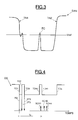
- the value of the delay Tr can be, in some applications, taken equal to zero, it is particularly advantageous to choose it non-zero, to take account of possible distortions of the analog SAN signal, as shown schematically in figure 3.
- a transition TN1 of the signal analog SAN corresponding to an actual coding of a binary information, can result in a first crossing of the voltage Vref followed by a second close crossing in the other direction of this transition Vref, then a third crossing in the opposite direction.
- the SAN signal can present, between two transitions TN1 and TN2, a parasitic peak PC of which the level may be above the reference voltage Vref.
- transition TN1 of the analog signal SAN results in three transitions TD1, TD2 and TD3 close to the DS signal while the parasitic peak PC results in two parasitic transitions TD40 and TD41 of the signal DS.
- Tr for example equal to a quarter of the transmission period T.
- first counter count value the value 5 if the counter counts from 1 to 10.
- the means of selection 2 receiving the detection signals ST2 and ST3 do not deliver not, in response to these signals, a selection signal allowing reset counter 30.
- the means of selection 2 receives on the one hand the detection signal ST and on the other hand part compares the current value of the counter with this second value count to not deliver a selection signal allowing reset this counter, only if the current value of the counter is greater than or equal to this second count value.
- sampling signal SCH1 delivered by the sampling control means at the end of the delay Tr after a detected transition TD1, leads to sampling of the PC parasitic peak of the SAN signal (TD40 transitions and TD41 of the DS signal).
- the means 31 can compare the current value of the counter not only at the first count value of the counter corresponding to the time delay Tr, but to at least one other value counting, greater than the first, so as to deliver at least one other sampling control signal SCH3, SCH4.
- the three sample values (for example) corresponding to the three signals SCH1, SCH3 and SCH4, will then be processed by logic majority allowing elimination of the sampling value PC pic wrong.
- the invention therefore makes it possible to produce a device very simple digital sampling control leading to a sampling always well aligned with the signal transitions, and even if the actual frequency of information transmission binary is subject to variations.
Landscapes
- Engineering & Computer Science (AREA)
- Computer Networks & Wireless Communication (AREA)
- Signal Processing (AREA)
- Physics & Mathematics (AREA)
- Spectroscopy & Molecular Physics (AREA)
- Synchronisation In Digital Transmission Systems (AREA)
- Dc Digital Transmission (AREA)
Abstract
Description
L'invention concerne l'échantillonnage d'un signal comportant une succession de transitions de niveau représentatives d'un codage bi-phase d'informations binaires.The invention relates to the sampling of a signal. comprising a succession of representative level transitions bi-phase coding of binary information.
L'invention s'applique avantageusement mais non limitativement à l'échantillonnage d'un signal vidéo en vue d'en extraire les informations numériques qu'il contient.The invention is advantageously but not limited to sampling a video signal in order to extract the digital information it contains.
Au sens de la présente invention, un codage bi-phase est un codage dont certaines au moins des informations binaires sont codées au moyen d'impulsions dont la durée d'impulsion est égale à la période de transmission de ces informations binaires, et qui présentent une inversion de polarité (transition) au milieu de ladite durée d'impulsion c'est-à-dire au milieu de l'information binaire transmise.Within the meaning of the present invention, a two-phase coding is a coding of which at least some of the binary information is coded using pulses whose pulse duration is equal to the period transmission of this binary information, and which have a reverse polarity (transition) in the middle of said pulse duration that is to say in the middle of the binary information transmitted.
Plus précisément, on peut citer à cet égard le code connu par l'homme du métier sous la dénomination "code Manchester" qui génère des transitions pour chaque élément d'information binaire, quelle que soit la séquence émise. Un "1" logique dans ce code est codé en une impulsion rectangulaire dont la durée est égale à la période de transmission, avec inversion de polarité au milieu du bit, la première moitié étant de signe positif. Un "0" logique est codé en une impulsion de durée identique mais de polarité opposée.More specifically, the code known by a person skilled in the art under the name "Manchester code" which generates transitions for each binary piece of information, whatever either the sequence transmitted. A logical "1" in this code is coded in a rectangular pulse whose duration is equal to the period of transmission, with reverse polarity in the middle of the bit, the first half being of positive sign. A logical "0" is coded in one pulse of identical duration but of opposite polarity.
Un autre code dit "bi-phase" est connu par l'homme du métier sous la dénomination "code de Miller". Selon ce code, un "1" logique est codé en utilisant une impulsion du type Manchester, c'est-à-dire une impulsion rectangulaire avec inversion de polarité au milieu du bit tandis qu'un "0" logique est codé en utilisant une impulsion rectangulaire sans changement de polarité. La polarité des impulsions correspondant à l'émission d'un "1" logique est choisie de façon à garantir une continuité avec l'impulsion précédente. Quant à la polarité des impulsions correspondant à l'émission d'un "0" logique, elle assure une continuité (non-transition) après un "1" logique, mais elle est inversée après un "0" précédent. Aussi, dans ce code, le signal contient une transition au plus toutes les deux durées bit, ce qui assure suffisamment de transitions pour la récupération du flot de données.Another code known as "bi-phase" is known to those skilled in the art under the name "Miller code". According to this code, a logical "1" is coded using a Manchester type pulse, i.e. a rectangular pulse with reverse polarity in the middle of the bit while a logical "0" is coded using a pulse rectangular without change of polarity. Pulse polarity corresponding to the emission of a logical "1" is chosen so as to guarantee continuity with the previous impulse. About the polarity of the pulses corresponding to the emission of a logic "0", it ensures continuity (non-transition) after a logical "1", but it is inverted after a previous "0". Also, in this code, the signal contains a transition at most every two bit durations, which ensures enough transitions to recover the data stream.
On connaít actuellement plusieurs méthodes pour échantillonner un tel signal.We currently know several methods for sample such a signal.
Une première méthode consiste à utiliser un système analogique s'appuyant sur un asservissement de phase et de fréquence, utilisant une boucle à verrouillage de phase, ce qui permet l'obtention d'un signal d'horloge qui est asservi sur la fréquence de transmission des données et qui est en phase avec les transitions de ces mêmes données. Cependant, cette méthode présente l'inconvénient d'utiliser une boucle à verrouillage de phase, qui est un système analogique, difficile à gérer et d'utilisation relativement coûteuse.A first method is to use a system analog based on a phase and frequency servo, using a phase locked loop, which allows obtaining a clock signal which is slaved to the transmission frequency data and that is in step with the transitions of these same data. However, this method has the disadvantage of using a phase locked loop, which is an analog system, difficult to manage and relatively expensive to use.
Une deuxième méthode consiste à utiliser un système réalisant dans une première étape la conversion analogique/numérique des données puis, dans un deuxième temps, le traitement de ses échantillons par un ou des algorithmes plus ou moins complexes de traitement du signal. Cette solution, si elle satisfait pleinement le critère de reproductibilité par son caractère fondamentalement numérique, ne permet par contre pas vraiment l'obtention d'une solution réellement économiquement intéressante, notamment lorsqu'elle est destinée à être intégrée dans des systèmes produits industriellement en grande quantité.A second method is to use a system performing in a first step the analog / digital conversion data then, secondly, the processing of its samples by one or more or less complex algorithms of signal processing. This solution, if it fully satisfies the reproducibility criterion by its fundamentally character digital, does not really allow obtaining a really economical solution, in particular when it is intended to be integrated into product systems industrially in large quantities.
L'invention vise à apporter une solution à ce problème et à proposer un dispositif de commande d'échantillonnage, totalement numérique, n'utilisant donc pas de composant analogique du type boucle à verrouillage de phase, très simple à réaliser à un coût industriellement économique.The invention aims to provide a solution to this problem and to offer a sampling control device, totally digital, therefore using no analog component of the type phase locked loop, very simple to perform at a cost industrially economic.
L'invention propose donc un dispositif de commande de l'échantillonnage d'un signal comportant une succession de transitions de niveau représentatives d'un codage bi-phase d'informations binaires transmises par ce signal selon une fréquence de transmission prédéterminée (par exemple 2,5 MHz).The invention therefore provides a device for controlling sampling a signal comprising a succession of transitions of levels representative of a bi-phase coding of binary information transmitted by this signal at a transmission frequency predetermined (for example 2.5 MHz).
Selon une caractéristique générale de l'invention, ce dispositif comprend
- des moyens de génération d'un signal d'horloge dit "de comptage" dont la fréquence est inférieure ou égale à n fois le double de la fréquence de transmission (par exemple 48 MHz pour n=10),
- des moyens de détection pour détecter les transitions du signal à ladite fréquence de comptage et délivrer des signaux de détection correspondants,
- des moyens de sélection pour recevoir chaque signal de détection et délivrer ou non un signal de sélection en fonction de la satisfaction ou non d'un critère de sélection prédéterminé, et
- des moyens de commande d'échantillonnage comportant des moyens de division de fréquence par n, recevant le signal d'horloge de comptage, ces moyens de commande d'échantillonnage étant aptes, à la réception de chaque signal de sélection, à délivrer un premier signal de commande d'échantillonnage après un retard temporel prédéterminé, inférieur à la moitié de la période de transmission des informations binaires (afin de ne pas masquer des transitions futures) et à délivrer, en l'absence de tout nouveau signal de sélection au cours d'une durée d'espacement égale à n fois la période de comptage, un deuxième signal de commande d'échantillonnage temporellement espacé du premier signal de commande d'échantillonnage de cette durée d'espacement.
- means for generating a so-called "counting" clock signal whose frequency is less than or equal to n times twice the transmission frequency (for example 48 MHz for n = 10),
- detection means for detecting the transitions of the signal at said counting frequency and delivering corresponding detection signals,
- selection means for receiving each detection signal and whether or not to issue a selection signal as a function of the satisfaction or not of a predetermined selection criterion, and
- sampling control means comprising frequency division means by n, receiving the counting clock signal, these sampling control means being capable, on reception of each selection signal, of delivering a first signal sampling command after a predetermined time delay, less than half the period of transmission of binary information (so as not to mask future transitions) and to deliver, in the absence of any new selection signal during d a spacing duration equal to n times the counting period, a second sampling control signal temporally spaced from the first sampling control signal by this spacing duration.
Dans certaines applications dans lesquelles le signal porteur des données (informations binaires) n'a pas subi de distorsions jugées importantes, on peut ajuster le retard temporel à une valeur très faible, voire quasi nulle ou nulle. De même, on peut dans ce type d'application prévoir de délivrer un signal de sélection pour chaque signal de détection. En d'autres termes, on prendra alors en compte toutes les transitions détectées du signal.In certain applications in which the carrier signal data (binary information) has not been judged to be distorted important, we can adjust the time delay to a very low value, or even almost zero or zero. Similarly, we can in this type application plan to issue a selection signal for each detection signal. In other words, we will then take into account all detected signal transitions.
Ceci étant, dans de nombreuses applications, le signal peut avoir subi des distorsions importantes lors de sa transmission, notamment lors d'une transmission hertzienne ou par câble, pouvant se combiner avec des phénomènes d'atténuation, de recombinaison d'échos de ce signal, d'ajout de perturbations externes ou de distorsions non linéaires en fréquence. Aussi, afin d'effectuer en quelque sorte un filtrage de ce bruit et des distorsions de données, on ajustera le retard temporel à une valeur prédéterminée. De même, afin d'éviter de réinitialiser le diviseur de fréquence sur des transitions trop proches les unes des autres et qui ne représentent pas des transitions issues du codage proprement dit des informations binaires, mais qui sont la conséquence de ces distorsions, on ne prendra avantageusement pas en compte des transitions ultérieures détectées mais trop proches d'une transition précédemment détectée.However, in many applications, the signal can have suffered significant distortions during transmission, in particular during a hertzian transmission or by cable, being able to combine with attenuation, recombination phenomena echoes of this signal, addition of external disturbances or non-linear frequency distortions. Also, in order to perform in sort of filtering out that noise and data distortions, we will adjust the time delay to a predetermined value. Likewise, so avoid resetting the frequency divider on transitions too close to each other and which do not represent transitions from the actual coding of binary information, but which are the consequence of these distortions, we will not take advantageously not taking into account subsequent transitions detected but too close to a previously detected transition.
Ainsi, en d'autres termes, l'invention prévoit d'utiliser un diviseur de fréquence recevant une fréquence fixe suffisamment élevée, ce diviseur étant réarmé à chaque transition de la donnée reçue (compte tenu éventuellement du filtrage évoqué ci-dessus) afin de délivrer au moins une impulsion d'horloge servant à échantillonner cette donnée, c'est-à-dire le signal porteur.Thus, in other words, the invention provides for using a frequency divider receiving a fixed frequency sufficiently high, this divider being reset at each transition of the data received (possibly taking into account the filtering mentioned above) in order to deliver at least one clock pulse used for sampling this data, that is to say the carrier signal.
Alors que la fréquence du signal de comptage doit être inférieure à n fois le double de la fréquence de transmission, la limite inférieure de cette fréquence de comptage doit être ajustée compte tenu de la précision souhaitée pour l'application envisagée. Pour une précision maximale on choisira, pour n fixé, une fréquence du signal de comptage inférieure à n fois le double de la fréquence de transmission et supérieure à n-1 fois le double de la fréquence de transmission, et on choisira de préférence une fréquence située au voisinage inférieur de la limite supérieure de cet intervalle.While the frequency of the count signal must be less than n times twice the transmission frequency, the limit lower of this counting frequency must be adjusted account given the precision desired for the intended application. For a maximum precision we will choose, for n fixed, a signal frequency counting less than n times twice the frequency of transmission and greater than n-1 times twice the frequency of transmission, and preferably choose a frequency located at lower vicinity of the upper limit of this interval.
Selon un mode de réalisation de l'invention, les moyens de division de fréquence comportent un compteur modulo n, cadencé par le signal d'horloge de comptage, initialisable à une valeur initiale de comptage en présence de chaque signal de sélection. Chaque signal de commande d'échantillonnage est alors délivré à chaque fois que le compteur atteint une première valeur de comptage.According to one embodiment of the invention, the means of frequency division include a modulo n counter, clocked by the counting clock signal, initializable to an initial value of counting in the presence of each selection signal. Each signal from sampling order is then issued each time the counter reaches a first count value.
Le retard temporel est alors égal à un premier nombre prédéterminé de périodes du signal de comptage, la différence entre la première valeur de comptage et la valeur initiale de comptage correspondant à ce premier nombre prédéterminé de périodes.The time delay is then equal to a first number predetermined periods of the count signal, the difference between the first count value and initial count value corresponding to this first predetermined number of periods.
Selon un mode de réalisation de l'invention, les moyens de sélection comportent des moyens aptes à comptabiliser la durée séparant deux transitions détectées consécutives, le critère de sélection consistant à vérifier que cette durée est supérieure ou égale à une durée de latence prédéterminée. Cette durée de latence est avantageusement égale à un deuxième nombre prédéterminé de périodes du signal de comptage. Les moyens de sélection comportent alors des moyens de comparaison aptes à comparer la valeur courante du compteur avec une deuxième valeur de comptage prédéterminée dont la différence avec la valeur initiale de comptage correspond à ce deuxième nombre prédéterminé de périodes.According to one embodiment of the invention, the means of selection include means capable of recording the duration separating two consecutive detected transitions, the criterion of selection consisting in verifying that this duration is greater than or equal to a predetermined latency period. This latency is advantageously equal to a second predetermined number of count signal periods. The selection means include then comparison means able to compare the current value of the counter with a second predetermined count value whose difference with the initial count value corresponds to this second predetermined number of periods.
Afin d'optimiser encore les performances du système, et d'être notamment moins sensible à des pics parasites se situant entre deux transitions utiles du signal et pouvant conduire à des valeurs d'échantillonnage fausses, les moyens de commande d'échantillonnage délivrent avantageusement plusieurs signaux de commande d'échantillonnage de façon à effectuer un suréchantillonnage du signal et à permettre la mise en oeuvre d'une logique majoritaire en aval pour une meilleure détermination de la valeur exacte du signal porteur.To further optimize system performance, and to be in particular less sensitive to parasitic peaks lying between two useful signal transitions which can lead to values false sampling, sampling control means advantageously deliver several sampling control signals so as to oversample the signal and to allow the implementation of a majority logic downstream for a better determination of the exact value of the carrier signal.
D'autres avantages et caractéristiques de l'invention apparaítront à l'examen de la description détaillée d'un mode de réalisation nullement limitatif, et des dessins annexés sur lesquels :
- la figure 1 est un synoptique schématique d'un dispositif de commande d'échantillonnage selon l'invention,
- la figure 2 illustre un mode de mise en oeuvre de l'invention appliqué à un codage bi-phase du type Manchester, et
- les figures 3 et 4 illustrent une autre mise en oeuvre de l'invention permettant une meilleure immunité vis-à-vis des distorsions éventuelles du signal porteur.
- FIG. 1 is a schematic block diagram of a sampling control device according to the invention,
- FIG. 2 illustrates an embodiment of the invention applied to bi-phase coding of the Manchester type, and
- Figures 3 and 4 illustrate another implementation of the invention allowing better immunity to possible distortions of the carrier signal.
Sur la figure 1, un signal analogique SAN, par exemple un signal vidéo issu d'un magnétoscope, et contenant des informations numériques codées par un codage bi-phase, est délivré à une première entrée d'un comparateur CMP1 dont l'autre entrée reçoit une valeur de référence choisie Vref. La sortie de ce comparateur CMP1 délivre un signal porteur DS composé d'une succession de transitions de niveau représentatives du codage bi-phase des informations binaires.In FIG. 1, an analog signal SAN, for example a video signal from a VCR containing information digital coded by a bi-phase coding, is delivered to a first input of a comparator CMP1 whose other input receives a value of chosen reference Vref. The output of this CMP1 comparator delivers a DS carrier signal composed of a succession of level transitions representative of the bi-phase coding of binary information.
Un exemple d'un tel signal DS est illustré sur la partie haute de la figure 2 qui illustre un codage bi-phase du type Manchester.An example of such a DS signal is illustrated on the upper part of FIG. 2 which illustrates a bi-phase coding of the Manchester type.
Plus précisément, les informations binaires sont transmises périodiquement par le signal selon une fréquence de transmission F correspondant à une période de transmission T. A titre indicatif, la fréquence de transmission peut être égale à 2,5 MHz correspondant à une période T de 0,4 µs (durée de transmission de l'information binaire).More specifically, binary information is transmitted periodically by the signal at a transmission frequency F corresponding to a transmission period T. As an indication, the transmission frequency can be equal to 2.5 MHz corresponding to a period T of 0.4 µs (duration of information transmission binary).
Comme illustré sur cette figure 2, un "1" logique dans ce code est codé en une impulsion rectangulaire de durée T avec inversion de polarité au milieu de l'information binaire, la première moitié étant de signe positif. Un "0" est codé en une impulsion identique mais de polarité opposée. On remarque donc que les transitions TD du signal DS sont espacées de la moitié T/2 de la période de transmission T, sauf lorsque deux informations binaires de valeur logiques différentes se succèdent. Dans ce cas, les deux transitions du signal DS sont espacées de la période de transmission T.As illustrated in this figure 2, a logical "1" in this code is coded in a rectangular pulse of duration T with reverse polarity in the middle of binary information, the first half being of positive sign. A "0" is coded in one pulse identical but of opposite polarity. We therefore notice that the TD transitions of the DS signal are spaced half T / 2 from the transmission period T, except when two binary items of different logical values follow one another. In this case, both DS signal transitions are spaced from the transmission period T.
Si l'on revient maintenant plus particulièrement à la figure 1,
on voit que le dispositif de commande d'échantillonnage 1 selon
l'invention comporte des moyens de génération 4, par exemple un
quartz, apte à générer un signal d'horloge dit "de comptage", CKM,
dont la fréquence est choisie inférieure ou égale à n fois le double de
la fréquence de transmission F. En pratique, n est un nombre entier
suffisamment élevé, au moins supérieur ou égal à 3 et par exemple
égal à 10. Dans le cas où la fréquence de transmission des
informations binaires est égale à 2,5 MHz, correspondant à une
fréquence maximale des transitions de 5 MHz, on choisira
avantageusement pour le signal CKM une fréquence de comptage de 48
MHz.If we now return more particularly to Figure 1,
we see that the
Le dispositif 1 comporte également des moyens de détection
10 pour détecter les transitions TD du signal DS à ladite fréquence de
comptage et délivrer des signaux de détection correspondants ST. The
Plus précisément, comme illustré de façon très schématique
sur cette figure 1, les moyens de détection de transition 10 comportent
une succession de trois bascules de type D respectivement référencées
100, 101 et 102, disposées en cascade et toutes commandées par le
signal d'horloge CKM. L'entrée de la première bascule 100 reçoit le
signal porteur DS. Les sorties des deux dernières bascules 101 et 102
sont reliées à une porte logique OU exclusif référencée 103 dont la
sortie délivre le signal de détection ST.More specifically, as illustrated very schematically
in this figure 1, the transition detection means 10 comprise
a succession of three D-type flip-flops respectively referenced
100, 101 and 102, arranged in cascade and all controlled by the
CKM clock signal. The input of the first flip-
Un circuit logique 2, dont on reviendra plus en détail ci-après sur la fonctionnalité, et réalisable de façon classique à partir de portes logiques, forme des moyens de sélection 2. Ces moyens de sélection reçoivent en entrée chaque signal de détection ST délivré par les moyens de détection 10 et délivrent ou non, en fonction d'un critère de sélection prédéterminé, un signal de sélection RS. Bien entendu, l'homme du métier aura compris que le signal de sélection correspond en fait à une valeur logique prédéterminée, par exemple 1, du signal logique délivré par les moyens de sélection 2.Logic circuit 2, which will be discussed in more detail below on functionality, and achievable in a conventional way from doors logic, form of selection means 2. These selection means receive as input each ST detection signal delivered by the detection means 10 and deliver or not, according to a criterion of predetermined selection, an RS selection signal. Of course, a person skilled in the art will understand that the selection signal corresponds actually at a predetermined logic value, say 1, of the signal logic delivered by the selection means 2.
Des moyens de commande d'échantillonnage 3 comportent
notamment un compteur modulo n (en l'espèce modulo 10) référencé
30 et cadencé par le signal d'horloge de comptage CKM. La sortie de
ce compteur 30, c'est-à-dire sa valeur courante de comptage est prise
en compte d'une part par les moyens de sélection 2 d'une manière
détaillée ci-après et, d'autre part, par des moyens logiques 31, de
réalisation classique. Ces moyens 31 sont aptes à comparer la valeur
courante de comptage SC à une première valeur de comptage
prédéterminée correspondant à un premier nombre de périodes du
signal d'horloge CKM, et par conséquent à un retard temporel Tr
prédéterminé pour, lorsque la valeur courante du compteur atteint ce
premier nombre, délivrer un signal de commande d'échantillonnage
SCH à une bascule d'échantillonnage ECH permettant d'échantillonner
le signal DS.Sampling control means 3 include
in particular a modulo n counter (in this case modulo 10) referenced
30 and clocked by the counting clock signal CKM. The exit of
this
On se réfère maintenant plus particulièrement aux figures 2 à 4 pour décrire plus en détail un mode de mise en oeuvre de la commande d'échantillonnage selon l'invention.Reference is now made more particularly to FIGS. 2 to 4 to describe in more detail an embodiment of the sampling control according to the invention.
On suppose sur la figure 2 que toutes les transitions détectées
TD du signal DS sont effectivement prises en compte par les moyens
de commande d'échantillonnage. En d'autres termes, on suppose ici
que toute transition détectée est une transition sélectionnée donnant
lieu à l'émission par les moyens de sélection d'un signal de sélection
RS. A la réception de chaque signal de sélection RS, le compteur 30
est initialisé à une valeur initiale de comptage, par exemple 1, puis
compte au rythme des fronts montants du signal d'horloge de comptage
CKM. Au bout d'un premier nombre prédéterminé de périodes de ce
signal de comptage, c'est-à-dire lorsque le compteur a atteint une
première valeur de comptage, par exemple la valeur 5, correspondant
au retard temporel Tr qui est inférieur à la moitié T/2 de la période de
transmission T (afin de ne pas masquer une prochaine transition TD
telle que dessinée sur la figure 2), un signal d'échantillonnage SCH est
délivré.It is assumed in FIG. 2 that all the detected transitions
TD of the DS signal are effectively taken into account by the means
sampling control. In other words, we assume here
that any transition detected is a selected transition giving
place on the transmission by the selection means of a selection signal
RS. On receipt of each RS selection signal, the
Par ailleurs, lorsque le compteur 30 atteint sa valeur finale de
comptage, en l'espèce 10, il est réinitialisé à sa valeur initiale. Dans
ces conditions, comme illustré sur la figure 2, après qu'un premier
signal d'échantillonnage SCH1 ait été délivré à l'issue du retard
temporel Tr après la détection d'une transition, un deuxième signal
d'échantillonnage SCH2 sera automatiquement délivré lorsque le
compteur 30 aura de nouveau atteint sa première valeur de comptage,
c'est-à-dire à l'issue de la durée Tm égale à n fois la période de
comptage, et ce bien qu'aucune autre transition n'ait été détectée. Ceci
permet donc un échantillonnage correct du signal DS lorsque deux
informations binaires de valeurs logiques différentes se succèdent.Furthermore, when the
Bien que la valeur du retard Tr puisse être, dans certaines applications, prise égale à zéro, il est particulièrement avantageux de la choisir non nulle, pour tenir compte des distorsions éventuellement importantes du signal analogique SAN, tel qu'illustré schématiquement sur la figure 3.Although the value of the delay Tr can be, in some applications, taken equal to zero, it is particularly advantageous to choose it non-zero, to take account of possible distortions of the analog SAN signal, as shown schematically in figure 3.
Sur cette figure 3, on voit qu'une transition TN1 du signal analogique SAN, correspondant à un codage proprement dit d'une information binaire, peut se traduire par un premier franchissement de la tension Vref suivie d'un deuxième franchissement rapproché dans l'autre sens de cette transition Vref, puis d'un troisième franchissement dans le sens opposé. De même, le signal SAN peut présenter, entre deux transitions TN1 et TN2, un pic parasite PC dont le niveau peut se situer au-dessus de la tension de référence Vref.In this figure 3, we see that a transition TN1 of the signal analog SAN, corresponding to an actual coding of a binary information, can result in a first crossing of the voltage Vref followed by a second close crossing in the other direction of this transition Vref, then a third crossing in the opposite direction. Similarly, the SAN signal can present, between two transitions TN1 and TN2, a parasitic peak PC of which the level may be above the reference voltage Vref.
On voit donc, comme illustré sur la figure 4, que la transition TN1 du signal analogique SAN se traduit par trois transitions rapprochées TD1, TD2 et TD3 du signal DS tandis que le pic parasite PC se traduit par deux transitions parasites TD40 et TD41 du signal DS.We therefore see, as illustrated in Figure 4, that the transition TN1 of the analog signal SAN results in three transitions TD1, TD2 and TD3 close to the DS signal while the parasitic peak PC results in two parasitic transitions TD40 and TD41 of the signal DS.
Afin de minimiser le risque d'échantillonner le signal DS sur des nivaux parasites du signal DS, c'est-à-dire pour notamment ne pas risquer d'échantillonner le signal DS entre les transitions TD2 et TD3, on choisira un retard temporel Tr par exemple égal au quart de la période de transmission T. En d'autres termes, on choisira comme première valeur de comptage du compteur, la valeur 5 si le compteur compte de 1 à 10.To minimize the risk of sampling the DS signal on parasitic levels of the DS signal, that is to say in particular not risk sampling the DS signal between the TD2 and TD3 transitions, we will choose a time delay Tr for example equal to a quarter of the transmission period T. In other words, we will choose as first counter count value, the value 5 if the counter counts from 1 to 10.
De même, il est préférable de ne pas réinitialiser le compteur
sur les transitions parasites TD2 et TD3. Aussi, les moyens de
sélection 2, recevant les signaux de détection ST2 et ST3 ne délivrent
pas, en réponse à ces signaux, un signal de sélection permettant de
réinitialiser le compteur 30. En pratique, on fixe un deuxième nombre
prédéterminé de périodes du signal de comptage CKM correspondant à
une deuxième valeur de comptage du compteur. Le circuit logique de
sélection 2 reçoit alors d'une part le signal de détection ST et d'autre
part compare la valeur courante du compteur à cette deuxième valeur
de comptage pour ne délivrer un signal de sélection permettant de
réinitialiser ce compteur, que si la valeur courante du compteur est
supérieure ou égale à cette deuxième valeur de comptage.Similarly, it is better not to reset the counter
on the parasitic transitions TD2 and TD3. Also, the means of
selection 2, receiving the detection signals ST2 and ST3 do not deliver
not, in response to these signals, a selection signal allowing
Enfin, il est possible que le signal d'échantillonnage SCH1, délivré par les moyens de commande d'échantillonnage à l'issue du retard Tr après une transition détectée TD1, conduise à l'échantillonnage du pic parasite PC du signal SAN (transitions TD40 et TD41 du signal DS).Finally, it is possible that the sampling signal SCH1, delivered by the sampling control means at the end of the delay Tr after a detected transition TD1, leads to sampling of the PC parasitic peak of the SAN signal (TD40 transitions and TD41 of the DS signal).
Pour remédier à cet inconvénient, on peut prévoir un
suréchantillonnage du signal DS entre les transistors TD4 et TD5. En
d'autres termes, les moyens 31 peuvent comparer la valeur courante du
compteur non seulement à la première valeur de comptage du compteur
correspondant au retard temporel Tr, mais à au moins une autre valeur
de comptage, supérieure à la première, de façon à délivrer au moins un
autre signal de commande d'échantillonnage SCH3, SCH4. Les trois
valeurs d'échantillonnage (par exemple) correspondant aux trois
signaux SCH1, SCH3 et SCH4, seront ensuite traitées par une logique
majoritaire permettant une élimination de la valeur d'échantillonnage
fausse du pic PC.To overcome this drawback, a
oversampling of the DS signal between the transistors TD4 and TD5. In
in other words, the
L'invention permet donc la réalisation d'un dispositif numérique très simple de commande d'échantillonnage conduisant à un échantillonnage toujours bien aligné avec les transitions du signal, et ce même si la fréquence réelle de transmission des informations binaires est sujette à des variations.The invention therefore makes it possible to produce a device very simple digital sampling control leading to a sampling always well aligned with the signal transitions, and even if the actual frequency of information transmission binary is subject to variations.
Claims (8)
Applications Claiming Priority (2)
| Application Number | Priority Date | Filing Date | Title |
|---|---|---|---|
| FR9711864A FR2768881B1 (en) | 1997-09-24 | 1997-09-24 | DEVICE FOR CONTROLLING THE SAMPLING OF A SIGNAL CARRYING BINARY INFORMATION ENCODED ACCORDING TO TWO-PHASE CODING |
| FR9711864 | 1997-09-24 |
Publications (2)
| Publication Number | Publication Date |
|---|---|
| EP0905946A1 true EP0905946A1 (en) | 1999-03-31 |
| EP0905946B1 EP0905946B1 (en) | 2005-11-09 |
Family
ID=9511413
Family Applications (1)
| Application Number | Title | Priority Date | Filing Date |
|---|---|---|---|
| EP98402317A Expired - Lifetime EP0905946B1 (en) | 1997-09-24 | 1998-09-21 | Control of the sampling of biphase signals |
Country Status (4)
| Country | Link |
|---|---|
| US (1) | US6097322A (en) |
| EP (1) | EP0905946B1 (en) |
| DE (1) | DE69832243D1 (en) |
| FR (1) | FR2768881B1 (en) |
Families Citing this family (4)
| Publication number | Priority date | Publication date | Assignee | Title |
|---|---|---|---|---|
| US6772021B1 (en) * | 1998-11-16 | 2004-08-03 | Creative Technology Ltd. | Digital audio data receiver without synchronized clock generator |
| DE10163702A1 (en) * | 2001-12-21 | 2003-07-10 | Infineon Technologies Ag | Circuit for recovering a clock signal from a digitally coded signal |
| DE102005021193A1 (en) * | 2005-05-03 | 2006-11-09 | Endress + Hauser Gmbh + Co. Kg | Circuit arrangement and method for signal conditioning of a digital signal |
| TWI732562B (en) * | 2020-05-25 | 2021-07-01 | 創惟科技股份有限公司 | Method of reading data and data-reading device |
Citations (3)
| Publication number | Priority date | Publication date | Assignee | Title |
|---|---|---|---|---|
| US5491713A (en) * | 1993-04-28 | 1996-02-13 | Hughes Aircraft Company | Minimized oversampling Manchester decoder |
| EP0707391A2 (en) * | 1994-10-14 | 1996-04-17 | International Business Machines Corporation | Flash FM infrared modem |
| EP0773653A2 (en) * | 1995-11-13 | 1997-05-14 | Texas Instruments Incorporated | Method and apparatus for decoding Manchester-encoded data |
-
1997
- 1997-09-24 FR FR9711864A patent/FR2768881B1/en not_active Expired - Fee Related
-
1998
- 1998-09-21 EP EP98402317A patent/EP0905946B1/en not_active Expired - Lifetime
- 1998-09-21 DE DE69832243T patent/DE69832243D1/en not_active Expired - Lifetime
- 1998-09-23 US US09/159,319 patent/US6097322A/en not_active Expired - Fee Related
Patent Citations (3)
| Publication number | Priority date | Publication date | Assignee | Title |
|---|---|---|---|---|
| US5491713A (en) * | 1993-04-28 | 1996-02-13 | Hughes Aircraft Company | Minimized oversampling Manchester decoder |
| EP0707391A2 (en) * | 1994-10-14 | 1996-04-17 | International Business Machines Corporation | Flash FM infrared modem |
| EP0773653A2 (en) * | 1995-11-13 | 1997-05-14 | Texas Instruments Incorporated | Method and apparatus for decoding Manchester-encoded data |
Also Published As
| Publication number | Publication date |
|---|---|
| EP0905946B1 (en) | 2005-11-09 |
| US6097322A (en) | 2000-08-01 |
| FR2768881B1 (en) | 2002-01-11 |
| FR2768881A1 (en) | 1999-03-26 |
| DE69832243D1 (en) | 2005-12-15 |
Similar Documents
| Publication | Publication Date | Title |
|---|---|---|
| EP0419337B1 (en) | Digital signal encoding method, encoder and decoder for carrying out the method, regeneration method and regenerator therefore | |
| EP0013990B1 (en) | Serial binary information transmission method and devices for implementing the method | |
| FR2880482A1 (en) | DEVICE FOR CONVERTING A SIGNAL TRANSMITTED TO A DIGITAL SIGNAL | |
| FR2498032A1 (en) | BIT SYNCHRONIZER FOR DIGITAL SIGNALS | |
| EP0421897B1 (en) | Device for extracting digital data from a video signal | |
| FR2509890A1 (en) | DATA READING APPARATUS FOR DATA TRANSMISSION | |
| EP0932283B1 (en) | BPSK demodulator for a PCM signal | |
| FR2736231A1 (en) | DIGITAL COMMUNICATION SYSTEM COMPRISING A RECEIVER HAVING A RHYTHM RECOVERY DEVICE | |
| FR2497958A1 (en) | DEVICE FOR DETERMINING THE PULSE ARRIVAL TIME, USE IN DISTANCE MEASURING EQUIPMENT AND MEASURING EQUIPMENT COMPRISING SUCH A DEVICE | |
| EP0730377A1 (en) | Circuit for processing an asynchronous signal containing a periodical synchronisation burst | |
| EP0023852A1 (en) | Method and device for adjusting the phase of a local clock | |
| EP0905946B1 (en) | Control of the sampling of biphase signals | |
| EP0018242A1 (en) | Method and device for stochastic demodulation of phase-shift keyed signals working in time division on several channels | |
| EP0012880B1 (en) | Method of decoding phase-encoded, frequency-modulation encoded and modified-frequency modulation encoded binary data | |
| EP1101316B1 (en) | Clock recovery method in digital signal sampling | |
| FR2707128A1 (en) | A single word detection device modulated in BPSK adapted to an analog modem operating in TMDA mode and detection method implemented in such a device. | |
| EP1131772B1 (en) | Digital transmission method | |
| CA2057942C (en) | Receiver for processing signals received over diversity channels | |
| EP0541408B1 (en) | Method and device for controlling the mode of functioning of a digital phase lock loop | |
| EP0184953B1 (en) | Method and device for digital information transmission using differential frequency shift keying | |
| EP0109332B1 (en) | Arrangement for receiving radio messages consisting of biphase-type signals | |
| EP1296469B1 (en) | Decision device for a modulated electrical signal | |
| EP1536566B1 (en) | Electronic circuit for decoding of an asynchronous biphase signal, corresponding method and corresponding control device. | |
| CA1287126C (en) | Method and device for detecting false lockings of the reference signal onthe signal to be demodulated during a coherent digital demodulation | |
| EP0237408B1 (en) | Method and device for asynchronous clock recovery for digital transmission systems |
Legal Events
| Date | Code | Title | Description |
|---|---|---|---|
| PUAI | Public reference made under article 153(3) epc to a published international application that has entered the european phase |
Free format text: ORIGINAL CODE: 0009012 |
|
| AK | Designated contracting states |
Kind code of ref document: A1 Designated state(s): DE FR GB IT |
|
| AX | Request for extension of the european patent |
Free format text: AL;LT;LV;MK;RO;SI |
|
| 17P | Request for examination filed |
Effective date: 19990414 |
|
| AKX | Designation fees paid |
Free format text: DE FR GB IT |
|
| RAP1 | Party data changed (applicant data changed or rights of an application transferred) |
Owner name: STMICROELECTRONICS S.A. |
|
| 17Q | First examination report despatched |
Effective date: 20040405 |
|
| GRAP | Despatch of communication of intention to grant a patent |
Free format text: ORIGINAL CODE: EPIDOSNIGR1 |
|
| GRAS | Grant fee paid |
Free format text: ORIGINAL CODE: EPIDOSNIGR3 |
|
| GRAA | (expected) grant |
Free format text: ORIGINAL CODE: 0009210 |
|
| AK | Designated contracting states |
Kind code of ref document: B1 Designated state(s): DE FR GB IT |
|
| PG25 | Lapsed in a contracting state [announced via postgrant information from national office to epo] |
Ref country code: IT Free format text: LAPSE BECAUSE OF FAILURE TO SUBMIT A TRANSLATION OF THE DESCRIPTION OR TO PAY THE FEE WITHIN THE PRESCRIBED TIME-LIMIT;WARNING: LAPSES OF ITALIAN PATENTS WITH EFFECTIVE DATE BEFORE 2007 MAY HAVE OCCURRED AT ANY TIME BEFORE 2007. THE CORRECT EFFECTIVE DATE MAY BE DIFFERENT FROM THE ONE RECORDED. Effective date: 20051109 |
|
| REG | Reference to a national code |
Ref country code: GB Ref legal event code: FG4D Free format text: NOT ENGLISH |
|
| REF | Corresponds to: |
Ref document number: 69832243 Country of ref document: DE Date of ref document: 20051215 Kind code of ref document: P |
|
| PG25 | Lapsed in a contracting state [announced via postgrant information from national office to epo] |
Ref country code: DE Free format text: LAPSE BECAUSE OF FAILURE TO SUBMIT A TRANSLATION OF THE DESCRIPTION OR TO PAY THE FEE WITHIN THE PRESCRIBED TIME-LIMIT Effective date: 20060210 |
|
| GBT | Gb: translation of ep patent filed (gb section 77(6)(a)/1977) |
Effective date: 20060202 |
|
| PLBE | No opposition filed within time limit |
Free format text: ORIGINAL CODE: 0009261 |
|
| STAA | Information on the status of an ep patent application or granted ep patent |
Free format text: STATUS: NO OPPOSITION FILED WITHIN TIME LIMIT |
|
| 26N | No opposition filed |
Effective date: 20060810 |
|
| PGFP | Annual fee paid to national office [announced via postgrant information from national office to epo] |
Ref country code: GB Payment date: 20070830 Year of fee payment: 10 |
|
| PGFP | Annual fee paid to national office [announced via postgrant information from national office to epo] |
Ref country code: FR Payment date: 20070926 Year of fee payment: 10 |
|
| GBPC | Gb: european patent ceased through non-payment of renewal fee |
Effective date: 20080921 |
|
| REG | Reference to a national code |
Ref country code: FR Ref legal event code: ST Effective date: 20090529 |
|
| PG25 | Lapsed in a contracting state [announced via postgrant information from national office to epo] |
Ref country code: FR Free format text: LAPSE BECAUSE OF NON-PAYMENT OF DUE FEES Effective date: 20080930 |
|
| PG25 | Lapsed in a contracting state [announced via postgrant information from national office to epo] |
Ref country code: GB Free format text: LAPSE BECAUSE OF NON-PAYMENT OF DUE FEES Effective date: 20080921 |