EP1309035B1 - Switched antenna - Google Patents
Switched antenna Download PDFInfo
- Publication number
- EP1309035B1 EP1309035B1 EP02292593A EP02292593A EP1309035B1 EP 1309035 B1 EP1309035 B1 EP 1309035B1 EP 02292593 A EP02292593 A EP 02292593A EP 02292593 A EP02292593 A EP 02292593A EP 1309035 B1 EP1309035 B1 EP 1309035B1
- Authority
- EP
- European Patent Office
- Prior art keywords
- slot
- line
- antenna
- supply line
- transition
- Prior art date
- Legal status (The legal status is an assumption and is not a legal conclusion. Google has not performed a legal analysis and makes no representation as to the accuracy of the status listed.)
- Expired - Lifetime
Links
- 230000005540 biological transmission Effects 0.000 claims description 21
- 230000007704 transition Effects 0.000 claims description 17
- 230000008878 coupling Effects 0.000 claims description 7
- 238000010168 coupling process Methods 0.000 claims description 7
- 238000005859 coupling reaction Methods 0.000 claims description 7
- 230000005855 radiation Effects 0.000 description 16
- 230000010287 polarization Effects 0.000 description 8
- 239000000758 substrate Substances 0.000 description 8
- 238000005516 engineering process Methods 0.000 description 6
- 238000005562 fading Methods 0.000 description 5
- 238000000034 method Methods 0.000 description 3
- 230000015556 catabolic process Effects 0.000 description 2
- 238000006731 degradation reaction Methods 0.000 description 2
- 238000002955 isolation Methods 0.000 description 2
- 238000005259 measurement Methods 0.000 description 2
- 238000004088 simulation Methods 0.000 description 2
- 238000005388 cross polarization Methods 0.000 description 1
- 230000008054 signal transmission Effects 0.000 description 1
- 230000001131 transforming effect Effects 0.000 description 1
Images


Classifications
-
- H—ELECTRICITY
- H04—ELECTRIC COMMUNICATION TECHNIQUE
- H04B—TRANSMISSION
- H04B7/00—Radio transmission systems, i.e. using radiation field
- H04B7/02—Diversity systems; Multi-antenna system, i.e. transmission or reception using multiple antennas
-
- H—ELECTRICITY
- H01—ELECTRIC ELEMENTS
- H01Q—ANTENNAS, i.e. RADIO AERIALS
- H01Q3/00—Arrangements for changing or varying the orientation or the shape of the directional pattern of the waves radiated from an antenna or antenna system
- H01Q3/24—Arrangements for changing or varying the orientation or the shape of the directional pattern of the waves radiated from an antenna or antenna system varying the orientation by switching energy from one active radiating element to another, e.g. for beam switching
-
- H—ELECTRICITY
- H01—ELECTRIC ELEMENTS
- H01Q—ANTENNAS, i.e. RADIO AERIALS
- H01Q13/00—Waveguide horns or mouths; Slot antennas; Leaky-waveguide antennas; Equivalent structures causing radiation along the transmission path of a guided wave
- H01Q13/10—Resonant slot antennas
- H01Q13/106—Microstrip slot antennas
-
- H—ELECTRICITY
- H01—ELECTRIC ELEMENTS
- H01Q—ANTENNAS, i.e. RADIO AERIALS
- H01Q21/00—Antenna arrays or systems
- H01Q21/06—Arrays of individually energised antenna units similarly polarised and spaced apart
- H01Q21/08—Arrays of individually energised antenna units similarly polarised and spaced apart the units being spaced along or adjacent to a rectilinear path
Definitions
- the present invention relates to an antenna system for the transmission of electromagnetic signals which can be used in the field of wireless transmissions, especially in the case of transmissions in a closed or semi-closed environment such as domestic environments, gymnasia, television studios, cinemas and theatres, or the like.
- the signals transmitted by the transmitter reach the receiver along a plurality of different paths.
- the phase differences between the various rays having travelled paths of different lengths give rise to an interference pattern likely to cause fading or significant degradation of the signal.
- the location of the fading changes over time depending on changes in the environment such as the presence of new objects or the passage of people.
- This fading due to the multiple paths may lead to significant degradation, in terms of both the quality of the signal received and system performance.
- the technique most often used is a technique with spatial diversity.
- This technique consists inter alia in using a pair of antennas with large spatial coverage such as two antennas of the patch type combined with a switch.
- the two antennas are separated by a length which must be greater than or equal to ⁇ 0 /2 where ⁇ 0 is the wavelength corresponding to the operating frequency of the antenna.
- ⁇ 0 is the wavelength corresponding to the operating frequency of the antenna.
- an antenna of the slot type such as an annular slot supplied by a tangential line/slot transition see for example T Dusseux "Etudes d'antennes fentes annulaires imprimées Applications :Antennes sharinguses cleanse” Thèse de doctorat, elle de Rennes I, 1987.
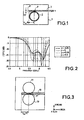
- An antenna of this type is shown in Figure 1 .
- this annular slot 2 is supplied by a line/slot transition which is substantially tangential at the point P.
- the line/slot transition consists of a microstrip line 3 made on the substrate 1, this microstrip line being at a distance y from the point of tangency to the slot 2.
- the length of the microstrip line 3 between its end 3' and the point P is about k ⁇ m /4. where k is an odd integer and ⁇ m the wavelength guided in the microstrip line.
- the characteristic impedance of the microstrip line is chosen so as to provide 50 ohms at the port 1. In this case, the coupling between the slot and the microstrip line is of electromagnetic type.
- Figure 2 also shows the reflection coefficient S11 of an annular slot 2 as a function of the frequency for the various values of y given in Table 1. These curves give the matching of the annular slot to the said values.
- the present invention therefore relates to an antenna system for the transmission of electromagnetic signals using slot-type antennas supplied by a line/slot transition as described above, making it possible to obtain compact antennas with a broad frequency band, and with linear polarization of very high purity.
- the present invention also relates to a novel topology of antennas as described above, making it possible to obtain a compact device with radiation diversity.
- the invention is defined in claim 1.
- the length of each supply line between the component and the point of symmetry is about k ⁇ m /4 where k is an integer and ⁇ m the wavelength guided in the line, so as to restore an electrical short-circuit or open-circuit plane depending on the state of the component in the plane containing the points of symmetry.
- the means for the transmission of electromagnetic waves of the slot antenna type supplied by a line/slot transition consist of a slot of annular or polygonal shape, it being possible for the polygonal shape to be a rectangle or a square or any other known polygonal shape.
- the perimeter of the slot may have a wavelength of about k' ⁇ s where k' is an integer and ⁇ s the wavelength guided in the slot.
- the device further comprises a third supply line connected to a transmission means and electromagnetically coupled to the central electromagnetic wave transmission means by a line/slot transition.
- the component consists of a diode, a transistor, an electronic switch and a microelectromechanical system. Furthermore, the supply lines are produced using microstrip technology or coplanar technology.
- electromagnetic wave transmission means refers to any means capable of transmitting and/or of receiving electromagnetic waves, these means being known by the term "antenna”.
- the antenna system comprises slot-type antennas consisting of two annular slots 10, 11 placed on each side of a microstrip supply line 12 which is tangent at a point P' to the two slots 10 and 11.
- the two annular slots are supplied by a line/slot transition giving magnetic coupling between the supply line (12) and the slots.
- the length of the supply line between its end away from the input port and the point of tangency is about k ⁇ m /4 where k is an odd integer and ⁇ m the wavelength guided by the microstrip line.
- each annular slot 10, 11 is substantially equal to k' ⁇ s where k' is an integer and ⁇ s the wavelength guided in the slot.
- k' is an integer
- ⁇ s the wavelength guided in the slot.
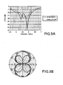
- Figure 3B shows the radiation patterns of the antenna system of Figure 3 in the E and H planes at a central operating frequency of 5.7 GHz. Since the system is produced on the same type of substrate as the system of Figure 1 , it can be seen that the cross polarization is less than -19.1 dB, especially in the axis of the antenna.
- Figure 3A shows the reflection coefficient S11 of the system of Figure 3 as a function of the frequency for a measurement and for a simulation.
- the antenna system is matched at -10 dB over 15.7% in simulation and 22% in measurement.
- This type of device may be produced, for example, by using triplate technology on two substrates of permittivity ⁇ r1 and ⁇ r2 .
- the two annular slots are etched on the top face of the first substrate.
- the supply line, made in microstrip technology, is produced between the two substrates and the earth plane is formed on the bottom face of the second substrate.
- the two annular slots may be provided with perturbations transforming in a known manner a linear polarization into a circular one. More specifically, each annular slot is provided with two diagonally opposed perturbations, the perturbations being positioned at around 45 or 135 degrees from the plane passing through the centre of said means of transmission and the first point of symmetry.
- the perturbations may be done by cuts or by projections of various shapes, as known from the art.
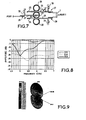
- the novel topology of the electromagnetic signal transmission system consists of three antennas 20, 21, 22 of the annular slot type. These slots are tangent in pairs at the points P1 and P2. More specifically, the annular slots 20 and 21 are tangent at the point P1 while the slots 21 and 22 are tangent at the point P2.
- the points P1 and P2 are therefore points of symmetry through which a plane, more particularly a plane of tangency, may pass.
- the slots 20, 21, 22 are supplied by microstrip lines 23, 24 which are respectively in the planes of tangency passing through the points P1 and P2.
- microstrip supply lines 23, 24 are joined by a T-shaped junction to the port 1 for connection with a supply circuit (not shown).
- the length of line 23 or 24 between the point P1 or P2 and the end 23' or 24' away from the port 1 is preferably about k ⁇ m /4 where k is an integer and ⁇ m the wavelength guided in the supply line.
- an electronic component making it possible to simulate a short circuit or an open circuit at the end of one of the lines and an open circuit or a short circuit at the end of the other line is mounted at the end of each of the lines 23, 24. More specifically, one diode 25 is reverse-mounted between the end 23' and the earth, while one diode 26 is forward-mounted between the end 24' and the earth.
- This mounting makes it possible to switch the radiation patterns between three states depending on the bias state of the diodes 25 and 26, this bias being produced in a manner known to a person skilled in the art.
- the various switching states are shown in Table 2 below: Table 2 Diode state Applied voltage Diode 25 Diode 26 -V Off On 0 Off Off +V On Off
- Figure 6 shows the three radiation states of the antenna according to the states of two ideal diodes at an operating frequency of 5.4 GHz.
- radiation diversity of order 3 is obtained for the antenna device.
- the two diodes 25, 26 must be in the on state, that is to say have a short circuit at the end of the microstrip lines 23 and 24 in transmission mode, and the diode 33 must be in the off state, that is to say have an open circuit CO at the end of the line 27 in transmission mode.
- the system shown in Figure 7 has four operating states, as mentioned in Table 3 below : Table 3 Diode state Diode 25 Diode 26 Diode 33 Rx State 1 Off On On State 2 Off Off On State 3 On Off On Tx State 4 On On Off
- the control device making it possible to manage these four states is provided by a device independently controlling each of the three diodes.
- This control device consists, for example, of block devices 28', 28 mounted between the T-junction and the supply lines 23, 24.
- the block devices consist of DC-blocks of known type.
- a DC-block 29 is also provided between the line 27 and the port 2.
- line ends or "stubs" 30, 31, 32 are mounted between the respective lines 32, 24 and 27 and the terminal for biasing the various diodes 25, 26 and 33.
- the length of each radial line end is such that an open circuit is restored at the intersection point. In this way, the bias voltage is provided to each of the diodes, without disturbing the radiofrequency RF (transparency condition).
- the DC-block device makes it possible to filter the DC current at the antenna access.
- the slot may have a shape other than an annular shape; it may have a polygonal shape, that is a square or rectangular shape or the like.
- the supply lines may be produced in microstrip technology or in coplanar technology.
- the diodes may be replaced by other components such as transistors, electronic switches and microelectromechanical systems.
Landscapes
- Engineering & Computer Science (AREA)
- Computer Networks & Wireless Communication (AREA)
- Signal Processing (AREA)
- Waveguide Aerials (AREA)
- Variable-Direction Aerials And Aerial Arrays (AREA)
- Details Of Aerials (AREA)
- Near-Field Transmission Systems (AREA)
Applications Claiming Priority (4)
| Application Number | Priority Date | Filing Date | Title |
|---|---|---|---|
| FR0113955A FR2831733B1 (fr) | 2001-10-29 | 2001-10-29 | Dispositif pour la reception et/ou l'emission de signaux electromagnetiques a diversite de rayonnement |
| FR0113955 | 2001-10-29 | ||
| FR0205419 | 2002-04-30 | ||
| FR0205419A FR2831734A1 (fr) | 2001-10-29 | 2002-04-30 | Dispositif pour la reception et/ou l'emission de signaux electromagnetiques a diversite de rayonnement |
Publications (2)
| Publication Number | Publication Date |
|---|---|
| EP1309035A1 EP1309035A1 (en) | 2003-05-07 |
| EP1309035B1 true EP1309035B1 (en) | 2008-04-02 |
Family
ID=26213234
Family Applications (1)
| Application Number | Title | Priority Date | Filing Date |
|---|---|---|---|
| EP02292593A Expired - Lifetime EP1309035B1 (en) | 2001-10-29 | 2002-10-21 | Switched antenna |
Country Status (9)
Families Citing this family (10)
| Publication number | Priority date | Publication date | Assignee | Title |
|---|---|---|---|---|
| FR2833764B1 (fr) * | 2001-12-19 | 2004-01-30 | Thomson Licensing Sa | Dispositif pour la reception et/ou l'emission de signaux electromagnetiques polarises circulairement |
| FR2859315A1 (fr) * | 2003-08-29 | 2005-03-04 | Thomson Licensing Sa | Antenne planaire multibandes |
| FR2861222A1 (fr) * | 2003-10-17 | 2005-04-22 | Thomson Licensing Sa | Antenne planaire bi-bande |
| FR2892862A1 (fr) * | 2005-10-27 | 2007-05-04 | Thomson Licensing Sas | Antenne d'emission/reception a diversite de rayonnement |
| TWI334241B (en) * | 2007-05-10 | 2010-12-01 | Asustek Comp Inc | Antenna |
| FR2917242A1 (fr) * | 2007-06-06 | 2008-12-12 | Thomson Licensing Sas | Perfectionnement aux antennes large bande. |
| CN102832446A (zh) * | 2011-06-17 | 2012-12-19 | 云南银河之星科技有限公司 | 一种立体四环圆极化天线 |
| CN103151604B (zh) * | 2013-03-01 | 2016-06-08 | 江苏省东方世纪网络信息有限公司 | 天线单元和天线 |
| CN103700932B (zh) * | 2013-12-27 | 2016-03-02 | 北京航天时代光电科技有限公司 | 一种小型化甚高频单极子类型天线 |
| CN111585050B (zh) * | 2020-05-18 | 2021-03-02 | 宁波大学 | 一种宽频带平板阵列天线 |
Citations (2)
| Publication number | Priority date | Publication date | Assignee | Title |
|---|---|---|---|---|
| EP0426972A1 (fr) * | 1989-09-11 | 1991-05-15 | Alcatel Espace | Antenne plane |
| WO2002069446A1 (fr) * | 2001-02-23 | 2002-09-06 | Thomson Licensing S.A. | Dispositif de reception et/ou d'emission de signaux electromagnetiques utilisable dans le domaine des transmissions sans fil |
Family Cites Families (7)
| Publication number | Priority date | Publication date | Assignee | Title |
|---|---|---|---|---|
| JPH0324804A (ja) * | 1989-06-21 | 1991-02-01 | Nippon Dengiyou Kosaku Kk | スロット形双ループアンテナ |
| JPH0324805A (ja) * | 1989-06-21 | 1991-02-01 | Nippon Dengiyou Kosaku Kk | スロット形双スパイラルアンテナ |
| CA2147399A1 (en) * | 1994-06-01 | 1995-12-02 | Noach Amitay | Feed structure for use in a wireless communication system |
| US6191740B1 (en) * | 1999-06-05 | 2001-02-20 | Hughes Electronics Corporation | Slot fed multi-band antenna |
| EP1158606B1 (en) * | 2000-05-26 | 2004-10-06 | Sony International (Europe) GmbH | Dual-spiral-slot antenna for circular polarization |
| EP1271692B1 (en) * | 2001-06-26 | 2004-03-31 | Sony International (Europe) GmbH | Printed planar dipole antenna with dual spirals |
| FR2828584A1 (fr) * | 2001-08-10 | 2003-02-14 | Thomson Licensing Sa | Dispositif pour la reception et/ou l'emission de signaux a diversite de rayonnement |
-
2002
- 2002-04-30 FR FR0205419A patent/FR2831734A1/fr active Pending
- 2002-10-16 JP JP2002301933A patent/JP4105522B2/ja not_active Expired - Lifetime
- 2002-10-16 KR KR1020020063124A patent/KR100941124B1/ko not_active Expired - Fee Related
- 2002-10-17 MX MXPA02010251A patent/MXPA02010251A/es active IP Right Grant
- 2002-10-21 ES ES02292593T patent/ES2304423T3/es not_active Expired - Lifetime
- 2002-10-21 EP EP02292593A patent/EP1309035B1/en not_active Expired - Lifetime
- 2002-10-21 DE DE60225886T patent/DE60225886T2/de not_active Expired - Lifetime
- 2002-10-24 CN CNB021480680A patent/CN100384100C/zh not_active Expired - Fee Related
- 2002-10-25 US US10/280,495 patent/US6917342B2/en not_active Expired - Lifetime
Patent Citations (2)
| Publication number | Priority date | Publication date | Assignee | Title |
|---|---|---|---|---|
| EP0426972A1 (fr) * | 1989-09-11 | 1991-05-15 | Alcatel Espace | Antenne plane |
| WO2002069446A1 (fr) * | 2001-02-23 | 2002-09-06 | Thomson Licensing S.A. | Dispositif de reception et/ou d'emission de signaux electromagnetiques utilisable dans le domaine des transmissions sans fil |
Non-Patent Citations (4)
| Title |
|---|
| "tangente (géomeétrie)", retrieved from WWW.WIKIPEDIA.ORG * |
| DUSSEUX M.T.: "Etude d'antennes fentes annulaires imprimées. Applications : Antennes mélangeurses, réseaux. (PhD Thesis)", 4 May 1987, UNIVERSITE DE RENNES 1, FRANCE * |
| MINARD P.; LOUZIR A.: "Annular Slot Antenna With 3-Order Radiation Pattern Diversity", 11TH SYMPOSIUM ON ANTENNA TECHNOLOGY AND APPLIED ELECTROMAGNETICS (ANTEM 2005), 15 June 2005 (2005-06-15), ST. MALO, FRANCE * |
| MINARD P.; LOUZIR A.: "Tangentially fed broadband annular slot antenna for WLAN applications", PROCEEDINGS OF 2002 INTERIM INTERNATIONAL SYMPOSIUM ON ANTENNAS AND PROPAGATION, 26 November 2002 (2002-11-26) - 28 November 2002 (2002-11-28), YOKUSUKA, JAPAN, pages 279 - 282 * |
Also Published As
| Publication number | Publication date |
|---|---|
| CN100384100C (zh) | 2008-04-23 |
| CN1417959A (zh) | 2003-05-14 |
| FR2831734A1 (fr) | 2003-05-02 |
| KR20030035908A (ko) | 2003-05-09 |
| JP4105522B2 (ja) | 2008-06-25 |
| EP1309035A1 (en) | 2003-05-07 |
| DE60225886T2 (de) | 2009-04-02 |
| MXPA02010251A (es) | 2005-11-04 |
| US6917342B2 (en) | 2005-07-12 |
| US20030080912A1 (en) | 2003-05-01 |
| JP2003188638A (ja) | 2003-07-04 |
| DE60225886D1 (de) | 2008-05-15 |
| KR100941124B1 (ko) | 2010-02-10 |
| ES2304423T3 (es) | 2008-10-16 |
Similar Documents
| Publication | Publication Date | Title |
|---|---|---|
| US7652632B2 (en) | Multiband omnidirectional planar antenna apparatus with selectable elements | |
| US6246377B1 (en) | Antenna comprising two separate wideband notch regions on one coplanar substrate | |
| US7864119B2 (en) | Antenna array | |
| US20060109067A1 (en) | Circuit board having a pereipheral antenna apparatus with selectable antenna elements and selectable phase shifting | |
| EP1267446B1 (en) | Device for the reception and/or the transmission of electromagnetic signals with radiation diversity | |
| US10622716B1 (en) | Balanced antenna | |
| CA2164669A1 (en) | Multi-branch miniature patch antenna having polarization and share diversity | |
| WO2001054229A9 (en) | Low profile high polarization purity dual-polarized antennas | |
| MXPA03007350A (es) | Dispositivo para recibir y/o transmitir senales electromagneticas para ser usadas en el campo de las transmisiones inalambricas. | |
| EP1309035B1 (en) | Switched antenna | |
| US6445346B2 (en) | Planar polarizer feed network for a dual circular polarized antenna array | |
| US7088302B2 (en) | Device for receiving and/or emitting electromagnetic waves with radiation diversity | |
| JP4208518B2 (ja) | 放射ダイバーシチを用いて信号を受信及び/又は発信する装置 | |
| KR101148970B1 (ko) | 광대역 전방향성 방사 디바이스 | |
| WO2004019445A2 (en) | Multi-layer antenna structure | |
| US20070080881A1 (en) | Transcoding mpeg bitstreams for adding sub-picture content | |
| JP2003152434A (ja) | 同一の2つのポート及び端子を有するコンパクトなプレーナ型アンテナ | |
| RU2719571C1 (ru) | Многофункциональный коммутатор для миллиметрового диапазона | |
| Sung | Circular Slot Antenna with Pattern Diversity | |
| KR100872489B1 (ko) | 방사 다이버시티를 갖는 전자기 신호의 수신 및/또는 송신용 디바이스 | |
| WO2006036116A1 (en) | Ring antenna | |
| HK1180836A (en) | Multiband omnidirectional planar antenna apparatus with selectable elements | |
| HK1180836B (en) | Multiband omnidirectional planar antenna apparatus with selectable elements |
Legal Events
| Date | Code | Title | Description |
|---|---|---|---|
| PUAI | Public reference made under article 153(3) epc to a published international application that has entered the european phase |
Free format text: ORIGINAL CODE: 0009012 |
|
| AK | Designated contracting states |
Designated state(s): AT BE BG CH CY CZ DE DK EE ES FI FR GB GR IE IT LI LU MC NL PT SE SK TR |
|
| AX | Request for extension of the european patent |
Extension state: AL LT LV MK RO SI |
|
| 17P | Request for examination filed |
Effective date: 20031020 |
|
| AKX | Designation fees paid |
Designated state(s): DE ES FR GB IT |
|
| 17Q | First examination report despatched |
Effective date: 20040319 |
|
| RAP1 | Party data changed (applicant data changed or rights of an application transferred) |
Owner name: THOMSON LICENSING |
|
| GRAP | Despatch of communication of intention to grant a patent |
Free format text: ORIGINAL CODE: EPIDOSNIGR1 |
|
| GRAS | Grant fee paid |
Free format text: ORIGINAL CODE: EPIDOSNIGR3 |
|
| GRAA | (expected) grant |
Free format text: ORIGINAL CODE: 0009210 |
|
| AK | Designated contracting states |
Kind code of ref document: B1 Designated state(s): DE ES FR GB IT |
|
| REG | Reference to a national code |
Ref country code: GB Ref legal event code: FG4D |
|
| REF | Corresponds to: |
Ref document number: 60225886 Country of ref document: DE Date of ref document: 20080515 Kind code of ref document: P |
|
| REG | Reference to a national code |
Ref country code: ES Ref legal event code: FG2A Ref document number: 2304423 Country of ref document: ES Kind code of ref document: T3 |
|
| ET | Fr: translation filed | ||
| PLBE | No opposition filed within time limit |
Free format text: ORIGINAL CODE: 0009261 |
|
| STAA | Information on the status of an ep patent application or granted ep patent |
Free format text: STATUS: NO OPPOSITION FILED WITHIN TIME LIMIT |
|
| 26N | No opposition filed |
Effective date: 20090106 |
|
| REG | Reference to a national code |
Ref country code: FR Ref legal event code: PLFP Year of fee payment: 14 |
|
| REG | Reference to a national code |
Ref country code: FR Ref legal event code: PLFP Year of fee payment: 15 |
|
| REG | Reference to a national code |
Ref country code: DE Ref legal event code: R082 Ref document number: 60225886 Country of ref document: DE Representative=s name: DEHNS, DE Ref country code: DE Ref legal event code: R082 Ref document number: 60225886 Country of ref document: DE Representative=s name: HOFSTETTER, SCHURACK & PARTNER PATENT- UND REC, DE |
|
| REG | Reference to a national code |
Ref country code: FR Ref legal event code: PLFP Year of fee payment: 16 |
|
| REG | Reference to a national code |
Ref country code: FR Ref legal event code: PLFP Year of fee payment: 17 |
|
| REG | Reference to a national code |
Ref country code: FR Ref legal event code: TP Owner name: THOMSON LICENSING DTV, FR Effective date: 20180830 |
|
| REG | Reference to a national code |
Ref country code: GB Ref legal event code: 732E Free format text: REGISTERED BETWEEN 20180927 AND 20181005 |
|
| REG | Reference to a national code |
Ref country code: DE Ref legal event code: R082 Ref document number: 60225886 Country of ref document: DE Representative=s name: DEHNS, DE Ref country code: DE Ref legal event code: R081 Ref document number: 60225886 Country of ref document: DE Owner name: INTERDIGITAL MADISON PATENT HOLDINGS, FR Free format text: FORMER OWNER: THOMSON LICENSING, BOULOGNE-BILLANCOURT, FR |
|
| REG | Reference to a national code |
Ref country code: ES Ref legal event code: PC2A Owner name: INTERDIGITAL MADISON PATENT HOLDINGS Effective date: 20190308 |
|
| PGFP | Annual fee paid to national office [announced via postgrant information from national office to epo] |
Ref country code: FR Payment date: 20191024 Year of fee payment: 18 Ref country code: ES Payment date: 20191125 Year of fee payment: 18 Ref country code: IT Payment date: 20191024 Year of fee payment: 18 |
|
| PGFP | Annual fee paid to national office [announced via postgrant information from national office to epo] |
Ref country code: GB Payment date: 20191029 Year of fee payment: 18 Ref country code: DE Payment date: 20191227 Year of fee payment: 18 |
|
| REG | Reference to a national code |
Ref country code: DE Ref legal event code: R119 Ref document number: 60225886 Country of ref document: DE |
|
| GBPC | Gb: european patent ceased through non-payment of renewal fee |
Effective date: 20201021 |
|
| PG25 | Lapsed in a contracting state [announced via postgrant information from national office to epo] |
Ref country code: DE Free format text: LAPSE BECAUSE OF NON-PAYMENT OF DUE FEES Effective date: 20210501 Ref country code: FR Free format text: LAPSE BECAUSE OF NON-PAYMENT OF DUE FEES Effective date: 20201031 |
|
| PG25 | Lapsed in a contracting state [announced via postgrant information from national office to epo] |
Ref country code: GB Free format text: LAPSE BECAUSE OF NON-PAYMENT OF DUE FEES Effective date: 20201021 |
|
| PG25 | Lapsed in a contracting state [announced via postgrant information from national office to epo] |
Ref country code: IT Free format text: LAPSE BECAUSE OF NON-PAYMENT OF DUE FEES Effective date: 20201021 |
|
| REG | Reference to a national code |
Ref country code: ES Ref legal event code: FD2A Effective date: 20220121 |
|
| PG25 | Lapsed in a contracting state [announced via postgrant information from national office to epo] |
Ref country code: ES Free format text: LAPSE BECAUSE OF NON-PAYMENT OF DUE FEES Effective date: 20201022 |