EP1308966A1 - Method for manufacturing zirconium-based alloys containing niobium for use in nuclear fuel rod cladding - Google Patents
Method for manufacturing zirconium-based alloys containing niobium for use in nuclear fuel rod cladding Download PDFInfo
- Publication number
- EP1308966A1 EP1308966A1 EP02015748A EP02015748A EP1308966A1 EP 1308966 A1 EP1308966 A1 EP 1308966A1 EP 02015748 A EP02015748 A EP 02015748A EP 02015748 A EP02015748 A EP 02015748A EP 1308966 A1 EP1308966 A1 EP 1308966A1
- Authority
- EP
- European Patent Office
- Prior art keywords
- ingot
- temperature
- cold
- working
- niobium
- Prior art date
- Legal status (The legal status is an assumption and is not a legal conclusion. Google has not performed a legal analysis and makes no representation as to the accuracy of the status listed.)
- Granted
Links
- 239000010955 niobium Substances 0.000 title claims abstract description 113
- 229910045601 alloy Inorganic materials 0.000 title claims abstract description 88
- 239000000956 alloy Substances 0.000 title claims abstract description 88
- 229910052758 niobium Inorganic materials 0.000 title claims abstract description 76
- GUCVJGMIXFAOAE-UHFFFAOYSA-N niobium atom Chemical compound [Nb] GUCVJGMIXFAOAE-UHFFFAOYSA-N 0.000 title claims abstract description 72
- 238000000034 method Methods 0.000 title claims abstract description 65
- QCWXUUIWCKQGHC-UHFFFAOYSA-N Zirconium Chemical compound [Zr] QCWXUUIWCKQGHC-UHFFFAOYSA-N 0.000 title claims abstract description 47
- 229910052726 zirconium Inorganic materials 0.000 title claims abstract description 47
- 239000003758 nuclear fuel Substances 0.000 title claims abstract description 37
- 238000005253 cladding Methods 0.000 title claims abstract description 36
- 238000004519 manufacturing process Methods 0.000 title claims abstract description 32
- 238000000137 annealing Methods 0.000 claims abstract description 116
- 238000005482 strain hardening Methods 0.000 claims abstract description 44
- 239000011159 matrix material Substances 0.000 claims abstract description 42
- 238000005260 corrosion Methods 0.000 claims abstract description 36
- 230000007797 corrosion Effects 0.000 claims abstract description 36
- 230000007423 decrease Effects 0.000 claims abstract description 17
- XLYOFNOQVPJJNP-UHFFFAOYSA-N water Substances O XLYOFNOQVPJJNP-UHFFFAOYSA-N 0.000 claims abstract description 14
- 238000010791 quenching Methods 0.000 claims abstract description 13
- 238000005242 forging Methods 0.000 claims abstract description 12
- 238000002844 melting Methods 0.000 claims abstract description 11
- 230000008018 melting Effects 0.000 claims abstract description 11
- XEEYBQQBJWHFJM-UHFFFAOYSA-N Iron Chemical compound [Fe] XEEYBQQBJWHFJM-UHFFFAOYSA-N 0.000 claims description 44
- 229910001093 Zr alloy Inorganic materials 0.000 claims description 34
- 238000010438 heat treatment Methods 0.000 claims description 27
- 239000002244 precipitate Substances 0.000 claims description 25
- 229910052760 oxygen Inorganic materials 0.000 claims description 17
- QVGXLLKOCUKJST-UHFFFAOYSA-N atomic oxygen Chemical compound [O] QVGXLLKOCUKJST-UHFFFAOYSA-N 0.000 claims description 14
- 239000010949 copper Substances 0.000 claims description 14
- 239000001301 oxygen Substances 0.000 claims description 14
- 229910052710 silicon Inorganic materials 0.000 claims description 14
- 229910052718 tin Inorganic materials 0.000 claims description 13
- 239000010703 silicon Substances 0.000 claims description 12
- 239000011651 chromium Substances 0.000 claims description 11
- ATJFFYVFTNAWJD-UHFFFAOYSA-N Tin Chemical compound [Sn] ATJFFYVFTNAWJD-UHFFFAOYSA-N 0.000 claims description 10
- 229910052802 copper Inorganic materials 0.000 claims description 10
- 229910052804 chromium Inorganic materials 0.000 claims description 8
- 230000003247 decreasing effect Effects 0.000 claims description 8
- 229910052742 iron Inorganic materials 0.000 claims description 8
- VYZAMTAEIAYCRO-UHFFFAOYSA-N Chromium Chemical compound [Cr] VYZAMTAEIAYCRO-UHFFFAOYSA-N 0.000 claims description 4
- RYGMFSIKBFXOCR-UHFFFAOYSA-N Copper Chemical compound [Cu] RYGMFSIKBFXOCR-UHFFFAOYSA-N 0.000 claims description 4
- XLYOFNOQVPJJNP-ZSJDYOACSA-N Heavy water Chemical compound [2H]O[2H] XLYOFNOQVPJJNP-ZSJDYOACSA-N 0.000 abstract description 4
- 239000000243 solution Substances 0.000 description 10
- 238000001816 cooling Methods 0.000 description 9
- XUIMIQQOPSSXEZ-UHFFFAOYSA-N Silicon Chemical compound [Si] XUIMIQQOPSSXEZ-UHFFFAOYSA-N 0.000 description 6
- PXHVJJICTQNCMI-UHFFFAOYSA-N Nickel Chemical compound [Ni] PXHVJJICTQNCMI-UHFFFAOYSA-N 0.000 description 5
- WMFOQBRAJBCJND-UHFFFAOYSA-M Lithium hydroxide Chemical compound [Li+].[OH-] WMFOQBRAJBCJND-UHFFFAOYSA-M 0.000 description 4
- 239000000306 component Substances 0.000 description 3
- 239000008358 core component Substances 0.000 description 3
- 229910000734 martensite Inorganic materials 0.000 description 3
- 239000000203 mixture Substances 0.000 description 3
- 238000012360 testing method Methods 0.000 description 3
- 210000001787 dendrite Anatomy 0.000 description 2
- 238000001125 extrusion Methods 0.000 description 2
- 229910052759 nickel Inorganic materials 0.000 description 2
- VSZWPYCFIRKVQL-UHFFFAOYSA-N selanylidenegallium;selenium Chemical compound [Se].[Se]=[Ga].[Se]=[Ga] VSZWPYCFIRKVQL-UHFFFAOYSA-N 0.000 description 2
- 239000011135 tin Substances 0.000 description 2
- 238000010313 vacuum arc remelting Methods 0.000 description 2
- 238000003466 welding Methods 0.000 description 2
- 229910001257 Nb alloy Inorganic materials 0.000 description 1
- 230000004913 activation Effects 0.000 description 1
- 238000005275 alloying Methods 0.000 description 1
- 239000007864 aqueous solution Substances 0.000 description 1
- 230000005540 biological transmission Effects 0.000 description 1
- 238000005097 cold rolling Methods 0.000 description 1
- 230000000052 comparative effect Effects 0.000 description 1
- 239000000470 constituent Substances 0.000 description 1
- 230000001747 exhibiting effect Effects 0.000 description 1
- 238000005098 hot rolling Methods 0.000 description 1
- 239000012535 impurity Substances 0.000 description 1
- 230000003340 mental effect Effects 0.000 description 1
- 238000012986 modification Methods 0.000 description 1
- 230000004048 modification Effects 0.000 description 1
- 229910052750 molybdenum Inorganic materials 0.000 description 1
- 239000002245 particle Substances 0.000 description 1
- 238000002360 preparation method Methods 0.000 description 1
- 230000000171 quenching effect Effects 0.000 description 1
- 238000001953 recrystallisation Methods 0.000 description 1
- 238000011160 research Methods 0.000 description 1
- 238000012827 research and development Methods 0.000 description 1
- 230000009466 transformation Effects 0.000 description 1
- 230000004584 weight gain Effects 0.000 description 1
- 235000019786 weight gain Nutrition 0.000 description 1
Images

Classifications
-
- C—CHEMISTRY; METALLURGY
- C22—METALLURGY; FERROUS OR NON-FERROUS ALLOYS; TREATMENT OF ALLOYS OR NON-FERROUS METALS
- C22C—ALLOYS
- C22C16/00—Alloys based on zirconium
-
- G—PHYSICS
- G21—NUCLEAR PHYSICS; NUCLEAR ENGINEERING
- G21C—NUCLEAR REACTORS
- G21C3/00—Reactor fuel elements and their assemblies; Selection of substances for use as reactor fuel elements
- G21C3/02—Fuel elements
- G21C3/04—Constructional details
- G21C3/06—Casings; Jackets
- G21C3/07—Casings; Jackets characterised by their material, e.g. alloys
-
- C—CHEMISTRY; METALLURGY
- C22—METALLURGY; FERROUS OR NON-FERROUS ALLOYS; TREATMENT OF ALLOYS OR NON-FERROUS METALS
- C22F—CHANGING THE PHYSICAL STRUCTURE OF NON-FERROUS METALS AND NON-FERROUS ALLOYS
- C22F1/00—Changing the physical structure of non-ferrous metals or alloys by heat treatment or by hot or cold working
- C22F1/16—Changing the physical structure of non-ferrous metals or alloys by heat treatment or by hot or cold working of other metals or alloys based thereon
- C22F1/18—High-melting or refractory metals or alloys based thereon
- C22F1/186—High-melting or refractory metals or alloys based thereon of zirconium or alloys based thereon
-
- Y—GENERAL TAGGING OF NEW TECHNOLOGICAL DEVELOPMENTS; GENERAL TAGGING OF CROSS-SECTIONAL TECHNOLOGIES SPANNING OVER SEVERAL SECTIONS OF THE IPC; TECHNICAL SUBJECTS COVERED BY FORMER USPC CROSS-REFERENCE ART COLLECTIONS [XRACs] AND DIGESTS
- Y02—TECHNOLOGIES OR APPLICATIONS FOR MITIGATION OR ADAPTATION AGAINST CLIMATE CHANGE
- Y02E—REDUCTION OF GREENHOUSE GAS [GHG] EMISSIONS, RELATED TO ENERGY GENERATION, TRANSMISSION OR DISTRIBUTION
- Y02E30/00—Energy generation of nuclear origin
- Y02E30/30—Nuclear fission reactors
Definitions
- the present invention relates to a method for manufacturing zirconium-based alloys containing niobium for use in nuclear fuel rod cladding, wherein the manufactured alloy exhibits improved corrosion resistance.
- zirconium alloys have been widely applied to nuclear reactors, such as light water reactors and heavy water reactors. Such applications include nuclear fuel rod cladding, space grids, and reactor core components.
- zirconium alloys thus-far developed Zircaloy-2 and Zircaloy-4 have been widely utilized.
- Zircaloy-2 is comprised of 1.20-1.70wt% of tin (Sn), 0.07-0.20wt% of iron (Fe), 0.05-1.15wt% of chromium (Cr), 0.03-0.08wt% of nickel (Ni), 900-1500ppm of oxygen (O), and the balance of zirconium (Zr); and zircaloy-4 is comprised of 1.20-1.70wt% of tin, 0.18-0.24wt% of iron, 0.07-1.13wt% of chromium, less than 0.07wt% of nickel, 900-1500ppm of oxygen, and the balance of zirconium.
- Zircaloy-2 and Zircaloy-4 could not be utilized as nuclear fuel rod cladding.
- an extensive and successful research and development have been focused on increasing the corrosion resistance of zirconium-based alloys.
- a notable feature of the zirconium-based alloy developed in this manner is that the nuclear fuel rod cladding contains niobium to improve corrosion resistance.
- the corrosion resistance of the zirconium-based alloy containing niobium depends on the alloying element, the size of precipitate in microstructure and the annealing condition. Particularly, the corrosion resistance of the zirconium-based alloy containing more than 1.0 wt% of niobium changes sensitively in the variation of niobium contents and annealing temperature. Therefore, to manufacture zirconium-based alloy containing niobium with superior corrosion resistance for use in nuclear fuel rod cladding, above all things, it is very important to establish an optimal manufacturing method.
- the prior art related to the method for manufacturing Nb-containing zirconium alloys for use in nuclear fuel cladding tubes, space grids, and reactor core components is as following.
- US Patent No. 5,838,753 EP Patent No. 895,247, 910,098, and 1,111,623, and JP Patent No. 11,109,072 disclose a method for manufacturing zirconium alloy comprising Nb (0.5-3.25 wt%) and Sn (0.3-1.8 wt%) for use in cladding tubes of high burn-up nuclear fuels.
- the method comprises heating the zirconium alloy billet at ⁇ range temperature above 950°C and rapidly quenching the heated billet below a transformation temperature from ( ⁇ + ⁇ ) to ⁇ to form a martensitic structure; extruding the quenched billet below 600°C to form a hollow billet; annealing the extruded billet below 590°C; cold-working the annealed billet; and intermediate annealing to form nuclear fuel cladding tubes.
- the nuclear fuel rod cladding tube has a microstructure in which second phase precipitates of ⁇ -Nb are distributed uniformly, intragranularly and intergranularly in the alloy matrix, thereby having a microstructure with excellent stability when irradiated by neutron.
- WO Patent No. 2001-061062 discloses a method for manufacturing a nuclear fuel cladding tube comprising a low content of Sn and 0.60-2wt% of Nb.
- Sn/Fe ratio is 0.25/0.5, 0.4/(0.35-0.5) or 0.5/(0.25-0.5). More than 0.75wt% of Fe+Sn is added to the nuclear fuel cladding tube.
- the method is composed of vacuum melting, forging, and hot- and cold-rolling, followed by annealing.
- the thus-obtained alloy has ⁇ -Nb of small size and Zr-Nb-Fe precipitates uniformly distributed in the zirconium matrix.
- JP Patent No. 2001-208879 discloses a nuclear fuel assembly composition comprising a welding part, wherein a zirconium alloy or a zircaloy alloy comprising 0.2-1.5wt% of Nb is treated at a temperature of 400-620°C to increase the corrosion resistance of the welding part.
- WO Patent Nos. 2001-024193 and 2001-024194 disclose a zirconium alloy for reactor core components.
- the zirconium alloy comprises 0.02-1wt% of Fe, 0.8-2.3wt% of Nb, 2000ppm or less of Sn, 2000ppm or less of O, 5-35ppm of S, and 0.25wt% or less of Cr+V.
- JP Patent No. 01-1158591 discloses a method for manufacturing zirconium alloy for a structure of reactor core or nuclear fuel cladding tube.
- the method consists of ⁇ -quenching, hot-working, cold-working, intermediate heat-treatment, final cold-working, and final annealing.
- At least one heat-treatment should comprise heating the zirconium alloy to above 750°C, and cooling it to 500°C at a rate of about 40°C/s.
- Final annealing is then performed at 450-500°C.
- JP Patent No. 06-049608 discloses a method for manufacturing zirconium alloy plate comprising steps of performing a solution heat-treatment, hot-working, heat-treatment, cold-working, and final annealing.
- the intermediate heat-treatment between the repeated cold-workings is performed once or several times so that the accumulated annealing parameter is limited to a range of 3 ⁇ 10 -18 to 2 ⁇ 10 -16 .
- the temperature for hot-working is 700-800°C and the annealing temperature is 400-650°C.
- JP Patent No. 04-329855 discloses a method for manufacturing zirconium alloy comprising steps of melting Zr-2.5wt% Nb alloy component, performing a solution heat-treatment at 870°C for thirty minutes, water cooling, cold-working at a working percentage of 3.9%, and annealing at 500°C for 24 hours.
- the ( ⁇ + ⁇ ) type zirconium alloy is manufactured by a method comprising steps of performing a solution heat-treatment, cold-working at a working percentage of 1-5%, and annealing, the zirconium alloy exhibits high corrosion resistance and creep resistance.
- JP Patent No. 63-050453 discloses a method for manufacturing zirconium alloy comprising steps of solution heat-treating a zirconium alloy comprising Nb, Sn, and Mo, cooling from ( ⁇ + ⁇ ) phase range or ⁇ phase range, cold-working, heating to a temperature higher than eutectoid temperature, cooling again, and annealing at ⁇ phase range lower than eutectoid temperature.
- the thus-obtained zirconium alloy exhibits properties of high strength and high corrosion resistance.
- JP Patent No. 62-182258 discloses a method for manufacturing zirconium alloy comprising steps of solution heat-treating the zirconium alloy comprising 0.2-5wt% of Nb, 0.5-3wt% of Sn, 0.1-2wt% of Fe, and 500-2000ppm of O, at ( ⁇ + ⁇ ) phase range or ⁇ phase range; rapid cooling at a high rate; cold-working at an extrusion percentage above 15%; and annealing at a temperature higher than recrystallization temperature at the ⁇ phase range.
- the thus-obtained zirconium alloy exhibits excellent ductility and corrosion resistance.
- the zirconium alloy comprising 2.5wt% of Nb, 1.0wt% of Sn, 0.15wt% of Fe, and 1210ppm of O is prepared as a 9 mm thick cold-rolled plate by a method which comprises heating at 940°C for thirty minutes, water cooling, cold-working with a extrusion percentage of 40%, and annealing at 400°C for twenty minutes.
- the alloy exhibits similar mechanical properties as that of the zirconium alloy comprising 2.5wt% of Nb and 1230ppm of O.
- the present invention provides a method for manufacturing zirconium-based alloy containing niobium comprising steps of:
- the present invention provides a method for manufacturing a zirconium-based alloy for use in nuclear fuel cladding tubes, comprising 1.1-1.7wt% of niobium (Nb); 600-1600ppm of oxygen (O); 80-120ppm of silicon (Si), and the balance of zirconium (Zr).
- the present invention provides a method for manufacturing a zirconium-based alloy for use in nuclear fuel cladding tubes, comprising 1.1-1.7wt% of niobium; 0.01-0.15wt% of copper (Cu); 600-1600ppm of oxygen; 80-120ppm of silicon, and the balance of zirconium.
- the present invention provides a method for manufacturing a zirconium-based alloy for use in nuclear fuel cladding tubes, comprising 1.1-1.7wt% of niobium; 0.3-0.7wt% of tin (Sn); 600-1600ppm of oxygen; 80-120ppm of silicon, and the balance of zirconium.
- the present invention provides a method for manufacturing a zirconium-based alloy for use in nuclear fuel cladding tubes, comprising 1.1-1.7wt% of niobium; 0.3-0.7wt% of tin; 0.05-0.4wt% of iron (Fe); 600-1600ppm of oxygen; 80-120ppm of silicon, and the balance of zirconium.
- the present invention provides a method for manufacturing a zirconium-based alloy for use in nuclear fuel cladding tubes, comprising 1.1-1.7wt% of niobium; 0.3-0.7wt% of tin; 0.05-0.4wt% of iron; 0.05-0.2wt% of chromium; 600-1600ppm of oxygen; 80-120ppm of silicon, and the balance of zirconium.
- the present invention provides a method for manufacturing a zirconium-based alloy for use in nuclear fuel cladding tubes, comprising 1.1-1.7wt% of niobium; 0.3-0.7wt% of tin; 0.05-0.4wt% of iron; 0.05-0.2wt% of copper; 600-1600ppm of oxygen; 80-120ppm of silicon, and the balance of zirconium.
- the zirconium-based alloy of the present invention is manufactured by a method comprising the steps of (a) melting an ingot of the alloy component; (b) forging the ingot at a ⁇ phase temperature above 1000°C; (c) ⁇ -quenching the forged ingot in water after performing a solution heat-treatment at ⁇ phase range of 1000°C; (d) hot-working the ⁇ quenched ingot at a temperature of 600-640°C; (e) vacuum annealing the hot-worked ingot at 570-610°C; (f) cold-working the annealed ingot in three to four passes, with an intermediate annealing step performed between each pass, wherein the intermediate annealing step is performed at a temperature of 570-610°C in a vacuum; and (g) final annealing the cold-worked ingot at a temperature of 470-580°C.
- the concentration of niobium in the ⁇ -Zr matrix decreases from the supersaturation state to the equilibrium state which is maintained at operation temperature of nuclear reactor. As a result, corrosion resistance can be improved.
- step (a) alloy elements such as Nb, Sn, Fe, Cr, Cu, O, and Si are mixed with Zr and then melted. All of the constituents of the Zr-alloy of the present invention are melted by vacuum arc remelting (VAR) method.
- VAR vacuum arc remelting
- step (b) an ingot is forged at ⁇ phase range above 1000°C to break its dendrite structure.
- the forging temperature is preferably 1100-1200°C.
- step (c) solution heat-treatment of the ingot is preformed at ⁇ phase range above 1000°C so that the alloy composition may become homogeneous, and then is quenched to yield a martensite structure or widmanstatten structure.
- This step is carried out for homogenizing the composition and controlling the particle sizes of precipitates in the alloy matrix.
- the solution heat-treatment temperature is preferably ⁇ phase range of 1050-1100°C, and the cooling is performed from ⁇ phase range to below 400°C at a cooling rate greater than 300°C/s.
- step (d) the ⁇ -quenched ingot is worked into a hollow billet and hot-worked to prepare an extruded bar, which is suitable for cold working.
- the heat treatment temperature is preferably 600-640°C, more preferably 630°C.
- step (e) the hot-worked ingot is heat-treated at 570-610°C, and preferably at 580°C, for three hours.
- step (f) the extruded bar of step (e) is cold-worked to form a nuclear fuel cladding tube (the final size has an outside diameter of 9.5mm and a thickness of 0.57mm). Then, it is heat-treated in the intermediate vacuum annealing steps between each cold-working step so as to prepare recrystallized structure, to attain small ⁇ -Nb precipitates which are distributed uniformly, and for the concentration of Nb to reach equilibrium concentration.
- the intermediate heat-treatment temperature is 570-610°C and its duration is generally 30-100 hours.
- the extruded bar is cold-worked only for three times to manufacture nuclear fuel cladding tube of final size. At this time, the intermediate annealing temperature is 580°C, to control the condition under which the concentration of niobium in the ⁇ -Zr matrix becomes equilibrium concentration, and the heat-treatment duration is generally 3 to 10 hours.
- step (g) the nuclear fuel cladding tube prepared as final size is final annealed under vacuum and the zirconium alloy of the present invention is final annealed at 470-580°C for 3 hours.
- the zirconium alloy of the present invention is heat-treated for a long duration to make the Nb concentration in the ⁇ -Zr matrix reach equilibrium concentration, but since the size of precipitates may increase at this case, the heat-treatment duration and temperature are controlled so that the maximum size of precipitates is limited and the average size of precipitates does not increase.
- an accumulated annealing parameter ⁇ A is preferably limited to less than 1 ⁇ 10 -18 hours, so that the average size of precipitates does not excess 80nm.
- the zirconium-based alloy containing niobium of present invention comprises:
- the concentration of niobium in the ⁇ -Zr matrix decreases from the supersaturation state to the equilibrium state which is maintained at operation temperature of nuclear reactor. As a result, corrosion resistance can be improved.
- the alloy elements such as Nb, Sn, Fe, Cr, Cu, O and Si shown in table 1 were mixed with Zr and then melted to form an ingot.
- Forging was performed in the ⁇ phase range of 1100°c in order that the dendrite structures in the ingot were broken.
- solution heat-treatment was conducted at ⁇ phase range of 1050°C and then it was cooled from ⁇ phase range to below 400°C at a cooling rate greater than 300°C/s so that alloy elements were homogeneously distributed and martensite or widmanstatten structure could be obtained.
- the ⁇ -quenched ingot was hot-worked at 630°C to yield an extruded shell, suitable for cold working after being worked into hollow billet.
- the got-worked ingot was heat-treated at 580°C for 3 hours.
- the extruded bar was cold-worked in four passes to prepare nuclear fuel rod cladding tube of final size, 9.5 mm of outside diameter and 0.57 mm of thickness.
- the intermediate heat-treatment is performed in vacuum between each pass.
- intermediate annealing is performed at a temperature of 580°C and 620°C, respectively. In each step, wherein the intermediate annealing time is 10 hours for each step, 30 hours in total.
- the extruded bar is cold-worked only in three passes to prepare final size of nuclear fuel rod cladding tube.
- Intermediate annealing is performed at temperature of 580°C so that the Nb concentration in the ⁇ -Zr matrix maintains equilibrium concentration, wherein the intermediate annealing time is 5 hours for each step and 10 hours in total.
- the final annealing for the tube with final size is performed in vacuum at 470-580°C for 3 hour to prepare zirconium-based alloy for use in nuclear fuel rod cladding tubes.
- zirconium-based alloys of the present invention displayed a significantly slighter increase in weight and a higher corrosion resistance than the Zircaloy-4.
- zirconium-based alloys cold-worked for three times and intermediate-annealed at 580°C for 10 hours displayed similar corrosion resistance to that cold-worked for four times and intermediate-annealed at 580°C for 30 hours.
- Intermediate annealing time to obtain excellent microstructure could be decreased by increasing the degree of cold working.
- the experimental alloys 3, 8, 13, 18, 23 and 28 were subjected to cold-working for four times and intermediate annealing at 580°C and 620°C, respectively.
- the microstructure of the obtained experimental alloys was observed by a transmission electron microscope.
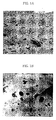
- Figs 1A and 1B are photomicrographs showing the microstructure of the experimental alloy 28. Results of type and size of precipitates in experimental alloys 3, 8, 13, 18, 23 and 28 are shown in the following table 3.
- ⁇ -Nb is precipitated in the experimental alloy intermediate-annealed at 580°C
- ⁇ -Zr is precipitated in the experimental alloy intermediate-annealed at 620°C.
- the average diameter of precipitates is 50-80 nm for alloys intermediate-annealed at 580°C and 100-140 nm for alloys intermediate-annealed at 620°C.
- the obtained zirconium-based alloys containing niobium exhibits improved corrosion resistance when ⁇ -Nb was formed and the size of precipitates is smaller than 80 nm by intermediate annealing at 580°C.
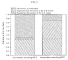
- Fig 2 is a graph illustrating the relation between the relative content of niobium comprising each phase of alloy in the present invention and corrosion resistance.
- ⁇ -Nb containing a relatively large quantity of niobium was precipitated in alloy performing intermediate annealing at 580°C and the niobium concentration in the ⁇ -Zr matrix decreased to the level of equilibrium concentration.
- ⁇ -Zr containing a relatively small quantity of niobium was precipitated in alloy intermediate-annealed at 620°C and the niobium concentration in the ⁇ -Zr matrix was supersaturated than the equilibrium concentration.
- niobium concentration in the ⁇ -Zr matrix is 0.3-0.6 wt%, the corrosion resistance of alloy is the highest.
- the zirconium-based alloy of the present invention exhibits improved corrosion resistance when the concentration of niobium in the ⁇ -Zr matrix decreases to the level of equilibrium concentration by intermediate annealing at 580°C.
Landscapes
- Engineering & Computer Science (AREA)
- Chemical & Material Sciences (AREA)
- Physics & Mathematics (AREA)
- Metallurgy (AREA)
- Organic Chemistry (AREA)
- Materials Engineering (AREA)
- Mechanical Engineering (AREA)
- Plasma & Fusion (AREA)
- General Engineering & Computer Science (AREA)
- High Energy & Nuclear Physics (AREA)
- Crystallography & Structural Chemistry (AREA)
- Thermal Sciences (AREA)
- Forging (AREA)
- Monitoring And Testing Of Nuclear Reactors (AREA)
- Powder Metallurgy (AREA)
- Fuel-Injection Apparatus (AREA)
- Heat Treatment Of Steel (AREA)
Abstract
Description
- The present invention relates to a method for manufacturing zirconium-based alloys containing niobium for use in nuclear fuel rod cladding, wherein the manufactured alloy exhibits improved corrosion resistance.
- In the past, zirconium alloys have been widely applied to nuclear reactors, such as light water reactors and heavy water reactors. Such applications include nuclear fuel rod cladding, space grids, and reactor core components. Among zirconium alloys thus-far developed, Zircaloy-2 and Zircaloy-4 have been widely utilized. Here, Zircaloy-2 is comprised of 1.20-1.70wt% of tin (Sn), 0.07-0.20wt% of iron (Fe), 0.05-1.15wt% of chromium (Cr), 0.03-0.08wt% of nickel (Ni), 900-1500ppm of oxygen (O), and the balance of zirconium (Zr); and zircaloy-4 is comprised of 1.20-1.70wt% of tin, 0.18-0.24wt% of iron, 0.07-1.13wt% of chromium, less than 0.07wt% of nickel, 900-1500ppm of oxygen, and the balance of zirconium.
- As the operating condition of nuclear power plants tends to be at high burnup, increased operating temperature, and high pH, Zircaloy-2 and Zircaloy-4 could not be utilized as nuclear fuel rod cladding. Recently, an extensive and successful research and development have been focused on increasing the corrosion resistance of zirconium-based alloys. A notable feature of the zirconium-based alloy developed in this manner is that the nuclear fuel rod cladding contains niobium to improve corrosion resistance.
- The corrosion resistance of the zirconium-based alloy containing niobium depends on the alloying element, the size of precipitate in microstructure and the annealing condition. Particularly, the corrosion resistance of the zirconium-based alloy containing more than 1.0 wt% of niobium changes sensitively in the variation of niobium contents and annealing temperature. Therefore, to manufacture zirconium-based alloy containing niobium with superior corrosion resistance for use in nuclear fuel rod cladding, above all things, it is very important to establish an optimal manufacturing method.
- The prior art related to the method for manufacturing Nb-containing zirconium alloys for use in nuclear fuel cladding tubes, space grids, and reactor core components is as following.
- US Patent No. 5,838,753, EP Patent No. 895,247, 910,098, and 1,111,623, and JP Patent No. 11,109,072 disclose a method for manufacturing zirconium alloy comprising Nb (0.5-3.25 wt%) and Sn (0.3-1.8 wt%) for use in cladding tubes of high burn-up nuclear fuels. The method comprises heating the zirconium alloy billet at β range temperature above 950°C and rapidly quenching the heated billet below a transformation temperature from (α+β) to α to form a martensitic structure; extruding the quenched billet below 600°C to form a hollow billet; annealing the extruded billet below 590°C; cold-working the annealed billet; and intermediate annealing to form nuclear fuel cladding tubes. As such, the nuclear fuel rod cladding tube has a microstructure in which second phase precipitates of β-Nb are distributed uniformly, intragranularly and intergranularly in the alloy matrix, thereby having a microstructure with excellent stability when irradiated by neutron.
- WO Patent No. 2001-061062 discloses a method for manufacturing a nuclear fuel cladding tube comprising a low content of Sn and 0.60-2wt% of Nb. Sn/Fe ratio is 0.25/0.5, 0.4/(0.35-0.5) or 0.5/(0.25-0.5). More than 0.75wt% of Fe+Sn is added to the nuclear fuel cladding tube. The method is composed of vacuum melting, forging, and hot- and cold-rolling, followed by annealing. The thus-obtained alloy has β-Nb of small size and Zr-Nb-Fe precipitates uniformly distributed in the zirconium matrix.
- JP Patent No. 2001-208879 discloses a nuclear fuel assembly composition comprising a welding part, wherein a zirconium alloy or a zircaloy alloy comprising 0.2-1.5wt% of Nb is treated at a temperature of 400-620°C to increase the corrosion resistance of the welding part.
- WO Patent Nos. 2001-024193 and 2001-024194 disclose a zirconium alloy for reactor core components. The zirconium alloy comprises 0.02-1wt% of Fe, 0.8-2.3wt% of Nb, 2000ppm or less of Sn, 2000ppm or less of O, 5-35ppm of S, and 0.25wt% or less of Cr+V.
- JP Patent No. 01-1158591 discloses a method for manufacturing zirconium alloy for a structure of reactor core or nuclear fuel cladding tube. The method consists of β-quenching, hot-working, cold-working, intermediate heat-treatment, final cold-working, and final annealing. At least one heat-treatment should comprise heating the zirconium alloy to above 750°C, and cooling it to 500°C at a rate of about 40°C/s. Final annealing is then performed at 450-500°C.
- JP Patent No. 06-049608 discloses a method for manufacturing zirconium alloy plate comprising steps of performing a solution heat-treatment, hot-working, heat-treatment, cold-working, and final annealing. The intermediate heat-treatment between the repeated cold-workings is performed once or several times so that the accumulated annealing parameter is limited to a range of 3×10-18 to 2×10-16. The temperature for hot-working is 700-800°C and the annealing temperature is 400-650°C.
- JP Patent No. 04-329855 discloses a method for manufacturing zirconium alloy comprising steps of melting Zr-2.5wt% Nb alloy component, performing a solution heat-treatment at 870°C for thirty minutes, water cooling, cold-working at a working percentage of 3.9%, and annealing at 500°C for 24 hours. When the (α+β) type zirconium alloy is manufactured by a method comprising steps of performing a solution heat-treatment, cold-working at a working percentage of 1-5%, and annealing, the zirconium alloy exhibits high corrosion resistance and creep resistance.
- JP Patent No. 63-050453 discloses a method for manufacturing zirconium alloy comprising steps of solution heat-treating a zirconium alloy comprising Nb, Sn, and Mo, cooling from (α+β) phase range or β phase range, cold-working, heating to a temperature higher than eutectoid temperature, cooling again, and annealing at α phase range lower than eutectoid temperature. The thus-obtained zirconium alloy exhibits properties of high strength and high corrosion resistance.
- JP Patent No. 62-182258 discloses a method for manufacturing zirconium alloy comprising steps of solution heat-treating the zirconium alloy comprising 0.2-5wt% of Nb, 0.5-3wt% of Sn, 0.1-2wt% of Fe, and 500-2000ppm of O, at (α+β) phase range or β phase range; rapid cooling at a high rate; cold-working at an extrusion percentage above 15%; and annealing at a temperature higher than recrystallization temperature at the α phase range. The thus-obtained zirconium alloy exhibits excellent ductility and corrosion resistance. Also, the zirconium alloy comprising 2.5wt% of Nb, 1.0wt% of Sn, 0.15wt% of Fe, and 1210ppm of O is prepared as a 9 mm thick cold-rolled plate by a method which comprises heating at 940°C for thirty minutes, water cooling, cold-working with a extrusion percentage of 40%, and annealing at 400°C for twenty minutes. The alloy exhibits similar mechanical properties as that of the zirconium alloy comprising 2.5wt% of Nb and 1230ppm of O.
- As described above with respect to the prior art, research has been carried out on conventional zirconium-based alloy containing niobium for use in nuclear fuel cladding tubes, to impart high corrosion resistance by changing the type and amount of elements to be added.
- Leading to the present invention, we developed an optimized method for manufacturing zirconium-based alloy containing niobium exhibiting improved corrosion resistance which depends on the size and type of precipitate, an accumulated annealing parameter, and niobium concentration in the α-Zr matrix.
- It is the objective of this invention to provide a method for manufacturing zirconium-based alloy containing niobium for use in nuclear fuel rod cladding tubes.
- In order to attain the above objective, the present invention provides a method for manufacturing zirconium-based alloy containing niobium comprising steps of:
- melting an ingot of the alloy component;
- forging the ingot at a β phase temperature above 1000°C;
- β-quenching the forged ingot in water after performing a solution heat-treatment at β phase range of 1000°C;
- hot-working the β quenched ingot at a temperature of 600-640°C;
- vacuum annealing the hot-worked ingot at 570-610°C;
- cold-working the annealed ingot in three to four passes, with an intermediate annealing step performed between each pass, wherein the intermediate annealing step is performed at a temperature of 570-610°C in a vacuum; and
- final-annealing the cold-worked ingot at a temperature of 470-580°C, whereby the niobium concentration in the α-Zr matrix decreases from the supersaturation state to the equilibrium state.
-
- As a first aspect, the present invention provides a method for manufacturing a zirconium-based alloy for use in nuclear fuel cladding tubes, comprising 1.1-1.7wt% of niobium (Nb); 600-1600ppm of oxygen (O); 80-120ppm of silicon (Si), and the balance of zirconium (Zr).
- As a second aspect, the present invention provides a method for manufacturing a zirconium-based alloy for use in nuclear fuel cladding tubes, comprising 1.1-1.7wt% of niobium; 0.01-0.15wt% of copper (Cu); 600-1600ppm of oxygen; 80-120ppm of silicon, and the balance of zirconium.
- As a third aspect, the present invention provides a method for manufacturing a zirconium-based alloy for use in nuclear fuel cladding tubes, comprising 1.1-1.7wt% of niobium; 0.3-0.7wt% of tin (Sn); 600-1600ppm of oxygen; 80-120ppm of silicon, and the balance of zirconium.
- As a fourth aspect, the present invention provides a method for manufacturing a zirconium-based alloy for use in nuclear fuel cladding tubes, comprising 1.1-1.7wt% of niobium; 0.3-0.7wt% of tin; 0.05-0.4wt% of iron (Fe); 600-1600ppm of oxygen; 80-120ppm of silicon, and the balance of zirconium.
- As a fifth aspect, the present invention provides a method for manufacturing a zirconium-based alloy for use in nuclear fuel cladding tubes, comprising 1.1-1.7wt% of niobium; 0.3-0.7wt% of tin; 0.05-0.4wt% of iron; 0.05-0.2wt% of chromium; 600-1600ppm of oxygen; 80-120ppm of silicon, and the balance of zirconium.
- As a sixth aspect, the present invention provides a method for manufacturing a zirconium-based alloy for use in nuclear fuel cladding tubes, comprising 1.1-1.7wt% of niobium; 0.3-0.7wt% of tin; 0.05-0.4wt% of iron; 0.05-0.2wt% of copper; 600-1600ppm of oxygen; 80-120ppm of silicon, and the balance of zirconium.
- The above and other objects, features and other advantages of the present invention will be more clearly understood from the following detailed description taken in conjunction with the accompanying drawings in which:
- Figs. 1A and 1B are photomicrographs showing the microstructure of an experimental alloy 28 subjected to intermediate vacuum annealing at 580°C and 620°C, respectively;
- Fig. 2 is a graph illustrating the relation between the relative content of niobium comprising each phase of alloy in the present invention and corrosion resistance; and
- Fig. 3 is a graph illustrating the relation between the content of niobium comprising the α-Zr matrix of alloy manufactured according to the present invention and corrosion resistance.
-
- The zirconium-based alloy of the present invention is manufactured by a method comprising the steps of (a) melting an ingot of the alloy component; (b) forging the ingot at a β phase temperature above 1000°C; (c) β-quenching the forged ingot in water after performing a solution heat-treatment at β phase range of 1000°C; (d) hot-working the β quenched ingot at a temperature of 600-640°C; (e) vacuum annealing the hot-worked ingot at 570-610°C; (f) cold-working the annealed ingot in three to four passes, with an intermediate annealing step performed between each pass, wherein the intermediate annealing step is performed at a temperature of 570-610°C in a vacuum; and (g) final annealing the cold-worked ingot at a temperature of 470-580°C.
- According to the method of the present invention, the concentration of niobium in the α-Zr matrix decreases from the supersaturation state to the equilibrium state which is maintained at operation temperature of nuclear reactor. As a result, corrosion resistance can be improved.
- In step (a), alloy elements such as Nb, Sn, Fe, Cr, Cu, O, and Si are mixed with Zr and then melted. All of the constituents of the Zr-alloy of the present invention are melted by vacuum arc remelting (VAR) method.
- In step (b), an ingot is forged at β phase range above 1000°C to break its dendrite structure. The forging temperature is preferably 1100-1200°C.
- In step (c), solution heat-treatment of the ingot is preformed at β phase range above 1000°C so that the alloy composition may become homogeneous, and then is quenched to yield a martensite structure or widmanstatten structure. This step is carried out for homogenizing the composition and controlling the particle sizes of precipitates in the alloy matrix. The solution heat-treatment temperature is preferably β phase range of 1050-1100°C, and the cooling is performed from β phase range to below 400°C at a cooling rate greater than 300°C/s.
- In step (d), the β-quenched ingot is worked into a hollow billet and hot-worked to prepare an extruded bar, which is suitable for cold working. At this time, the heat treatment temperature is preferably 600-640°C, more preferably 630°C.
- In step (e), the hot-worked ingot is heat-treated at 570-610°C, and preferably at 580°C, for three hours.
- In step (f), the extruded bar of step (e) is cold-worked to form a nuclear fuel cladding tube (the final size has an outside diameter of 9.5mm and a thickness of 0.57mm). Then, it is heat-treated in the intermediate vacuum annealing steps between each cold-working step so as to prepare recrystallized structure, to attain small β-Nb precipitates which are distributed uniformly, and for the concentration of Nb to reach equilibrium concentration. The intermediate heat-treatment temperature is 570-610°C and its duration is generally 30-100 hours. On the other hand, increasing manufacturing efficiency, the extruded bar is cold-worked only for three times to manufacture nuclear fuel cladding tube of final size. At this time, the intermediate annealing temperature is 580°C, to control the condition under which the concentration of niobium in the α-Zr matrix becomes equilibrium concentration, and the heat-treatment duration is generally 3 to 10 hours.
- In step (g), the nuclear fuel cladding tube prepared as final size is final annealed under vacuum and the zirconium alloy of the present invention is final annealed at 470-580°C for 3 hours.
- The zirconium alloy of the present invention is heat-treated for a long duration to make the Nb concentration in the α-Zr matrix reach equilibrium concentration, but since the size of precipitates may increase at this case, the heat-treatment duration and temperature are controlled so that the maximum size of precipitates is limited and the average size of precipitates does not increase.
- As such, an accumulated annealing parameter ΣA is preferably limited to less than 1×10-18 hours, so that the average size of precipitates does not excess 80nm. Here, the value of ΣA is defined by the following equation:
Ti is the annealing temperature of the i-th step after β-quenching, Q is an activation energy, and
Q/R is equal to 4000K. - According to the respective embodiments of the present invention, the zirconium-based alloy containing niobium of present invention comprises:
- 1.5wt% of Nb, 1200ppm of O, and 100ppm of Si, and the balance of zirconium;
- 1.2wt% of Nb, 0.1wt% of Cu, 1200ppm of O, and 100ppm of Si, and the balance of zirconium;
- 1.5wt% of Nb, 0.4wt% of Sn, 1200ppm of O, 100ppm of Si, and the balance of zirconium;
- 1.5wt% of Nb, 0.4wt% of Sn, 0.2wt% of Fe, 1200ppm of O, 100ppm of Si, and the balance of zirconium;
- 1.5wt% of Nb, 0.4wt% of Sn, 0.2wt% of Fe, 0.1wt% of Cr, 1200ppm of O, 100ppm of Si, and the balance of zirconium; or
- 1.5wt% of Nb, 0.4wt% of Sn, 0.1wt% of Fe, 0.1wt% of Cu, 1200ppm of O, 100ppm of Si, and the balance of zirconium.
-
- In each embodiment, the concentration of niobium in the α-Zr matrix decreases from the supersaturation state to the equilibrium state which is maintained at operation temperature of nuclear reactor. As a result, corrosion resistance can be improved.
- A better understanding of the present invention may be obtained in the light of the following examples which are set forth to illustrate, but not to limit, the present invention.
- Thirty kinds of zirconium alloys in total according to the present invention have been described, hereinafter. The manufacturing process and the preferred embodiments, also, have been described.
- The alloy elements such as Nb, Sn, Fe, Cr, Cu, O and Si shown in table 1 were mixed with Zr and then melted to form an ingot.
- Forging was performed in the β phase range of 1100°c in order that the dendrite structures in the ingot were broken.
- Subsequently, solution heat-treatment was conducted at β phase range of 1050°C and then it was cooled from β phase range to below 400°C at a cooling rate greater than 300°C/s so that alloy elements were homogeneously distributed and martensite or widmanstatten structure could be obtained.
- The β-quenched ingot was hot-worked at 630°C to yield an extruded shell, suitable for cold working after being worked into hollow billet. The got-worked ingot was heat-treated at 580°C for 3 hours.
- The extruded bar was cold-worked in four passes to prepare nuclear fuel rod cladding tube of final size, 9.5 mm of outside diameter and 0.57 mm of thickness. The intermediate heat-treatment is performed in vacuum between each pass. To measure the corrosion resistant according to the variation of type and size of precipitates and Nb concentration in the α-Zr matrix, intermediate annealing is performed at a temperature of 580°C and 620°C, respectively. In each step, wherein the intermediate annealing time is 10 hours for each step, 30 hours in total.
- On the other hand, increasing manufacturing efficiency, the extruded bar is cold-worked only in three passes to prepare final size of nuclear fuel rod cladding tube. Intermediate annealing is performed at temperature of 580°C so that the Nb concentration in the α-Zr matrix maintains equilibrium concentration, wherein the intermediate annealing time is 5 hours for each step and 10 hours in total.
- The final annealing for the tube with final size is performed in vacuum at 470-580°C for 3 hour to prepare zirconium-based alloy for use in nuclear fuel rod cladding tubes.
Experimental alloy Nb
(wt%)Sn
(wt%)Fe
(wt%)Cr
(wt%)Cu
(wt%)O
(ppm)Si
(ppm)Zr and
impurity1 1.12 - - - - 1200 110 bal. 2 1.25 - - - - 1400 100 bal. 3 1.32 - - - - 1300 100 bal. 4 1.51 - - - - 1400 90 bal. 5 1.68 - - - - 1200 100 bal. 6 1.35 - - - 0.02 1500 90 bal. 7 1.49 - - - 0.14 1400 110 bal. 8 1.52 - - - 0.11 1400 110 bal. 9 1.59 - - - 0.12 1200 100 bal. 10 1.62 - - - 0.09 1200 110 bal. 11 1.39 0.45 - - - 800 110 bal. 12 1.42 0.25 - - - 1000 100 bal. 13 1.51 0.41 - - - 1000 110 bal. 14 1.57 0.52 - - - 1400 90 bal. 15 1.66 0.62 - - - 1300 120 bal. 16 1.15 0.37 0.05 - - 900 120 bal. 17 1.29 0.32 0.11 - - 1200 90 bal. 18 1.50 0.43 0.12 - - 1000 110 bal. 19 1.57 0.49 0.23 - - 1100 110 bal. 20 1.62 0.61 0.35 - - 1100 100 bal. 21 1.11 0.31 0.09 0.06 - 1000 100 bal. 22 1.28 0.40 0.12 0.10 - 900 80 bal. 23 1.51 0.49 0.22 0.12 - 800 90 bal. 24 1.59 0.59 0.29 0.14 - 1000 110 bal. 25 1.62 0.32 0.37 0.16 - 1100 100 bal. 26 1.14 0.33 0.06 - 0.05 1500 120 bal. 27 1.30 0.32 0.21 - 0.11 1300 110 bal. 28 1.55 0.40 0.23 - 0.10 1100 90 bal. 29 1.61 0.57 0.29 - 0.09 1100 90 bal. 30 1.69 0.61 0.33 - 0.15 1200 120 bal. - To investigate corrosion resistance of alloys prepared in the examples, corrosion tests were performed in three conditions, water (18.9MPa) of 360°C, steam atmosphere (10.3Mpa) of 400°C and 70 ppm LiOH aqueous solution of 360°C for 150 days in autoclave.
- For the experimental alloys in table 2, cold-working was performed for four times and intermediate annealing was performed at 580°C and 620°C, respectively between each cold-working step and final annealing was performed at 520°C. The Zircaloy-4, a commercial nuclear fuel cladding, was used as a comparative example.
Experimental alloy Weight gain after corrosion test for 150 days 360°C water 400°C steam 360°C 70 ppm LiOH Intermediate annealing at 580°C Intermediate annealing at 620°C Intermediate annealing at 580°C Intermediate annealing at 620°C Intermediate annealing at 580°C Intermediate annealing at 620°C 1 48 55 99 106 49 57 2 45 53 102 110 48 55 3 48 55 101 108 48 56 4 49 57 105 112 45 52 5 49 56 104 112 49 57 6 51 58 95 102 45 53 7 46 44 101 109 49 56 8 45 52 97 104 52 60 9 49 57 103 111 51 58 10 49 58 102 109 47 55 11 59 60 102 110 55 63 12 51 59 97 105 51 58 13 52 59 96 103 53 61 14 49 56 96 104 50 57 15 50 58 98 106 51 58 16 46 53 101 108 48 56 17 53 61 99 107 54 61 18 45 52 98 106 45 53 19 48 56 104 111 49 56 20 52 59 106 103 51 58 21 47 54 97 104 49 57 22 49 57 95 103 52 59 23 46 53 95 102 47 55 24 47 55 101 109 49 57 25 54 61 98 106 55 62 26 46 53 93 110 46 54 27 49 57 93 111 48 55 28 45 52 91 98 49 57 29 46 54 91 99 51 59 30 46 53 94 111 49 57 Zircal oy-4 58 114 65 - From the results of table 2, zirconium-based alloys of the present invention displayed a significantly slighter increase in weight and a higher corrosion resistance than the Zircaloy-4. The zirconium-based alloys, wherein intermediate annealing was performed at 580°C, displayed higher corrosion resistance than the zirconium-based alloy wherein intermediate annealing was performed at 620°C.
- On the other hand, zirconium-based alloys cold-worked for three times and intermediate-annealed at 580°C for 10 hours displayed similar corrosion resistance to that cold-worked for four times and intermediate-annealed at 580°C for 30 hours. Intermediate annealing time to obtain excellent microstructure could be decreased by increasing the degree of cold working.
- The experimental alloys 3, 8, 13, 18, 23 and 28 were subjected to cold-working for four times and intermediate annealing at 580°C and 620°C, respectively. The microstructure of the obtained experimental alloys was observed by a transmission electron microscope.
- Figs 1A and 1B are photomicrographs showing the microstructure of the experimental alloy 28. Results of type and size of precipitates in experimental alloys 3, 8, 13, 18, 23 and 28 are shown in the following table 3.
- As shown in Fig 1A and Fig 1B, it is shown that the phase of precipitates are uniformly, intragranularly and intergranularly distributed in the alloy matrix even though the intermediate annealing temperature is different.
Experi mental Alloy Intermediate annealing at 580°C Intermediate annealing at 620°C Type of precipitate Average diameter of precipitate (nm) Type of precipitate Average diameter of precipitate (nm) 3 β- Nb 50 β-Zr 100 Zr2Fe Zr2Fe Zr3Fe Zr3Fe 8 β-Nb 70 β-Zr 120 Zr(Fe,Cu)2 Zr(Fe,Cu)2 13 β-Nb 62 β-Zr 104 Zr2Fe Zr2Fe Zr3Fe Zr3Fe 18 β-Nb 72 β-Zr 121 Zr2Fe Zr2Fe Zr3Fe Zr3Fe 23 β-Nb 79 β-Zr 149 Zr(Fe,Cr)2 Zr(Fe,Cr)2 28 β-Nb 77 β-Zr 136 Zr(Fe,Cu)2 Zr(Fe,Cu)2 - As shown in table 3, β-Nb is precipitated in the experimental alloy intermediate-annealed at 580°C, whereas β-Zr is precipitated in the experimental alloy intermediate-annealed at 620°C. The average diameter of precipitates is 50-80 nm for alloys intermediate-annealed at 580°C and 100-140 nm for alloys intermediate-annealed at 620°C. The obtained zirconium-based alloys containing niobium exhibits improved corrosion resistance when β-Nb was formed and the size of precipitates is smaller than 80 nm by intermediate annealing at 580°C.
- Fig 2 is a graph illustrating the relation between the relative content of niobium comprising each phase of alloy in the present invention and corrosion resistance.
- As shown in Fig 2, β-Nb containing a relatively large quantity of niobium was precipitated in alloy performing intermediate annealing at 580°C and the niobium concentration in the α-Zr matrix decreased to the level of equilibrium concentration. On the other hand, β-Zr containing a relatively small quantity of niobium was precipitated in alloy intermediate-annealed at 620°C and the niobium concentration in the α-Zr matrix was supersaturated than the equilibrium concentration. As shown in Fig 3, when niobium concentration in the α-Zr matrix is 0.3-0.6 wt%, the corrosion resistance of alloy is the highest. The zirconium-based alloy of the present invention exhibits improved corrosion resistance when the concentration of niobium in the α-Zr matrix decreases to the level of equilibrium concentration by intermediate annealing at 580°C.
- The present invention has been described in an illustrative manner, and it is to be understood that the terminology used is intended to be in the nature of description rather than of limitation. Many modifications and variations of the present invention are possible in light of the above teachings. Therefore, it is to be understood that within the scope of the appended claims, the invention may be practiced otherwise than as specifically described.
Claims (30)
- A method for manufacturing a niobium-containing zirconium alloy for use in nuclear fuel cladding tubes, wherein the alloy comprises niobium in a range of 1.1-1.7wt%, oxygen in a range of 600-1600ppm, silicon in a range of 80-120ppm, and the balance being zirconium, the method comprising steps of:whereby the niobium concentration in the α-Zr matrix decreases from the supersaturation state to the equilibrium state to improve the corrosion resistance of the alloy.melting an ingot of the alloy component;forging the ingot at a β phase temperature above 1000°C;β-quenching the forged ingot in water after performing a solution heat-treatment at β phase range above 1000°C;hot-working the β quenched ingot at a temperature of 600-640°C;vacuum annealing the hot-worked ingot at 570-610°C;cold-working the annealed ingot in three to four passes, with an intermediate annealing step performed between each pass, the intermediate annealing step is performed at a temperature of 570-610°C in a vacuum; andfinal annealing the cold-worked ingot at a temperature of 470-580°C,
- The method according to claim 1, wherein the intermediate annealing is performed at 580°C, whereby the niobium concentration in the α-Zr matrix decreases from the supersaturation state to the level of equilibrium concentration of 0.3-0.6wt%.
- The method according to claim 1, wherein the said cold-working is performed in four passes and the intermediate annealing is performed at 580°C for a duration of 30-100 hours, whereby the niobium concentration in the α-Zr matrix maintains an equilibrium concentration at the operation temperature of nuclear reactor.
- The method according to claim 1, wherein the intermediate annealing is performed below 580°C for a duration of 3-10 hours by decreasing the annealing time for the niobium concentration in the α-Zr matrix to maintain an equilibrium concentration at the operation temperature of nuclear reactor by performing the said cold-working in three passes with a higher degree of cold-working.
- The method according to claim 1, wherein the temperature and duration of the intermediate annealing step are such that β-Nb precipitates in the alloy are limited to a maximum average diameter of 80nm and an accumulated annealing parameter is limited to a maximum of 1.0×10⁻¹⁸ hours.
- A method for manufacturing a niobium-containing zirconium alloy for use in nuclear fuel cladding tubes, wherein the alloy comprises niobium in a range of 1.1-1.7wt%, copper in a range of 0.01-0.15wt%, oxygen in a range of 600-1600ppm, silicon in a range of 80-120ppm, and the balance being zirconium, the method comprising steps of:whereby the niobium concentration in the α-Zr matrix decreases from the supersaturation state to the equilibrium state to improve the corrosion resistance of the alloy.melting an ingot of the alloy component;forging the ingot at a β phase temperature above 1000°C;β-quenching the forged ingot in water after performing a solution heat-treatment at β phase range above 1000°C;hot-working the β quenched ingot at a temperature of 600-640°C;vacuum annealing the hot-worked ingot at 570-610°C;cold-working the annealed ingot in three to four passes, with an intermediate annealing step performed between each pass, the intermediate annealing step is performed at a temperature of 570-610°C in a vacuum; andfinal annealing the cold-worked ingot at a temperature of 470-580°C,
- The method according to claim 6, wherein the intermediate annealing is performed at 580°C, whereby the niobium concentration in the α-Zr matrix decreases from the supersaturation state to the level of equilibrium concentration of 0.3-0.6wt%.
- The method according to claim 6, wherein the said cold-working is performed in four passes and the intermediate annealing is performed at 580°C for a duration of 30-100 hours, whereby the niobium concentration in the α-Zr matrix maintains an equilibrium concentration at the operation temperature of nuclear reactor.
- The method according to claim 6, wherein the intermediate annealing is performed below 580°C for a duration of 3-10 hours by decreasing the annealing time for the niobium concentration in the α-Zr matrix to maintain an equilibrium concentration at the operation temperature of nuclear reactor by performing the said cold-working in three passes with a higher degree of cold-working.
- The method according to claim 6, wherein the temperature and duration of the intermediate annealing step are such that β-Nb precipitates in the alloy are limited to a maximum average diameter of 80nm and an accumulated annealing parameter is limited to a maximum of 1.0×10⁻¹⁸ hours.
- A method for manufacturing a niobium-containing zirconium alloy for use in nuclear fuel cladding tubes, wherein the alloy comprises niobium in a range of 1.1-1.7wt%, tin in a range of 0.3-0.7wt%, oxygen in a range of 600-1600ppm, silicon in a range of 80-120ppm, and the balance being zirconium, the method comprising steps of:whereby the niobium concentration in the α-Zr matrix decreases from the supersaturation state to the equilibrium state to improve the corrosion resistance of the alloy.melting an ingot of the alloy component;forging the ingot at a β phase temperature above 1000°C;β-quenching the forged ingot in water after performing a solution heat-treatment at β phase range above 1000°C;hot-working the β quenched ingot at a temperature of 600-640°C;vacuum annealing the hot-worked ingot at 570-610°C;cold-working the annealed ingot in three to four passes, with an intermediate annealing step performed between each pass, the intermediate annealing step is performed at a temperature of 570-610°C in a vacuum; andfinal annealing the cold-worked ingot at a temperature of 470-580°C,
- The method according to claim 11, wherein the intermediate annealing is performed at 580°C, whereby the niobium concentration in the α-Zr matrix decreases from the supersaturation state to the level of equilibrium concentration of 0.3-0.6wt%.
- The method according to claim 11, wherein the said cold-working is performed in four passes and the intermediate annealing is performed at 580°C for a duration of 30-100 hours, whereby the niobium concentration in the α-Zr matrix maintains an equilibrium concentration at the operation temperature of nuclear reactor.
- The method according to claim 11, wherein the intermediate annealing is performed below 580°C for a duration of 3-10 hours by decreasing the annealing time for the niobium concentration in the α-Zr matrix to maintain an equilibrium concentration at the operation temperature of nuclear reactor by performing the said cold-working in three passes with a higher degree of cold-working.
- The method according to claim 11, wherein the temperature and duration of the intermediate annealing step are such that β-Nb precipitates in the alloy are limited to a maximum average diameter of 80nm and an accumulated annealing parameter is limited to a maximum of 1.0×10⁻¹⁸ hours.
- A method for manufacturing a niobium-containing zirconium alloy for use in nuclear fuel cladding tubes, wherein the alloy comprises niobium in a range of 1.1-1.7wt%, tin in a range of 0.3-0.7wt%, iron in a range of 0.05-0.4wt%, oxygen in a range of 600-1600ppm, silicon in a range of 80-120ppm, and the balance being zirconium, the method comprising steps of:whereby the niobium concentration in the α-Zr matrix decreases from the supersaturation state to the equilibrium state to improve the corrosion resistance of the alloy.melting an ingot of the alloy component;forging the ingot at a β phase temperature above 1000°C;β-quenching the forged ingot in water after performing a solution heat-treatment at β phase range above 1000°C;hot-working the β quenched ingot at a temperature of 600-640°C;vacuum annealing the hot-worked ingot at 570-610°C;cold-working the annealed ingot in three to four passes, with an intermediate annealing step performed between each pass, the intermediate annealing step is performed at a temperature of 570-610°C in a vacuum; andfinal annealing the cold-worked ingot at a temperature of 470-580°C,
- The method according to claim 16, wherein the intermediate annealing is performed at 580°C, whereby the niobium concentration in the α-Zr matrix decreases from the supersaturation state to the level of equilibrium concentration of 0.3-0.6wt%.
- The method according to claim 16, wherein the said cold-working is performed in four passes and the intermediate annealing is performed at 580°C for a duration of 30-100 hours, whereby the niobium concentration in the α-Zr matrix maintains an equilibrium concentration at the operation temperature of nuclear reactor.
- The method according to claim 16, wherein the intermediate annealing is performed below 580°C for a duration of 3-10 hours by decreasing the annealing time for the niobium concentration in the α-Zr matrix to maintain an equilibrium concentration at the operation temperature of nuclear reactor by performing the said cold-working in three passes with a higher degree of cold-working.
- The method according to claim 16, wherein the temperature and duration of the intermediate annealing step are such that β-Nb precipitates in the alloy are limited to a maximum average diameter of 80nm and an accumulated annealing parameter is limited to a maximum of 1.0×10⁻¹⁸ hours.
- A method for manufacturing a niobium-containing zirconium alloy for use in nuclear fuel cladding tubes, wherein the alloy comprises niobium in a range of 1.1-1.7wt%, tin in a range of 0.3-0.7wt%, iron in a range of 0.05-0.4wt%, chromium in a range of 0.05-0.2wt%, oxygen in a range of 600-1600ppm, silicon in a range of 80-120ppm, and the balance being zirconium, the method comprising steps of:whereby the niobium concentration in the α-Zr matrix decreases from the supersaturation state to the equilibrium state to improve the corrosion resistance of the alloy.melting an ingot of the alloy component;forging the ingot at a β phase temperature above 1000°C;β-quenching the forged ingot in water after performing a solution heat-treatment at β phase range above 1000°C;hot-working the β quenched ingot at a temperature of 600-640°C;vacuum annealing the hot-worked ingot at 570-610°C;cold-working the annealed ingot in three to four passes, with an intermediate annealing step performed between each pass, the intermediate annealing step is performed at a temperature of 570-610°C in a vacuum; andfinal annealing the cold-worked ingot at a temperature of 470-580°C,
- The method according to claim 21, wherein the intermediate annealing is performed at 580°C, whereby the niobium concentration in the α-Zr matrix decreases from the supersaturation state to the level of equilibrium concentration of 0.3-0.6wt%.
- The method according to claim 21, wherein the said cold-working is performed in four passes and the intermediate annealing is performed at 580°C for a duration of 30-100 hours, whereby the niobium concentration in the α-Zr matrix maintains an equilibrium concentration at the operation temperature of nuclear reactor.
- The method according to claim 21, wherein the intermediate annealing is performed below 580°C for a duration of 3-10 hours by decreasing the annealing time. for the niobium concentration in the α-Zr matrix to maintain an equilibrium concentration at the operation temperature of nuclear reactor by performing the said cold-working in three passes with a higher degree of cold-working.
- The method according to claim 21, wherein the temperature and duration of the intermediate annealing step are such that β-Nb precipitates in the alloy are limited to a maximum average diameter of 80nm and an accumulated annealing parameter is limited to a maximum of 1.0×10⁻¹⁸ hours.
- A method for manufacturing a niobium-containing zirconium alloy for use in nuclear fuel cladding tubes, wherein the alloy comprises niobium in a range of 1.1-1.7wt%, tin in a range of 0.3-0.7wt%, iron in a range of 0.05-0.4wt%, copper in a range of 0.05-0.2wt%, oxygen in a range of 600-1600ppm, silicon in a range of 80-120ppm, and the balance being zirconium, the method comprising steps of:whereby the niobium concentration in the α-Zr matrix decreases from the supersaturation state to the equilibrium state to improve the corrosion resistance of the alloy.melting an ingot of the alloy component;forging the ingot at a β phase temperature above 1000°C;β-quenching the forged ingot in water after performing a solution heat-treatment at β phase range above 1000°C;hot-working the β quenched ingot at a temperature of 600-640°C;vacuum annealing the hot-worked ingot at 570-610°C;cold-working the annealed ingot in three to four passes, with an intermediate annealing step performed between each pass, the intermediate annealing step is performed at a temperature of 570-610°C in a vacuum; andfinal annealing the cold-worked ingot at a temperature of 470-580°C,
- The method according to claim 26, wherein the intermediate annealing is performed at 580°C, whereby the niobium concentration in the α-Zr matrix decreases from the supersaturation state to the level of equilibrium concentration of 0.3-0.6wt%.
- The method according to claim 26, wherein the said cold-working is performed in four passes and the intermediate annealing is performed at 580°C for a duration of 30-100 hours, whereby the niobium concentration in the α-Zr matrix maintains an equilibrium concentration at the operation temperature of nuclear reactor.
- The method according to claim 26, wherein the intermediate annealing is performed below 580°C for a duration of 3-10 hours by decreasing the annealing time for the niobium concentration in the α-Zr matrix to maintain an equilibrium concentration at the operation temperature of nuclear reactor by performing said cold-working in three passes with a higher degree of cold-working.
- The method according to claim 26, wherein the temperature and duration of the intermediate annealing step are such that β-Nb precipitates in the alloy are limited to a maximum average diameter of 80nm and an accumulated annealing parameter is limited to a maximum of 1.0×10⁻¹⁸ hours.
Applications Claiming Priority (2)
| Application Number | Priority Date | Filing Date | Title |
|---|---|---|---|
| KR2001068244 | 2001-11-02 | ||
| KR10-2001-0068244A KR100461017B1 (en) | 2001-11-02 | 2001-11-02 | Method for preparing niobium-containing zirconium alloys for nuclear fuel cladding tubes having the excellent corrosion resistance |
Publications (2)
| Publication Number | Publication Date |
|---|---|
| EP1308966A1 true EP1308966A1 (en) | 2003-05-07 |
| EP1308966B1 EP1308966B1 (en) | 2009-06-17 |
Family
ID=19715660
Family Applications (1)
| Application Number | Title | Priority Date | Filing Date |
|---|---|---|---|
| EP02015748A Expired - Lifetime EP1308966B1 (en) | 2001-11-02 | 2002-07-13 | Method for manufacturing zirconium-based alloys containing niobium for use in nuclear fuel rod cladding |
Country Status (6)
| Country | Link |
|---|---|
| US (1) | US6902634B2 (en) |
| EP (1) | EP1308966B1 (en) |
| JP (1) | JP3512402B2 (en) |
| KR (1) | KR100461017B1 (en) |
| CN (1) | CN1161482C (en) |
| DE (1) | DE60232634D1 (en) |
Cited By (6)
| Publication number | Priority date | Publication date | Assignee | Title |
|---|---|---|---|---|
| WO2006003266A1 (en) * | 2004-06-01 | 2006-01-12 | Areva Np | Method for operating a nuclear reactor and use of a specific pencil cladding alloy for reducing pellet/cladding damage |
| EP1688508A1 (en) * | 2005-02-07 | 2006-08-09 | Korea Atomic Energy Research Institute | Zirconium based alloys having excellent creep resistance |
| FR2909388A1 (en) * | 2006-12-01 | 2008-06-06 | Areva Np Sas | CORROSION RESISTANT ZIRCONIUM ALLOY FOR FUEL ASSEMBLING COMPONENT FOR BOILING WATER REACTOR, COMPONENT PRODUCED THEREBY, FUEL ASSEMBLY AND USE THEREOF. |
| US8105448B2 (en) | 2004-07-06 | 2012-01-31 | Westinghouse Electric Sweden Ab | Fuel box in a boiling water nuclear reactor |
| CN103602838A (en) * | 2013-11-15 | 2014-02-26 | 宝鸡市众邦稀有金属材料有限公司 | Preparation method of niobium-zirconium 10 alloy |
| US9139895B2 (en) | 2004-09-08 | 2015-09-22 | Global Nuclear Fuel—Americas, LLC | Zirconium alloy fuel cladding for operation in aggressive water chemistry |
Families Citing this family (33)
| Publication number | Priority date | Publication date | Assignee | Title |
|---|---|---|---|---|
| US10221475B2 (en) | 2004-03-23 | 2019-03-05 | Westinghouse Electric Company Llc | Zirconium alloys with improved corrosion/creep resistance |
| KR20060123781A (en) * | 2004-03-23 | 2006-12-04 | 웨스팅하우스 일렉트릭 컴패니 엘엘씨 | Zirconium alloys with improved corrosion resistance and related manufacturing methods |
| US9284629B2 (en) | 2004-03-23 | 2016-03-15 | Westinghouse Electric Company Llc | Zirconium alloys with improved corrosion/creep resistance due to final heat treatments |
| EP1771591B1 (en) * | 2004-07-06 | 2016-12-07 | Westinghouse Electric Sweden AB | Fuel box in a boiling water nuclear reactor |
| KR100737700B1 (en) * | 2004-10-28 | 2007-07-10 | 한국원자력연구원 | Zirconium alloy pressure tube and its manufacturing method |
| US7625453B2 (en) | 2005-09-07 | 2009-12-01 | Ati Properties, Inc. | Zirconium strip material and process for making same |
| KR100831578B1 (en) * | 2006-12-05 | 2008-05-21 | 한국원자력연구원 | Zirconium alloy composition having excellent corrosion resistance for nuclear power and method for preparing same |
| US20080160879A1 (en) * | 2006-12-31 | 2008-07-03 | 3M Innovative Properties Company | Method of abrading a zirconium-based alloy workpiece |
| KR100960894B1 (en) | 2008-02-27 | 2010-06-04 | 한국원자력연구원 | Zirconium alloy composition having excellent hydrogen embrittlement resistance and method for preparing same |
| KR100999387B1 (en) * | 2008-02-29 | 2010-12-09 | 한국원자력연구원 | Zirconium alloy composition having excellent corrosion resistance through control of various oxygen compounds and precipitated phases and a method of manufacturing the same |
| KR100945021B1 (en) * | 2008-05-09 | 2010-03-05 | 한국원자력연구원 | Zirconium alloy composition for nuclear fuel cladding forming protective oxide film, zirconium alloy fuel cladding manufactured using the same and method for manufacturing same |
| KR101058872B1 (en) | 2009-01-07 | 2011-08-23 | 한국원자력연구원 | High concentration molybdenum-containing zirconium alloy composition having excellent corrosion resistance and creep resistance, preparation method thereof and use thereof |
| KR101265261B1 (en) | 2011-03-09 | 2013-05-16 | 한국수력원자력 주식회사 | Zirconium alloy manufacturing method having excellent corrosion resistance and high strength |
| CN102294577B (en) * | 2011-08-29 | 2013-04-24 | 中国科学院合肥物质科学研究院 | Method for preparing part internally containing non-linear axis runner under neutron irradiation |
| KR101378066B1 (en) * | 2012-02-28 | 2014-03-28 | 한국수력원자력 주식회사 | Zirconium alloys for nuclear fuel cladding, having a superior corrosion resistance by reducing the amount of alloying elements, and the preparation method of zirconium alloys nuclear fuel claddings using thereof |
| KR20130098621A (en) | 2012-02-28 | 2013-09-05 | 한국원자력연구원 | Zirconium alloys for nuclear fuel cladding, having a superior oxidation resistance in a severe reactor operation conditions, and the preparation method of zirconium alloys nuclear fuel claddings using thereof |
| KR20130098618A (en) * | 2012-02-28 | 2013-09-05 | 한국원자력연구원 | Zirconium alloys for nuclear fuel claddings having a superior oxidation resistance in the reactor accident conditions, zirconium alloy nuclear fuel claddings prepared by using thereof and method of preparing the same |
| CN102728771A (en) * | 2012-06-26 | 2012-10-17 | 江苏金源锻造股份有限公司 | Method for forging nuclear island spindle |
| CN103898361B (en) * | 2012-12-27 | 2017-02-22 | 中国核动力研究设计院 | Zirconium alloy for nuclear reactor core |
| CN103898363A (en) * | 2012-12-27 | 2014-07-02 | 中国核动力研究设计院 | Zirconium alloy for nuclear power |
| US20140185733A1 (en) * | 2012-12-28 | 2014-07-03 | Gary Povirk | Nuclear fuel element |
| CN104745875A (en) * | 2013-12-30 | 2015-07-01 | 上海核工程研究设计院 | Zirconium alloy material for light water reactor under higher burnup |
| KR101557391B1 (en) | 2014-04-10 | 2015-10-07 | 한전원자력연료 주식회사 | Zirconium alloys compositions and preparation method having low-hydrogen pick-up rate and resistance against hydrogen embrittlement |
| KR101604105B1 (en) * | 2015-04-14 | 2016-03-16 | 한전원자력연료 주식회사 | Zirconium alloy having excellent corrosion resistance and creep resistance and method of manufacturing for it |
| WO2016167398A1 (en) * | 2015-04-14 | 2016-10-20 | 한전원자력연료 주식회사 | Zirconium alloy composition for nuclear fuel, and preparation method therefor |
| KR101630403B1 (en) | 2016-01-27 | 2016-06-14 | 한전원자력연료 주식회사 | Manufacture method of nuclear fuel component made of zirconium applied multi-stage cold rolling |
| KR102049430B1 (en) * | 2017-03-29 | 2019-11-27 | 울산과학기술원 | Nuclear fuel cladding tube and manufacturing method of the same |
| CN110877186B (en) * | 2018-09-06 | 2021-12-28 | 国核宝钛锆业股份公司 | Manufacturing method of large-specification zirconium alloy thin-walled tube and large-specification zirconium alloy thin-walled tube |
| EP4082685A4 (en) * | 2019-12-26 | 2024-01-17 | Joint-Stock Company "TVEL" | Method of manufacturing tubular products from a zirconium alloy |
| CN114703397B (en) * | 2022-03-14 | 2023-10-10 | 西安西部新锆科技股份有限公司 | Zirconium-based alloy with corrosion resistance and creep resistance for nuclear reactor fuel cladding and method for preparing zirconium-based alloy pipe by using zirconium-based alloy |
| CN115725875A (en) * | 2022-11-18 | 2023-03-03 | 上海交通大学 | Low-melting-point Zr-2.5Nb alloy material and alloy product |
| CN116716516B (en) * | 2023-06-29 | 2025-08-01 | 西安稀有金属材料研究院有限公司 | Preparation method of medium-strength high-plasticity Zr-4M zirconium alloy for cores |
| CN121023302A (en) * | 2025-09-22 | 2025-11-28 | 国核宝钛锆业股份公司 | A high-strength, corrosion-resistant Zr-Sn alloy plate for heavy water reactor pipes and its preparation method |
Citations (4)
| Publication number | Priority date | Publication date | Assignee | Title |
|---|---|---|---|---|
| US4718949A (en) * | 1984-02-08 | 1988-01-12 | Hitachi, Ltd. | Method of producing a cladding tube for reactor fuel |
| US5648995A (en) * | 1994-12-29 | 1997-07-15 | Framatome | Method of manufacturing a tube for a nuclear fuel assembly, and tubes obtained thereby |
| US5940464A (en) * | 1995-07-27 | 1999-08-17 | Framatome | Tube for a nuclear fuel assembly, and method for making same |
| US6261516B1 (en) * | 1999-11-22 | 2001-07-17 | Korea Atomic Energy Research Institute | Niobium-containing zirconium alloy for nuclear fuel claddings |
Family Cites Families (16)
| Publication number | Priority date | Publication date | Assignee | Title |
|---|---|---|---|---|
| JPS5822364A (en) * | 1981-07-29 | 1983-02-09 | Hitachi Ltd | Manufacturing method of zirconium-based alloy |
| EP0071193B1 (en) * | 1981-07-29 | 1988-06-01 | Hitachi, Ltd. | Process for producing zirconium-based alloy |
| KR840001639A (en) * | 1982-09-29 | 1984-05-16 | 벤그트 오만 | Manufacturing Method of Zirconium-Based Alloy Cladding Tube for Reactor Fuel Rod |
| JPS61217793A (en) * | 1985-03-08 | 1986-09-27 | ウエスチングハウス・エレクトリック・コ−ポレ−ション | Reactor fuel cladding tube |
| JP2580273B2 (en) * | 1988-08-02 | 1997-02-12 | 株式会社日立製作所 | Nuclear reactor fuel assembly, method of manufacturing the same, and members thereof |
| US5230758A (en) * | 1989-08-28 | 1993-07-27 | Westinghouse Electric Corp. | Method of producing zirlo material for light water reactor applications |
| JP2515172B2 (en) * | 1990-09-20 | 1996-07-10 | 原子燃料工業株式会社 | Manufacturing method of cladding tube for nuclear fuel |
| US5838753A (en) * | 1997-08-01 | 1998-11-17 | Siemens Power Corporation | Method of manufacturing zirconium niobium tin alloys for nuclear fuel rods and structural parts for high burnup |
| US5854818A (en) * | 1997-08-28 | 1998-12-29 | Siemens Power Corporation | Zirconium tin iron alloys for nuclear fuel rods and structural parts for high burnup |
| JPH11194189A (en) * | 1997-10-13 | 1999-07-21 | Mitsubishi Materials Corp | Method for producing Zr alloy tube for reactor cladding with excellent corrosion resistance and creep characteristics |
| FR2799210B1 (en) | 1999-09-30 | 2001-11-30 | Framatome Sa | ZIRCONIUM-BASED ALLOY AND METHOD OF MANUFACTURING COMPONENT FOR ASSEMBLY OF NUCLEAR FUEL IN SUCH AN ALLOY |
| FR2799209B1 (en) | 1999-09-30 | 2001-11-30 | Framatome Sa | ZIRCONIUM-BASED ALLOY AND METHOD OF MANUFACTURING COMPONENT FOR ASSEMBLY OF NUCLEAR FUEL IN SUCH AN ALLOY |
| JP2001220632A (en) | 2000-02-02 | 2001-08-14 | Sumitomo Metal Ind Ltd | Zirconium alloy with excellent corrosion resistance and low hydrogen absorption and method for producing the same |
| WO2001061062A1 (en) | 2000-02-18 | 2001-08-23 | Westinghouse Electric Company Llc | Zirconium niobium-tin alloy for use in nuclear reactors and method of its manufacture |
| KR100382997B1 (en) | 2001-01-19 | 2003-05-09 | 한국전력공사 | Method of Manufacturing A Tube and A Sheet of Niobium-containing Zirconium Alloys for High Burn-up Nuclear Fuel |
| KR100441562B1 (en) * | 2001-05-07 | 2004-07-23 | 한국수력원자력 주식회사 | Nuclear fuel cladding tube of zirconium alloys having excellent corrosion resistance and mechanical properties and process for manufacturing thereof |
-
2001
- 2001-11-02 KR KR10-2001-0068244A patent/KR100461017B1/en not_active Expired - Lifetime
-
2002
- 2002-02-05 JP JP2002027882A patent/JP3512402B2/en not_active Expired - Fee Related
- 2002-07-09 US US10/193,494 patent/US6902634B2/en not_active Expired - Lifetime
- 2002-07-13 DE DE60232634T patent/DE60232634D1/en not_active Expired - Lifetime
- 2002-07-13 EP EP02015748A patent/EP1308966B1/en not_active Expired - Lifetime
- 2002-07-19 CN CNB021265127A patent/CN1161482C/en not_active Expired - Lifetime
Patent Citations (4)
| Publication number | Priority date | Publication date | Assignee | Title |
|---|---|---|---|---|
| US4718949A (en) * | 1984-02-08 | 1988-01-12 | Hitachi, Ltd. | Method of producing a cladding tube for reactor fuel |
| US5648995A (en) * | 1994-12-29 | 1997-07-15 | Framatome | Method of manufacturing a tube for a nuclear fuel assembly, and tubes obtained thereby |
| US5940464A (en) * | 1995-07-27 | 1999-08-17 | Framatome | Tube for a nuclear fuel assembly, and method for making same |
| US6261516B1 (en) * | 1999-11-22 | 2001-07-17 | Korea Atomic Energy Research Institute | Niobium-containing zirconium alloy for nuclear fuel claddings |
Cited By (9)
| Publication number | Priority date | Publication date | Assignee | Title |
|---|---|---|---|---|
| WO2006003266A1 (en) * | 2004-06-01 | 2006-01-12 | Areva Np | Method for operating a nuclear reactor and use of a specific pencil cladding alloy for reducing pellet/cladding damage |
| US9378850B2 (en) | 2004-06-01 | 2016-06-28 | Areva Np | Method for operating a nuclear reactor and use of a specific fuel rod cladding alloy in order to reduce damage caused by pellet/cladding interaction |
| US8105448B2 (en) | 2004-07-06 | 2012-01-31 | Westinghouse Electric Sweden Ab | Fuel box in a boiling water nuclear reactor |
| US9139895B2 (en) | 2004-09-08 | 2015-09-22 | Global Nuclear Fuel—Americas, LLC | Zirconium alloy fuel cladding for operation in aggressive water chemistry |
| EP1688508A1 (en) * | 2005-02-07 | 2006-08-09 | Korea Atomic Energy Research Institute | Zirconium based alloys having excellent creep resistance |
| FR2909388A1 (en) * | 2006-12-01 | 2008-06-06 | Areva Np Sas | CORROSION RESISTANT ZIRCONIUM ALLOY FOR FUEL ASSEMBLING COMPONENT FOR BOILING WATER REACTOR, COMPONENT PRODUCED THEREBY, FUEL ASSEMBLY AND USE THEREOF. |
| WO2008071862A1 (en) * | 2006-12-01 | 2008-06-19 | Areva Np | Zirconium alloy resistant to corrosion in drop shadows for a fuel assembly component for a boiling water reactor, component produced using said alloy, fuel assembly, and use of same |
| US8882939B2 (en) | 2006-12-01 | 2014-11-11 | Areva Np | Zirconium alloy resistant to corrosion in drop shadows for a fuel assembly component for a boiling water reactor, component produced using said alloy, fuel assembly, and use of same |
| CN103602838A (en) * | 2013-11-15 | 2014-02-26 | 宝鸡市众邦稀有金属材料有限公司 | Preparation method of niobium-zirconium 10 alloy |
Also Published As
| Publication number | Publication date |
|---|---|
| KR100461017B1 (en) | 2004-12-09 |
| KR20030037137A (en) | 2003-05-12 |
| JP3512402B2 (en) | 2004-03-29 |
| US20030098105A1 (en) | 2003-05-29 |
| JP2003149365A (en) | 2003-05-21 |
| US6902634B2 (en) | 2005-06-07 |
| CN1161482C (en) | 2004-08-11 |
| CN1415771A (en) | 2003-05-07 |
| EP1308966B1 (en) | 2009-06-17 |
| DE60232634D1 (en) | 2009-07-30 |
Similar Documents
| Publication | Publication Date | Title |
|---|---|---|
| US6902634B2 (en) | Method for manufacturing zirconium-based alloys containing niobium for use in nuclear fuel rod cladding | |
| EP1225243B1 (en) | Method for manufacturing a tube and a sheet of niobium-containing zirconium alloy for a high burn-up nuclear fuel | |
| US6811746B2 (en) | Zirconium alloy having excellent corrosion resistance and mechanical properties for nuclear fuel cladding tube | |
| US20100128834A1 (en) | Zirconium alloys with improved corrosion resistance and method for fabricating zirconium alloys with improved corrosion resistance | |
| US8070892B2 (en) | High Fe contained zirconium alloy compositions having excellent corrosion resistance and preparation method thereof | |
| US5985211A (en) | Composition of zirconium alloy having low corrosion rate and high strength | |
| EP2647732B1 (en) | Precipitation-strengthened ni-based heat-resistant alloy and method for producing the same | |
| US20100108204A1 (en) | Zirconium alloy composition for nuclear fuel cladding tube forming protective oxide film, zirconium alloy nuclear fuel cladding tube manufactured using the composition, and method of manufacturing the zirconium alloy nuclear fuel cladding tube | |
| JP6535752B2 (en) | Manufacturing method of zirconium component for nuclear fuel applying multistage hot rolling | |
| JP2001262260A (en) | Improved zirconium-niobium-tin alloy for nuclear reactors | |
| US5972288A (en) | Composition of zirconium alloy having high corrosion resistance and high strength | |
| US20120145287A1 (en) | Zirconium alloy compositions having excellent corrosion resistance by the control of various metal-oxide and precipitate and preparation method thereof | |
| US20060225815A1 (en) | Zirconium alloy and components for the core of light water-cooled nuclear reactors | |
| JPH01119650A (en) | Manufacture of channel box for nuclear reactor fuel assembly | |
| US9725791B2 (en) | Zirconium alloys with improved corrosion/creep resistance due to final heat treatments | |
| US10221475B2 (en) | Zirconium alloys with improved corrosion/creep resistance | |
| EP3064605A1 (en) | Zirconium alloys with improved creep resistance due to final heat treatments | |
| EP0745258B1 (en) | A nuclear fuel element for a pressurized water reactor and a method for manufacturing the same | |
| JPH0456277B2 (en) |
Legal Events
| Date | Code | Title | Description |
|---|---|---|---|
| PUAI | Public reference made under article 153(3) epc to a published international application that has entered the european phase |
Free format text: ORIGINAL CODE: 0009012 |
|
| 17P | Request for examination filed |
Effective date: 20020713 |
|
| AK | Designated contracting states |
Designated state(s): AT BE BG CH CY CZ DE DK EE ES FI FR GB GR IE IT LI LU MC NL PT SE SK TR |
|
| AX | Request for extension of the european patent |
Extension state: AL LT LV MK RO SI |
|
| 17Q | First examination report despatched |
Effective date: 20030804 |
|
| AKX | Designation fees paid |
Designated state(s): DE FR GB SE |
|
| GRAP | Despatch of communication of intention to grant a patent |
Free format text: ORIGINAL CODE: EPIDOSNIGR1 |
|
| GRAS | Grant fee paid |
Free format text: ORIGINAL CODE: EPIDOSNIGR3 |
|
| GRAA | (expected) grant |
Free format text: ORIGINAL CODE: 0009210 |
|
| AK | Designated contracting states |
Kind code of ref document: B1 Designated state(s): DE FR GB SE |
|
| REG | Reference to a national code |
Ref country code: GB Ref legal event code: FG4D |
|
| REF | Corresponds to: |
Ref document number: 60232634 Country of ref document: DE Date of ref document: 20090730 Kind code of ref document: P |
|
| PG25 | Lapsed in a contracting state [announced via postgrant information from national office to epo] |
Ref country code: SE Free format text: LAPSE BECAUSE OF FAILURE TO SUBMIT A TRANSLATION OF THE DESCRIPTION OR TO PAY THE FEE WITHIN THE PRESCRIBED TIME-LIMIT Effective date: 20090917 |
|
| PLBE | No opposition filed within time limit |
Free format text: ORIGINAL CODE: 0009261 |
|
| STAA | Information on the status of an ep patent application or granted ep patent |
Free format text: STATUS: NO OPPOSITION FILED WITHIN TIME LIMIT |
|
| 26N | No opposition filed |
Effective date: 20100318 |
|
| GBPC | Gb: european patent ceased through non-payment of renewal fee |
Effective date: 20090917 |
|
| PG25 | Lapsed in a contracting state [announced via postgrant information from national office to epo] |
Ref country code: GB Free format text: LAPSE BECAUSE OF NON-PAYMENT OF DUE FEES Effective date: 20090917 |
|
| REG | Reference to a national code |
Ref country code: FR Ref legal event code: TQ Owner name: KOREA HYDRO & NUCLEAR POWER CO., LTD., KR Effective date: 20130408 Ref country code: FR Ref legal event code: TQ Owner name: KEPCO NUCLEAR FUEL CO., LTD., KR Effective date: 20130408 |
|
| REG | Reference to a national code |
Ref country code: DE Ref legal event code: R082 Ref document number: 60232634 Country of ref document: DE Representative=s name: KOEPE & PARTNER, DE Effective date: 20130321 Ref country code: DE Ref legal event code: R081 Ref document number: 60232634 Country of ref document: DE Owner name: KEPCO NUCLEAR FUEL CO., LTD., KR Free format text: FORMER OWNER: KOREA ATOMIC ENERGY RESEARCH IN, KOREA HYDRO & NUCLEAR POWER CO., , KR Effective date: 20130321 Ref country code: DE Ref legal event code: R081 Ref document number: 60232634 Country of ref document: DE Owner name: KOREA HYDRO & NUCLEAR POWER CO., LTD., KR Free format text: FORMER OWNER: KOREA ATOMIC ENERGY RESEARCH IN, KOREA HYDRO & NUCLEAR POWER CO., , KR Effective date: 20130321 Ref country code: DE Ref legal event code: R081 Ref document number: 60232634 Country of ref document: DE Owner name: KOREA HYDRO & NUCLEAR POWER CO., LTD., GYEONGJ, KR Free format text: FORMER OWNER: KOREA ATOMIC ENERGY RESEARCH IN, KOREA HYDRO & NUCLEAR POWER CO., , KR Effective date: 20130321 Ref country code: DE Ref legal event code: R081 Ref document number: 60232634 Country of ref document: DE Owner name: KOREA HYDRO & NUCLEAR POWER CO., LTD., GYEONGJ, KR Free format text: FORMER OWNERS: KOREA ATOMIC ENERGY RESEARCH INSTITUTE, DAEJEON, KR; KOREA HYDRO & NUCLEAR POWER CO., LTD., SEOUL/SOUL, KR Effective date: 20130321 Ref country code: DE Ref legal event code: R081 Ref document number: 60232634 Country of ref document: DE Owner name: KEPCO NUCLEAR FUEL CO., LTD., KR Free format text: FORMER OWNERS: KOREA ATOMIC ENERGY RESEARCH INSTITUTE, DAEJEON, KR; KOREA HYDRO & NUCLEAR POWER CO., LTD., SEOUL/SOUL, KR Effective date: 20130321 Ref country code: DE Ref legal event code: R082 Ref document number: 60232634 Country of ref document: DE Representative=s name: SCHWABE SANDMAIR MARX PATENTANWAELTE RECHTSANW, DE Effective date: 20130321 |
|
| REG | Reference to a national code |
Ref country code: FR Ref legal event code: PLFP Year of fee payment: 14 |
|
| REG | Reference to a national code |
Ref country code: DE Ref legal event code: R082 Ref document number: 60232634 Country of ref document: DE Representative=s name: SSM SANDMAIR PATENTANWAELTE RECHTSANWALT PARTN, DE Ref country code: DE Ref legal event code: R082 Ref document number: 60232634 Country of ref document: DE Representative=s name: SCHWABE SANDMAIR MARX PATENTANWAELTE RECHTSANW, DE |
|
| REG | Reference to a national code |
Ref country code: FR Ref legal event code: PLFP Year of fee payment: 15 |
|
| REG | Reference to a national code |
Ref country code: FR Ref legal event code: PLFP Year of fee payment: 16 |
|
| REG | Reference to a national code |
Ref country code: FR Ref legal event code: PLFP Year of fee payment: 17 |
|
| PGFP | Annual fee paid to national office [announced via postgrant information from national office to epo] |
Ref country code: DE Payment date: 20210721 Year of fee payment: 20 |
|
| PGFP | Annual fee paid to national office [announced via postgrant information from national office to epo] |
Ref country code: FR Payment date: 20211110 Year of fee payment: 20 |
|
| REG | Reference to a national code |
Ref country code: DE Ref legal event code: R071 Ref document number: 60232634 Country of ref document: DE |