Claim of Priority
This application is a continuation-in-part of U.S. Utility Patent Application No.
09/741,594 filed December 19, 2000 which is a continuation-in-part of U.S. Utility Patent
Application No. 09/468,767 filed December 21, 1999, the disclosures of which are
hereby incorporated in their entirety by reference herein.
Field of the Invention
The invention relates to devices and techniques for monitoring the concentrations
of an oxidative gas or vapor.
Background of the Invention
Medical and surgical instruments have traditionally been sterilized using heat
(e.g., exposure to steam), or chemical vapors (e.g., formaldehyde or ethylene oxide).
However, both heat and chemical sterilizations have drawbacks. For example, many
medical devices, such as fiberoptic devices, endoscopes, power tools, etc. are sensitive to
heat, moisture, or both. Additionally, formaldehyde and ethylene oxide are both toxic
gases which pose potential health risks to health workers. After sterilization with
ethylene oxide, the sterilized articles require long aeration times to remove any remaining
toxic material. This aeration step makes the sterilization cycle times undesirably long.
Sterilization using hydrogen peroxide vapor has been shown to have some
advantages over other chemical sterilization processes (e.g., see U.S. Pat. Nos. 4,169,123
and 4,169,124). The combination of hydrogen peroxide vapor and a plasma provides
additional advantages, as disclosed in U.S. Pat. No. 4,643,876. U.S. Pat. No. 4,756,882
discloses the use of hydrogen peroxide vapor, generated from an aqueous solution of
hydrogen peroxide, as a precursor of the reactive species generated by a plasma. The
combination of plasma and hydrogen peroxide vapor in close proximity with the
sterilized articles acts to sterilize the articles.
Furthermore, use of low concentrations of hydrogen peroxide vapor has other
advantages when used for chemical sterilization. Hydrogen peroxide is easy to handle,
can be stored for long periods of time, is efficacious, and mixes readily with water. In
addition, the products of decomposition of hydrogen peroxide are water and oxygen,
which are both non-toxic.
However, there are problems with using hydrogen peroxide for sterilization.
First, in order to be effective, devices must be exposed to a specified concentration of
hydrogen peroxide. If the concentration of hydrogen peroxide is not sufficient, the article
may require longer time and/or higher temperature to achieve sterilization. Second, if too
much hydrogen peroxide is present, there is a risk of damaging the sterilized articles,
particularly if they contain nylon, neoprene, or acrylic. For hydrogen peroxide absorbent
materials, too much peroxide may leave an unacceptable residue on the sterilized article
that may be incompatible with the user or patient. In addition, the use of too much
hydrogen peroxide increases the cost of sterilization. Third, hydrogen peroxide
concentration levels can decrease during the course of the sterilization process due to
various factors, such as reactions with some surfaces which are undergoing sterilization,
or permeation into and through some plastic materials. Fourth, hydrogen peroxide vapor
can condense onto the walls of the sterilization chamber or onto equipment in the
chamber, potentially degrading or harming the equipment. It is therefore important to be
able to determine the concentration of hydrogen peroxide vapor in the sterilization
chamber so that enough hydrogen peroxide is present to be effective, yet not so much that
the sterilized articles or other equipment are damaged.
Furthermore, the concentration of hydrogen peroxide vapor can vary from one
section of the sterilized articles to another. Even under equilibrium conditions, there may
be regions of the sterilization chamber which are exposed to higher or lower
concentrations of hydrogen peroxide due to restrictions of diffusion caused by other
equipment in the chamber, or by the sterilized articles themselves. In particular, an
enclosed volume with only a narrow opening will have a lower concentration of hydrogen
peroxide than one with a wider opening. Under dynamic conditions (e.g., hydrogen
peroxide is introduced into the chamber via an inlet port while at the same time, it is
pumped out of an outlet port), the hydrogen peroxide concentration at a particular
position in the chamber is a function of various factors, including the inlet flow, outlet
pumping speed, and geometrical configuration of the system's inlet and outlet ports,
sterilization chamber, and other equipment in the chamber, including the sterilized
articles.
Various methods for determining hydrogen peroxide concentration levels in
sterilization chambers have previously been disclosed. Ando et al. (U.S. Pat. No.
5,608,156) disclose using a semiconductor gas sensor as a means for measuring vapor
phase hydrogen peroxide concentrations. The reaction time of the sensor is several tens
of seconds, and the relation between the sensor output and the concentration of the
hydrogen peroxide vapor varies with changes in pressure. Most hydrogen peroxide vapor
sterilization procedures involve several treatment steps, usually including at least one step
in vacuum. The response of the sensor to hydrogen peroxide through the treatment steps
will therefore change, depending on the pressure used in each treatment step.
Cummings (U.S. Pat. No. 4,843,867) discloses a system for determining the
concentration of hydrogen peroxide vapor in situ by simultaneous measurements of two
separate properties, such as dew point and relative humidity. A microprocessor is then
used to fit the two measurements into a model to calculate the hydrogen peroxide
concentration. The method uses an indirect approximation based on a number of
empirical assumptions, and the accuracy will vary depending on how closely the
conditions in the sterilization chamber resemble those used to develop the model. This
method also does not yield information concerning the differing concentrations of
hydrogen peroxide at various positions within the sterilization chamber.
Van Den Berg et al. (U.S. Pat. No. 5,600,142) disclose a method of using near-infrared
(NIR) spectroscopy to detect hydrogen peroxide vapor. Hydrogen peroxide has
an absorption peak at about 1420 nm (nanometers) which can be used to determine its
concentration. However, water is always present when hydrogen peroxide is present,
since water is a decomposition product of hydrogen peroxide. Because water also
absorbs near-infrared radiation at 1420 nm, it interferes with the determination of the
hydrogen peroxide concentration. In order to correct for this interference, the water vapor
concentration is determined separately by an absorption measurement at wavelengths
which hydrogen peroxide does not absorb. This measured water vapor concentration is
then used to correct the absorbance at 1420 nm for the contribution due to water.
However, this correction measurement also suffers from contributions due to
contaminants, such as various organic molecules, which absorb in the spectral region of
the correction measurement. Since one does not normally know what organic molecules
are present, the correction factor is therefore somewhat unreliable.
Furthermore, the NIR method requires absorption measurements at two different
wavelengths and making corrections for the presence of water vapor, organic
contaminants, or both. The electronic equipment for doing these corrections is complex
and expensive, and the correction for the presence of organic compounds is subject to
error. Additionally, the calculated hydrogen peroxide concentration is an average
concentration over the volume which absorbs the near-infrared radiation, not a localized
measurement of concentration at particular positions within the sterilization chamber.
United States Patent No. 4,783,317 discloses an apparatus for monitoring the
concentration of hydrogen peroxide in liquid media, e.g. aqueous solutions for scrubbing
the flue gases emanating from waste-incineration plants or large capacity firing systems.
By exploiting the exothermic reaction of hydrogen peroxide with reducing agents (e.g.
gaseous sulfur dioxide), the apparatus is able to measure the concentration of hydrogen
peroxide in the liquid medium. The U-shaped apparatus comprises a thermally insulated
measuring cell, a supply line which supplies a partial stream of the liquid from the source
to the measuring cell, and a discharge line which returns the liquid to the source. In the
measuring cell, the liquid is combined with a small stream of a reducing agent from a
separate supply line, and the temperature of the mixture is monitored by a sensor. By
comparing this temperature to the temperature of the liquid prior to entering the
measuring cell, the apparatus measures temperature rise due to the ongoing exothermic
reaction which is a function of the concentration of hydrogen peroxide in the liquid.
Summary of the Invention
In one aspect, the present invention provides an apparatus for monitoring the
concentration of an oxidative gas or vapor. The apparatus comprises a first thermocouple
junction and a chemical substance coupled to the first thermocouple junction. The
chemical substance is reactive with the oxidative gas or vapor to produce heat. The
apparatus further comprises a second thermocouple junction coupled in series to the first
thermocouple junction. A net voltage is generated across the first and second
thermocouple junctions upon exposure of the chemical substance to the oxidative gas or
vapor. The net voltage corresponds to the concentration of the oxidative gas or vapor.
In another aspect, the present invention provides a method of monitoring the
concentration of an oxidative gas or vapor. The method comprises providing a first
thermocouple junction and a second thermocouple junction coupled together in series.
The first thermocouple junction is further coupled to a chemical substance which
undergoes an exothermic reaction with the oxidative gas or vapor to be monitored. The
method further comprises exposing the chemical substance to the oxidative gas or vapor,
thereby generating a net voltage across the first and second thermocouple junctions. The
net voltage is a function of the concentration of the oxidative gas or vapor. The method
further comprises measuring the net voltage across the first and second thermocouple
junctions as an indication of the oxidative gas or vapor.
Brief Description of the Drawings
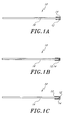
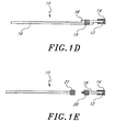
Figures 1A 1B, 1C, 1D, and 1E schematically illustrate various embodiments of a
concentration monitor compatible with embodiments of the present invention and which
comprise a carrier, a chemical substance, and a temperature probe.
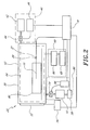
Figure 2 schematically illustrates a sterilization system compatible with
embodiments of the present invention.
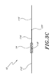
Figures 3A, 3B, 3C, 3D, and 3E schematically illustrate various embodiments of a
concentration monitor comprising a reference temperature probe compatible with
embodiments of the present invention.
Figure 4A schematically illustrates a concentration monitor comprising an
integrated circuit chip compatible with embodiments of the present invention.
Figure 4B schematically illustrates a concentration monitor comprising
thermocouple junctions comprising thin conductive films compatible with embodiments
of the present invention.
Detailed Description of the Preferred Embodiment
Figures 1A, 1B, 1C, 1D, and 1E illustrate embodiments of a concentration
monitor 10 compatible with embodiments of the present invention. In certain
embodiments of the present invention, a concentration monitor 10 comprises a carrier 12,
a chemical substance 14, and a temperature probe 16. All of the elements of the
concentration monitor 10 must be compatible with its operating conditions.
Concentration monitors 10 compatible with the present invention can operate under a
wide range of pressures, such as atmospheric pressures or sub-atmospheric pressures (i.e.,
vacuum pressures). For use in a sterilization system utilizing hydrogen peroxide vapor
with or without plasma, the carrier 12, chemical substance 14, and temperature probe 16
must all be compatible with operations under sterilization conditions and with exposure
to hydrogen peroxide vapor and plasma. Persons skilled in the art recognize that there is
a wide variety of materials and structures which can be selected as the carrier 12 in these
embodiments. The carrier 12 couples the chemical substance 14 in close proximity to the
temperature probe 16 so as to minimize the thermal losses between them. Examples of
adequate carriers include, but are not limited to, acrylic, epoxy, nylons, polyurethane,
polyhydroxyethylenemethacrylate (polyHEMA), polymethylmethacrylate (PMMA), polyvinylpyrrolidone
(PVP), polyvinylalcohol (PVA), silicone, tape, or vacuum grease.
Additionally, the carrier 12 can either be configured to expose the chemical substance 14
directly to the environment, or to enclose the chemical substance 14 in a gas permeable
pouch, such as Tyvek tubing, or a gas impermeable enclosure with a hole or holes. In
certain embodiments, the chemical substance 14 can be coupled directly to the
temperature probe 16 without use of a carrier. For example, the chemical substance 14
can be formed as an integral part of the temperature probe 16 or, if the chemical
substance 14 is sufficiently adhesive, it can be directly coupled to the temperature probe
16. Chemical vapor deposition or electrochemical plating can also be used to couple the
chemical substance 14 directly to the temperature probe 16.
The chemical substance 14 undergoes an exothermic reaction with the oxidative
gas or vapor to be monitored, producing a detectable amount of thermal energy (i.e., heat)
upon exposure to the oxidative gas or vapor to be monitored. Persons skilled in the art
are able to choose an appropriate chemical substance 14 which yields a sufficient amount
of heat upon exposure to the relevant range of concentrations of the oxidative gas or
vapor to be measured. Examples of chemical substances 14 for use in a hydrogen
peroxide sterilization system include, but are not limited to, substances that catalytically
decompose hydrogen peroxide, substances that are easily oxidized by hydrogen peroxide,
and substances that contain hydroxyl functional groups. Substances that catalytically
decompose hydrogen peroxide include, but are not limited to, catalase, copper and copper
alloys, iron, silver, platinum, and palladium. Substances that are easily oxidized by
hydrogen peroxide include, but are not limited to, magnesium chloride (MgCl2), iron (II)
compounds such as iron (II) acetate, potassium iodide (KI), sodium thiosulfate, and
sulfides and disulfides such as molybdenum disulfide, 1,2-ethanedithiol, methyl disulfide,
cysteine, methionine, and polysulfides. Substances that contain hydroxyl functional
groups include, but are not limited to, polyethylene glycol (PEG), polyethylene oxide
(PEO), and polyvinyl alcohol (PVA). These substances can be in the form of polymers
that comprise hydroxyl functional groups, and persons skilled in the art appreciate that
such polymers can also be co-polymers. In addition, a combination of these above-described
substances may be chosen as the chemical substance 14. Furthermore, persons
skilled in the art are able to select the appropriate amount of chemical substance 14 to
yield a sufficient amount of heat upon exposure to the relevant range of hydrogen
peroxide concentrations.
Various configurations compatible with use with embodiments of the present
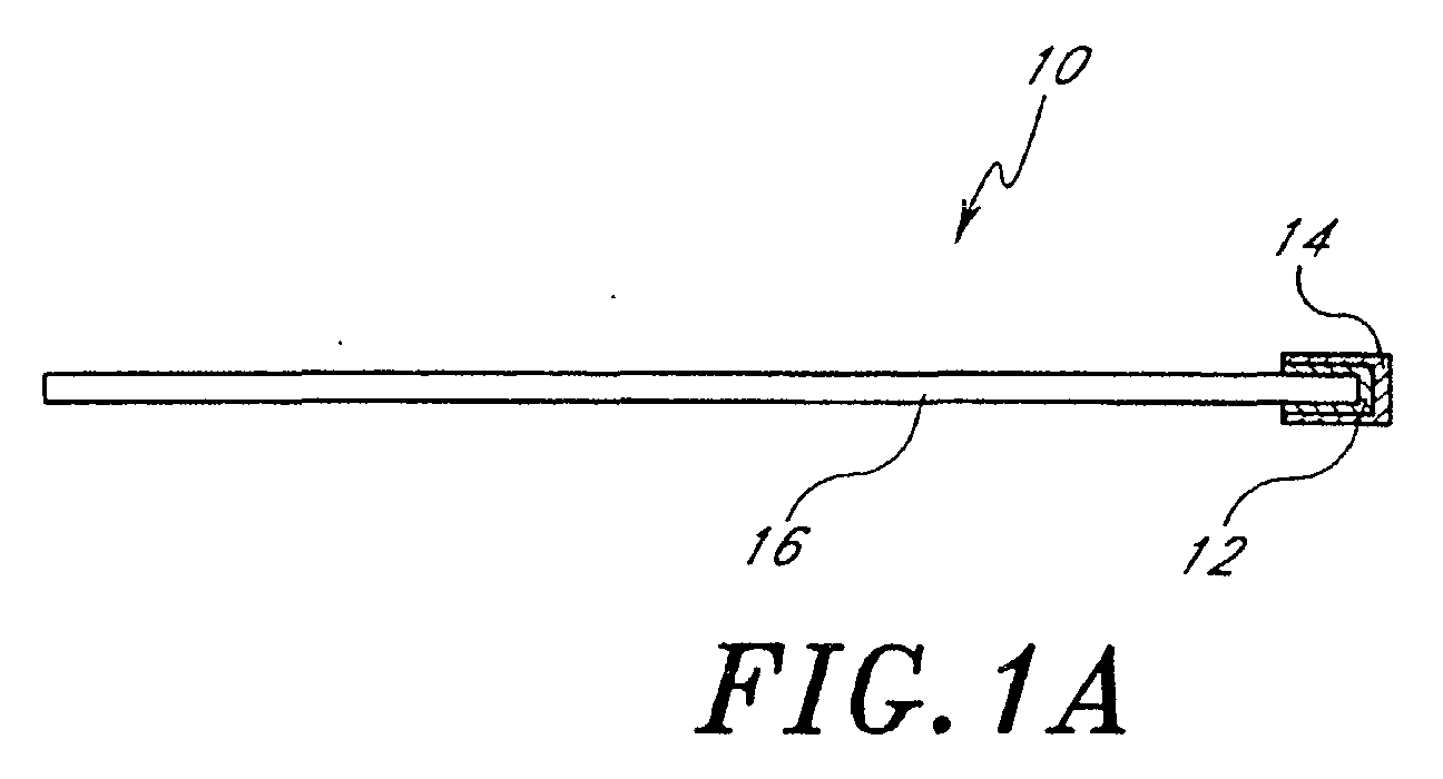
invention are illustrated in Figures 1A, 1B, 1C, 1D, and 1E. Figure 1A shows a
temperature probe 16 coated with a thin layer of carrier 12 on the tip of the probe 16 and
the chemical substance 14 is coated on the outside of the carrier 12. Figure 1B shows the
chemical substance 14 is mixed with the carrier 12 and applied onto the tip of the
temperature probe 16. For example, a chemical substance 14 such as PEG is mixed with
a carrier 12 such as acrylic binder in an aqueous suspension, then coated onto a
temperature probe 16. The chemical substance 14 is accessible for reaction as the
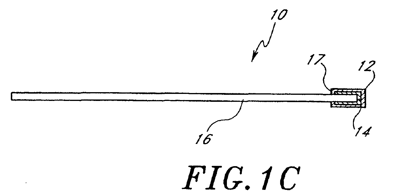
hydrogen peroxide diffuses into the carrier. Figure 1C show the chemical substance 14 is
enclosed onto the tip of the temperature probe 16 with a carrier 12. The carrier 12 is a
gas-permeable pouch with a heat-sealed area 17, which typically is composed of a
nonwoven polyolefin material, such as Tyvek® (nonwoven polyethelene) sold by E.I. du
Pont de Nemours and Co. of Wilmington, Delaware or CSR (central supply room)
wrapping material (nonwoven polypropylene) sold by Kimberly-Clark Corp. of Dallas,
Texas. The carrier 12 can also be a gas-impermeable pouch or other enclosure with one
or more holes to allow the diffusion of gas or vapor to react with the chemical substance
14 retained in the enclosure. Figure 1D shows a chemical substance 14 coupled to a heat-conducting
material 18 with a carrier 12, and the heat-conducting material 18 is coupled
to the temperature probe 16 with a substrate 19. The substrate 19 can be tape, adhesive,
or any other coupling means. The heat-conducting material 18 can be metallic wire or
any other materials which can properly conduct heat to the temperature probe 16. Figure
1E shows a chemical substance 14 coupled to a temperature probe 16 with a carrier 12,
and two parts of the temperature probe 16 can be connected and disconnected with a male
connector 20 and a female connector 21.
The temperature probe 16 is a device which measures the temperature at a
particular location. One embodiment of the present invention utilizes a fiberoptic
temperature probe, such as a Luxtron® 3100 fluoroptic thermometer, as the temperature
probe 16. This fiberoptic temperature probe 16 is coated with Teflon and therefore is
very compatible to any oxidative gas or vapor. Another embodiment utilizes a
temperature probe 16 which is a thermocouple probe which utilizes a junction of two
metals or alloys. The thermocouple junction produces a voltage which is a known
function of the junction's temperature. Measurements of this voltage across the
thermocouple junction can therefore be converted into measurements of the junction's
temperature. Thermocouple junctions can be made quite small (e.g., by spot welding
together two wires of 0.025-millimeter diameter composed of differing alloys), so they
can be positioned into size-restricted volumes. In yet other embodiments, the
temperature probe 16 can be a thermistor, glass thermometer, resistance temperature
detector (RTD) probe, temperature strip, optical temperature sensor, or infrared
temperature sensor.
Table 1 illustrates the increases of temperature measured by a
concentration
monitor 10 with potassium iodide (KI) as the
chemical substance 14. The tip of the
fiberoptic temperature probe was first coated with a thin layer of Dow Corning high
vacuum grease (part number 2021846-0888). About 0.15 grams of KI powder was then
applied onto the vacuum grease. This configuration is the same as illustrated in Figure
1A. The measurements were conducted by suspending the concentration monitor
10 in a
vacuum chamber heated to 45 °C, evacuating the chamber, recording the initial probe
temperature, injecting hydrogen peroxide into the chamber, recording the temperature
after all hydrogen peroxide was vaporized, evacuating the chamber to remove the
hydrogen peroxide, and venting the chamber. The measurements were repeated with
different concentrations of hydrogen peroxide injected into the chamber. The
same
temperature probe 16 was reused for all the measurements, and the results are shown in
Table 1. As can be seen from Table 1, KI produces a measurable increase of temperature
with increasing concentration of hydrogen peroxide. Additionally, this concentration
monitor
10 can be reused many times.
| Concentration of H2O2 (mg/L) | Temperature increase (°C) |
| 0.2 | 3.0 |
| 0.4 | 8.3 |
| 0.8 | 19.2 |
| 1.3 | 24.2 |
| 2.1 | 33.7 |
Table 2 provides data on the measured temperature increases with varying
concentrations of hydrogen peroxide for a
concentration monitor 10 utilizing
different
chemical substances 14. Same test conditions and probe configurations were used in
these temperature measurements. As can be seen from Table 2, each of the
chemical
substances 14 produced a measurable temperature rise which increased with increasing
hydrogen peroxide concentration.
| Chemical substance | Temperature increase (°C) |
| | 0.4 mg/L | 1.0 mg/L | 2.1 mg/L |
| Platinum on Alumina | 13.5 | 17.2 | --- |
| Catalase | 1.1 | --- | 6.9 |
| Iron (II) acetate | 62.5 | 83.1 | --- |
| Magnesium Chloride | 0.8 | --- | 4.4 |
The utility of using a thermocouple junction as the
temperature probe 16 is
illustrated in Table 3. For these measurements, the concentration monitor
10 was
configured as illustrated in Figure 1A. The test conditions of Table 1 were also used for
these measurements. Table 3 illustrates that significant temperature increases were also
observed using a
thermocouple temperature probe 16.
| Concentration of H2O2 (mg/L) | Temperature increase (°C) |
| 0.2 | 2.7 |
| 0.4 | 11.9 |
| 0.8 | 19.3 |
| 2.1 | 24.2 |
The utility of using double-sided tape as the
carrier 12 is illustrated by Table 4,
which presents the temperature increases measured by a
fiberoptic temperature probe 16.
A thin layer of 3M Scotch double-sided tape was first applied to the tip of the
fiberoptic
probe 16. About 0.15 grams of KI powder was then coated onto the tape. Table 1 test
conditions were repeated for these measurements. It is apparent from Table 4 that
measurable increases of temperature were detected for increasing H
2O
2 concentration
when using double-sided tape as the
carrier 12.
| Concentration of H2O2 (mg/L) | Temperature increase (°C) |
| 0.4 | 9.3 |
| 1 | 16.8 |
| 2.1 | 31.2 |
The utility of using epoxy as the
carrier 12 is illustrated by Table 5, which
presents the temperature increases measured by a
fiberoptic temperature probe 16. The
concentration monitor
10 was constructed by applying a thin layer of Cole-Palmer 8778
epoxy on an aluminum wire. About 0.15 grams of KI powder was then applied and dried
onto the epoxy. Finally, the aluminum wire was attached to the
temperature probe 16.
Table 1 test conditions were repeated for these measurements. It is apparent that
measurable increases of temperature were detected for increasing H
2O
2 concentration
when using epoxy as the
carrier 12.
| Concentration of H2O2 (mg/L) | Temperature increase (°C) |
| 0.4 | 7.8 |
| 1 | 12.9 |
| 2.1 | 20.1 |
The utility of using an enclosure as the
carrier 12 to enclose the
chemical
substance 14 is illustrated by Tables 6 and 7, which illustrate the increase of temperature
detected by a
fiberoptic temperature probe 16 with KI contained in an enclosure. For
Table 6, the enclosure was PVC shrink tubing with holes. The holes were small enough
to trap the KI powder but large enough to allow the diffusion of gas or vapor into the
PVC tubing. For Table 7, the enclosure was gas-permeable Tyvek tubing fabricated from
heat-sealed 1073B Tyvek. The inner diameter of the enclosure was about 0.5
centimeters, and its length was approximately 1.5 centimeters. For Table 6, about 0.2
grams of KI powder was enclosed in the PVC tubing and the concentration monitor
10
was re-used for all measurements. For Table 7, about 0.2 grams of KI powder was
enclosed in the Tyvek pouch and the concentration monitor
10 was also re-used for all
measurements. Table 1 test conditions were used for these measurements. It is apparent
that measurable increases of temperature were detected for increasing H
2O
2 concentration
when using both embodiments of a gas-permeable pouch as the
carrier 12. The results
also demonstrate that the concentration monitor
10 can be re-used and the measurements
are reproducible.
Concentration of
H2O2 (mg/L) | Temperature increase (°C) |
| | Trial #1 | Trial #2 | Average |
| 0.2 | 1.1 | 1.1 | 1.1 |
| 0.4 | 9.5 | 8.8 | 9.2 |
| 1.0 | 13.6 | 13.6 | 13.6 |
Concentration of
H2O2 (mg/L) | Temperature increase (°C) |
| | Trial #1 | Trial #2 | Average |
| 0.4 | 9.7 | 8.4 | 9.1 |
| 1.0 | 17.3 | 16.8 | 17.1 |
| 1.4 | 23.6 | 23.6 | 23.6 |
A chemical substance 14 comprising a polymer comprising hydroxyl functional
groups may also be used to fabricate a hydrogen peroxide monitor. For example,
polyethylene glycol or PEG, with a formulation of H(OCH2CH2)nOH, mixed with an
acrylic binder in aqueous suspension provides a hydrogen peroxide monitor compatible
with the present invention. Such chemical substances have a high specificity to oxidative
gas or vapor, such as H2O2, and essentially no sensitivity to H2O. Persons skilled in the
art appreciate that other polymers containing hydroxyl functional groups are also
compatible with the present invention.
To examine the utility of a PEG/acrylic suspension, various H2O2 monitors were
fabricated using the following procedure. A 1:1 ratio by weight PEG/acrylic mixture was
made by mixing and stirring 5 g of acrylic binder (Vivitone, Inc., product number 37-14125-001,
metallic binder LNG) with 5 g of PEG (Aldrich, Inc., product number 30902-8,
molecular weight of approximately 10,000) in a 20-g scintillation vial. Other
embodiments compatible with the present invention can utilize ratios other than 1:1. The
mixture was then heated to approximately 75 °C and stirred thoroughly. After allowing
the mixture to cool to room temperature, the vial containing the suspension was capped
and stored in a cool, dark environment.
To fabricate each H2O2 monitor, the metal surface of a thermocouple was
chemically treated to improve the adhesion of the chemical substance 14 to the carrier 12.
The thermocouple was soaked in isopropyl alcohol for approximately two minutes and its
end was brushed lightly to remove debris. After air-drying for approximately five
minutes, the end of the thermocouple was soaked in approximately 10-20% by volume
sulfuric acid (H2SO4) for approximately two minutes, then rinsed thoroughly in generous
amounts of deionized water. The thermocouple was then dried in an oven at
approximately 55 °C for approximately five minutes, then allowed to cool to room
temperature outside the oven for approximately five minutes. The end of the
thermocouple was then coated with the PEG/acrylic mixture by dipping the end of the
thermocouple into the vial containing the mixture. Note that in order to produce a thicker
overall coating, the end of the thermocouple can be dipped repeatedly. The thermocouple
was then returned to the oven to dry at approximately 55 °C for approximately five
minutes. A similar procedure was used to fabricate PEO/acrylic H2O2 monitors.
The above procedure can generate H2O2 monitors which are durable, inexpensive,
and easy to manufacture. Also, PEG/acrylic mixtures have a relatively long shelf life of
more than approximately three years. By utilizing a coating of the PEG/acrylic
suspension, very small and flexible H2O2 monitors can be fabricated with different sizes
and shapes. For example, if it is desirable to measure the H2O2 concentration within a
narrow tube, the reactive chemical substance can be coated onto an optical fiber such as a
Luxtron® fluoroptic temperature probe, a fiberoptic temperature probe, or on a metal
wire of a thermistor or thermocouple assembly.
PEG/acrylic H
2O
2 monitors and PEO/acrylic H
2O
2 monitors fabricated by the
above procedure were tested in a
STERRAD® 100 low temperature, hydrogen peroxide
gas plasma sterilization system. The sensitivity of these H
2O
2 monitors to hydrogen
peroxide vapor is illustrated in Table 8 which provides the measured temperature
increases in °C generated by the H
2O
2 monitors for different concentrations of H
2O
2 in
the STERRAD® chamber. The change of temperature is referenced to the temperature
read by the thermocouple just prior to the injection of H
2O
2.
| | Temperature Increase (°C) |
| H2O2 (mg/L) | PEG/acrylic | PEO/acrylic |
| 0.41 | 2.6 | 2.0 |
| 0.77 | 3.4 | 3.5 |
| 1.45 | 5.8 | 5.6 |
| 2.87 | 9.4 | 9.7 |
| 5.73 | 16.1 | 14.0 |
| 11.5 | 24.2 | 22.0 |
Measured temperature increases for known H2O2 concentrations can be used to
generate a calibration curve for such H2O2 monitors. The H2O2 responses of individual
H2O2 monitors using the same chemical substance/carrier mixture were substantially
similar to one another, indicating that H2O2 monitors with reproducible responses to
H2O2 can be produced. For sufficient reproducibility among the H2O2 monitors using the
same chemical substance/carrier mixture, a standard response equation can express the
response for all such H2O2 monitors, thereby eliminating the need for individual
calibration of the H2O2 monitors to convert the temperature change into a measurement
of the H2O2 concentration.
H2O2 monitors compatible with the present invention with a reactive chemical
substance/carrier such as the PEG/acrylic mixture can utilize other temperature probes 16
besides thermocouples. Appropriate temperature probes 16 include, but are not limited
to, glass thermometers, thermocouples, thermistors, RTD probes, temperature strips,
optical temperature sensors, and infrared temperature sensors. In addition, the sensing
surface of the temperature probe 16 can be chemically or mechanically etched to improve
the adhesion between the reactive chemical substance 14 and the temperature probe 16.
The reactive chemical substance 14 can be coated onto the temperature sensitive surface
of the temperature probe 16 by a variety of methods, including but not limited to,
dipping, painting, spraying, chemical vapor deposition, or electrochemical plating. For
faster response times, it is preferable to apply a thin coat of the reactive chemical
substance 14 on the temperature probe 16 with low thermal mass. The thickness of the
coating can also be controlled by adjusting the dwelling time or the speed of withdrawal
of the probe 16 from the solution as it is being coated, and the viscosity of the reactive
chemical substance 14. Additional layers of the reactive chemical substance 14 can be
added to the initial coating to improve signal strength and/or sensitivity.
Figure 2 schematically illustrates a sterilization system 25 utilizing one
embodiment of the present invention. The sterilization system 25 has a vacuum chamber
30 with a door 32 through which items to be sterilized are entered into and removed from
the chamber 30. The door is operated by utilizing a door controller 34. The vacuum
chamber 30 also has a gas inlet system 40, a gas outlet system 50, and a radio-frequency
(rf) system 60. Other embodiments compatible with the present invention can utilize a
low frequency plasma sterilization system, such as that described in "Sterilization System
Employing Low Frequency Plasma", U.S. Patent Application No. 09/676,919, which is
incorporated by reference herein. Comprising the gas inlet system 40 is a source of
hydrogen peroxide (H2O2) 42, a valve 44, and a valve controller 46. The gas outlet
system 50 comprises a vacuum pumping system 52, a valve 54, a valve controller 56, and
a vacuum pumping system controller 58. In order to apply radio-frequency energy to the
H2O2 in the vacuum chamber 30, the rf system 60 comprises a ground electrode 62, a
powered electrode 64, a power source 66, and a power controller 68. The sterilization
system 25 is operated by utilizing a control system 70 which receives input from the
operator, and sends signals to the door controller 34, valve controllers 46 and 56, vacuum
pumping system controller 58, and power controller 68. Coupled to the control system
70 (e.g., a microprocessor) is the concentration monitor 10, which sends signals to the
control system 70 which are converted into information about the H2O2 concentration in
the vacuum chamber 30 at the location of the concentration monitor 10. The sterilized
article 80 is shown to be positioned in the chamber 30 with concentration monitor 10
located in the load region to monitor the concentration of hydrogen peroxide in the load
region. Persons skilled in the art are able to select the appropriate devices to adequately
practice the present invention.
The heat produced between the oxidative gas or vapor and the chemical substance
14 may not be the same for different configurations of the concentration monitor 10,
carrier 12, and chemical substance 14. Therefore, for a given type of concentration
monitor 10, a calibration curve needs to be established to determine the relationship
between the concentration of oxidative gas or vapor and the heat produced. Once the
calibration curve is established, the heat detected during the measurement can be
converted to the concentration of the oxidative gas or vapor around the monitor 10.
By coupling the operation of the sterilization system 25 with the H2O2
concentration measured by the concentration monitor 10, the sterilization system 25 is
assured of operating with an appropriate amount of H2O2 in the region of the articles to be
sterilized. First, if the H2O2 concentration is determined to be too low for adequate
sterilization, the control system 70 can signal the inlet valve controller 46 to open the
inlet valve 44, thereby permitting more H2O2 into the chamber 30. Alternatively, if the
H2O2 concentration is determined to be too high, the control system 70 can signal the
outlet valve controller 56 to open the outlet valve 54, thereby permitting the vacuum
pumping system 52 to remove some H2O2 from the chamber 30. Furthermore, if the
sterilization system is being operated in a dynamic pumping mode (i.e., H2O2 is
introduced into the chamber 30 via the inlet valve 44 while at the same time, it is pumped
out via the outlet valve 54), then either the inlet valve 44 or the outlet valve 54, or both
can be adjusted in response to the measured H2O2 concentration to ensure an appropriate
level of H2O2.
Because the concentration monitor 10 provides localized information regarding
the H2O2 concentration, it is important to correctly position the concentration monitor 10
within the sterilization chamber 30. In some embodiments, the concentration monitor 10
is fixed to a particular position within the sterilization chamber 30 in proximity to the
position of the sterilized articles 80. In other embodiments, the concentration monitor 10
is not fixed to any particular position within the sterilization chamber 30, but is placed on
or near the sterilized article 80 itself. In this way, the concentration monitor 10 can be
used to measure the H2O2 concentration to which the sterilized article 80 is exposed. In
particular, if the sterilized article 80 has a region which is exposed to a reduced
concentration of H2O2 due to occlusion or a reduced opening, then the concentration
monitor 10 can be placed within this region to ensure that a sufficient H2O2 concentration
is maintained to sterilize this region. The small size of the concentration monitor of the
present invention permits the concentration monitor to be placed in very restricted
volumes, such as the inner volume of a lumen, or in a container or wrapped tray. In still
other embodiments of the present invention, a plurality of concentration monitors 10 can
be utilized to measure the H2O2 concentration at various positions of interest.
The temperature of the temperature probe 16 within the sterilization chamber 30
may fluctuate due to other factors unrelated to the hydrogen peroxide concentration.
These non-H2O2-related temperature fluctuations may be misconstrued as resulting from
changes of the H2O2 concentration in the sterilization chamber 30, and may result in
measurement errors. In certain embodiments, as schematically illustrated in Figure 3A, a
reference temperature probe 90 can be utilized in conjunction with the temperature probe
16 of the concentration monitor 10 to provide a measure of the ambient temperature
within the sterilization chamber 30 to improve the performance of the concentration
monitor 10.
The reference temperature probe 90 in proximity to the temperature probe 16 can
then be used to measure the non-H2O2-related temperature fluctuations and compensate
for these non-H2O2-related temperature fluctuations from the temperature reading of the
temperature probe 16. In certain embodiments, the non-H2O2-related temperature
fluctuations are monitored substantially simultaneously with the temperature readings of
the temperature probe 16. Typically, the reference temperature probe 90 is substantially
identical to the temperature probe 16, but does not comprise the reactive chemical
substance 14. For example, a PEG/acrylic H2O2 concentration monitor 10 can comprise a
reference temperature probe 90 with the acrylic binder but without the PEG polymer.
Alternatively, the H2O2 concentration monitor 10 can comprise a bare reference
temperature probe 90 without the binder or the reactive chemical substance 14.
In the embodiment schematically illustrated in Figure 3A, the concentration
monitor 10 comprises a reference temperature probe 90 and a temperature probe 16, the
reference temperature probe 90 separate from the temperature probe 16. In certain such
embodiments, the concentration monitor 10 comprises a microprocessor 100, and the
temperature probe 16 and the reference temperature probe 90 are each coupled to a
separate data acquisition channel 102, 104 of the microprocessor 100. The
microprocessor 100 can comprise an algorithm, in hardware, software, or both, which
subtracts the ambient temperature, as determined by the reference temperature probe 90,
from the temperature detected by the temperature probe 16 to arrive at the temperature
rise due to the oxidative gas or vapor concentration in the sterilization chamber 30. In
such embodiments, electrical connections between the temperature probe 16, reference
temperature probe 90, and microprocessor 100 require two data acquisition channels
which, in certain embodiments, are too large in size to allow the temperature probe 16
and reference temperature probe 90 to be placed in certain narrow lumens.
In certain embodiments, as schematically illustrated in Figure 3B, the
concentration monitor 10 comprises a first thermocouple junction 110 and a chemical
substance 14 coupled to the first thermocouple junction 110. The chemical substance 14
is reactive with the oxidative gas or vapor to produce heat. The first thermocouple
junction 110 comprises a first conductor 112 and a second conductor 114 coupled to the
first conductor 112, the second conductor 114 being different from the first conductor
112.
The concentration monitor 10 further comprises a second thermocouple junction
120 which, in certain embodiments, is substantially similar to the first thermocouple
junction 110. The second thermocouple junction 120 is coupled in series to the first
thermocouple junction 110. In certain embodiments, as schematically illustrated in
Figure 3B, the second thermocouple junction 120 comprises a third conductor 116 and
the second conductor 114, the third conductor 116 coupled to the second conductor 114.
In embodiments in which the second thermocouple junction 120 is substantially similar to
the first thermocouple junction 110, the third conductor 116 is substantially similar to the
first conductor 112. For example, the first conductor 112 and third conductor 116 can
comprise constantan (copper-nickel alloy) wire and the second conductor 114 can
comprise iron wire, thereby forming two J-type thermocouple junctions in series.
Typically, such thermocouple junctions have sensitivities on the order of µV/°C. The
first and second thermocouple junctions 110, 120 are substantially thermally isolated
from one another, but are placed in the same diffusion-restricted region as one another.
Placed in an environment with no oxidative gas or vapor, the first thermocouple
junction 110 and second thermocouple junction 120 each generates a voltage indicative
of the ambient temperature. In embodiments in which the second thermocouple junction
120 is substantially similar to the first thermocouple junction 110, both thermocouple
junctions 110, 120 generate the same voltage but are oriented to have opposite polarity
such that the net voltage across both the first thermocouple junction 110 and the second
thermocouple junction 120 is zero. Such a concentration monitor 10 in an environment
with no oxidative gas or vapor responds to temperature fluctuations by maintaining a zero
net voltage across the two thermocouple junctions 110, 120.
Upon exposing the chemical substance 14 to the oxidative gas or vapor, the heat
generated by the chemical substance 14 increases the temperature of the first
thermocouple junction 110 while the temperature of the second thermocouple junction
120 remains substantially unaffected, remaining at the ambient temperature. In
embodiments in which the second thermocouple junction 120 is substantially similar to
the first thermocouple junction 110, the voltage generated by the first thermocouple
junction 110 is different from the voltage generated by the second thermocouple junction
120 in the presence of the oxidative gas or vapor. The net voltage across the first and
second thermocouple junctions 110, 120 is responsive to the temperature difference
between the first thermocouple junction 110 with the chemical substance 14 and the
second thermocouple junction 120 without the chemical substance 14. Since any
temperature fluctuations not due to the oxidative gas or vapor concentration affect both
thermocouple junctions 110, 120 equally, the net voltage across both the first
thermocouple junction 110 and second thermocouple junction 120 then corresponds to
the concentration of the oxidative gas or vapor.
In certain embodiments, the first thermocouple junction 110 and second
thermocouple junction 120 are each formed by welding together two conductors
comprising different materials. Alternatively, one or both of the thermocouple junctions
110, 120 is formed by twisting together two conductors comprising different materials.
Other embodiments compatible with the present invention can form the first and second
thermocouple junctions 110, 120 by connecting the two conductors together using other
methods. As schematically illustrated in Figures 3A and 3B, the conductors of certain
embodiments are metal wires. The materials for the conductors which comprise the first
thermocouple junction 110 and second thermocouple junction 120 are selected to provide
thermocouple junctions with sufficient thermoelectric sensitivity and generally low cost,
high electrical conductivity, low thermal conductivity, and good material compatibility
with the sterilization process.
As schematically illustrated in Figure 3C, in certain embodiments, the
concentration monitor 10 has a linear configuration and comprises a first thermocouple
junction 110 and a second thermocouple junction 120. The first thermocouple junction
110 is formed by coupling a first conductor 112 to a second conductor 114 such that the
first conductor 112 and second conductor 114 are substantially colinear. The second
thermocouple junction 120 is formed by coupling the second conductor 114 to a third
conductor 116 such that the second conductor 114 and third conductor 116 are also
substantially colinear. The first thermocouple junction 110 is coupled to the chemical
substance 14 and the second thermocouple junction 120 is not coupled to the chemical
substance 14. Such an embodiment is especially useful for monitoring the concentration
of the oxidative gas or vapor within a long, narrow lumen. Similarly, in the embodiment
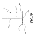
schematically illustrated in Figure 3D, the concentration monitor 10 has a "T"
configuration. Other configurations are compatible with embodiments of the present
invention, and the particular embodiment utilized can be designed for compatibility with
the region in which the oxidative gas or vapor concentration is to be measured.
As schematically illustrated in Figure 3E, in certain embodiments, the
concentration monitor 10 comprises a first connector 130, second connector 132, cable
134, data acquisition channel 136, and microprocessor 138. The first connector 130 and
second connector 132 can be coupled together to electrically connect the first conductor
112 and third conductor 116 via the cable 134 to the data acquisition channel 136 of the
microprocessor 138. The first connector 130 and second connector 132 can also be
decoupled so that, for example, the concentration monitor 10 can be repositioned at a
different location within the sterilization chamber.
The embodiments schematically illustrated in Figures 3B-3E provide advantages
over the embodiment schematically illustrated in Figure 3A. First, using two
thermocouple junctions 110, 120 in series requires only one sensing circuit or one data
acquisition channel to monitor the concentration of the oxidative gas or vapor, as
opposed to two data acquisition channels as in Figure 3A. Besides providing a potential
cost savings, using only one data acquisition channel or sensing circuit eliminates the
potential effects of variations between the multiple channels or sensing circuits. Second,
since the net voltage across the two thermocouple junctions 110, 120 represents a
temperature difference rather than an absolute temperature, the dynamic range of values
is smaller, so the an analog-to-digital converter with a given number of bits can thereby
provide greater precision when used in the chemical concentration measuring system.
Third, because only one pair of conductors is needed to detect the net voltage across the
two thermocouple junctions 110, 120, the size of the concentration monitor 10 can be
made smaller to fit into various diffusion-restricted environments, such as narrow
lumens.
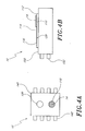
As schematically illustrated in Figure 4A, in certain embodiments, the
concentration monitor 10 comprises an integrated circuit chip 140 which comprises
circuitry which includes the first and second thermocouple junctions 110, 120, chemical
substance 14, and a microprocessor or other sensing circuit (not shown). The integrated
circuit chip 140 is configured to output a signal on one or more of its pins 142 to
communicate the measured concentration to the rest of the chemical concentration
measuring system. In certain embodiments, standard lithographic techniques can be used
to fabricate the first and second thermocouple junctions 110, 120 by depositing and
etching overlapping metal layers with different materials onto a substrate. Persons skilled
in the art are able to fabricate such concentration monitors 10 in accordance with
embodiments of the present invention.
As schematically illustrated in Figure 4B, in certain embodiments, the first and
second thermocouple junctions 110, 120 are formed from a first conductor 112, second
conductor 114, and third conductor 116, where one or more of the conductors comprises
a thin conductive film configuration. The chemical substance 14 is coupled to the first
thermocouple junction 110, and in certain embodiments, can also have a thin film
configuration. In embodiments in which first and second thermocouple junctions 110,
120 formed by thin film conductors are part of a thin film concentration monitor 150, a
signal indicative of the measured concentration can be provided on one or more of the
pins 152. In certain embodiments, a thin film concentration monitor 150 may be
incorporated into the packaging of the articles to be sterilized, thereby providing localized
concentration information from a plurality of articles in the load.
In embodiments in which the first thermocouple junction 110 is substantially
similar to the second thermocouple junction 120, further advantages are achieved.
First, the concentration monitor 10 does not require an algorithm to correct for ambient
temperature, since the net voltage across the two thermocouple junctions due to ambient
temperature is null. Second, a cold junction compensation is not required, since ambient
temperature has effectively no contribution. Third, only a relatively small amount of the
second conductor 114 is needed to form the two thermocouple junctions, thereby
realizing a cost savings over other embodiments.
This invention may be embodied in other specific forms without departing from the
essential characteristics as described herein. The embodiments described above are to be
considered in all respects as illustrative only and not restrictive in any manner. The scope
of the invention is indicated by the following claims rather than by the foregoing
description. Any and all changes which come within the meaning and range of equivalency
of the claims are to be considered within their scope.