EP1308662A2 - Quick-acting disconnectable coupling for at least one tube - Google Patents
Quick-acting disconnectable coupling for at least one tube Download PDFInfo
- Publication number
- EP1308662A2 EP1308662A2 EP02356217A EP02356217A EP1308662A2 EP 1308662 A2 EP1308662 A2 EP 1308662A2 EP 02356217 A EP02356217 A EP 02356217A EP 02356217 A EP02356217 A EP 02356217A EP 1308662 A2 EP1308662 A2 EP 1308662A2
- Authority
- EP
- European Patent Office
- Prior art keywords
- tube
- ring
- window
- cap
- intended
- Prior art date
- Legal status (The legal status is an assumption and is not a legal conclusion. Google has not performed a legal analysis and makes no representation as to the accuracy of the status listed.)
- Granted
Links
Images


Classifications
-
- F—MECHANICAL ENGINEERING; LIGHTING; HEATING; WEAPONS; BLASTING
- F16—ENGINEERING ELEMENTS AND UNITS; GENERAL MEASURES FOR PRODUCING AND MAINTAINING EFFECTIVE FUNCTIONING OF MACHINES OR INSTALLATIONS; THERMAL INSULATION IN GENERAL
- F16L—PIPES; JOINTS OR FITTINGS FOR PIPES; SUPPORTS FOR PIPES, CABLES OR PROTECTIVE TUBING; MEANS FOR THERMAL INSULATION IN GENERAL
- F16L37/00—Couplings of the quick-acting type
- F16L37/08—Couplings of the quick-acting type in which the connection between abutting or axially overlapping ends is maintained by locking members
- F16L37/084—Couplings of the quick-acting type in which the connection between abutting or axially overlapping ends is maintained by locking members combined with automatic locking
- F16L37/092—Couplings of the quick-acting type in which the connection between abutting or axially overlapping ends is maintained by locking members combined with automatic locking by means of elements wedged between the pipe and the frusto-conical surface of the body of the connector
- F16L37/0925—Couplings of the quick-acting type in which the connection between abutting or axially overlapping ends is maintained by locking members combined with automatic locking by means of elements wedged between the pipe and the frusto-conical surface of the body of the connector with rings which bite into the wall of the pipe
-
- F—MECHANICAL ENGINEERING; LIGHTING; HEATING; WEAPONS; BLASTING
- F16—ENGINEERING ELEMENTS AND UNITS; GENERAL MEASURES FOR PRODUCING AND MAINTAINING EFFECTIVE FUNCTIONING OF MACHINES OR INSTALLATIONS; THERMAL INSULATION IN GENERAL
- F16L—PIPES; JOINTS OR FITTINGS FOR PIPES; SUPPORTS FOR PIPES, CABLES OR PROTECTIVE TUBING; MEANS FOR THERMAL INSULATION IN GENERAL
- F16L37/00—Couplings of the quick-acting type
- F16L37/08—Couplings of the quick-acting type in which the connection between abutting or axially overlapping ends is maintained by locking members
- F16L37/084—Couplings of the quick-acting type in which the connection between abutting or axially overlapping ends is maintained by locking members combined with automatic locking
- F16L37/092—Couplings of the quick-acting type in which the connection between abutting or axially overlapping ends is maintained by locking members combined with automatic locking by means of elements wedged between the pipe and the frusto-conical surface of the body of the connector
- F16L37/0926—Couplings of the quick-acting type in which the connection between abutting or axially overlapping ends is maintained by locking members combined with automatic locking by means of elements wedged between the pipe and the frusto-conical surface of the body of the connector with an inner support sleeve arranged within the pipe
-
- F—MECHANICAL ENGINEERING; LIGHTING; HEATING; WEAPONS; BLASTING
- F16—ENGINEERING ELEMENTS AND UNITS; GENERAL MEASURES FOR PRODUCING AND MAINTAINING EFFECTIVE FUNCTIONING OF MACHINES OR INSTALLATIONS; THERMAL INSULATION IN GENERAL
- F16L—PIPES; JOINTS OR FITTINGS FOR PIPES; SUPPORTS FOR PIPES, CABLES OR PROTECTIVE TUBING; MEANS FOR THERMAL INSULATION IN GENERAL
- F16L2201/00—Special arrangements for pipe couplings
- F16L2201/10—Indicators for correct coupling
Abstract
Description
La présente invention a pour objet un raccord instantané démontable pour au moins un tube, notamment un tube en matériau thermoplastique ou en matériau composite, comprenant une âme métallique, par exemple en aluminium, revêtue de couches de matière synthétique. Ce raccord sert à réaliser la liaison entre plusieurs tubes ou entre un tube et un appareil, tel qu'un robinet ou un collecteur. Il s'agit de raccord pour des tubes servant notamment au transport de fluides domestiques.The present invention relates to an instant connection removable for at least one tube, in particular a tube made of material thermoplastic or composite material, comprising a core metallic, for example aluminum, coated with layers of synthetic. This connection is used to make the connection between several tubes or between a tube and a device, such as a tap or a manifold. It is connection for tubes used in particular for conveying fluids servants.
Les raccords instantanés pour tubes sont connus de longue date.Instant tube fittings are known from long dated.
Un tel raccord est connu par le document EP 0 021 795. Dans le raccord décrit dans ce document, chaque tube est inséré dans le raccord, l'étanchéité étant réalisée par un joint torique à l'extérieur du tube, et la retenue étant réalisée à l'aide d'une bague en matière synthétique présentant des bras radiaux équipés de griffes faisant saille vers l'intérieur.Such a connection is known from EP 0 021 795. In the fitting described in this document, each tube is inserted into the connection, the sealing being achieved by an O-ring outside the tube, and the restraint being made using a ring material synthetic with radial arms equipped with claws towards the inside.
Un tel raccord présente un certain nombre d'inconvénients ; le joint torique n'étant pas maintenu dans une gorge, il existe des risques de déplacement du tube et du joint à la façon d'un piston lors de pression cyclique du fluide ou de coups de bélier.Such a connection has a number of disadvantages; the O-ring not being held in a groove, there are risks of displacement of the tube and the seal in the manner of a piston during pressure cyclic fluid or water hammer.
Le guidage de la bague de retenue est de mauvaise qualité car elle est encliquetée dans un logement réalisé dans le corps du raccord, avec un jeu important. Enfin, dans le cas d'un raccordement avec un tube de matière synthétique ou composite, les griffes de la bague de retenue du tube risquent de rester planté dans la matière et de rendre le raccord difficilement démontable.The guide of the retaining ring is of poor quality because it is snapped into a housing made in the fitting body, with a big game. Finally, in the case of a connection with a tube of synthetic or composite material, the claws of the retaining ring of the tube may remain planted in the material and make the connection difficult to dismantle.
Le document WO 9607048 concerne un raccord comportant un joint et une bague d'accrochage situés à l'extérieur du tube. Il faut noter que dans ce raccord la bague d'accrochage vient comprimer axialement le joint d'étanchéité, ce phénomène pouvant être aggravé dans la mesure où la bague d'accrochage est entraínée par le tube pendant la connexion. Or cette compression axiale du joint d'étanchéité rend difficile l'introduction du tube dans le raccord.WO 9607048 relates to a coupling comprising a seal and an attachment ring located outside the tube. It should be noted that in this connection the snap ring compresses axially the seal, this phenomenon may be aggravated to the extent that the snap ring is driven by the tube during the connection. Gold this axial compression of the seal makes it difficult to introduce tube in the fitting.
Le but de l'invention est de fournir un raccord instantané permettant un démontage du tube, qui soit réalisé de façon compacte et simple en comportant un faible nombre de composants, et qui soit économique à réaliser.The object of the invention is to provide an instant connection allowing a disassembly of the tube, which is made compact and simple by having a small number of components, and which is economic to achieve.
Il est en effet important, lorsqu'une installation a été réalisée de permettre à l'installateur de démonter un raccord s'il a effectué une erreur. Il est également intéressant de pouvoir effectuer un montage à blanc, c'est-à-dire de positionner les tubes vis à vis des différents raccords auxquels ils sont destinés à être associés, sans que l'accrochage des tubes soit immédiatement réalisé.It is indeed important when an installation has been allow the installer to dismount a fitting if he made an error. It is also interesting to be able to do a blank edit, that is to say to position the tubes with respect to the different connections to which they are intended to be associated, without the hanging of the tubes be immediately realized.
A cet effet, le raccord qu'elle concerne comprend :
- un corps rigide comportant, pour le raccordement de chaque tube, une partie tubulaire de diamètre correspondant au diamètre intérieur du tube, dans laquelle est ménagée au moins une gorge périphérique servant de logement à un joint destiné à assurer l'étanchéité avec l'intérieur du tube, et une collerette destinée à servir de butée à l'extrémité du tube lors de l'introduction de celui-ci sur la partie tubulaire,
- une coiffe de diamètre intérieur correspondant au diamètre extérieur du tube, montée sur la partie tubulaire du corps et délimitant avec celle-ci une chambre servant au logement d'une bague d'accrochage du tube, contrainte vers la position d'accrochage lors d'un déplacement du tube dans le sens de dégagement hors du raccord, la coiffe présentant au niveau de chaque bague d'accrochage au moins une fenêtre permettant le passage d'un outil agissant sur la bague pour l'immobiliser axialement en position de manipulation du tube, c'est-à-dire lors du montage ou du démontage du tube, ou pour l'immobiliser en position montée, chaque bague d'accrochage comprenant en outre un corps cylindrique à partir duquel s'étendant axialement plusieurs dents séparées les unes des autres par des fentes, chaque dent comportant, à son extrémité libre, d'une part une face extérieure inclinée de l'extérieur vers l'intérieur et de l'arrière vers l'avant, destinée à coopérer avec une surface d'inclinaison complémentaire de la coiffe, et d'autre part, du côté intérieur, au moins une arête destinée à pénétrer dans la surface extérieure de la paroi du tube à raccorder, et le corps de la bague d'accrochage comporte un épaulement annulaire à partir duquel s'étendent vers l'arrière des plots destinés à venir prendre appui contre la collerette du corps.
- a rigid body comprising, for the connection of each tube, a tubular portion of diameter corresponding to the internal diameter of the tube, in which is provided at least one peripheral groove serving as a housing for a seal intended to seal with the interior of the tube, and a collar intended to serve as a stop at the end of the tube during the introduction thereof on the tubular part,
- a cap with an inside diameter corresponding to the outside diameter of the tube, mounted on the tubular portion of the body and delimiting therewith a chamber for accommodating a ring for fastening the tube, constrained towards the hooking position when a displacement of the tube in the direction of clearance out of the connection, the cap having at each attachment ring at least one window allowing the passage of a tool acting on the ring to immobilize it axially in the position of handling the tube , that is to say during assembly or disassembly of the tube, or to immobilize it in the mounted position, each attachment ring further comprising a cylindrical body from which axially extending a plurality of teeth separated from each other. other by slots, each tooth having, at its free end, on the one hand an external face inclined from the outside towards the inside and from the rear towards the front, intended to cooperate with a complementary tilt surface of the cap, and secondly, on the inner side, at least one edge intended to penetrate into the outer surface of the wall of the tube to be connected, and the body of the attachment ring comprises a shoulder annular from which extend towards the rear of the studs intended to bear against the collar of the body.
Après engagement d'un tube dans le raccord, entre le corps et la coiffe de celui-ci, l'accrochage est réalisé par la bague en exerçant une légère traction sur le tube, cette traction provoquant un resserrement de la bague qui immobilise axialement le tube dans le raccord. Pour procéder au démontage du raccord, le tube est repoussé vers l'intérieur du raccord jusqu'à ce que son extrémité vienne en butée à l'intérieur du raccord, un outil traversant une fenêtre ménagée dans la coiffe permettant alors d'immobiliser axialement la bague d'accrochage dans une position dans laquelle elle n'immobilise pas le tube, permettant ainsi le retrait de celui-ci.After engagement of a tube in the fitting, between the body and the cap of this one, the hanging is realized by the ring by exerting a slight pull on the tube, this traction causing a tightening of the ring that axially immobilizes the tube in the fitting. To proceed to disassembly of the fitting, the tube is pushed towards the inside of the fitting until its end comes into abutment inside the fitting, a tool through a window formed in the cap then allowing to axially immobilize the snap ring in a position in which it does not immobilize the tube, thus allowing the withdrawal thereof.
Lorsque après introduction du tube à l'intérieur du raccord, on exerce une traction sur le tube dans un sens de dégagement de celui-ci, la bague se déplace avec le tube, et les dents de la bague, contraintes radialement vers l'intérieur par appui contre la face intérieure de la coiffe, réalise un rapprochement des arêtes qui empêche tout retrait du tube hors du raccord.When after insertion of the tube into the fitting, pulls on the tube in a direction of disengagement thereof, the ring moves with the tube, and the teeth of the ring, constraints radially inwards by pressing against the inner face of the cap, achieves an approximation of the edges which prevents any withdrawal of the tube out fitting.
L'épaulement annulaire peut servir au blocage axial de la bague par un outil traversant une fenêtre.The annular shoulder can be used for axial locking of the ring by a tool through a window.
Selon une forme d'exécution de ce raccord, chaque fenêtre ménagée dans la coiffe s'étend axialement sensiblement depuis la collerette du corps jusqu'au-delà de l'épaulement de la bague d'accrochage, lorsque les plots de celle-ci sont en appui contre la collerette. L'épaulement de la bague se trouve donc dans la zone d'une fenêtre, en position reculée de la bague, ce qui permet, pour réaliser le démontage d'un tube, d'introduire un outil entre l'épaulement et le bord de la fenêtre situé du côté extérieur du raccord.According to one embodiment of this connection, each window formed in the cap extends axially substantially from the collar of the body up to the shoulder of the ring when the studs of the latter bear against the collar. The shoulder of the ring is therefore in the zone of a window, in the retracted position of the ring, which allows, to achieve the dismantling of a tube, introducing a tool between the shoulder and the edge of the window located on the outside of the fitting.
Selon une première possibilité, l'outil destiné à agir à travers une fenêtre sur la bague d'accrochage est un outil extérieur tel qu'un tournevis dont l'extrémité prend appui contre l'épaulement annulaire, pour agir sur la bague d'accrochage.According to a first possibility, the tool intended to act through a window on the snap ring is an external tool such as a screwdriver whose end bears against the annular shoulder, for act on the snap ring.
Selon une autre possibilité, l'outil destiné à agir à travers une fenêtre sur la bague d'accrochage est constitué par un cavalier destiné à venir entourer au moins partiellement la coiffe et comportant un doigt tourné vers l'intérieur, pénétrant dans une fenêtre pour s'engager entre l'épaulement de la bague d'accrochage et le bord de la fenêtre situé du côté de l'extrémité libre du raccord. Chaque cavalier étant réalisé en matière synthétique déformable élastiquement pour permettre sa mise en place et son retrait vis à vis de la coiffe, peut être engagé sur la coiffe et se maintient automatiquement dans la position de blocage axial de la bague permettant le retrait du tube.Alternatively, the tool intended to act through a window on the snap ring is constituted by a rider intended for at least partially surround the cap and having a finger turned inward, entering a window to engage between the shoulder of the snap ring and the edge of the window located side of the free end of the fitting. Each rider being realized in elastically deformable synthetic material to enable its implementation place and its withdrawal with respect to the cap, can be engaged on the cap and is automatically held in the axial locking position of the ring allowing the removal of the tube.
Selon une possibilité, l'outil destiné à agir à travers une fenêtre sur la bague d'accrochage est constitué par un cavalier destiné à venir entourer au moins partiellement la coiffe et comportant un doigt tourné vers l'intérieur, pénétrant dans une fenêtre pour s'engager entre la collerette du corps formant butée et le bord arrière d'un plot de la bague d'accrochage, lorsque celle-ci est en position de verrouillage. Un tel cavalier n'est pas destiné à permettre le démontage d'un tube, mais au contraire d'assurer le blocage axial de la bague d'accrochage, dans la position verrouillée du tube. Ce verrouillage peut être intéressant dans le cas d'installation à risques ou dans le cas de sollicitation importante pouvant être exercée sur les tubes et sur les raccords.According to one possibility, the tool intended to act through a window on the snap ring is constituted by a rider intended to come at least partially surround the cap and having a turned finger inward, entering a window to engage between the collar of the body forming a stop and the rear edge of a ring stud when it is in the locking position. Such jumper is not intended to allow the disassembly of a tube, but contrary to ensuring the axial locking of the snap ring, in the locked position of the tube. This lock can be interesting in the case of installation at risk or in the case of major solicitation can be exerted on tubes and fittings.
Pour réaliser le démontage du raccord il convient d'enlever ce cavalier, de déplacer axialement la bague d'accrochage du côté de l'intérieur du raccord, puis d'utiliser le premier type de cavalier pour bloquer axialement la bague d'accrochage en position reculée, c'est-à-dire dans une position permettant le retrait du tube.To dismantle the coupling, it is advisable to remove this jumper, to move axially the snap ring on the side of inside the fitting and then use the first type of jumper for axially locking the snap ring in the retracted position, that is to say in a position allowing removal of the tube.
Selon une autre possibilité, l'outil destiné à agir à travers la fenêtre sur la bague d'accrochage est constitué par un cavalier destiné à venir entourer au moins partiellement la coiffe et comportant un doigt tourné vers l'intérieur susceptible de prendre une première position dans laquelle le doigt s'engage contre l'épaulement de la bande d'accrochage et le bord de la fenêtre situé du côté de l'extrémité libre du raccord et une deuxième position dans laquelle le doigt s'engage entre la collerette du corps formant butée et le bord arrière d'un plot de la bague d'accrochage, lorsque celle-ci est en position de verrouillage.Alternatively, the tool intended to act through the window on the snap ring is constituted by a rider intended for at least partially surround the cap and having a finger turned inwards likely to take a first position in which the finger engages against the shoulder of the strap and the edge of the window located on the side of the free end of the fitting and a second position in which the finger engages between the collar of the body forming a stop and the rear edge of a stud of the snap ring, when it is in the locking position.
De toute façon, l'invention sera bien comprise à l'aide de la
description qui suit, en référence au dessin schématique annexé
représentant, à titre d'exemple non limitatif, une forme d'exécution de ce
raccord :
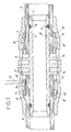
La figure 1 représente un raccord 2 pour deux tubes
comprenant un corps 3 sur lequel est engagée une coiffe 4. Le corps
comprend, pour chaque tube à raccorder 5 une partie tubulaire 6 de
section correspondante au diamètre intérieur du tube, dans laquelle est
ménagée une gorge 7 servant au logement d'un joint 8 destiné à assurer
l'étanchéité avec l'intérieur du tube. Une collerette 9 est destinée à servir
de butée à l'extrémité de chaque tube lors de l'introduction de celui-ci sur
la partie tubulaire correspondante. La coiffe 4 délimite avec le corps 3, et
du côté de chaque tube une chambre 10 servant au logement d'une bague
d'accrochage 12. Chaque chambre 10 comprend une partie annulaire, de
section constante se rétrécissant du côté de l'extrémité libre du raccord
par une surface 13 inclinée de l'extérieur vers l'intérieur et depuis le centre
du raccord vers l'extrémité de celui-ci. La coiffe 4 comporte également, à
partir de chaque collerette 9, une série de fenêtres 14 ménagées sur sa
périphérie. Chaque bague d'accrochage 12 comprend un corps cylindrique
à partir duquel s'étendent axialement plusieurs dents 15 séparées les unes
des autres par des fentes 16, chaque dent comportant à son extrémité
libre, d'une part une face extérieure 17 inclinée de l'extérieur vers
l'intérieur et de l'arrière vers l'avant, destinée à coopérer avec une
surface 13 d'une coiffe, et d'autre part, du côté intérieur, une arête 18
destinée à pénétrer dans la surface extérieure de la paroi du tube à
raccorder. Le corps de la bague d'accrochage comporte un épaulement
annulaire 19 continu ou non, à partir duquel s'étendent vers l'arrière des
plots 20 destinés à venir prendre appui contre une collerette 9 du corps.FIG. 1 shows a coupling 2 for two tubes
comprising a
Chaque fenêtre ménagée dans la coiffe s'étend axialement,
sensiblement depuis une collerette 9 du corps 3 jusqu'au-delà de
l'épaulement de la bague d'accrochage, lorsque les plots de celle-ci sont en
appui contre la collerette.Each window formed in the cap extends axially,
substantially from a
D'un point de vue pratique, lorsqu'un tube 5 est engagé dans le
raccord, il pénètre dans celui-ci jusqu'à ce que son extrémité vienne en
appui contre une collerette 9. Lorsque l'on retire légèrement le tube 5 vers
l'extérieur, les arêtes 18 de la bague d'accrochage 12 correspondante
pénètre dans la surface extérieure de la paroi du tube et la bague
d'accrochage 12 accompagne le mouvement du tube, sa surface
inclinée 17 venant en appui contre la surface inclinée de la coiffe 4,
provoquant un rapprochement des dents 15 et par suite d'une pénétration
plus importante des arêtes 18 dans le tube, empêchant tout retrait de
celui-ci. Cette position de verrouillage d'un tube est représentée dans la
partie droite de la figure 3.From a practical point of view, when a
Pour retirer un tube, il convient de repousser celui-ci jusqu'à ce
que l'extrémité du tube revienne en butée contre une collerette 9, comme
représenté à la partie gauche de la figure 3. La bague d'accrochage 12
correspondante revient avec le tube. Il est alors possible d'introduire un
outil 22 à travers une fenêtre 14 pour que l'outil soit engagé derrière
l'épaulement 19, entre celui-ci et le bord de la fenêtre située du côté de
l'extrémité correspondante du raccord. Il est alors possible de retirer le
tube sans que la bague d'accrochage n'accompagne le mouvement du tube
et retienne celui-ci.To remove a tube, it should be pushed back until
that the end of the tube abuts against a
Les figures 4 et 5 représentent un outil adapté pour immobiliser
axialement une bague d'accrochage 12 lors du retrait d'un tube. Cet outil
est constitué par un cavalier 23 en matière synthétique élastiquement
déformable, comportant une palette de manutention 24, à partir de laquelle
s'étendent deux branches arrondies. Les branches portent au moins un
doigt 25 tourné radialement vers l'intérieur et destiné à venir s'engager
entre l'épaulement 19 de la bague d'accrochage et le bord de la fenêtre
situé du côté libre du raccord, comme montré à la figure 5.Figures 4 and 5 show a tool adapted to immobilize
axially a
Les figures 6 et 7 représentent un autre outil destiné à
immobiliser une bague d'accrochage en position verrouillée d'un tube. Cet
outil est constitué par un cavalier 26 réalisé en une matière synthétique
déformable élastiquement. Ce cavalier 26 comprend une palette de
manutention 27 à partir de laquelle s'étendent deux branches arrondies
dont chacune porte au moins un doigt 28 dirigé radialement vers l'intérieur
et destiné à pénétrer dans une fenêtre 14 pour s'engager entre la
collerette 9 du corps formant butée et le bord arrière d'un plot de la bague
d'accrochage, ou l'épaulement de cette même bague. Il n'est ainsi pas
possible de repousser le tube vers l'intérieur du raccord pour permettre son
retrait hors du tube.Figures 6 and 7 represent another tool for
immobilize a snap ring in the locked position of a tube. This
tool is constituted by a
Les figures 8 et 9 représentent un autre outil. Cet outil est
constitué par un cavalier 29 réalisé en matière synthétique déformable
élastiquement. Le cavalier 29 dont la structure est similaire à celle des
cavaliers 23 et 26 comprend une palette de manutention à partir de
laquelle s'étendant deux hanches arrondies dont chacune porte au moins
un doigt 30 dirigé radialement vers l'intérieur.Figures 8 and 9 represent another tool. This tool is
constituted by a
Le cavalier 29 présente une double fonction. En effet, comme le
montre la figure 8, le doigt 30 vient s'engager entre l'épaulement 19 de la
bague d'accrochage et le bord de la fenêtre situé du côté libre du raccord.
La bague d'accrochage 12 est ainsi immobilisée lors du retrait d'un tube.
Comme le montre la figure 9, le même cavalier 29 peut être retourné de
telle sorte que le doigt 30 pénètre dans la fenêtre 14 pour s'engager entre
la collerette 9 et le bord arrière d'un plot de la bague d'accrochage, ou
l'épaulement de cette même bague. La bague d'accrochage est ainsi
immobilisée en position verrouillée d'un tube.
Comme il ressort de ce qui précède l'invention apporte une grande amélioration à la technique existante en fournissant un raccord instantané démontable de structure très simple, réalisé de façon économique à partir d'un faible nombre de pièces, et d'une utilisation très pratique pour l'opérateur, permettant de maintenir la ou les bagues d'accrochage en position non verrouillée pour procéder à des montages blancs, ou pour démonter le raccord, et de verrouiller et de maintenir les tubes en position verrouillée, lorsque besoin est.As is apparent from the above, the invention provides a great improvement to the existing technique by providing a fitting removable snapshot of very simple structure, realized in a economic from a small number of parts, and a very use convenient for the operator, to maintain the ring (s) latching in the unlocked position to mount blanks, or to disassemble the fitting, and to lock and hold the tubes in locked position, when needed.
Claims (7)
Applications Claiming Priority (2)
| Application Number | Priority Date | Filing Date | Title |
|---|---|---|---|
| FR0114155 | 2001-10-31 | ||
| FR0114155A FR2831643B1 (en) | 2001-10-31 | 2001-10-31 | REMOVABLE INSTANTANEOUS CONNECTION FOR AT LEAST ONE TUBE |
Publications (3)
| Publication Number | Publication Date |
|---|---|
| EP1308662A2 true EP1308662A2 (en) | 2003-05-07 |
| EP1308662A3 EP1308662A3 (en) | 2003-10-15 |
| EP1308662B1 EP1308662B1 (en) | 2004-11-17 |
Family
ID=8868977
Family Applications (1)
| Application Number | Title | Priority Date | Filing Date |
|---|---|---|---|
| EP02356217A Expired - Lifetime EP1308662B1 (en) | 2001-10-31 | 2002-10-30 | Quick-acting disconnectable coupling for at least one tube |
Country Status (6)
| Country | Link |
|---|---|
| EP (1) | EP1308662B1 (en) |
| AT (1) | ATE282788T1 (en) |
| DE (1) | DE60201959T2 (en) |
| ES (1) | ES2231661T3 (en) |
| FR (1) | FR2831643B1 (en) |
| PT (1) | PT1308662E (en) |
Cited By (11)
| Publication number | Priority date | Publication date | Assignee | Title |
|---|---|---|---|---|
| FR2855589A1 (en) * | 2003-05-28 | 2004-12-03 | Legris Sa | INSTANT CONNECTION DEVICE |
| WO2006126774A1 (en) * | 2005-04-23 | 2006-11-30 | Andong Zion Foudation Of Social Welfare Facilities | Holder for pipe fittings |
| WO2007004861A1 (en) * | 2005-07-03 | 2007-01-11 | Widee B.V. | Coupling between two bodies comprising an elastically deformable cutting ring with a screw thread forming cutting lips |
| NL1029414C2 (en) * | 2005-07-03 | 2007-01-19 | Widee Bv | Coupling is between two bodies, which comprises elastically deformable cutting ring with a screw thread forming cutting lips |
| GB2431209A (en) * | 2005-10-14 | 2007-04-18 | Hepworth Building Prod | Pipe insert for multi-layered pipe |
| EP2112416A1 (en) | 2008-04-25 | 2009-10-28 | Comap | Instant connection for at least one tube |
| US8056937B2 (en) | 2006-12-12 | 2011-11-15 | John Guest International Limited | Tube couplings |
| FR2969737A1 (en) * | 2012-04-16 | 2012-06-29 | Parker Hannifin Mfg France | Device for replacing tube with another tube sealingly engaged in channel body of portion of fluid transport circuit to distribute beer, has union provided with male ends respectively arranged to be engaged in tube and another tube |
| CN101761719B (en) * | 2009-08-11 | 2013-06-19 | 叶炎彬 | Rapid pipeline connector |
| US9157643B2 (en) | 2010-10-14 | 2015-10-13 | Fimcim S.P.A. | Conditioning plant |
| US9611958B1 (en) | 2007-01-05 | 2017-04-04 | Zurn Industries, Llc | Combination mechanical/fusion pipe fitting with push connect coupling arrangement |
Families Citing this family (6)
| Publication number | Priority date | Publication date | Assignee | Title |
|---|---|---|---|---|
| NZ531121A (en) * | 2004-02-12 | 2004-10-29 | Mm Kembla New Zealand Ltd | Push-in pipe connector with pretension spring between collar-and-fingers component and connector |
| DE202007011229U1 (en) | 2007-08-11 | 2008-12-24 | Uponor Innovation Ab | Plug-in fitting for a pipe, in particular plastic pipe or plastic-metal composite pipe |
| EP2256394A1 (en) * | 2009-05-29 | 2010-12-01 | Wavin B.V. | Release tool for a push-fit pipe fitting |
| IL259057B (en) * | 2018-04-30 | 2019-11-28 | Efraim Natan | Releasable connector |
| FR3114370A1 (en) * | 2020-09-22 | 2022-03-25 | Comap | Push-in fitting for tubing |
| AU2022202293B1 (en) * | 2022-04-06 | 2023-01-05 | Philmac Pty Ltd | A push-fit pipe fitting with a visual indicator |
Citations (3)
| Publication number | Priority date | Publication date | Assignee | Title |
|---|---|---|---|---|
| US2423632A (en) * | 1943-10-21 | 1947-07-08 | Eastman Mfg Company | Coupling |
| US3097866A (en) * | 1960-11-14 | 1963-07-16 | Weatherhead Co | Pressurized hose end |
| EP0447723A1 (en) * | 1990-03-23 | 1991-09-25 | Nitta Moore Company | Pipe joint |
-
2001
- 2001-10-31 FR FR0114155A patent/FR2831643B1/en not_active Expired - Lifetime
-
2002
- 2002-10-30 AT AT02356217T patent/ATE282788T1/en active
- 2002-10-30 DE DE60201959T patent/DE60201959T2/en not_active Expired - Lifetime
- 2002-10-30 PT PT02356217T patent/PT1308662E/en unknown
- 2002-10-30 EP EP02356217A patent/EP1308662B1/en not_active Expired - Lifetime
- 2002-10-30 ES ES02356217T patent/ES2231661T3/en not_active Expired - Lifetime
Patent Citations (3)
| Publication number | Priority date | Publication date | Assignee | Title |
|---|---|---|---|---|
| US2423632A (en) * | 1943-10-21 | 1947-07-08 | Eastman Mfg Company | Coupling |
| US3097866A (en) * | 1960-11-14 | 1963-07-16 | Weatherhead Co | Pressurized hose end |
| EP0447723A1 (en) * | 1990-03-23 | 1991-09-25 | Nitta Moore Company | Pipe joint |
Cited By (18)
| Publication number | Priority date | Publication date | Assignee | Title |
|---|---|---|---|---|
| WO2004109175A1 (en) * | 2003-05-28 | 2004-12-16 | Legris Sa | Instantaneous connection device |
| KR100712030B1 (en) * | 2003-05-28 | 2007-04-27 | 레그리스소시에떼아노님 | Instantaneous connection device |
| US7448655B2 (en) | 2003-05-28 | 2008-11-11 | Legris Sa | Instantaneous connection device |
| FR2855589A1 (en) * | 2003-05-28 | 2004-12-03 | Legris Sa | INSTANT CONNECTION DEVICE |
| CN1795346B (en) * | 2003-05-28 | 2010-12-01 | 勒格里股份有限公司 | Instantaneous connection device |
| WO2006126774A1 (en) * | 2005-04-23 | 2006-11-30 | Andong Zion Foudation Of Social Welfare Facilities | Holder for pipe fittings |
| WO2007004861A1 (en) * | 2005-07-03 | 2007-01-11 | Widee B.V. | Coupling between two bodies comprising an elastically deformable cutting ring with a screw thread forming cutting lips |
| NL1029414C2 (en) * | 2005-07-03 | 2007-01-19 | Widee Bv | Coupling is between two bodies, which comprises elastically deformable cutting ring with a screw thread forming cutting lips |
| GB2431209A (en) * | 2005-10-14 | 2007-04-18 | Hepworth Building Prod | Pipe insert for multi-layered pipe |
| US8056937B2 (en) | 2006-12-12 | 2011-11-15 | John Guest International Limited | Tube couplings |
| US9611958B1 (en) | 2007-01-05 | 2017-04-04 | Zurn Industries, Llc | Combination mechanical/fusion pipe fitting with push connect coupling arrangement |
| EP2112416A1 (en) | 2008-04-25 | 2009-10-28 | Comap | Instant connection for at least one tube |
| RU2477414C2 (en) * | 2008-04-25 | 2013-03-10 | Комап | Fast-release coupling for one or several pipes |
| CN101761719B (en) * | 2009-08-11 | 2013-06-19 | 叶炎彬 | Rapid pipeline connector |
| US9157643B2 (en) | 2010-10-14 | 2015-10-13 | Fimcim S.P.A. | Conditioning plant |
| US9506662B2 (en) | 2010-10-14 | 2016-11-29 | Fimcim S.P.A. | Conditioning plant |
| EP2653441A1 (en) | 2012-04-16 | 2013-10-23 | Parker Hannifin Manufacturing France SAS | Device and method for replacing a tube defining a portion of a fluid-transport circuit |
| FR2969737A1 (en) * | 2012-04-16 | 2012-06-29 | Parker Hannifin Mfg France | Device for replacing tube with another tube sealingly engaged in channel body of portion of fluid transport circuit to distribute beer, has union provided with male ends respectively arranged to be engaged in tube and another tube |
Also Published As
| Publication number | Publication date |
|---|---|
| ES2231661T3 (en) | 2005-05-16 |
| PT1308662E (en) | 2005-02-28 |
| EP1308662A3 (en) | 2003-10-15 |
| FR2831643A1 (en) | 2003-05-02 |
| EP1308662B1 (en) | 2004-11-17 |
| ATE282788T1 (en) | 2004-12-15 |
| FR2831643B1 (en) | 2004-06-04 |
| DE60201959D1 (en) | 2004-12-23 |
| DE60201959T2 (en) | 2005-11-03 |
Similar Documents
| Publication | Publication Date | Title |
|---|---|---|
| EP1308662B1 (en) | Quick-acting disconnectable coupling for at least one tube | |
| EP0723103B1 (en) | Device for rapidly connecting a tube to a rigid element | |
| EP0510240B2 (en) | Connecting device | |
| EP1064489B1 (en) | Snap-on pipe fitting | |
| EP2439440B1 (en) | Coupling device with locking by threaded clamps and coupling including such a device | |
| EP0715111B1 (en) | Quick connecting device for coupling a tube to a rigid joining part | |
| EP0488844B1 (en) | Connection device, especially for assembling a hose to a car heat exchanger | |
| EP1328750B1 (en) | Connecting device comprising means for instantaneous connection of a pipe end to a member and means for protecting the connection | |
| EP1627173B1 (en) | Instantaneous connection device | |
| WO2005066534A1 (en) | Quick coupling device | |
| EP2615348A2 (en) | Fast coupling | |
| EP1273843A1 (en) | Reusable coupling for connecting the ends of a reinforced hose | |
| EP1258666B9 (en) | Quick connector with fastening by elastic external ring | |
| FR2891889A1 (en) | End piece for sealed connect coupling, has rear edge presenting female configuration comprising annular groove and annular protection wall extending towards rear from outer edge of annular groove | |
| FR2683017A1 (en) | Coupling for tubes | |
| EP1291568B1 (en) | Quick-acting coupling for deformable pipes | |
| EP0989348B1 (en) | Quick-acting pipe coupling | |
| EP0740101A1 (en) | Quick acting coupling having an autonomously loaded valve | |
| FR2675999A1 (en) | Safety syringe | |
| EP4124788A1 (en) | Male element for fluid connector and fluid connector comprising such a male element | |
| EP0811797B1 (en) | Quick acting safety coupling for the disconnectable connection of pipe lines | |
| FR2746893A1 (en) | CONNECTION FOR THE CONNECTION OF TUBES FOR THE TRANSPORT OF FLUIDS | |
| FR2796122A1 (en) | INSTANTANEOUS CONNECTION FOR COMPOSITE TUBE WITH METAL CORE | |
| FR2641600A1 (en) | END CONNECTION FOR PIPES | |
| FR2578621A1 (en) | End connector for semi-stiff plastics pipe |
Legal Events
| Date | Code | Title | Description |
|---|---|---|---|
| PUAI | Public reference made under article 153(3) epc to a published international application that has entered the european phase |
Free format text: ORIGINAL CODE: 0009012 |
|
| AK | Designated contracting states |
Designated state(s): AT BE BG CH CY CZ DE DK EE ES FI FR GB GR IE IT LI LU MC NL PT SE SK TR |
|
| AX | Request for extension of the european patent |
Extension state: AL LT LV MK RO SI |
|
| PUAL | Search report despatched |
Free format text: ORIGINAL CODE: 0009013 |
|
| AK | Designated contracting states |
Kind code of ref document: A3 Designated state(s): AT BE BG CH CY CZ DE DK EE ES FI FR GB GR IE IT LI LU MC NL PT SE SK TR |
|
| AX | Request for extension of the european patent |
Extension state: AL LT LV MK RO SI |
|
| 17P | Request for examination filed |
Effective date: 20040301 |
|
| GRAP | Despatch of communication of intention to grant a patent |
Free format text: ORIGINAL CODE: EPIDOSNIGR1 |
|
| AKX | Designation fees paid |
Designated state(s): AT BE BG CH CY CZ DE DK EE ES FI FR GB GR IE IT LI LU MC NL PT SE SK TR |
|
| GRAS | Grant fee paid |
Free format text: ORIGINAL CODE: EPIDOSNIGR3 |
|
| GRAA | (expected) grant |
Free format text: ORIGINAL CODE: 0009210 |
|
| AK | Designated contracting states |
Kind code of ref document: B1 Designated state(s): AT BE BG CH CY CZ DE DK EE ES FI FR GB GR IE IT LI LU MC NL PT SE SK TR |
|
| PG25 | Lapsed in a contracting state [announced via postgrant information from national office to epo] |
Ref country code: SK Free format text: LAPSE BECAUSE OF FAILURE TO SUBMIT A TRANSLATION OF THE DESCRIPTION OR TO PAY THE FEE WITHIN THE PRESCRIBED TIME-LIMIT Effective date: 20041117 Ref country code: TR Free format text: LAPSE BECAUSE OF FAILURE TO SUBMIT A TRANSLATION OF THE DESCRIPTION OR TO PAY THE FEE WITHIN THE PRESCRIBED TIME-LIMIT Effective date: 20041117 Ref country code: FI Free format text: LAPSE BECAUSE OF FAILURE TO SUBMIT A TRANSLATION OF THE DESCRIPTION OR TO PAY THE FEE WITHIN THE PRESCRIBED TIME-LIMIT Effective date: 20041117 Ref country code: IE Free format text: LAPSE BECAUSE OF FAILURE TO SUBMIT A TRANSLATION OF THE DESCRIPTION OR TO PAY THE FEE WITHIN THE PRESCRIBED TIME-LIMIT Effective date: 20041117 Ref country code: EE Free format text: LAPSE BECAUSE OF FAILURE TO SUBMIT A TRANSLATION OF THE DESCRIPTION OR TO PAY THE FEE WITHIN THE PRESCRIBED TIME-LIMIT Effective date: 20041117 Ref country code: BG Free format text: LAPSE BECAUSE OF FAILURE TO SUBMIT A TRANSLATION OF THE DESCRIPTION OR TO PAY THE FEE WITHIN THE PRESCRIBED TIME-LIMIT Effective date: 20041117 |
|
| REG | Reference to a national code |
Ref country code: GB Ref legal event code: FG4D Free format text: NOT ENGLISH |
|
| REG | Reference to a national code |
Ref country code: CH Ref legal event code: EP |
|
| GBT | Gb: translation of ep patent filed (gb section 77(6)(a)/1977) |
Effective date: 20041117 |
|
| REG | Reference to a national code |
Ref country code: IE Ref legal event code: FG4D Free format text: FRENCH |
|
| REF | Corresponds to: |
Ref document number: 60201959 Country of ref document: DE Date of ref document: 20041223 Kind code of ref document: P |
|
| PG25 | Lapsed in a contracting state [announced via postgrant information from national office to epo] |
Ref country code: SE Free format text: LAPSE BECAUSE OF FAILURE TO SUBMIT A TRANSLATION OF THE DESCRIPTION OR TO PAY THE FEE WITHIN THE PRESCRIBED TIME-LIMIT Effective date: 20050217 Ref country code: DK Free format text: LAPSE BECAUSE OF FAILURE TO SUBMIT A TRANSLATION OF THE DESCRIPTION OR TO PAY THE FEE WITHIN THE PRESCRIBED TIME-LIMIT Effective date: 20050217 |
|
| REG | Reference to a national code |
Ref country code: GR Ref legal event code: EP Ref document number: 20050400080 Country of ref document: GR |
|
| REG | Reference to a national code |
Ref country code: PT Ref legal event code: SC4A Free format text: AVAILABILITY OF NATIONAL TRANSLATION Effective date: 20041222 |
|
| REG | Reference to a national code |
Ref country code: ES Ref legal event code: FG2A Ref document number: 2231661 Country of ref document: ES Kind code of ref document: T3 |
|
| REG | Reference to a national code |
Ref country code: IE Ref legal event code: FD4D |
|
| PLBE | No opposition filed within time limit |
Free format text: ORIGINAL CODE: 0009261 |
|
| STAA | Information on the status of an ep patent application or granted ep patent |
Free format text: STATUS: NO OPPOSITION FILED WITHIN TIME LIMIT |
|
| PG25 | Lapsed in a contracting state [announced via postgrant information from national office to epo] |
Ref country code: CY Free format text: LAPSE BECAUSE OF FAILURE TO SUBMIT A TRANSLATION OF THE DESCRIPTION OR TO PAY THE FEE WITHIN THE PRESCRIBED TIME-LIMIT Effective date: 20051030 |
|
| PG25 | Lapsed in a contracting state [announced via postgrant information from national office to epo] |
Ref country code: MC Free format text: LAPSE BECAUSE OF NON-PAYMENT OF DUE FEES Effective date: 20051031 Ref country code: LU Free format text: LAPSE BECAUSE OF NON-PAYMENT OF DUE FEES Effective date: 20051031 |
|
| 26N | No opposition filed |
Effective date: 20050818 |
|
| PG25 | Lapsed in a contracting state [announced via postgrant information from national office to epo] |
Ref country code: FR Free format text: LAPSE BECAUSE OF NON-PAYMENT OF DUE FEES Effective date: 20060630 |
|
| REG | Reference to a national code |
Ref country code: FR Ref legal event code: ST Effective date: 20060630 |
|
| PG25 | Lapsed in a contracting state [announced via postgrant information from national office to epo] |
Ref country code: LI Free format text: LAPSE BECAUSE OF NON-PAYMENT OF DUE FEES Effective date: 20061031 Ref country code: CH Free format text: LAPSE BECAUSE OF NON-PAYMENT OF DUE FEES Effective date: 20061031 |
|
| REG | Reference to a national code |
Ref country code: CH Ref legal event code: PL |
|
| PGFP | Annual fee paid to national office [announced via postgrant information from national office to epo] |
Ref country code: PT Payment date: 20120430 Year of fee payment: 11 Ref country code: DE Payment date: 20120913 Year of fee payment: 11 |
|
| PGFP | Annual fee paid to national office [announced via postgrant information from national office to epo] |
Ref country code: AT Payment date: 20120919 Year of fee payment: 11 |
|
| REG | Reference to a national code |
Ref country code: PT Ref legal event code: MM4A Free format text: LAPSE DUE TO NON-PAYMENT OF FEES Effective date: 20140430 |
|
| REG | Reference to a national code |
Ref country code: AT Ref legal event code: MM01 Ref document number: 282788 Country of ref document: AT Kind code of ref document: T Effective date: 20131030 |
|
| REG | Reference to a national code |
Ref country code: DE Ref legal event code: R119 Ref document number: 60201959 Country of ref document: DE Effective date: 20140501 |
|
| PG25 | Lapsed in a contracting state [announced via postgrant information from national office to epo] |
Ref country code: PT Free format text: LAPSE BECAUSE OF NON-PAYMENT OF DUE FEES Effective date: 20140430 Ref country code: AT Free format text: LAPSE BECAUSE OF NON-PAYMENT OF DUE FEES Effective date: 20131030 Ref country code: DE Free format text: LAPSE BECAUSE OF NON-PAYMENT OF DUE FEES Effective date: 20140501 |
|
| PGFP | Annual fee paid to national office [announced via postgrant information from national office to epo] |
Ref country code: CZ Payment date: 20140922 Year of fee payment: 13 |
|
| PGFP | Annual fee paid to national office [announced via postgrant information from national office to epo] |
Ref country code: ES Payment date: 20141021 Year of fee payment: 13 |
|
| PG25 | Lapsed in a contracting state [announced via postgrant information from national office to epo] |
Ref country code: CZ Free format text: LAPSE BECAUSE OF NON-PAYMENT OF DUE FEES Effective date: 20151030 |
|
| REG | Reference to a national code |
Ref country code: ES Ref legal event code: FD2A Effective date: 20161125 |
|
| PG25 | Lapsed in a contracting state [announced via postgrant information from national office to epo] |
Ref country code: ES Free format text: LAPSE BECAUSE OF NON-PAYMENT OF DUE FEES Effective date: 20151031 |
|
| PGFP | Annual fee paid to national office [announced via postgrant information from national office to epo] |
Ref country code: NL Payment date: 20211101 Year of fee payment: 20 Ref country code: GB Payment date: 20211102 Year of fee payment: 20 |
|
| PGFP | Annual fee paid to national office [announced via postgrant information from national office to epo] |
Ref country code: IT Payment date: 20211102 Year of fee payment: 20 Ref country code: GR Payment date: 20211101 Year of fee payment: 20 Ref country code: BE Payment date: 20211029 Year of fee payment: 20 |
|
| REG | Reference to a national code |
Ref country code: NL Ref legal event code: MK Effective date: 20221029 |
|
| REG | Reference to a national code |
Ref country code: BE Ref legal event code: MK Effective date: 20221030 |
|
| REG | Reference to a national code |
Ref country code: GB Ref legal event code: PE20 Expiry date: 20221029 |
|
| PG25 | Lapsed in a contracting state [announced via postgrant information from national office to epo] |
Ref country code: GB Free format text: LAPSE BECAUSE OF EXPIRATION OF PROTECTION Effective date: 20221029 |