EP1308563A2 - Registration device for an installation device in the sanitary field and method for registration - Google Patents
Registration device for an installation device in the sanitary field and method for registration Download PDFInfo
- Publication number
- EP1308563A2 EP1308563A2 EP02405923A EP02405923A EP1308563A2 EP 1308563 A2 EP1308563 A2 EP 1308563A2 EP 02405923 A EP02405923 A EP 02405923A EP 02405923 A EP02405923 A EP 02405923A EP 1308563 A2 EP1308563 A2 EP 1308563A2
- Authority
- EP
- European Patent Office
- Prior art keywords
- coding
- registration
- parts
- pipe
- pipe sections
- Prior art date
- Legal status (The legal status is an assumption and is not a legal conclusion. Google has not performed a legal analysis and makes no representation as to the accuracy of the status listed.)
- Granted
Links
Images
Classifications
-
- E—FIXED CONSTRUCTIONS
- E03—WATER SUPPLY; SEWERAGE
- E03B—INSTALLATIONS OR METHODS FOR OBTAINING, COLLECTING, OR DISTRIBUTING WATER
- E03B7/00—Water main or service pipe systems
- E03B7/09—Component parts or accessories
-
- F—MECHANICAL ENGINEERING; LIGHTING; HEATING; WEAPONS; BLASTING
- F16—ENGINEERING ELEMENTS AND UNITS; GENERAL MEASURES FOR PRODUCING AND MAINTAINING EFFECTIVE FUNCTIONING OF MACHINES OR INSTALLATIONS; THERMAL INSULATION IN GENERAL
- F16L—PIPES; JOINTS OR FITTINGS FOR PIPES; SUPPORTS FOR PIPES, CABLES OR PROTECTIVE TUBING; MEANS FOR THERMAL INSULATION IN GENERAL
- F16L2201/00—Special arrangements for pipe couplings
- F16L2201/60—Identification or marking
Definitions
- the invention relates to a registration device according to the preamble of claim 1.
- the invention also relates to a method to register such a device and for a such device provided piping or profile rods.
- the invention has for its object a registration device to create an easier registration. This registration should also be carried out directly on site can be.
- the installation device has a continuous coding, the information on the contains built-in parts and that a recording device is provided with which the coding can be read.
- a registration facility is particularly suitable for piping systems and assembly racks.
- the pipe pieces or rods are preferred already in production with continuous coding provided which, for example, the type of pipe section or contains the connecting rod and arranged at fixed intervals is.
- the registration device can be a simple reading device his. This is used for a piece of pipe or a connecting rod Read start and end point. With an absolute The difference calculation can then be carried out in a suitable computer Pipe length can be determined.
- Such a registration facility enables a very simple and automatic registration.
- the Coding only on the elongated connecting parts, so thus attached to the pipe sections or connecting rods is.
- the connecting parts in particular fittings, are on the Pipe pieces or connecting rods identified.
- On the registration device then only the type of connecting part, for example plastic fitting, brass fitting, fitting etc. can be entered.
- the connecting parts can additionally with coding for identification and non-contact Detection.
- the coding consists of several information codes such as bar codes with an optical one Reader can be read and for example on the Outside of the coded parts is printed.
- the barcode contain the above information about the coded parts.
- the coding is spiral applied to the coded parts. This enables on the one hand a simple production of such a coding and on the other hand the possibility to read them in any position.
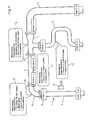
- the fittings 6 and 7 are designed as usual and for example Plastic fittings, brass fittings or press fittings. additionally fittings can also be attached to pipe sections 2 to 5 be connected. Such fittings are, for example, outlet fittings.
- the pipe sections 2 to 5 are, for example, water pipes, but they can also use other pipes, for example gas pipes etc.
- the pipe sections 1 - 5 can be straight, bent or shaped in any other way. They can also be different Have diameter. For example, that Pipe section 4 has a much larger diameter than that Pipe section 2.
- the type of pipe sections 2 - 5 can also vary his.
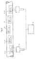
- Coding 8 applied, for example printed or embossed.
- This coding consists of several code A, which are in the same Distances preferably spiral on the outside of the Pipe sections 2 - 5 are applied. These are code A, for example Barcode an "infinite" scale as well as information to the pipe sections 2 - 5 included.
- the code A contain information, with which the pipe sections 2 - 5 are identified. This information can, for example, the size of the diameter and / or contain the pipe type.
- the codes A are, for example, bar codes, that are known per se and that, for example, on the outside the pipe sections 2 - 5 are printed. Such bar code can be used in a continuous production process Procedures can be printed. The pipe sections 2 - 5 are then cut to length from a tube that has the coding 8 already contains.
- the coding 8 is read with a registration device 9 which is, for example, an optical reader.
- the registration device 9 enables a non-contact reading of the coding 8 in which with these the pipe sections 2 - 5 can be read.
- With the registration device 9 is a starting point P1 for each pipe section 2-5 and read an end point P2.
- a computer 10 in the registration device 9 can be integrated with these two measured values the pipe length using an absolute difference calculation of the corresponding pipe section 3 determined.
- the fittings 6 and 7 are preferably not coded Mistake. These fittings 6 and 7 are used for registration Needless to say, must also be recorded as follows certainly.
- the type of this fitting 6 is entered in the registration device 9. For example it is entered that it is a plastic fitting, Brass fitting or a fitting.
- Next Code D and Code A are read on pipe sections 2 and 3. Based on this information, the computer can clearly see the fitting 6 define. With fitting 7, after selecting the type, the Code A, Code B and Code C read. The calculator may be due this information the fitting 7 as such with 3 connections determine.
- the Read pipe sections 2 - 5 and for each fitting 6 and 7 the corresponding one Type can be entered.
- the post calculation can then coupled with a product database easily from the computer 10 can be performed. With the result of this registration exact invoicing is possible.
- a piping system 1 very many fittings and accordingly many pieces of piping.
- the registration device according to the invention can also use a different installation system, in particular be an assembly frame, the connector as well Has connecting rods, in particular profile rods.
- the coding is applied to the connecting rods in this case.
- the connectors correspond to fittings 6 and 7.
- On Such mounting frame is for example under the name GIS known.
Abstract
Description
Die Erfindung betrifft eine Registriereinrichtung nach dem Oberbegriff
des Anspruchs 1. Die Erfindung betrifft zudem ein Verfahren
zum Registrieren einer solchen Vorrichtung sowie für eine
solche Vorrichtung vorgesehene Rohrleitungen oder Profilstangen.The invention relates to a registration device according to the preamble
of
Im sanitären Bereich müssen insbesondere Rohrleitungssysteme zum Erstellen von Nachkalkulationen oder zum Erfassen und Verrechnen von Änderungen gegenüber der Planung registriert werden. Mit einer solchen Registrierung werden die verbauten Teile, also beispielsweise Fittinge und Rohrstücke erfasst und in einer Stückliste zusammengestellt. Bisher wurden zur Registrierung auch bei umfangreichen Rohrleitungssystemen die Rohrstücke von Hand abgemessen und die Fittinge gezählt. Bei Rohrleitungssystemen mit sehr vielen Rohrstücken und Fittingen ist dies jedoch sehr zeitaufwendig.In the sanitary sector, piping systems in particular Creation of post-calculations or for recording and accounting of changes compared to planning. With a such registration will be the built-in parts, for example Fittings and pipe pieces recorded and in a parts list compiled. So far, have also been registered extensive pipe systems, the pipe sections are measured by hand and counted the fittings. With piping systems with very many pipe sections and fittings, however, this is very time-consuming.
Der Erfindung liegt die Aufgabe zugrunde, eine Registriereinrichtung zu schaffen, die eine einfachere Registrierung ermöglicht. Diese Registrierung soll auch direkt vor Ort vorgenommen werden können.The invention has for its object a registration device to create an easier registration. This registration should also be carried out directly on site can be.
Die Aufgabe ist dadurch gelöst, dass die Installationsvorrichtung eine fortlaufende Codierung aufweist, die Angaben zu den verbauten Teilen enthält und dass ein Registriergerät vorgesehen ist, mit welchem die Codierung lesbar ist. Eine solche Registriereinrichtung eignet sich insbesondere für Rohrleitungssysteme und Montagegestelle. Die Rohrstücke bzw. Stangen werden vorzugsweise bereits in der Produktion mit einer fortlaufenden Codierung versehen, welche beispielsweise die Art des Rohrstückes bzw. der Verbindungsstange enthält und in fixen Abständen angeordnet ist. Das Registriergerät kann ein einfaches Lesegerät sein. Mit diesem wird bei einem Rohrstück bzw. einer Verbindungsstange Anfang- und Endpunkt gelesen. Mit einer absoluten Differenzrechnung kann dann in einem geeigneten Rechner die Rohrlänge bestimmt werden. Eine solche Registriereinrichtung ermöglicht ein sehr einfaches und automatisches Registrieren.The object is achieved in that the installation device has a continuous coding, the information on the contains built-in parts and that a recording device is provided with which the coding can be read. Such a registration facility is particularly suitable for piping systems and assembly racks. The pipe pieces or rods are preferred already in production with continuous coding provided which, for example, the type of pipe section or contains the connecting rod and arranged at fixed intervals is. The registration device can be a simple reading device his. This is used for a piece of pipe or a connecting rod Read start and end point. With an absolute The difference calculation can then be carried out in a suitable computer Pipe length can be determined. Such a registration facility enables a very simple and automatic registration.
Nach einer Weiterbildung der Erfindung ist vorgesehen, dass die Codierung lediglich auf den länglichen Verbindungsteilen, also somit auf den Rohrstücken bzw. Verbindungsstangen angebracht ist. Die Verbindungsteile, insbesondere Fittinge werden über die Rohrstücke bzw. Verbindungsstangen identifiziert. Auf dem Registriergerät muss dann lediglich die Art des Verbindungsteils, also beispielsweise Kunstoff-Fitting, Messing-Fitting, Armatur usw. eingegeben werden. Die Verbindungsteile können zusätzlich mit einer Codierung zur Identifikation und zur berührungslosen Erfassung versehen sein. Beim Registrieren müssen dann somit lediglich die länglichen Verbindungsteile, also insbesondere die Rohrstücke und Verbindungsstangen mit dem Registriergerät identifiziert werden. In einem geeigneten Rechner wird dann eine Stückliste erstellt, die gekoppelt mit einer Produktdatenbank die exakte Rechnungsstellung ermöglicht.According to a development of the invention it is provided that the Coding only on the elongated connecting parts, so thus attached to the pipe sections or connecting rods is. The connecting parts, in particular fittings, are on the Pipe pieces or connecting rods identified. On the registration device then only the type of connecting part, for example plastic fitting, brass fitting, fitting etc. can be entered. The connecting parts can additionally with coding for identification and non-contact Detection. When registering, you only have to the elongated connecting parts, in particular the Pipe pieces and connecting rods identified with the registration device become. Then in a suitable computer Bill of materials created, coupled with a product database enables exact invoicing.
Die Codierung besteht nach einer Weiterbildung der Erfindung aus mehreren Informationscode wie Strichcode die mit einem optischen Lesegerät gelesen werden können und die beispielsweise auf der Aussenseite der codierten Teile aufgedruckt ist. Die Strichcode enthalten die oben genannten Angaben über die codierten Teile. According to a further development of the invention, the coding consists of several information codes such as bar codes with an optical one Reader can be read and for example on the Outside of the coded parts is printed. The barcode contain the above information about the coded parts.
Nach einer Weiterbildung der Erfindung ist die Codierung spiralförmig auf den codierten Teilen aufgebracht. Diese ermöglicht einerseits eine einfache Herstellung einer solchen Codierung und anderseits die Möglichkeit, diese in jeder Position zu lesen.According to a development of the invention, the coding is spiral applied to the coded parts. This enables on the one hand a simple production of such a coding and on the other hand the possibility to read them in any position.
Weitere vorteilhafte Merkmale ergeben sich aus den abhängigen Patentansprüchen, der nachfolgenden Beschreibung sowie der Zeichnung.Further advantageous features result from the dependent ones Claims, the following description and the Drawing.
Ein Ausführungsbeispiel der Erfindung wird nachfolgend anhand
der Zeichnung näher erläutert. Es zeigen:
Die Fig. 1 zeigt einen Abschnitt eines Rohrleitungssystems 1,
das Rohrstücke 2 - 5 sowie Fittinge 6 und 7 aufweist. Die Fittinge
6 und 7 sind wie üblich ausgebildet und beispielsweise
Kunststoff-Fittinge, Messing-Fittinge oder Press-Fittinge. Zusätzlich
können hier auch Armaturen an die Rohrstücke 2 bis 5
angeschlossen werden. Solche Armaturen sind beispielsweise Auslaufarmaturen.
Die Rohrstücke 2 bis 5 sind beispielsweise Wasserrohre,
sie können aber auch andere Rohre beispielsweise Gasrohre
usw. sein. Wie ersichtlich können die Rohrstücke 1 - 5 gerade,
gebogen oder sonstwie geformt sein. Sie können auch unterschiedliche
Durchmesser aufweisen. Beispielsweise weist das
Rohrstück 4 einen wesentlich grösseren Durchmesser auf, als das
Rohrstück 2. Auch die Art der Rohrstücke 2 - 5 kann unterschiedlich
sein. 1 shows a section of a
Auf den Rohrstücken 2 - 5 ist gemäss Fig. 2 aussenseitig eine
Codierung 8 aufgebracht, beispielsweise aufgedruckt oder geprägt.
Diese Codierung besteht aus mehreren Code A, die in gleichen
Abständen vorzugsweise spiralförmig auf der Aussenseite der
Rohrstücke 2 - 5 aufgebracht sind. Diese Code A sind beispielsweise
Strichcode die einen "unendlichen" Massstab sowie Angaben
zu den Rohrstücken 2 - 5 enthalten. Die Fig. 2 zeigt auf dem
Rohrstück 3 ganz links den Code A, L1 mit der Länge L=1+0,2. Der
nächste Code A, L2 markiert die Länge L=1+0,4. Der Abstand zwischen
dem Code A, L1 und dem Code A, L2 beträgt in diesem Fall
0,2 m. Die Abstände zwischen benachbarten Code ist immer gleich.
Dieser Abstand kann aber auch kürzer oder länger sein. Ausser
der genannten Längenangabe enthalten die Code A jeweils Angaben,
mit denen die Rohrstücke 2 - 5 identifiziert werden. Diese Angaben
können beispielsweise die Grösse des Durchmessers und/oder
den Rohrtyp enthalten. Die Code A sind beispielsweise Strichcode,
die an sich bekannt sind und die beispielsweise auf die Aussenseite
der Rohrstücke 2 - 5 aufgedruckt sind. Solche Strichcode
können bereits bei der Herstellung des Rohres in einem kontinuierlichen
Verfahren aufgedruckt werden. Die Rohrstücke 2 - 5
werden dann somit von einem Rohr abgelängt, das die Codierung 8
bereits enthält.According to FIG. 2, there is one on the pipe sections 2-5
Die Codierung 8 wird mit einem Registriergerät 9 gelesen, das
beispielsweise ein optisches Lesegerät ist. Das Registriergerät
9 ermöglicht ein berührungsloses Ablesen der Codierung 8, in dem
mit diesen die Rohrstücke 2 - 5 abgelesen werden. Mit dem Registriergerät
9 wird bei jedem Rohrstück 2- 5 ein Anfangpunkt P1
und ein Endpunkt P2 gelesen. In einem Rechner 10, der im Registriergerät
9 integriert sein kann, wird mit diesen beiden Messwerten
mittels einer absoluten Differenzrechnung die Rohrlänge
des entsprechenden Rohrstückes 3 bestimmt. The
Die Fittinge 6 und 7 sind vorzugsweise nicht mit einer Codierung
versehen. Diese Fittinge 6 und 7, welche für die Registrierung
selbstverständlich auch erfasst werden müssen, werden wie folgt
bestimmt. Zur Registrierung beispielsweise des Fittings 6 wird
im Registriergerät 9 der Typ dieses Fittings 6 eingegeben. Beispielsweise
wird eingegeben, dass es sich um einen Kunststoff-Fitting,
Messing-Fitting oder eine Armatur handelt. Als nächstes
werden an den Rohrstücken 2 und 3 die Code D und Code A gelesen.
Aufgrund dieser Angaben kann der Rechner den Fitting 6 eindeutig
definieren. Beim Fitting 7 werden nach dem Wählen des Typs die
Code A, Code B und Code C gelesen. Der Rechner kann aufgrund
dieser Angaben den Fitting 7 als einen solchen mit 3 Anschlüssen
bestimmen.The
Gemäss Figur 1 ergeben sich somit folgende Messvorgäge:
Zur Registrierung müssen beim Rohrleitungssystem 1 somit die
Rohrstücke 2 - 5 abgelesen und zu jedem Fitting 6 und 7 der entsprechende
Typ eingegeben werden. Die Nachkalkulation kann dann
gekoppelt mit einer Produktdatenbank ohne weiteres vom Rechner
10 durchgeführt werden. Mit dem Ergebnis dieser Registrierung
ist eine exakte Rechnungsstellung möglich. In der Praxis enthält
ein solches Rohrleitungssystem 1 sehr viele Fittinge und entsprechend
viele Rohrleitungsstücke. Die erfindungsgemässe Registriereinrichtung
kann aber auch ein anderes Installationssystem,
insbesondere ein Montagegestell sein, das Verbinder sowie
Verbindungsstangen, insbesondere Profilstangen aufweist. Die Codierung
ist in diesem Fall auf den Verbindungsstangen aufgebracht.
Die Verbinder entsprechen den Fittingen 6 und 7. Ein
solches Montagegestell ist beispielsweise unter der Bezeichnung
GIS bekannt.In order to register the
Claims (20)
Applications Claiming Priority (2)
| Application Number | Priority Date | Filing Date | Title |
|---|---|---|---|
| CH20032001 | 2001-11-01 | ||
| CH20032001 | 2001-11-01 |
Publications (3)
| Publication Number | Publication Date |
|---|---|
| EP1308563A2 true EP1308563A2 (en) | 2003-05-07 |
| EP1308563A3 EP1308563A3 (en) | 2004-09-01 |
| EP1308563B1 EP1308563B1 (en) | 2006-04-26 |
Family
ID=4567083
Family Applications (1)
| Application Number | Title | Priority Date | Filing Date |
|---|---|---|---|
| EP02405923A Expired - Lifetime EP1308563B1 (en) | 2001-11-01 | 2002-10-30 | Recording device with installation device and recording apparatus, method for recording an installation device, installation device and conduit or bar for such a recording device |
Country Status (3)
| Country | Link |
|---|---|
| EP (1) | EP1308563B1 (en) |
| AT (1) | ATE324498T1 (en) |
| DE (1) | DE50206541D1 (en) |
Cited By (2)
| Publication number | Priority date | Publication date | Assignee | Title |
|---|---|---|---|---|
| WO2006122579A1 (en) * | 2005-05-18 | 2006-11-23 | Neoperl Gmbh | Sanitary component, namely jet regulator or jet former for flowing, fluid media, method of producing such a sanitary component and use of a sanitary component |
| FR2970270A1 (en) * | 2011-01-10 | 2012-07-13 | Sainte Lizaigne Sa | System for identification and management of water distribution network, has portable computing device allowing entering, editing and deleting information in database, where related information of elements are linked by computing device |
Citations (7)
| Publication number | Priority date | Publication date | Assignee | Title |
|---|---|---|---|---|
| DE2757363A1 (en) * | 1977-12-20 | 1979-06-21 | Siemens Ag | Oblong item measuring system during prodn. - makes mark read at subsequent station controlling further marking operation |
| DE3705994A1 (en) * | 1987-02-20 | 1988-09-01 | Mannesmann Ag | Device and measuring process for the contactless linear measurement of pipes or rods |
| DE3715908A1 (en) * | 1987-05-13 | 1988-12-01 | Messerschmitt Boelkow Blohm | Device for length measurement |
| EP0512412A1 (en) * | 1991-05-07 | 1992-11-11 | Continental Aktiengesellschaft | Method of manufacturing a hose |
| DE4323042A1 (en) * | 1992-12-18 | 1994-06-23 | Toyox Kk | Hose with length markings |
| CH690593A5 (en) * | 1996-03-20 | 2000-10-31 | Geberit Technik Ag | Protective pipe for especially water pipeline with length measurements marked on exterior |
| JP2001346308A (en) * | 2000-06-01 | 2001-12-14 | Hitachi Cable Ltd | Wrapped-type optical fiber cable |
-
2002
- 2002-10-30 EP EP02405923A patent/EP1308563B1/en not_active Expired - Lifetime
- 2002-10-30 AT AT02405923T patent/ATE324498T1/en active
- 2002-10-30 DE DE50206541T patent/DE50206541D1/en not_active Expired - Lifetime
Patent Citations (7)
| Publication number | Priority date | Publication date | Assignee | Title |
|---|---|---|---|---|
| DE2757363A1 (en) * | 1977-12-20 | 1979-06-21 | Siemens Ag | Oblong item measuring system during prodn. - makes mark read at subsequent station controlling further marking operation |
| DE3705994A1 (en) * | 1987-02-20 | 1988-09-01 | Mannesmann Ag | Device and measuring process for the contactless linear measurement of pipes or rods |
| DE3715908A1 (en) * | 1987-05-13 | 1988-12-01 | Messerschmitt Boelkow Blohm | Device for length measurement |
| EP0512412A1 (en) * | 1991-05-07 | 1992-11-11 | Continental Aktiengesellschaft | Method of manufacturing a hose |
| DE4323042A1 (en) * | 1992-12-18 | 1994-06-23 | Toyox Kk | Hose with length markings |
| CH690593A5 (en) * | 1996-03-20 | 2000-10-31 | Geberit Technik Ag | Protective pipe for especially water pipeline with length measurements marked on exterior |
| JP2001346308A (en) * | 2000-06-01 | 2001-12-14 | Hitachi Cable Ltd | Wrapped-type optical fiber cable |
Non-Patent Citations (1)
| Title |
|---|
| PATENT ABSTRACTS OF JAPAN vol. 2002, no. 04, 4. August 2002 (2002-08-04) & JP 2001 346308 A (HITACHI CABLE LTD), 14. Dezember 2001 (2001-12-14) * |
Cited By (6)
| Publication number | Priority date | Publication date | Assignee | Title |
|---|---|---|---|---|
| WO2006122579A1 (en) * | 2005-05-18 | 2006-11-23 | Neoperl Gmbh | Sanitary component, namely jet regulator or jet former for flowing, fluid media, method of producing such a sanitary component and use of a sanitary component |
| AU2005331853B2 (en) * | 2005-05-18 | 2011-09-01 | Neoperl Gmbh | Sanitary component, namely jet regulator or jet former for flowing, fluid media, method of producing such a sanitary component and use of a sanitary component |
| US8925831B2 (en) | 2005-05-18 | 2015-01-06 | Neoperl Gmbh | Sanitary component, namely jet regulator or jet former for flowing, fluid media, method of producing such a sanitary component and use of a sanitary component |
| US9447565B2 (en) | 2005-05-18 | 2016-09-20 | Neoperl Gmbh | Sanitary component, namely jet regulator or jet former for flowing, fluid media, method of producing such a sanitary component and use of a sanitary component |
| US9869075B2 (en) | 2005-05-18 | 2018-01-16 | Neoperl Gmbh | Sanitary component, namely jet regulator or jet former for flowing, fluid media, method of producing such a sanitary component and use of a sanitary component |
| FR2970270A1 (en) * | 2011-01-10 | 2012-07-13 | Sainte Lizaigne Sa | System for identification and management of water distribution network, has portable computing device allowing entering, editing and deleting information in database, where related information of elements are linked by computing device |
Also Published As
| Publication number | Publication date |
|---|---|
| EP1308563B1 (en) | 2006-04-26 |
| DE50206541D1 (en) | 2006-06-01 |
| ATE324498T1 (en) | 2006-05-15 |
| EP1308563A3 (en) | 2004-09-01 |
Similar Documents
| Publication | Publication Date | Title |
|---|---|---|
| DE602005005385T2 (en) | Positioning and recognition of a tool in a tool holder | |
| WO2010112207A1 (en) | Optical cable, having encoded information on length and type of cable | |
| EP2568263A1 (en) | Portable ultrasound flow measurement system, measuring device and measuring tube | |
| DE102016124511A1 (en) | Position detection device | |
| EP3589916B1 (en) | Device and method for determining the length of a line | |
| DE19937120C2 (en) | Steering angle measuring device | |
| EP1095382A1 (en) | Prefabricated electrical installation cable | |
| EP1308563A2 (en) | Registration device for an installation device in the sanitary field and method for registration | |
| EP1220236A2 (en) | Cable | |
| DE10215721B4 (en) | Device for determining the length and the bending angle of a pipe | |
| DE4218985A1 (en) | Identification of individual wires in cable harness - using hand-held scanner to read bar=code pattern of wire insulation for interpretation by computer followed by identification display | |
| DE2064485A1 (en) | Method for making a copy of a tubular or rod-shaped model! | |
| CH690593A5 (en) | Protective pipe for especially water pipeline with length measurements marked on exterior | |
| DE19505513C2 (en) | Single item tracking procedure | |
| DE102009017829B4 (en) | Pipe inspection unit for detecting the curvature of pipes | |
| DE102008031798A1 (en) | Method for transmitting information e.g. electric potential, concerning to sample liquid along liquid channel, involves identifying separation liquids by one of different liquid characteristics by decoding station | |
| EP3534470A1 (en) | Method for wiring two connection points of an electric insulation assembly with a partially pre-terminated electrical cable | |
| LU87594A1 (en) | METHOD AND DEVICE FOR MEASURING THE MASS CURRENT IN A CHANNEL WITH MULTI-PHASE FLOW | |
| DE19902791B4 (en) | Care system for fire hoses | |
| DE2919359A1 (en) | Measured value detector and transmission device - has sections of excitation and sensor coils with different number of turns arranged for mutual section alternations | |
| DD251052A3 (en) | METHOD AND DEVICE FOR DETERMINING RADIENE | |
| DE10005491B4 (en) | Device for inductively measuring the electrical conductivity of a liquid | |
| EP3874927A1 (en) | Method for detecting field boundaries | |
| DE4403222A1 (en) | Cleaning cycle recording appts. for cleaning of pipes, esp. for drink | |
| DE10105927A1 (en) | Method and device for determining the mass of a flowing, foaming fluid stream, in particular a milk stream |
Legal Events
| Date | Code | Title | Description |
|---|---|---|---|
| PUAI | Public reference made under article 153(3) epc to a published international application that has entered the european phase |
Free format text: ORIGINAL CODE: 0009012 |
|
| AK | Designated contracting states |
Designated state(s): AT BE BG CH CY CZ DE DK EE ES FI FR GB GR IE IT LI LU MC NL PT SE SK TR |
|
| AX | Request for extension of the european patent |
Extension state: AL LT LV MK RO SI |
|
| PUAL | Search report despatched |
Free format text: ORIGINAL CODE: 0009013 |
|
| AK | Designated contracting states |
Kind code of ref document: A3 Designated state(s): AT BE BG CH CY CZ DE DK EE ES FI FR GB GR IE IT LI LU MC NL PT SE SK TR |
|
| AX | Request for extension of the european patent |
Extension state: AL LT LV MK RO SI |
|
| RIC1 | Information provided on ipc code assigned before grant |
Ipc: 7E 03B 7/09 A Ipc: 7E 03B 7/00 B |
|
| 17P | Request for examination filed |
Effective date: 20040930 |
|
| 17Q | First examination report despatched |
Effective date: 20050309 |
|
| AKX | Designation fees paid |
Designated state(s): AT BE BG CH CY CZ DE DK EE ES FI FR GB GR IE IT LI LU MC NL PT SE SK TR |
|
| RTI1 | Title (correction) |
Free format text: RECORDING DEVICE WITH INSTALLATION DEVICE AND RECORDING APPARATUS, METHOD FOR RECORDING AN INSTALLATION DEVICE, INSTALLAT |
|
| GRAP | Despatch of communication of intention to grant a patent |
Free format text: ORIGINAL CODE: EPIDOSNIGR1 |
|
| GRAS | Grant fee paid |
Free format text: ORIGINAL CODE: EPIDOSNIGR3 |
|
| GRAA | (expected) grant |
Free format text: ORIGINAL CODE: 0009210 |
|
| AK | Designated contracting states |
Kind code of ref document: B1 Designated state(s): AT BE BG CH CY CZ DE DK EE ES FI FR GB GR IE IT LI LU MC NL PT SE SK TR |
|
| PG25 | Lapsed in a contracting state [announced via postgrant information from national office to epo] |
Ref country code: IT Free format text: LAPSE BECAUSE OF FAILURE TO SUBMIT A TRANSLATION OF THE DESCRIPTION OR TO PAY THE FEE WITHIN THE PRESCRIBED TIME-LIMIT;WARNING: LAPSES OF ITALIAN PATENTS WITH EFFECTIVE DATE BEFORE 2007 MAY HAVE OCCURRED AT ANY TIME BEFORE 2007. THE CORRECT EFFECTIVE DATE MAY BE DIFFERENT FROM THE ONE RECORDED. Effective date: 20060426 Ref country code: IE Free format text: LAPSE BECAUSE OF FAILURE TO SUBMIT A TRANSLATION OF THE DESCRIPTION OR TO PAY THE FEE WITHIN THE PRESCRIBED TIME-LIMIT Effective date: 20060426 Ref country code: NL Free format text: LAPSE BECAUSE OF FAILURE TO SUBMIT A TRANSLATION OF THE DESCRIPTION OR TO PAY THE FEE WITHIN THE PRESCRIBED TIME-LIMIT Effective date: 20060426 Ref country code: FI Free format text: LAPSE BECAUSE OF FAILURE TO SUBMIT A TRANSLATION OF THE DESCRIPTION OR TO PAY THE FEE WITHIN THE PRESCRIBED TIME-LIMIT Effective date: 20060426 Ref country code: SK Free format text: LAPSE BECAUSE OF FAILURE TO SUBMIT A TRANSLATION OF THE DESCRIPTION OR TO PAY THE FEE WITHIN THE PRESCRIBED TIME-LIMIT Effective date: 20060426 Ref country code: CZ Free format text: LAPSE BECAUSE OF FAILURE TO SUBMIT A TRANSLATION OF THE DESCRIPTION OR TO PAY THE FEE WITHIN THE PRESCRIBED TIME-LIMIT Effective date: 20060426 Ref country code: GB Free format text: LAPSE BECAUSE OF FAILURE TO SUBMIT A TRANSLATION OF THE DESCRIPTION OR TO PAY THE FEE WITHIN THE PRESCRIBED TIME-LIMIT Effective date: 20060426 |
|
| REG | Reference to a national code |
Ref country code: GB Ref legal event code: FG4D Free format text: NOT ENGLISH |
|
| REG | Reference to a national code |
Ref country code: CH Ref legal event code: NV Representative=s name: ISLER & PEDRAZZINI AG |
|
| REG | Reference to a national code |
Ref country code: IE Ref legal event code: FG4D Free format text: LANGUAGE OF EP DOCUMENT: GERMAN |
|
| REF | Corresponds to: |
Ref document number: 50206541 Country of ref document: DE Date of ref document: 20060601 Kind code of ref document: P |
|
| PG25 | Lapsed in a contracting state [announced via postgrant information from national office to epo] |
Ref country code: DK Free format text: LAPSE BECAUSE OF FAILURE TO SUBMIT A TRANSLATION OF THE DESCRIPTION OR TO PAY THE FEE WITHIN THE PRESCRIBED TIME-LIMIT Effective date: 20060726 Ref country code: SE Free format text: LAPSE BECAUSE OF FAILURE TO SUBMIT A TRANSLATION OF THE DESCRIPTION OR TO PAY THE FEE WITHIN THE PRESCRIBED TIME-LIMIT Effective date: 20060726 |
|
| PG25 | Lapsed in a contracting state [announced via postgrant information from national office to epo] |
Ref country code: ES Free format text: LAPSE BECAUSE OF FAILURE TO SUBMIT A TRANSLATION OF THE DESCRIPTION OR TO PAY THE FEE WITHIN THE PRESCRIBED TIME-LIMIT Effective date: 20060806 |
|
| PG25 | Lapsed in a contracting state [announced via postgrant information from national office to epo] |
Ref country code: PT Free format text: LAPSE BECAUSE OF FAILURE TO SUBMIT A TRANSLATION OF THE DESCRIPTION OR TO PAY THE FEE WITHIN THE PRESCRIBED TIME-LIMIT Effective date: 20060926 |
|
| PG25 | Lapsed in a contracting state [announced via postgrant information from national office to epo] |
Ref country code: MC Free format text: LAPSE BECAUSE OF NON-PAYMENT OF DUE FEES Effective date: 20061031 |
|
| NLV1 | Nl: lapsed or annulled due to failure to fulfill the requirements of art. 29p and 29m of the patents act | ||
| REG | Reference to a national code |
Ref country code: IE Ref legal event code: FD4D |
|
| GBV | Gb: ep patent (uk) treated as always having been void in accordance with gb section 77(7)/1977 [no translation filed] |
Effective date: 20060426 |
|
| PLBE | No opposition filed within time limit |
Free format text: ORIGINAL CODE: 0009261 |
|
| STAA | Information on the status of an ep patent application or granted ep patent |
Free format text: STATUS: NO OPPOSITION FILED WITHIN TIME LIMIT |
|
| 26N | No opposition filed |
Effective date: 20070129 |
|
| EN | Fr: translation not filed | ||
| REG | Reference to a national code |
Ref country code: CH Ref legal event code: PCAR Free format text: ISLER & PEDRAZZINI AG;POSTFACH 1772;8027 ZUERICH (CH) |
|
| BERE | Be: lapsed |
Owner name: GEBERIT TECHNIK A.G. Effective date: 20061031 |
|
| PG25 | Lapsed in a contracting state [announced via postgrant information from national office to epo] |
Ref country code: GR Free format text: LAPSE BECAUSE OF FAILURE TO SUBMIT A TRANSLATION OF THE DESCRIPTION OR TO PAY THE FEE WITHIN THE PRESCRIBED TIME-LIMIT Effective date: 20060727 Ref country code: FR Free format text: LAPSE BECAUSE OF FAILURE TO SUBMIT A TRANSLATION OF THE DESCRIPTION OR TO PAY THE FEE WITHIN THE PRESCRIBED TIME-LIMIT Effective date: 20070309 |
|
| PG25 | Lapsed in a contracting state [announced via postgrant information from national office to epo] |
Ref country code: EE Free format text: LAPSE BECAUSE OF FAILURE TO SUBMIT A TRANSLATION OF THE DESCRIPTION OR TO PAY THE FEE WITHIN THE PRESCRIBED TIME-LIMIT Effective date: 20060426 Ref country code: BG Free format text: LAPSE BECAUSE OF FAILURE TO SUBMIT A TRANSLATION OF THE DESCRIPTION OR TO PAY THE FEE WITHIN THE PRESCRIBED TIME-LIMIT Effective date: 20060726 |
|
| PG25 | Lapsed in a contracting state [announced via postgrant information from national office to epo] |
Ref country code: TR Free format text: LAPSE BECAUSE OF FAILURE TO SUBMIT A TRANSLATION OF THE DESCRIPTION OR TO PAY THE FEE WITHIN THE PRESCRIBED TIME-LIMIT Effective date: 20060426 Ref country code: LU Free format text: LAPSE BECAUSE OF NON-PAYMENT OF DUE FEES Effective date: 20061030 |
|
| PG25 | Lapsed in a contracting state [announced via postgrant information from national office to epo] |
Ref country code: CY Free format text: LAPSE BECAUSE OF FAILURE TO SUBMIT A TRANSLATION OF THE DESCRIPTION OR TO PAY THE FEE WITHIN THE PRESCRIBED TIME-LIMIT Effective date: 20060426 Ref country code: FR Free format text: LAPSE BECAUSE OF FAILURE TO SUBMIT A TRANSLATION OF THE DESCRIPTION OR TO PAY THE FEE WITHIN THE PRESCRIBED TIME-LIMIT Effective date: 20060426 |
|
| PG25 | Lapsed in a contracting state [announced via postgrant information from national office to epo] |
Ref country code: BE Free format text: LAPSE BECAUSE OF FAILURE TO SUBMIT A TRANSLATION OF THE DESCRIPTION OR TO PAY THE FEE WITHIN THE PRESCRIBED TIME-LIMIT Effective date: 20061031 |
|
| REG | Reference to a national code |
Ref country code: CH Ref legal event code: PUE Owner name: GEBERIT INTERNATIONAL AG Free format text: GEBERIT TECHNIK AG#SCHACHENSTRASSE 77#8645 JONA (CH) -TRANSFER TO- GEBERIT INTERNATIONAL AG#SCHACHENSTRASSE 77#8645 JONA (CH) |
|
| PGFP | Annual fee paid to national office [announced via postgrant information from national office to epo] |
Ref country code: AT Payment date: 20101014 Year of fee payment: 9 |
|
| PGFP | Annual fee paid to national office [announced via postgrant information from national office to epo] |
Ref country code: DE Payment date: 20101022 Year of fee payment: 9 |
|
| PGFP | Annual fee paid to national office [announced via postgrant information from national office to epo] |
Ref country code: IT Payment date: 20101027 Year of fee payment: 9 |
|
| PGFP | Annual fee paid to national office [announced via postgrant information from national office to epo] |
Ref country code: CH Payment date: 20111104 Year of fee payment: 10 |
|
| REG | Reference to a national code |
Ref country code: CH Ref legal event code: PL |
|
| REG | Reference to a national code |
Ref country code: AT Ref legal event code: MM01 Ref document number: 324498 Country of ref document: AT Kind code of ref document: T Effective date: 20121030 |
|
| PG25 | Lapsed in a contracting state [announced via postgrant information from national office to epo] |
Ref country code: CH Free format text: LAPSE BECAUSE OF NON-PAYMENT OF DUE FEES Effective date: 20121031 Ref country code: LI Free format text: LAPSE BECAUSE OF NON-PAYMENT OF DUE FEES Effective date: 20121031 Ref country code: AT Free format text: LAPSE BECAUSE OF NON-PAYMENT OF DUE FEES Effective date: 20121030 Ref country code: DE Free format text: LAPSE BECAUSE OF NON-PAYMENT OF DUE FEES Effective date: 20130501 |
|
| REG | Reference to a national code |
Ref country code: DE Ref legal event code: R119 Ref document number: 50206541 Country of ref document: DE Effective date: 20130501 |
|
| PG25 | Lapsed in a contracting state [announced via postgrant information from national office to epo] |
Ref country code: IT Free format text: LAPSE BECAUSE OF NON-PAYMENT OF DUE FEES Effective date: 20121030 |
|
| REG | Reference to a national code |
Ref country code: DE Ref legal event code: R082 Ref document number: 50206541 Country of ref document: DE Representative=s name: HOEGER, STELLRECHT & PARTNER PATENTANWAELTE, DE |