EP1308360A1 - Hydraulic pressure control valve and vehicle brake device using the same - Google Patents
Hydraulic pressure control valve and vehicle brake device using the same Download PDFInfo
- Publication number
- EP1308360A1 EP1308360A1 EP02024507A EP02024507A EP1308360A1 EP 1308360 A1 EP1308360 A1 EP 1308360A1 EP 02024507 A EP02024507 A EP 02024507A EP 02024507 A EP02024507 A EP 02024507A EP 1308360 A1 EP1308360 A1 EP 1308360A1
- Authority
- EP
- European Patent Office
- Prior art keywords
- valve
- pressure
- hydraulic pressure
- piston
- control
- Prior art date
- Legal status (The legal status is an assumption and is not a legal conclusion. Google has not performed a legal analysis and makes no representation as to the accuracy of the status listed.)
- Granted
Links
- 239000012530 fluid Substances 0.000 claims description 34
- 238000006243 chemical reaction Methods 0.000 claims description 5
- 238000006073 displacement reaction Methods 0.000 claims description 5
- 230000006835 compression Effects 0.000 claims 1
- 238000007906 compression Methods 0.000 claims 1
- 238000010586 diagram Methods 0.000 description 7
- 238000002156 mixing Methods 0.000 description 4
- 230000001172 regenerating effect Effects 0.000 description 4
- 230000000994 depressogenic effect Effects 0.000 description 2
- 230000002159 abnormal effect Effects 0.000 description 1
- 230000005856 abnormality Effects 0.000 description 1
- 230000000881 depressing effect Effects 0.000 description 1
- 238000001514 detection method Methods 0.000 description 1
- 230000000694 effects Effects 0.000 description 1
- 238000000638 solvent extraction Methods 0.000 description 1
Images


Classifications
-
- B—PERFORMING OPERATIONS; TRANSPORTING
- B60—VEHICLES IN GENERAL
- B60T—VEHICLE BRAKE CONTROL SYSTEMS OR PARTS THEREOF; BRAKE CONTROL SYSTEMS OR PARTS THEREOF, IN GENERAL; ARRANGEMENT OF BRAKING ELEMENTS ON VEHICLES IN GENERAL; PORTABLE DEVICES FOR PREVENTING UNWANTED MOVEMENT OF VEHICLES; VEHICLE MODIFICATIONS TO FACILITATE COOLING OF BRAKES
- B60T8/00—Arrangements for adjusting wheel-braking force to meet varying vehicular or ground-surface conditions, e.g. limiting or varying distribution of braking force
- B60T8/32—Arrangements for adjusting wheel-braking force to meet varying vehicular or ground-surface conditions, e.g. limiting or varying distribution of braking force responsive to a speed condition, e.g. acceleration or deceleration
- B60T8/34—Arrangements for adjusting wheel-braking force to meet varying vehicular or ground-surface conditions, e.g. limiting or varying distribution of braking force responsive to a speed condition, e.g. acceleration or deceleration having a fluid pressure regulator responsive to a speed condition
- B60T8/343—Systems characterised by their lay-out
-
- B—PERFORMING OPERATIONS; TRANSPORTING
- B60—VEHICLES IN GENERAL
- B60T—VEHICLE BRAKE CONTROL SYSTEMS OR PARTS THEREOF; BRAKE CONTROL SYSTEMS OR PARTS THEREOF, IN GENERAL; ARRANGEMENT OF BRAKING ELEMENTS ON VEHICLES IN GENERAL; PORTABLE DEVICES FOR PREVENTING UNWANTED MOVEMENT OF VEHICLES; VEHICLE MODIFICATIONS TO FACILITATE COOLING OF BRAKES
- B60T8/00—Arrangements for adjusting wheel-braking force to meet varying vehicular or ground-surface conditions, e.g. limiting or varying distribution of braking force
- B60T8/32—Arrangements for adjusting wheel-braking force to meet varying vehicular or ground-surface conditions, e.g. limiting or varying distribution of braking force responsive to a speed condition, e.g. acceleration or deceleration
- B60T8/321—Arrangements for adjusting wheel-braking force to meet varying vehicular or ground-surface conditions, e.g. limiting or varying distribution of braking force responsive to a speed condition, e.g. acceleration or deceleration deceleration
- B60T8/3255—Systems in which the braking action is dependent on brake pedal data
- B60T8/3275—Systems with a braking assistant function, i.e. automatic full braking initiation in dependence of brake pedal velocity
-
- B—PERFORMING OPERATIONS; TRANSPORTING
- B60—VEHICLES IN GENERAL
- B60T—VEHICLE BRAKE CONTROL SYSTEMS OR PARTS THEREOF; BRAKE CONTROL SYSTEMS OR PARTS THEREOF, IN GENERAL; ARRANGEMENT OF BRAKING ELEMENTS ON VEHICLES IN GENERAL; PORTABLE DEVICES FOR PREVENTING UNWANTED MOVEMENT OF VEHICLES; VEHICLE MODIFICATIONS TO FACILITATE COOLING OF BRAKES
- B60T8/00—Arrangements for adjusting wheel-braking force to meet varying vehicular or ground-surface conditions, e.g. limiting or varying distribution of braking force
- B60T8/32—Arrangements for adjusting wheel-braking force to meet varying vehicular or ground-surface conditions, e.g. limiting or varying distribution of braking force responsive to a speed condition, e.g. acceleration or deceleration
- B60T8/34—Arrangements for adjusting wheel-braking force to meet varying vehicular or ground-surface conditions, e.g. limiting or varying distribution of braking force responsive to a speed condition, e.g. acceleration or deceleration having a fluid pressure regulator responsive to a speed condition
- B60T8/48—Arrangements for adjusting wheel-braking force to meet varying vehicular or ground-surface conditions, e.g. limiting or varying distribution of braking force responsive to a speed condition, e.g. acceleration or deceleration having a fluid pressure regulator responsive to a speed condition connecting the brake actuator to an alternative or additional source of fluid pressure, e.g. traction control systems
- B60T8/4809—Traction control, stability control, using both the wheel brakes and other automatic braking systems
- B60T8/4827—Traction control, stability control, using both the wheel brakes and other automatic braking systems in hydraulic brake systems
Definitions
- This invention relates to a hydraulic pressure control device which permits intervention of electronic control in vehicle braking without changing over a hydraulic circuit, and a vehicle brake device using it.
- This type of brake device has a circuit configuration as shown in Fig. 9 (which shows only a circuit in one line).
- a brake pedal 51 When a brake pedal 51 is depressed, a fluid line 54 extending from a master cylinder 52 to wheel brakes 53 is shut off by a changeover valve 55.
- Brake fluid pressure is supplied from a hydraulic pressure source 56 provided with a power-driven pump through a hydraulic pressure control valve 57 and a changeover valve 58 to the wheel brakes 53.
- the hydraulic pressure control valve 57 uses a spool valve to adjust the brake hydraulic pressure from the hydraulic pressure source 56 to a value proportional to the exciting current and outputs it.
- 59 is a reservoir.
- This type of control valve is known as one which permits delicate hydraulic pressure control compared with hydraulic pressure control valves in which a pressure increasing valve and a pressure reducing valve are combined.
- a brake-by-wire type brake device using such a control valve is disclosed e.g. in JP patent publication 2757862.
- a vehicle brake device of a brake-by-wire type is high in freedom of intervention of electronic control. Besides braking based on the intent of the driver, it can perform various controls such as BA (brake-assist) control, automatic braking such as ASC (active stability control) which, while the driver is not operating the brake pedal, an ECU (electronic control device) 60 performs judging the necessity of speed decrease and vehicle position control, and regenerative blending brake control for electric vehicles and hybrid cars.
- BA brake-assist
- ASC active stability control
- ECU electronic control device 60 performs judging the necessity of speed decrease and vehicle position control
- regenerative blending brake control for electric vehicles and hybrid cars.
- a failure in the line connecting to the hydraulic pressure source 56 is detected based on sensor information from e.g. pressure sensors 61a and 61b.
- the changeover valve 55 is opened to supply the brake fluid pressurized in the master cylinder 52 to the wheel brakes 53.
- Such a conventional device in which detection of a failure is done based on sensor information is inferior in reliability. If the information from sensors is wrong, it is possible that control based on wrong information is carried out, so that even if the line connecting with the hydraulic pressure source 56 fails, the changeover valve 55 is not opened and the brakes do not work.
- sensors for detecting a failure and circuits for carrying out failure judgment are needed. This increases the cost.
- An object of this invention is to provide a simple and highly reliable hydraulic pressure control device and a vehicle brake device using the same.
- a hydraulic pressure control device comprising a housing formed with an input port connected to a hydraulic pressure source, an output port connected to wheel brakes, and a discharge port, a spool valve mounted in the housing so as to be acted by a brake operating force, a first valve portion formed between the spool valve and the discharge port so as to close to disconnect the output port from the discharge port when the spool valve advances, and when the spool valve further makes advancing displacement, a second valve portion formed between the spool valve and the input port so as to open when the spool valve advances further, whereby bringing the input port into communication with the output port, the degrees of opening of the respective valve portions being adjusted according to the amount of displacement of the spool valve, whereby outputting a hydraulic pressure balancing with the brake operating force acted on the spool valve, an offset spring for biasing the spool valve in a backward direction to impart an offset force corresponding to the amount of pressure reduction required for pressure-reducing control, and a pressure chamber for
- a vehicle brake device comprising the hydraulic pressure control device claimed in claim 1, a hydraulic pressure source connected to the input port of the hydraulic pressure control device, a reservoir, a pressure-adjusting valve for receiving a substantially constant pressure P 1 from the hydraulic pressure source and supplying it to the pressure chamber, a first valve for pressure increase control for opening and closing a fluid passage connecting between the pressure-adjusting valve and the pressure chamber, and a valve for pressure reduction control for opening and closing a fluid passage connecting between the pressure chamber and the reservoir, wherein the area a of a pressure-receiving portion of the spool valve which faces the pressure chamber, the force F of the offset spring, and the pressure P 1 adjusted by the pressure-adjusting valve are set so as to satisfy the formula a ⁇ P 1 ⁇ F.
- a vehicle brake device wherein a fluid passage extending from the hydraulic pressure source to the pressure chamber of the hydraulic pressure control device is provided, and a second valve for pressure increase control is provided in the fluid passage for BA control and automatic braking.
- At least one of the first valve for pressure increase control and the valve for pressure reduction control is a valve capable of electric pressure control. Also, a relief valve is preferably provided between the pressure-adjusting valve and the first valve for pressure increase control.
- a vehicle brake device wherein the wheel brakes are divided into two lines, namely, a first line and a second line, with the wheel brakes in the first line in communication with the output port of the hydraulic pressure control device, further comprising a master cylinder and a copying valve, the master cylinder comprising a first piston acted by a brake operating force, a second piston arranged in front of the first piston, a spring arranged between the first piston and the second piston, brake fluid between the first piston and the second piston being pressurized, the master cylinder transmitting the brake operating force to the spool valve of the hydraulic pressure control device through the first piston, the spring and the second piston, the copying valve closing under fluid pressure in the first line while the first line is normal, to shut off a fluid passage extending from the master cylinder to the wheel brakes in the second line, whereby transmitting the hydraulic pressure in the first line to the wheel brakes in the second line, and if the first line fails, the copying valve being kept open so that brake
- the hydraulic pressure control device which has the spool valve, adjusts the hydraulic pressure supplied from the hydraulic pressure source to a value corresponding to the brake operating force (which is larger than the hydraulic pressure that can be generated manually) and outputs it.
- braking is done based on the will of the driver.
- the driver applies an operating force to the spool valve in the same manner as during normal braking. But at this time, the first valve for pressure increase control and the valve for pressure reduction control are driven on command from the ECU to lower the hydraulic pressure introduced into the pressure chamber in the range of P 1 to 0, thereby weaking the braking force.
- the second valve for pressure increase control and the valve for pressure reduction control are driven on command from the ECU to control the hydraulic pressure in the pressure chamber in the range of P 1 to Pmax (maximum hydraulic pressure that the hydraulic pressure source can generate).
- This hydraulic pressure applies force in the advancing direction to the spool valve, so that the brake hydraulic pressure from the hydraulic pressure source is adjusted to a value corresponding to the spool driving force which includes the input from the brake operating member and is supplied to the wheel brakes.
- Fig. 1 shows the first embodiment of this invention.
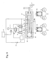
- This brake device comprises a brake operating member (a brake pedal 1 in this embodiment), a hydraulic pressure control device 3 to which an operating force is applied from the brake pedal 1 through an input rod 2, a hydraulic pressure source 4 including a power-driven pump 4a and a pressure accumulator 4b, a pressure adjusting valve 5 connected to the hydraulic pressure source 4, a first valve 6 for pressure increasing control, a valve 7 for pressure reducing control (hereinbelow, they may be simply called valves), wheel brakes 8, and a reservoir 9.
- a brake operating member a brake pedal 1 in this embodiment
- a hydraulic pressure control device 3 to which an operating force is applied from the brake pedal 1 through an input rod 2
- a hydraulic pressure source 4 including a power-driven pump 4a and a pressure accumulator 4b
- a pressure adjusting valve 5 connected to the hydraulic pressure source 4
- a first valve 6 for pressure increasing control
- a valve 7 for pressure reducing control hereinbelow, they may be simply called valves
- the hydraulic pressure control device 3 has a spool valve 32 mounted in a housing 31 which has an input port 31a, output port 31b, discharge port 31c and pressure-adjusting port 31d. It also has a pressure chamber 33 for applying the hydraulic pressure introduced through the pressure-adjusting port 31d to the spool valve 32 with the rear end face of a large-diameter portion formed at the tip of the spool valve 32 as a pressure-receiving surface, and an offset spring 34 biasing the spool valve 32 in the return direction.
- the input port 31a is connected to the hydraulic pressure source 4, the output port 31b to the wheel brakes 8, the discharge port 31c to the reservoir 9, and the pressure-adjusting port 31d to the pressure adjusting valve 5 through the valve 6.
- the pressure-adjusting port 31d is also connected to the reservoir 9 through the valve 7.
- the spool valve 32 has a groove passage 32a.
- the output port 31b communicates with the discharge port 31c through the groove passage 32a.
- a valve portion 35 formed between the shoulder portion of the spool valve 32 and the edge of the discharge port 31c will close, so that the output port 31b is shut off from the discharge port 31c.
- a valve portion 36 formed between the shoulder portion of the spool valve 32 and the edge of the input port 31a will open, so that the output port 31b communicates with the input port 31a.
- valve portions 35 and 36 have their degrees of opening adjusted according to the amount of displacement of the spool valve 32, whereby hydraulic pressure from the hydraulic pressure source 4 is controlled to a value corresponding to the spool driving force and the controlled pressure is supplied to the wheel brakes 8.
- the pressure-adjusting valve 5 receives a constant pressure from the hydraulic pressure source 4 and outputs it.
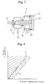
- Fig. 7 shows an example of the pressure-adjusting valve.
- the illustrated pressure-adjusting valve 5 has a pressure-adjusting piston 5a and a valve portion 5b actuated by the piston 5a.
- the piston 5a is a pressure-responsive piston. It has a large-diameter portion and a small-diameter portion.
- the back of the large-diameter portion faces a fluid chamber 5c and its front surface faces an atmospheric chamber 5d (which is open to the atmosphere or connected to the reservoir 9, which is at the atmospheric pressure) and its small-diameter portion is liquid-tightly and slidably inserted in a partitioning wall between the atmospheric chamber 5d and a connecting chamber 5e.
- the pressure-adjusting piston 5a receives hydraulic pressure supplied from the hydraulic pressure source 4 on the back of its large-diameter portion.
- the hydraulic pressure is introduced into the valve 5 through an input port 5f and reach the fluid chamber 5c through a connecting chamber 5e and a connecting passage in the piston.
- the piston 5a moves while compressing a spring 5g to close the valve portion 5b when the piston thrust under the hydraulic pressure exceeds the pressure preset by the spring 5g.
- the hydraulic pressure sealed in the connecting chamber 5e when the valve portion 5b is closed is substantially constant, and the hydraulic pressure flows through the outlet port 5h to the valve 6 in Fig. 1.
- the first valve 6 for pressure increasing control opens and closes a fluid line 10 connecting between the pressure-adjusting valve 5 and the pressure chamber 33.
- the illustrated valve 6 not only merely opens and closes the fluid line, but it can perform pressure control according to the exciting current (such a valve is called a linear valve).
- valve 7 for pressure reducing control also, such a linear valve is used.
- the valve 6 is preferably of a normally open type, while the valve 7 is preferably of a normally closed type.
- hydraulic pressure P 1 (e.g. 2 MPa) adjusted by the pressure-adjusting valve 5 is introduced into the pressure chamber 33 and the driver steps on the brake pedal in normal braking.
- the spool valve 32 controls the hydraulic pressure from the hydraulic pressure source 4 to a value corresponding to the stepping force.
- the controlled hydraulic pressure is supplied to the wheel brakes 8.
- hydraulic pressure in the pressure chamber 33 is controlled in the range of P 1 to 0 by electromagnetic control of the valve 6 and valve 7 based on the command from the ECU (not shown).
- the offset spring force F which has been canceled by the force of A ⁇ P 1 (A is the area of the pressure-receiving portion of the spool valve facing the pressure chamber 33) during normal braking, acts to reduce the spool driving force by the spool driving force.
- the brake force by hydraulic pressure becomes weaker than during normal braking.
- a chamber 37 in which the tip of the spool valve 32 is disposed normally communicates with the output port 31b through a passage 32b formed in the spool valve.
- returning force by the hydraulic pressure introduced into the chamber 37 acts on the spool valve 32.
- a chamber 38 in which the rear end of the spool valve 32 is disposed normally communicates with the reservoir 9 through a passage 31e.
- valve 7 is a linear valve
- an ordinary on-off valve having no pressure control function may be used as the valve 6. If both of the valves 6 and 7 are on-off valves, it is impossible to delicately control the hydraulic pressure in the pressure chamber 33. Thus at least one of them (preferably the valve 7) is preferably a linear valve.
- Fig. 2 shows the second embodiment.
- the vehicle brake device of Fig. 2 is provided with a fluid passage 11 extending from the hydraulic pressure source 4 to the pressure chamber 33 and a second valve 12 for pressure increasing control (a linear valve in the embodiment) is provided in the fluid passage 11. In this regard, it differs from the device of Fig. 1.
- the hydraulic pressure control range by the device of Fig. 2 is shown in Fig. 8.
- the solid line S indicates the hydraulic pressure during normal braking.
- the dotted line indicates the hydraulic pressure during control in which the hydraulic pressure in the pressure chamber 33 is zero.
- pressure-increasing control is performed in the region over the line S.
- pressure-reducing control is performed in the region under the line S (hatched by vertical lines).
- the pressure reduction width a during pressure-reducing control is determined by the force of the offset spring 34. Since the pressure reduction width a is the limit of pressure reduction, pressure will not infinitely drop due to abnormality of electronic control. Thus dangerous situation such as no braking will never occur.
- Fig. 3 shows the third embodiment in which a relief valve 13 is added to the vehicle brake device of Fig. 2.
- the relief valve 13 is provided in a fluid passage between the pressure-adjusting valve 5 and the valve 6. If hydraulic pressure exceeding P 1 is outputted from the pressure-adjusting valve 5 due to its failure, the relief valve 13 serves to release any excess pressure to the reservoir 9 to prevent abnormal pressure rise in the pressure chamber 33. This prevents brake not intended by the driver from being applied.
- Fig. 4 shows the fourth embodiment in which to the device of Fig. 3, a spring 14 for applying operational reaction force to the brake pedal 1 and a spring 15 for transmitting the pedal operating force to the spool valve 32 are added.
- a spring 14 for applying operational reaction force to the brake pedal 1 and a spring 15 for transmitting the pedal operating force to the spool valve 32 are added.
- the input rod 2 is divided into two portions and the spring 15 is disposed between these two portions. But it may be arranged e.g. between the input rod 2 and the spool valve 32.
- Fig. 5 shows the fifth embodiment in which pistons 16 for failsafe are added to the vehicle brake device of Fig. 3.
- the wheel brakes 8 are divided into two lines and a piston 16 for failsafe for transmitting hydraulic pressure is disposed between the wheel brakes in each line and the hydraulic pressure control device 3.
- a piston 16 for failsafe for transmitting hydraulic pressure is disposed between the wheel brakes in each line and the hydraulic pressure control device 3.
- Fig. 6 shows the sixth embodiment in which a master cylinder 17 and a copying valve 18 are added to the vehicle brake device of Fig. 3.
- the wheel brakes are divided into two lines with the wheel brakes 8a in the first line communicating with the output port 31b of the hydraulic pressure control device 3 and the wheel brakes 8b in the second line connected to the hydraulic pressure control device 3 and the master cylinder 17 through the copying valve 18.
- the master cylinder 17 includes a first piston 17a which receives an operating force from the brake pedal 1 through the input rod 2, a second piston 17c arranged in front of the piston 17a through a spring 17b, and an operational reaction force generating spring 17d which also serves as a spring for returning the second piston.
- a spring 15 for transmitting the operating force is disposed between the second piston 17c of the master cylinder and the spool valve 32 with a chamber 17e which the front surface of the second piston 17c faces communicating with the reservoir 9, and a fluid chamber 17f between the first piston 17a and the second piston 17c normally communicating with an output port 17g so that when the first piston 17a returns to the illustrated original position, the fluid chamber 17f communicates with the reservoir 9, too.
- the copying valve 18 includes a piston 18a that is acted on by the hydraulic pressure in the first line and transmits it to the wheel brakes 8b in the second line, a spring 18b for returning the piston 18a, a valve portion 18c adapted to close at the initial period of movement of the piston 18a, thereby cutting the master cylinder 17 off from the wheel brakes 8b in the second line, and a spring 18d that keeps the valve body of the valve portion movable relative to the piston 18a.
- the fluid chamber 17f is pressurized by the first piston 17a before the input port 31a of the hydraulic pressure control device 3 communicates with the output port 31b, so that a large amount of the pressurized brake fluid flows into the wheel brakes 8b.
- a pressure chamber and an offset spring that apply forces in opposite directions to the spool valve are added to a hydraulic pressure control valve which controls, using a spool valve, hydraulic pressure from the hydraulic pressure source to a value corresponding to the brake operating force.
- hydraulic pressure P 1 adjusted by the pressure-adjusting valve is introduced into the pressure chamber.
- hydraulic pressure in the pressure chamber is controlled in the range of P 1 to 0
- the hydraulic pressure in the pressure chamber is controlled in the range of P 1 to Pmax.
- the one using linear valves as the valve for pressure increase control or the valve for pressure reduction control can perform accurate pressure reduction control. This makes it possible to increase the performance of the device.
- the one in which a relief valve is provided between the pressure-adjusting valve and the first valve for pressure increase control, the one in which a piston for failsafe is provided between the wheel brakes and the hydraulic pressure control valve, and the one in which hydraulic pressure is supplied to the wheel brakes in the second line from the master cylinder upon failure of the first line further improve safety and reliability.
- 2nd valve for pressure increase control (linear valve) Valve for pressure reduction control (linear valve) 1st valve for pressure increase control (linear or on-off valve) Pressure reduction in pressure chamber Ordinary brake closed closed open P 1 ⁇ Pressure increase control ⁇ Automatic brake (BA, ASC etc.) linear control linear control closed P 1 ⁇ P max ⁇ Pressure reduction control ⁇ Regenerative blending control closed linear control linear or on-off control 0 ⁇ P 1
Landscapes
- Engineering & Computer Science (AREA)
- Transportation (AREA)
- Mechanical Engineering (AREA)
- Physics & Mathematics (AREA)
- Fluid Mechanics (AREA)
- Regulating Braking Force (AREA)
- Braking Systems And Boosters (AREA)
- Valves And Accessory Devices For Braking Systems (AREA)
Abstract
Description
- This invention relates to a hydraulic pressure control device which permits intervention of electronic control in vehicle braking without changing over a hydraulic circuit, and a vehicle brake device using it.
- Among known vehicle brake devices which permit intervention of electronic control, there is a brake-by-wire type device.
- This type of brake device has a circuit configuration as shown in Fig. 9 (which shows only a circuit in one line). When a
brake pedal 51 is depressed, afluid line 54 extending from amaster cylinder 52 towheel brakes 53 is shut off by achangeover valve 55. Brake fluid pressure is supplied from ahydraulic pressure source 56 provided with a power-driven pump through a hydraulicpressure control valve 57 and achangeover valve 58 to thewheel brakes 53. The hydraulicpressure control valve 57 uses a spool valve to adjust the brake hydraulic pressure from thehydraulic pressure source 56 to a value proportional to the exciting current and outputs it. In the figure, 59 is a reservoir. This type of control valve is known as one which permits delicate hydraulic pressure control compared with hydraulic pressure control valves in which a pressure increasing valve and a pressure reducing valve are combined. A brake-by-wire type brake device using such a control valve is disclosed e.g. in JP patent publication 2757862. - A vehicle brake device of a brake-by-wire type is high in freedom of intervention of electronic control. Besides braking based on the intent of the driver, it can perform various controls such as BA (brake-assist) control, automatic braking such as ASC (active stability control) which, while the driver is not operating the brake pedal, an ECU (electronic control device) 60 performs judging the necessity of speed decrease and vehicle position control, and regenerative blending brake control for electric vehicles and hybrid cars.
- In such a conventional vehicle brake device, upon depressing of the
brake pedal 51, it is detected by a brake switch to close thechangeover valve 55, and brake hydraulic pressure from thehydraulic pressure source 56, which is in a separate line, is controlled to a value corresponding to a command from theECU 60 by means of the hydraulicpressure control valve 57 and supplied to the wheel brakes. - Also, a failure in the line connecting to the
hydraulic pressure source 56 is detected based on sensor information frome.g. pressure sensors changeover valve 55 is opened to supply the brake fluid pressurized in themaster cylinder 52 to thewheel brakes 53. - Such a conventional device in which detection of a failure is done based on sensor information is inferior in reliability. If the information from sensors is wrong, it is possible that control based on wrong information is carried out, so that even if the line connecting with the
hydraulic pressure source 56 fails, thechangeover valve 55 is not opened and the brakes do not work. - Also, sensors for detecting a failure and circuits for carrying out failure judgment are needed. This increases the cost.
- An object of this invention is to provide a simple and highly reliable hydraulic pressure control device and a vehicle brake device using the same.
- According to this invention, there is provided a hydraulic pressure control device comprising a housing formed with an input port connected to a hydraulic pressure source, an output port connected to wheel brakes, and a discharge port, a spool valve mounted in the housing so as to be acted by a brake operating force, a first valve portion formed between the spool valve and the discharge port so as to close to disconnect the output port from the discharge port when the spool valve advances, and when the spool valve further makes advancing displacement, a second valve portion formed between the spool valve and the input port so as to open when the spool valve advances further, whereby bringing the input port into communication with the output port, the degrees of opening of the respective valve portions being adjusted according to the amount of displacement of the spool valve, whereby outputting a hydraulic pressure balancing with the brake operating force acted on the spool valve, an offset spring for biasing the spool valve in a backward direction to impart an offset force corresponding to the amount of pressure reduction required for pressure-reducing control, and a pressure chamber for applying hydraulic pressure introduced from outside to the spool valve in an advancing direction.
- Also, there is provided a vehicle brake device comprising the hydraulic pressure control device claimed in claim 1, a hydraulic pressure source connected to the input port of the hydraulic pressure control device, a reservoir, a pressure-adjusting valve for receiving a substantially constant pressure P1 from the hydraulic pressure source and supplying it to the pressure chamber, a first valve for pressure increase control for opening and closing a fluid passage connecting between the pressure-adjusting valve and the pressure chamber, and a valve for pressure reduction control for opening and closing a fluid passage connecting between the pressure chamber and the reservoir, wherein the area a of a pressure-receiving portion of the spool valve which faces the pressure chamber, the force F of the offset spring, and the pressure P1 adjusted by the pressure-adjusting valve are set so as to satisfy the formula a · P1 < F.
- Further, there is also provided a vehicle brake device wherein a fluid passage extending from the hydraulic pressure source to the pressure chamber of the hydraulic pressure control device is provided, and a second valve for pressure increase control is provided in the fluid passage for BA control and automatic braking.
- In these vehicle brake devices, it is preferable that at least one of the first valve for pressure increase control and the valve for pressure reduction control is a valve capable of electric pressure control. Also, a relief valve is preferably provided between the pressure-adjusting valve and the first valve for pressure increase control.
- Further, according to this invention, there is also provided a vehicle brake device wherein the wheel brakes are divided into two lines, namely, a first line and a second line, with the wheel brakes in the first line in communication with the output port of the hydraulic pressure control device, further comprising a master cylinder and a copying valve, the master cylinder comprising a first piston acted by a brake operating force, a second piston arranged in front of the first piston, a spring arranged between the first piston and the second piston, brake fluid between the first piston and the second piston being pressurized, the master cylinder transmitting the brake operating force to the spool valve of the hydraulic pressure control device through the first piston, the spring and the second piston, the copying valve closing under fluid pressure in the first line while the first line is normal, to shut off a fluid passage extending from the master cylinder to the wheel brakes in the second line, whereby transmitting the hydraulic pressure in the first line to the wheel brakes in the second line, and if the first line fails, the copying valve being kept open so that brake fluid pressurized by the master cylinder is supplied to the wheel brakes in the second line.
- In the vehicle brake device according to this invention, during normal braking, since the pressure chamber of the hydraulic pressure control device of this invention is maintained at hydraulic pressure P1 adjusted by the pressure-adjusting valve and the pressure P1 balances with the offset spring force F, when an operating force is applied from a brake operating member such as the brake pedal to the spool valve, the hydraulic pressure control device, which has the spool valve, adjusts the hydraulic pressure supplied from the hydraulic pressure source to a value corresponding to the brake operating force (which is larger than the hydraulic pressure that can be generated manually) and outputs it. Thus, during normal braking, braking is done based on the will of the driver.
- During pressure reduction control such as regenerative blending brake control, the driver applies an operating force to the spool valve in the same manner as during normal braking. But at this time, the first valve for pressure increase control and the valve for pressure reduction control are driven on command from the ECU to lower the hydraulic pressure introduced into the pressure chamber in the range of P1 to 0, thereby weaking the braking force.
- Further, during pressure increase control such as automatic braking, the second valve for pressure increase control and the valve for pressure reduction control are driven on command from the ECU to control the hydraulic pressure in the pressure chamber in the range of P1 to Pmax (maximum hydraulic pressure that the hydraulic pressure source can generate). This hydraulic pressure applies force in the advancing direction to the spool valve, so that the brake hydraulic pressure from the hydraulic pressure source is adjusted to a value corresponding to the spool driving force which includes the input from the brake operating member and is supplied to the wheel brakes.
- As described above, since pressure reduction and increase by electronic control are possible in addition to ordinary braking without changing over hydraulic circuits, it is not necessary to use failure judgement by the ECU for control. Even if the sensor information is wrong, the will of the driver is reliably reflected on braking, so that reliability of the device increases.
- Operations and effects of the arrangements that have been described above as preferable will be described below.
- Other features and objects of the present invention will become apparent from the following description made with reference to the accompanying drawings, in which:
- Fig. 1 is a circuit diagram of a first embodiment of a vehicle brake device using the hydraulic pressure control device according to this invention;
- Fig. 2 is a circuit diagram of a vehicle brake device of a second embodiment;
- Fig. 3 is a circuit diagram of a vehicle brake device of a third embodiment;
- Fig. 4 is a circuit diagram of a vehicle brake device of a fourth embodiment;
- Fig. 5 is a circuit diagram of a vehicle brake device of a fifth embodiment;
- Fig. 6 is a circuit diagram of a vehicle brake device of a sixth embodiment;
- Fig. 7 is a sectional view showing one example of the pressure-adjusting valve;
- Fig. 8 is a graph showing a hydraulic pressure control range of the vehicle brake device according to this invention; and
- Fig. 9 is a circuit diagram of a conventional brake-by-wire type vehicle brake device in simplified form.
-
- Fig. 1 shows the first embodiment of this invention. This brake device comprises a brake operating member (a brake pedal 1 in this embodiment), a hydraulic
pressure control device 3 to which an operating force is applied from the brake pedal 1 through aninput rod 2, ahydraulic pressure source 4 including a power-driven pump 4a and apressure accumulator 4b, apressure adjusting valve 5 connected to thehydraulic pressure source 4, afirst valve 6 for pressure increasing control, avalve 7 for pressure reducing control (hereinbelow, they may be simply called valves),wheel brakes 8, and areservoir 9. - The hydraulic
pressure control device 3 has aspool valve 32 mounted in ahousing 31 which has aninput port 31a,output port 31b,discharge port 31c and pressure-adjustingport 31d. It also has apressure chamber 33 for applying the hydraulic pressure introduced through the pressure-adjustingport 31d to thespool valve 32 with the rear end face of a large-diameter portion formed at the tip of thespool valve 32 as a pressure-receiving surface, and anoffset spring 34 biasing thespool valve 32 in the return direction. - The force F of the
offset spring 34, the pressure value P1 adjusted by the pressure-adjustingvalve 5, and the pressure-receiving area a of thespool valve 32 facing thepressure chamber 33 are set so as to satisfy the formula a · P1 < F. Since the difference α between a · P1 and F (i.e. a · P1 + α = F) is a force acting to reduce the brake operating force, it is preferably as small as possible. - In this hydraulic
pressure control device 3, theinput port 31a is connected to thehydraulic pressure source 4, theoutput port 31b to thewheel brakes 8, thedischarge port 31c to thereservoir 9, and the pressure-adjustingport 31d to thepressure adjusting valve 5 through thevalve 6. The pressure-adjustingport 31d is also connected to thereservoir 9 through thevalve 7. - The
spool valve 32 has agroove passage 32a. When thespool valve 32 is in the initial position (illustrated in Fig. 1), theoutput port 31b communicates with thedischarge port 31c through thegroove passage 32a. Also, when thespool valve 32 advances, avalve portion 35 formed between the shoulder portion of thespool valve 32 and the edge of thedischarge port 31c will close, so that theoutput port 31b is shut off from thedischarge port 31c. As thespool valve 32 further displaces or advances, avalve portion 36 formed between the shoulder portion of thespool valve 32 and the edge of theinput port 31a will open, so that theoutput port 31b communicates with theinput port 31a. - The
valve portions spool valve 32, whereby hydraulic pressure from thehydraulic pressure source 4 is controlled to a value corresponding to the spool driving force and the controlled pressure is supplied to thewheel brakes 8. - The pressure-adjusting
valve 5 receives a constant pressure from thehydraulic pressure source 4 and outputs it. Fig. 7 shows an example of the pressure-adjusting valve. The illustrated pressure-adjustingvalve 5 has a pressure-adjusting piston 5a and a valve portion 5b actuated by the piston 5a. The piston 5a is a pressure-responsive piston. It has a large-diameter portion and a small-diameter portion. The back of the large-diameter portion faces afluid chamber 5c and its front surface faces anatmospheric chamber 5d (which is open to the atmosphere or connected to thereservoir 9, which is at the atmospheric pressure) and its small-diameter portion is liquid-tightly and slidably inserted in a partitioning wall between theatmospheric chamber 5d and a connectingchamber 5e. - The pressure-adjusting piston 5a receives hydraulic pressure supplied from the
hydraulic pressure source 4 on the back of its large-diameter portion. The hydraulic pressure is introduced into thevalve 5 through an input port 5f and reach thefluid chamber 5c through a connectingchamber 5e and a connecting passage in the piston. The piston 5a moves while compressing aspring 5g to close the valve portion 5b when the piston thrust under the hydraulic pressure exceeds the pressure preset by thespring 5g. The hydraulic pressure sealed in the connectingchamber 5e when the valve portion 5b is closed is substantially constant, and the hydraulic pressure flows through theoutlet port 5h to thevalve 6 in Fig. 1. - The
first valve 6 for pressure increasing control opens and closes afluid line 10 connecting between the pressure-adjustingvalve 5 and thepressure chamber 33. The illustratedvalve 6 not only merely opens and closes the fluid line, but it can perform pressure control according to the exciting current (such a valve is called a linear valve). - For the
valve 7 for pressure reducing control also, such a linear valve is used. Thevalve 6 is preferably of a normally open type, while thevalve 7 is preferably of a normally closed type. - In the brake device of Fig. 1 of such a structure as described above, in normal braking, hydraulic pressure P1 (e.g. 2 MPa) adjusted by the pressure-adjusting
valve 5 is introduced into thepressure chamber 33 and the driver steps on the brake pedal in normal braking. When the brake pedal 1 is stepped in, thespool valve 32 controls the hydraulic pressure from thehydraulic pressure source 4 to a value corresponding to the stepping force. The controlled hydraulic pressure is supplied to thewheel brakes 8. - In pressure-reducing control such as regenerative blending brake control, hydraulic pressure in the
pressure chamber 33 is controlled in the range of P1 to 0 by electromagnetic control of thevalve 6 andvalve 7 based on the command from the ECU (not shown). - At this time, the offset spring force F, which has been canceled by the force of A · P1 (A is the area of the pressure-receiving portion of the spool valve facing the pressure chamber 33) during normal braking, acts to reduce the spool driving force by the spool driving force. Thus the brake force by hydraulic pressure becomes weaker than during normal braking.
- A
chamber 37 in which the tip of thespool valve 32 is disposed normally communicates with theoutput port 31b through apassage 32b formed in the spool valve. With this arrangement, returning force by the hydraulic pressure introduced into thechamber 37 acts on thespool valve 32. Using this force, it is possible to apply a reaction force corresponding to the stepping force to the brake pedal 1. In the illustratedcontrol device 3, achamber 38 in which the rear end of thespool valve 32 is disposed normally communicates with thereservoir 9 through apassage 31e. - If the
valve 7 is a linear valve, an ordinary on-off valve having no pressure control function may be used as thevalve 6. If both of thevalves pressure chamber 33. Thus at least one of them (preferably the valve 7) is preferably a linear valve. - Fig. 2 shows the second embodiment. The vehicle brake device of Fig. 2 is provided with a
fluid passage 11 extending from thehydraulic pressure source 4 to thepressure chamber 33 and asecond valve 12 for pressure increasing control (a linear valve in the embodiment) is provided in thefluid passage 11. In this regard, it differs from the device of Fig. 1. - In the device of Fig. 2, when the
valves valve 12 is opened, hydraulic pressure from thehydraulic pressure source 4 is introduced into thepressure chamber 33. The hydraulic pressure in thepressure chamber 33 is raised to a desired pressure by adjusting the degree of opening of thevalve 12. Also, if necessary, thevalve 7 is opened and its degree'of opening is adjusted to lower the pressure. This makes it possible to control the hydraulic pressure in thepressure chamber 33 in the range of P1 to Pmax. Thus, with this hydraulic pressure, it is possible to assist in the brake operation performed by the driver (BA control), or apply automatic braking by driving thespool 32 while the brake pedal 1 is not being operated. - The control modes and the valve position in the vehicle brake device of Fig. 2 are listed in Table 1.
- The hydraulic pressure control range by the device of Fig. 2 is shown in Fig. 8. The solid line S indicates the hydraulic pressure during normal braking. The dotted line indicates the hydraulic pressure during control in which the hydraulic pressure in the
pressure chamber 33 is zero. When the hydraulic pressure in thepressure chamber 33 is adjusted in the range of P1 to Pmax, pressure-increasing control is performed in the region over the line S. If the hydraulic pressure in thepressure chamber 33 is is controlled in the range of 0 to P1, pressure-reducing control is performed in the region under the line S (hatched by vertical lines). The pressure reduction width a during pressure-reducing control is determined by the force of the offsetspring 34. Since the pressure reduction width a is the limit of pressure reduction, pressure will not infinitely drop due to abnormality of electronic control. Thus dangerous situation such as no braking will never occur. - Fig. 3 shows the third embodiment in which a
relief valve 13 is added to the vehicle brake device of Fig. 2. Therelief valve 13 is provided in a fluid passage between the pressure-adjustingvalve 5 and thevalve 6. If hydraulic pressure exceeding P1 is outputted from the pressure-adjustingvalve 5 due to its failure, therelief valve 13 serves to release any excess pressure to thereservoir 9 to prevent abnormal pressure rise in thepressure chamber 33. This prevents brake not intended by the driver from being applied. - Fig. 4 shows the fourth embodiment in which to the device of Fig. 3, a
spring 14 for applying operational reaction force to the brake pedal 1 and aspring 15 for transmitting the pedal operating force to thespool valve 32 are added. With this device, so-called board-stepping-like hard feeling of the brake pedal 1 is eliminated. Thus the pedal feeling improves. Theinput rod 2 is divided into two portions and thespring 15 is disposed between these two portions. But it may be arranged e.g. between theinput rod 2 and thespool valve 32. - Fig. 5 shows the fifth embodiment in which
pistons 16 for failsafe are added to the vehicle brake device of Fig. 3. In this device, thewheel brakes 8 are divided into two lines and apiston 16 for failsafe for transmitting hydraulic pressure is disposed between the wheel brakes in each line and the hydraulicpressure control device 3. With this arrangement, if e.g. fluid leakage occurs in a wheel brake in one of the lines, the other line is protected and survives. Thus the safety of the vehicle improves. Of course, onepiston 16 for failsafe may be provided for each wheel brake. - Fig. 6 shows the sixth embodiment in which a
master cylinder 17 and a copyingvalve 18 are added to the vehicle brake device of Fig. 3. In this device, the wheel brakes are divided into two lines with the wheel brakes 8a in the first line communicating with theoutput port 31b of the hydraulicpressure control device 3 and thewheel brakes 8b in the second line connected to the hydraulicpressure control device 3 and themaster cylinder 17 through the copyingvalve 18. - The
master cylinder 17 includes afirst piston 17a which receives an operating force from the brake pedal 1 through theinput rod 2, asecond piston 17c arranged in front of thepiston 17a through aspring 17b, and an operational reactionforce generating spring 17d which also serves as a spring for returning the second piston. Aspring 15 for transmitting the operating force is disposed between thesecond piston 17c of the master cylinder and thespool valve 32 with achamber 17e which the front surface of thesecond piston 17c faces communicating with thereservoir 9, and a fluid chamber 17f between thefirst piston 17a and thesecond piston 17c normally communicating with anoutput port 17g so that when thefirst piston 17a returns to the illustrated original position, the fluid chamber 17f communicates with thereservoir 9, too. - The copying
valve 18 includes apiston 18a that is acted on by the hydraulic pressure in the first line and transmits it to thewheel brakes 8b in the second line, aspring 18b for returning thepiston 18a, avalve portion 18c adapted to close at the initial period of movement of thepiston 18a, thereby cutting themaster cylinder 17 off from thewheel brakes 8b in the second line, and a spring 18d that keeps the valve body of the valve portion movable relative to thepiston 18a. - In the device of Fig. 6 which has the copying
valve 18 and themaster cylinder 17, when the brake pedal 1 is depressed, the operating force is transmitted through thefirst piston 17a,spring 17b,second piston 17c andspring 15, and thespool valve 32 is pushed in. With this movement, theinput port 31a communicates with theoutput port 31b, so that hydraulic pressure corresponding to the operating force will be supplied to the wheel brakes 8a in the first line from thehydraulic pressure source 4. Simultaneously, by the hydraulic pressure that has flown into the first line, thevalve portion 18c of the copyingvalve 18 is closed, so that brake fluid in the copying valve is pressurized by thepiston 18a. Thus, hydraulic pressure is supplied to thewheel brakes 8b in the second line, too. - Also, if hydraulic pressure is not supplied to the first line e.g. due to a failure of the
hydraulic pressure source 4, thevalve portion 18c of the copyingvalve 18 will remain open, so that hydraulic pressure generated in themaster cylinder 17, i.e. brake fluid in the fluid chamber 17f, which has been pressurized by thefirst piston 17a, flows to thewheel brakes 8b in the second line through the copyingvalve 18. Thus, a required braking force is ensured for safety. - For the
master cylinder 17, it is not desirable that the fluid chamber 17f is pressurized by thefirst piston 17a before theinput port 31a of the hydraulicpressure control device 3 communicates with theoutput port 31b, so that a large amount of the pressurized brake fluid flows into thewheel brakes 8b. Thus, it is necessary to set the forces of thesprings spring 17b will not be too weak compared to the force of thespring 17d. - As described above, in the hydraulic pressure control device and the vehicle brake device using it according to this invention, a pressure chamber and an offset spring that apply forces in opposite directions to the spool valve are added to a hydraulic pressure control valve which controls, using a spool valve, hydraulic pressure from the hydraulic pressure source to a value corresponding to the brake operating force.
- In a normal state, hydraulic pressure P1 adjusted by the pressure-adjusting valve is introduced into the pressure chamber. On the other hand, during pressure reduction by electronic control, hydraulic pressure in the pressure chamber is controlled in the range of P1 to 0, while during pressure reduction by electronic control, the hydraulic pressure in the pressure chamber is controlled in the range of P1 to Pmax. This eliminates the need of changeover of hydraulic circuits during intervention of electronic control. Thus, there is no need to introduce failure judgement by the ECU into control, and even if the sensor information is wrong, the intention of the driver is reflected on braking. Besides, no pressure reduction exceeding the limit will occur in pressure reduction control, so that reliability increases.
- Also, since the circuit is simplified, compactness and low cost of the device are achieved.
- The one using linear valves as the valve for pressure increase control or the valve for pressure reduction control can perform accurate pressure reduction control. This makes it possible to increase the performance of the device.
- The one in which a relief valve is provided between the pressure-adjusting valve and the first valve for pressure increase control, the one in which a piston for failsafe is provided between the wheel brakes and the hydraulic pressure control valve, and the one in which hydraulic pressure is supplied to the wheel brakes in the second line from the master cylinder upon failure of the first line further improve safety and reliability.
- Besides, the one in which an operational reaction force is applied to the brake pedal by a spring and the pedal operating force is transmitted to the spool valve through the spring improves the pedal feeling.
2nd valve for pressure increase control (linear valve) Valve for pressure reduction control (linear valve) 1st valve for pressure increase control (linear or on-off valve) Pressure reduction in pressure chamber Ordinary brake closed closed open P1 ·Pressure increase control ·Automatic brake (BA, ASC etc.) linear control linear control closed P1∼Pmax ·Pressure reduction control ·Regenerative blending control closed linear control linear or on-off control 0∼P1
Claims (8)
- A hydraulic pressure control device comprising a housing formed with an input port connected to a hydraulic pressure source, an output port connected to wheel brakes, and a discharge port, a spool valve mounted in said housing so as to be acted by a brake operating force, a first valve portion formed between said spool valve and said discharge port so as to close to disconnect said output port from said discharge port when said spool valve advances, and when the spool valve further makes advancing displacement, a second valve portion formed between said spool valve and said input port so as to open when said spool valve advances further, whereby bringing said input port into communication with said output port, the degrees of opening of said respective valve portions being adjusted according to the amount of displacement of said spool valve, whereby outputting a hydraulic pressure balancing with the brake operating force acted on said spool valve, an offset spring for biasing said spool valve in a backward direction to impart an offset force corresponding to the amount of pressure reduction required for pressure-reducing control, and a pressure chamber for applying hydraulic pressure introduced from outside to said spool valve in an advancing direction.
- A vehicle brake device comprising the hydraulic pressure control device claimed in claim 1,
a hydraulic pressure source connected to said input port of said hydraulic pressure control device,
a reservoir,
a pressure-adjusting valve for receiving a substantially constant pressure P1 from said hydraulic pressure source and supplying it to said pressure chamber,
a first valve for pressure increase control for opening and closing a fluid passage connecting between said pressure-adjusting valve and said pressure chamber, and
a valve for pressure reduction control for opening and closing a fluid passage connecting between said pressure chamber and said reservoir,
wherein the area a of a pressure-receiving portion of said spool valve which faces said pressure chamber, the force F of said offset spring, and the pressure P1 adjusted by said pressure-adjusting valve are set so as to satisfy the formula a · P1 < F. - A vehicle brake device as claimed in claim 2 wherein at least one of said first valve for pressure increase control and said valve for pressure reduction control is a valve which is capable of electric pressure control.
- A vehicle brake device as claimed in claim 2 or 3 wherein a fluid passage extending from said hydraulic pressure source to said pressure chamber of said hydraulic pressure control device is provided, and a second valve for pressure increase control is provided in said fluid passage.
- A vehicle brake device as claimed in any of claims 2-4 wherein a relief valve is provided between said pressure-adjusting valve and said first valve for pressure increase control.
- A vehicle brake device as claimed in any of claims 2-5 further comprising a spring for applying an operational reaction force to the brake pedal, and a compression spring for transmitting the pedal operating force to said spool valve.
- A vehicle brake device as claimed in any of claims 2-6 wherein a piston for failsafe for transmitting hydraulic pressure is provided between the wheel brakes and said hydraulic pressure control device.
- A vehicle brake device as claimed in any of claims 2-6 wherein the wheel brakes are divided into two lines, namely, a first line and a second line, with the wheel brakes in the first line in communication with said output port of said hydraulic pressure control device, further comprising a master cylinder and a copying valve, said master cylinder comprising a first piston acted by a brake operating force, a second piston arranged in front of said first piston, a spring arranged between said first piston and said second piston, brake fluid between said first piston and said second piston being pressurized, said master cylinder transmitting the brake operating force to said spool valve of said hydraulic pressure control device through said first piston, said spring and said second piston, said copying valve closing under fluid pressure in said first line while said first line is normal, to shut off a fluid passage extending from said master cylinder to the wheel brakes in said second line, whereby transmitting the hydraulic pressure in said first line to the wheel brakes in said second line, and if said first line fails, said copying valve being kept open so that brake fluid pressurized by said master cylinder is supplied to the wheel brakes in said second line.
Applications Claiming Priority (2)
| Application Number | Priority Date | Filing Date | Title |
|---|---|---|---|
| JP2001334215A JP3884941B2 (en) | 2001-10-31 | 2001-10-31 | Vehicle braking device |
| JP2001334215 | 2001-10-31 |
Publications (2)
| Publication Number | Publication Date |
|---|---|
| EP1308360A1 true EP1308360A1 (en) | 2003-05-07 |
| EP1308360B1 EP1308360B1 (en) | 2006-10-18 |
Family
ID=19149377
Family Applications (1)
| Application Number | Title | Priority Date | Filing Date |
|---|---|---|---|
| EP02024507A Expired - Lifetime EP1308360B1 (en) | 2001-10-31 | 2002-10-30 | Hydraulic pressure control valve and vehicle brake device using the same |
Country Status (4)
| Country | Link |
|---|---|
| US (1) | US6782796B2 (en) |
| EP (1) | EP1308360B1 (en) |
| JP (1) | JP3884941B2 (en) |
| DE (1) | DE60215437T2 (en) |
Families Citing this family (16)
| Publication number | Priority date | Publication date | Assignee | Title |
|---|---|---|---|---|
| JP3906816B2 (en) * | 2003-03-18 | 2007-04-18 | 株式会社アドヴィックス | Hydraulic brake device for vehicles |
| JP2005349985A (en) * | 2004-06-11 | 2005-12-22 | Honda Motor Co Ltd | Vehicle braking device |
| DE102005049300A1 (en) * | 2005-10-12 | 2007-04-26 | Continental Teves Ag & Co. Ohg | Method for determining the wheel pressure in an electronically controllable motor vehicle brake control system |
| DE102009033499A1 (en) * | 2008-07-18 | 2010-01-21 | Continental Teves Ag & Co. Ohg | Brake system for motor vehicles |
| WO2010062019A1 (en) * | 2008-11-03 | 2010-06-03 | Lee Won-Bae | Brake pressure control apparatus which regulates deceleration rate while braking according to brake pressure and method thereof |
| KR100903509B1 (en) * | 2008-10-20 | 2009-06-17 | 원 배 이 | Brake pressure regulating device and method |
| MX2012008481A (en) * | 2010-01-22 | 2012-08-17 | Carefusion 2200 Inc | Hydraulic device including a spool valve and method of use thereof. |
| JP5831006B2 (en) * | 2011-04-05 | 2015-12-09 | 株式会社アドヴィックス | Hydraulic booster and pump back type hydraulic brake device using the same |
| DE102013203589A1 (en) * | 2012-03-06 | 2013-09-12 | Continental Teves Ag & Co. Ohg | Method for operating a brake system and brake system |
| CN103802809A (en) * | 2012-11-08 | 2014-05-21 | 秦皇岛天业通联重工股份有限公司 | Brake control system of mining dump truck and mining dump truck |
| EP2961881B1 (en) * | 2013-03-01 | 2017-10-04 | Feyecon Development & Implementation B.V. | Process of marking a textile substrate |
| US10065618B2 (en) | 2013-04-12 | 2018-09-04 | Ford Global Technologies, Llc | Vehicle braking system and method |
| US9969374B2 (en) * | 2013-05-31 | 2018-05-15 | Ford Global Technologies, Llc | Control and delivery of hydraulic fluid in vehicle braking system |
| JP6278236B2 (en) * | 2014-01-29 | 2018-02-14 | 株式会社アドヴィックス | Braking device for vehicle |
| DE102014117211A1 (en) * | 2014-11-25 | 2016-05-25 | Dr. Ing. H.C. F. Porsche Aktiengesellschaft | Motor vehicle with a hybrid drive |
| JP6250892B2 (en) * | 2015-01-30 | 2017-12-20 | 株式会社アドヴィックス | Braking device for vehicle |
Citations (5)
| Publication number | Priority date | Publication date | Assignee | Title |
|---|---|---|---|---|
| US4159854A (en) * | 1978-05-08 | 1979-07-03 | Caterpillar Tractor Co. | Brake system with pilot actuation |
| US5897175A (en) * | 1995-07-20 | 1999-04-27 | Aisin Seiki | Brake pressure control system for a vehicle |
| US5934326A (en) * | 1997-02-10 | 1999-08-10 | Akebono Brake Industry Co., Ltd. | Pressure regulating valve |
| EP1225111A1 (en) * | 2001-01-23 | 2002-07-24 | Sumitomo (Sei) Brake Systems, Inc. | Hydraulic pressure control device and vehicle brake device comprising the same |
| US20020096937A1 (en) * | 2001-01-23 | 2002-07-25 | Makoto Nishikimi | Hydraulic pressure control device for vehicle and vehicle brake system using the same |
Family Cites Families (7)
| Publication number | Priority date | Publication date | Assignee | Title |
|---|---|---|---|---|
| GB2162604B (en) | 1984-07-30 | 1988-05-25 | Teves Gmbh Alfred | Braking pressure generator for a hydraulic brake system |
| DE3511975C2 (en) | 1985-04-02 | 1987-01-22 | Daimler-Benz Ag, 7000 Stuttgart | Hydraulic brake booster |
| FR2584356B1 (en) | 1985-07-03 | 1990-07-27 | Bendix France | HYDRAULIC ASSISTANCE DEVICE |
| JPH0775963B2 (en) | 1989-03-25 | 1995-08-16 | 住友電気工業株式会社 | Electronically controlled braking device |
| US5577384A (en) | 1994-07-15 | 1996-11-26 | Jidosha Kiki Co., Ltd. | Back-up pressure intensifier for master cylinder failure |
| JP2757862B2 (en) | 1996-10-30 | 1998-05-25 | トヨタ自動車株式会社 | Brake control method |
| DE50011609D1 (en) | 1999-08-25 | 2005-12-22 | Continental Teves & Co Ohg | Brake system for motor vehicles and method for operating a brake system |
-
2001
- 2001-10-31 JP JP2001334215A patent/JP3884941B2/en not_active Expired - Fee Related
-
2002
- 2002-10-01 US US10/260,288 patent/US6782796B2/en not_active Expired - Fee Related
- 2002-10-30 DE DE60215437T patent/DE60215437T2/en not_active Expired - Lifetime
- 2002-10-30 EP EP02024507A patent/EP1308360B1/en not_active Expired - Lifetime
Patent Citations (5)
| Publication number | Priority date | Publication date | Assignee | Title |
|---|---|---|---|---|
| US4159854A (en) * | 1978-05-08 | 1979-07-03 | Caterpillar Tractor Co. | Brake system with pilot actuation |
| US5897175A (en) * | 1995-07-20 | 1999-04-27 | Aisin Seiki | Brake pressure control system for a vehicle |
| US5934326A (en) * | 1997-02-10 | 1999-08-10 | Akebono Brake Industry Co., Ltd. | Pressure regulating valve |
| EP1225111A1 (en) * | 2001-01-23 | 2002-07-24 | Sumitomo (Sei) Brake Systems, Inc. | Hydraulic pressure control device and vehicle brake device comprising the same |
| US20020096937A1 (en) * | 2001-01-23 | 2002-07-25 | Makoto Nishikimi | Hydraulic pressure control device for vehicle and vehicle brake system using the same |
Also Published As
| Publication number | Publication date |
|---|---|
| US6782796B2 (en) | 2004-08-31 |
| EP1308360B1 (en) | 2006-10-18 |
| DE60215437D1 (en) | 2006-11-30 |
| US20030085613A1 (en) | 2003-05-08 |
| JP2003137083A (en) | 2003-05-14 |
| JP3884941B2 (en) | 2007-02-21 |
| DE60215437T2 (en) | 2007-02-01 |
Similar Documents
| Publication | Publication Date | Title |
|---|---|---|
| US6782796B2 (en) | Hydraulic pressure control valve and vehicle brake device using the same | |
| US9371062B2 (en) | Brake device | |
| JP2590825B2 (en) | Manual / Electric dual brake system | |
| US6957871B2 (en) | Vehicle brake device | |
| EP2223832B1 (en) | Vehicular brake system | |
| US6945610B1 (en) | Hydraulic braking system wherein electrically controllable assisting drive force is applied to master cylinder piston upon brake pedal operation | |
| US20080257670A1 (en) | Brake System for Motor Vehicles | |
| US6450589B2 (en) | Brake pressure transducer for a hydraulic vehicle brake system | |
| US20060220451A1 (en) | Electrohydraulic brake system for motor vehicles | |
| EP2412590A2 (en) | Pedal feel simulator actuator and cutoff assembly | |
| US6644760B2 (en) | Hydraulic pressure control device and vehicle brake device using the same | |
| CN110831830B (en) | brake control device | |
| US7410223B2 (en) | Vehicle hydraulic brake device | |
| US20020014379A1 (en) | Brake apparatus | |
| US6732519B2 (en) | Pressure holding valve and vehicle braking device using the same | |
| EP4685022A1 (en) | Vehicle brake system | |
| US6652041B2 (en) | Hydraulic pressure control device for vehicle and vehicle brake system using the same | |
| JP2006306221A (en) | Brake device | |
| JP4849054B2 (en) | Braking device for vehicle | |
| JP4568948B2 (en) | Hydraulic brake device for vehicle | |
| US11524669B2 (en) | Brake controller | |
| GB2177469A (en) | Slip-controlled brake system | |
| JPS62149547A (en) | Liquid pressure brake apparatus associated with liquid pressure booster | |
| JP4512933B2 (en) | Hydraulic brake device | |
| JPH11198797A (en) | Solenoid valve and brake control device provided with the solenoid valve |
Legal Events
| Date | Code | Title | Description |
|---|---|---|---|
| PUAI | Public reference made under article 153(3) epc to a published international application that has entered the european phase |
Free format text: ORIGINAL CODE: 0009012 |
|
| AK | Designated contracting states |
Designated state(s): AT BE BG CH CY CZ DE DK EE ES FI FR GB GR IE IT LI LU MC NL PT SE SK TR |
|
| AX | Request for extension of the european patent |
Extension state: AL LT LV MK RO SI |
|
| 17P | Request for examination filed |
Effective date: 20030715 |
|
| AKX | Designation fees paid |
Designated state(s): DE GB |
|
| GRAP | Despatch of communication of intention to grant a patent |
Free format text: ORIGINAL CODE: EPIDOSNIGR1 |
|
| RAP1 | Party data changed (applicant data changed or rights of an application transferred) |
Owner name: SUMITOMO ( SEI) BRAKE SYSTEMS, INC. |
|
| GRAS | Grant fee paid |
Free format text: ORIGINAL CODE: EPIDOSNIGR3 |
|
| GRAA | (expected) grant |
Free format text: ORIGINAL CODE: 0009210 |
|
| AK | Designated contracting states |
Kind code of ref document: B1 Designated state(s): DE GB |
|
| REG | Reference to a national code |
Ref country code: GB Ref legal event code: FG4D |
|
| PGFP | Annual fee paid to national office [announced via postgrant information from national office to epo] |
Ref country code: GB Payment date: 20061101 Year of fee payment: 5 |
|
| REF | Corresponds to: |
Ref document number: 60215437 Country of ref document: DE Date of ref document: 20061130 Kind code of ref document: P |
|
| PLBE | No opposition filed within time limit |
Free format text: ORIGINAL CODE: 0009261 |
|
| STAA | Information on the status of an ep patent application or granted ep patent |
Free format text: STATUS: NO OPPOSITION FILED WITHIN TIME LIMIT |
|
| 26N | No opposition filed |
Effective date: 20070719 |
|
| GBPC | Gb: european patent ceased through non-payment of renewal fee |
Effective date: 20071030 |
|
| PG25 | Lapsed in a contracting state [announced via postgrant information from national office to epo] |
Ref country code: GB Free format text: LAPSE BECAUSE OF NON-PAYMENT OF DUE FEES Effective date: 20071030 |
|
| REG | Reference to a national code |
Ref country code: DE Ref legal event code: R084 Ref document number: 60215437 Country of ref document: DE |
|
| REG | Reference to a national code |
Ref country code: DE Ref legal event code: R084 Ref document number: 60215437 Country of ref document: DE Effective date: 20141110 |
|
| PGFP | Annual fee paid to national office [announced via postgrant information from national office to epo] |
Ref country code: DE Payment date: 20151028 Year of fee payment: 14 |
|
| REG | Reference to a national code |
Ref country code: DE Ref legal event code: R119 Ref document number: 60215437 Country of ref document: DE |
|
| PG25 | Lapsed in a contracting state [announced via postgrant information from national office to epo] |
Ref country code: DE Free format text: LAPSE BECAUSE OF NON-PAYMENT OF DUE FEES Effective date: 20170503 |