EP1308197B1 - Verfahren und Vorrichtung zum Entfernen von Verunreinigungen aus einem Luft-oder Abluftstrom - Google Patents
Verfahren und Vorrichtung zum Entfernen von Verunreinigungen aus einem Luft-oder Abluftstrom Download PDFInfo
- Publication number
- EP1308197B1 EP1308197B1 EP02024314A EP02024314A EP1308197B1 EP 1308197 B1 EP1308197 B1 EP 1308197B1 EP 02024314 A EP02024314 A EP 02024314A EP 02024314 A EP02024314 A EP 02024314A EP 1308197 B1 EP1308197 B1 EP 1308197B1
- Authority
- EP
- European Patent Office
- Prior art keywords
- air
- pollutants
- bath
- air stream
- wire
- Prior art date
- Legal status (The legal status is an assumption and is not a legal conclusion. Google has not performed a legal analysis and makes no representation as to the accuracy of the status listed.)
- Expired - Lifetime
Links
- 238000000034 method Methods 0.000 title claims abstract description 29
- 239000003344 environmental pollutant Substances 0.000 title claims description 13
- 231100000719 pollutant Toxicity 0.000 title claims description 13
- 239000008149 soap solution Substances 0.000 claims abstract description 17
- 239000004033 plastic Substances 0.000 claims abstract description 7
- 239000000344 soap Substances 0.000 claims abstract description 5
- 239000002184 metal Substances 0.000 claims abstract description 4
- 239000003365 glass fiber Substances 0.000 claims abstract description 3
- 239000002699 waste material Substances 0.000 claims abstract 5
- 239000007788 liquid Substances 0.000 claims description 9
- 239000002245 particle Substances 0.000 claims description 9
- 239000007787 solid Substances 0.000 claims description 8
- 239000000443 aerosol Substances 0.000 claims description 5
- 239000000779 smoke Substances 0.000 claims description 3
- 239000000428 dust Substances 0.000 claims description 2
- 238000007654 immersion Methods 0.000 claims description 2
- 230000009172 bursting Effects 0.000 claims 1
- 239000000243 solution Substances 0.000 claims 1
- 239000012535 impurity Substances 0.000 abstract description 12
- 229920002678 cellulose Polymers 0.000 abstract 1
- 239000001913 cellulose Substances 0.000 abstract 1
- 238000004140 cleaning Methods 0.000 description 6
- 239000000356 contaminant Substances 0.000 description 5
- 239000007789 gas Substances 0.000 description 5
- QGZKDVFQNNGYKY-UHFFFAOYSA-N Ammonia Chemical compound N QGZKDVFQNNGYKY-UHFFFAOYSA-N 0.000 description 3
- RWSOTUBLDIXVET-UHFFFAOYSA-N Dihydrogen sulfide Chemical compound S RWSOTUBLDIXVET-UHFFFAOYSA-N 0.000 description 2
- 150000001412 amines Chemical class 0.000 description 2
- 238000004519 manufacturing process Methods 0.000 description 2
- 235000019645 odor Nutrition 0.000 description 2
- 239000003973 paint Substances 0.000 description 2
- 229920000642 polymer Polymers 0.000 description 2
- 238000005406 washing Methods 0.000 description 2
- PAWQVTBBRAZDMG-UHFFFAOYSA-N 2-(3-bromo-2-fluorophenyl)acetic acid Chemical compound OC(=O)CC1=CC=CC(Br)=C1F PAWQVTBBRAZDMG-UHFFFAOYSA-N 0.000 description 1
- 206010013786 Dry skin Diseases 0.000 description 1
- 241000208125 Nicotiana Species 0.000 description 1
- 235000002637 Nicotiana tabacum Nutrition 0.000 description 1
- 238000010521 absorption reaction Methods 0.000 description 1
- 239000002253 acid Substances 0.000 description 1
- 238000010306 acid treatment Methods 0.000 description 1
- 238000004887 air purification Methods 0.000 description 1
- 229910021529 ammonia Inorganic materials 0.000 description 1
- 238000001311 chemical methods and process Methods 0.000 description 1
- 238000006243 chemical reaction Methods 0.000 description 1
- 238000002485 combustion reaction Methods 0.000 description 1
- 238000009833 condensation Methods 0.000 description 1
- 230000005494 condensation Effects 0.000 description 1
- 238000001035 drying Methods 0.000 description 1
- 238000005367 electrostatic precipitation Methods 0.000 description 1
- 238000003912 environmental pollution Methods 0.000 description 1
- 238000001704 evaporation Methods 0.000 description 1
- 230000008020 evaporation Effects 0.000 description 1
- 239000004744 fabric Substances 0.000 description 1
- 239000003337 fertilizer Substances 0.000 description 1
- 238000001914 filtration Methods 0.000 description 1
- 238000005187 foaming Methods 0.000 description 1
- 239000004088 foaming agent Substances 0.000 description 1
- 238000000227 grinding Methods 0.000 description 1
- 229930195733 hydrocarbon Natural products 0.000 description 1
- 150000002430 hydrocarbons Chemical class 0.000 description 1
- 229910000037 hydrogen sulfide Inorganic materials 0.000 description 1
- 239000003595 mist Substances 0.000 description 1
- 238000005201 scrubbing Methods 0.000 description 1
- 238000004062 sedimentation Methods 0.000 description 1
- 238000007873 sieving Methods 0.000 description 1
- 238000005507 spraying Methods 0.000 description 1
- 238000003860 storage Methods 0.000 description 1
- 239000012855 volatile organic compound Substances 0.000 description 1
Images

Classifications
-
- B—PERFORMING OPERATIONS; TRANSPORTING
- B01—PHYSICAL OR CHEMICAL PROCESSES OR APPARATUS IN GENERAL
- B01D—SEPARATION
- B01D47/00—Separating dispersed particles from gases, air or vapours by liquid as separating agent
- B01D47/16—Apparatus having rotary means, other than rotatable nozzles, for atomising the cleaning liquid
-
- B—PERFORMING OPERATIONS; TRANSPORTING
- B01—PHYSICAL OR CHEMICAL PROCESSES OR APPARATUS IN GENERAL
- B01D—SEPARATION
- B01D47/00—Separating dispersed particles from gases, air or vapours by liquid as separating agent
- B01D47/04—Separating dispersed particles from gases, air or vapours by liquid as separating agent by passing the gas or air or vapour through foam
-
- B—PERFORMING OPERATIONS; TRANSPORTING
- B01—PHYSICAL OR CHEMICAL PROCESSES OR APPARATUS IN GENERAL
- B01D—SEPARATION
- B01D53/00—Separation of gases or vapours; Recovering vapours of volatile solvents from gases; Chemical or biological purification of waste gases, e.g. engine exhaust gases, smoke, fumes, flue gases, aerosols
- B01D53/34—Chemical or biological purification of waste gases
- B01D53/74—General processes for purification of waste gases; Apparatus or devices specially adapted therefor
- B01D53/77—Liquid phase processes
- B01D53/78—Liquid phase processes with gas-liquid contact
Definitions
- the invention relates to a method for removing solid, liquid or gaseous contaminants from an air or exhaust air stream in which the air stream is contacted with a liquid in which the contaminants accumulate and from which they are removed.
- the invention therefore an object of the invention to develop a method for the removal of impurities from air and exhaust air streams, which works highly effectively, is easy and cheap to carry out and can be applied to various types of solid, liquid and gaseous impurities.
- a further object was to provide a method which enables the fulfillment of ever stricter legal requirements and limit values for air purity.
- Another object of the invention is a device for carrying out this method according to claim 13.
- the inventive method is applicable both in the industrial sector when cleaning the exhaust air from chimneys and in the air washing in buildings.
- the device according to the invention can be mounted either at the upper end of the fireplace, preferably it is designed as a bypass, wherein the exhaust air flow is drawn off to the side, passed through the cleaning device and further back into the chimney.
- the air is sucked in through a fan, guided through the cleaning device, cleaned there and returned to the room again.
- the method can also be used as an additional measure in conventional air-washing devices to improve their efficiency.
- the device according to the invention z. B. usual Venturi scrubbers are connected downstream.
- the air flow is passed through one or more drum-shaped bent wire nets, which are arranged horizontally, rotate about the axis of the drum, are loaded with the soap solution and immerse in a bath filled with soap solution.
- the drum diameter of the wire nets can be between 10 and 200 cm, their length is preferably 20 to 500 cm.
- the wire nets may consist of metal wires or glass fiber bundles, which are optionally coated with plastic, or of plastic wires; the mesh size is preferably 5 to 50 mm.
- the meshes may e.g. have triangular, quadrangular, hexagonal or octagonal shape or be constructed three-dimensionally with projections and recesses. Preferably, several, z. B.
- the wire nets dip into a bath with e.g. 0.1 to 5% soap solution, wherein the immersion depth is preferably 1/10 to 4/10 of the drum diameter.
- the drum rotates around its axis, so that the wire nets are always loaded with soap solution.
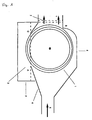
- the air flow impinges laterally on the drum, as sketched in the drawing.
- the air flow 5 exits a relatively narrow tube, which widens to the guide housing 4, whereby the air flow is slowed down.
- This then flows twice through the wire nets 1, once in the area AB, and then again in the area BC. He loads himself with the soap solution 3 and forms soap bubbles.
- These rupture on a grid arranged behind 7.
- This grid can be formed in various ways, for example as a tight-meshed wire mesh or as a perforated plate. It is essential that the grid is permeable to air but not to the liquid soap solution.
- the cleaned air stream 6 leaves the device; the soap solution loaded with the impurities runs into the storage container 2, from which it can be withdrawn.
- the essence of the invention is to be seen in the fact that the air flow to be cleaned is passed through the wire nets, so that soap bubbles form on the meshes, on the walls of which the contaminants accumulate and are transported into the bath.
- the contents of the bath are removed continuously or intermittently and fresh soap solution is added to the bath.
- the liquid lost due to evaporation is also replaced.
- the impurities e.g. removed by sedimentation or filtration.
- Gaseous contaminants are conveniently added in the bath to solids, e.g. Adsorbed polymers. After removal from the bath, they can be desorbed by acid treatment and the polymers returned to the bath.
Landscapes
- Chemical & Material Sciences (AREA)
- Chemical Kinetics & Catalysis (AREA)
- Engineering & Computer Science (AREA)
- Environmental & Geological Engineering (AREA)
- Health & Medical Sciences (AREA)
- Biomedical Technology (AREA)
- Analytical Chemistry (AREA)
- General Chemical & Material Sciences (AREA)
- Oil, Petroleum & Natural Gas (AREA)
- Separation Of Particles Using Liquids (AREA)
- Electrostatic Separation (AREA)
- Gas Separation By Absorption (AREA)
Description
- Die Erfindung betrifft ein Verfahren zum Entfernen von festen, flüssigen oder gasförmigen Verunreinigungen aus einem Luft- oder Abluftstrom, bei dem der Luftstrom mit einer Flüssigkeit in Kontakt gebracht wird, in der sich die Verunreinigungen ansammeln, und aus der sie entfernt werden.
- Luft- und Abluftströme im industriellen Bereich, aber auch in Gebäuden sind häufig durch feste oder flüssige Partikel oder durch Gase verunreinigt, die zu Umweltbelastung und Geruchsbelästigung führen. Typische Beispiele sind:
- Stäube, die z.B. beim Mahlen, Sieben, Trocknen und Fördern anfallen;
- Rauch, der bei Verbrennungsprozessen oder beim Tabakgenuss entsteht;
- Aerosole und Oversprays, die bei chemischen Prozessen, z.B. bei der Herstellung von Düngemitteln, und in Lackieranlagen anfallen;
- Nebel, der z.B. bei der Säureherstellung oder beim Farbsprühen entsteht;
- Gase, z.B. Ammoniak, Amine und Schwefelwasserstoff, die bei chemischen Reaktionen oder im Wohnbereich entstehen, sowie flüchtige organische Verbindungen, wie z.B. Kohlenwasserstoffe.
- Seit Beginn des industriellen Zeitalters wurden verschiedene Methoden zur Abluftreinigung entwickelt. Diese reichen von mechanischen Staub- und Aerosolabscheidern, Tuchfiltem und Flüssigkeitswäschern bis zu elektrostatischer Abscheidung. Zur Gaswäsche sind Absorptions- und Kondensationsprozesse üblich. Weiterhin sind, z.B. aus der WO-A-9214537, Verfahren und eine Vorrichtung zum Reinigen von mit Schadstoffen beladenen Gasen, wobei die Gase durch mindestens ein mit einem Schaumbildner versetztes wässriges Schäumbad geleitet werden.
- Alle genannten Methoden sind aber mit Nachteilen verbunden: einige sind für die Feinreinigung unzureichend, andere sind sehr aufwendig und teuer, die meisten sind eng begrenzt auf die Reinigung sehr spezieller Abluftströme zugeschnitten.
- Der Erfindung lag also die Aufgabe zugrunde, ein Verfahren zur Entfernung von Verunreinigungen aus Luft- und Abluftströmen zu entwickeln, das hochwirksam arbeitet, einfach und billig durchführbar ist und bei verschiedenartigen festen, flüssigen und gasförmigen Verunreinigungen angewandt werden kann. Eine weitere Aufgabe bestand darin, ein Verfahren bereitzustellen, welches die Erfüllung der immer schärfer werdenden gesetzlichen Auflagen und Grenzwerte für die Luftreinheit ermöglicht.
- Diese Aufgaben werden durch das erfindungsgemäße Verfahren nach Anspruch 1 gelöst. Ein weitere Gegenstand der Erfindung ist eine Vorrichtungen zur Durchführung dieses Verfahrens nach Anspruch 13.
- Das erfindungsgemäße Verfahren ist sowohl im industriellen Bereich beim Reinigen der Abluft aus Kaminen als auch bei der Luftwäsche in Gebäuden anwendbar. Bei Kaminen kann die erfindungsgemäße Vorrichtung entweder am oberen Kaminende angebracht sein, vorzugsweise ist sie als Bypass ausgelegt, wobei der Abluftstrom seitlich abgezogen, durch die Reinigungsvorrichtung geführt und weiter oben wieder in den Kamin eingeleitet wird. Bei der Beseitigung von Gerüchen und schlechter Luft in Gebäuden, z.B. Krankenhäusern, Gaststätten, Großküchen und Fabrikhallen wird durch ein Gebläse die Luft angesaugt, durch die Reinigungsvorrichtung geführt, dort gereinigt und wieder in den Raum zurückgeleitet. Das Verfahren kann auch als zusätzliche Maßnahme bei konventionellen Geräten zur Luftwäsche angewandt werden, um deren Effizienz zu verbessern. So kann die erfindungsgemäße Vorrichtung z. B. üblichen Venturi-Wäschern nachgeschaltet werden.
- Das Verfahren kann zur Entfernung der verschiedenartigsten Verunreinigungen angewandt werden:
- feste Verunreinigungen, z.B. Stäube, mit einer Partikelgröße von 1 bis 30µm;
- feste Verunreinigungen, wie z.B. Aerosole, Oversprays oder Rauchpartikel mit einer Partikelgröße von kleiner als 1 µm, vorzugsweise kleiner als 0,1 µm;
- flüssige Verunreinigungen, wie Nebel mit einer Größe von weniger als 10 µm;
- gasförmige Verunreinigungen.
- Bei dem erfindungsgemäßen Verfahren wird der Luftstrom durch ein oder mehrere trommelförmig zusammen gebogene Drahtnetze geführt, die horizontal liegend angeordnet sind, sich um die Achse der Trommel drehen, mit der Seifenlösung beladen sind und in ein mit Seifenlösung gefülltes Bad eintauchen. Der Trommeldurchmesser der Drahtnetze kann zwischen 10 und 200 cm liegen, ihre Länge beträgt vorzugsweise 20 bis 500 cm. Die Drahtnetze können aus Metalldrähten oder Glasfaserbündeln, die gegebenenfalls mit Kunststoff beschichtet sind, oder aus Kunststoffdrähten bestehen; die Maschenweite beträgt vorzugsweise 5 bis 50 mm. Die Maschen können z.B. dreieckige, viereckige, sechseckige oder achteckige Form haben oder auch dreidimensional mit Vor- und Rücksprüngen konstruiert sein. Bevorzugt sind mehrere, z. B. zwei bis fünf trommelförmige Drahtnetze konzentrisch ineinander angeordnet; es ist auch möglich, mehrere Drahtnetze hintereinander anzuordnen. Die Drahtnetze tauchen in ein Bad mit z.B. 0,1 bis 5%iger Seifenlösung ein, wobei die Eintauchtiefe vorzugsweise 1/10 bis 4/10 des Trommeldurchmessers beträgt. Die Trommel dreht sich um ihre Achse, so dass die Drahtnetze stets mit Seifenlösung beladen werden.
- Für das Einführen des Luftstroms in die Drahtnetze sind mehrere Varianten möglich. Bei einer ersten, bevorzugten Methode trifft der Luftstrom seitlich auf die Trommel auf, wie es in der Zeichnung skizziert ist. Der Luftstrom 5 tritt dabei aus einem relativ engen Rohr aus, welches sich zu dem Führungsgehäuse 4 ausweitet, wodurch der Luftstrom verlangsamt wird. Dieser durchströmt dann zweimal die Drahtnetze 1, einmal im Bereich AB, und dann noch einmal im Bereich BC. Dabei belädt er sich mit der Seifenlösung 3 und bildet Seifenblasen. Diese platzen an einem dahinter angeordneten Gitter 7. Dieses Gitter kann auf verschiedenartige Weise ausgeformt sein, z.B. als engmaschiges Drahtnetz oder als Lochblech. Wesentlich ist, dass das Gitter für Luft, aber nicht für die flüssige Seifenlösung durchlässig ist. Der gereinigte Luftstrom 6 verlässt die Vorrichtung; die mit den Verunreinigungen beladenen Seifenlösung läuft in den Vorratsbehälter 2, aus dem sie abgezogen werden kann.
- Der Kern der Erfindung ist darin zu sehen, dass der zu reinigende Luftstrom durch die Drahtnetze geführt wird, so dass sich an den Maschen Seifenblasen bilden, an deren Wände sich die Verunreinigungen ansammeln und in das Bad befördert werden. Der Inhalt des Bades wird kontinuierlich oder absatzweise abgeführt und frische Seifenlösung wird in das Bad zugeführt. Dabei wird auch die durch Verdunstung verloren gegangene Flüssigkeit wieder ersetzt. Aus der abgezogenen Seifenlösung werden die Verunreinigungen, z.B. durch Sedimentieren oder Filtrieren entfernt. Gasförmige Verunreinigungen werden zweckmäßigerweise im Bad an Feststoffen, z.B. Polymeren adsorbiert. Nach dem Entfernen aus dem Bad können sie durch Säurebehandlung desorbiert und die Polymeren wieder in das Bad zurückgeführt werden.
- Bei einer nach der skizzierten Ausführungsform konstruierten Pilotanlage wurden aus dem Kamin einer Ammoniumnitratfabrik 5000 m3 Abluft pro Stunde abgezogen. Mehr als 70% der Verunreinigungen, die im wesentlichen aus kristallförmigen Aerosolen mit einer Partikelgröße von etwa 0,1µm bestanden, wurden aus der Abluft entfernt.
Claims (13)
- Verfahren zum Entfernen von Verunreinigungen aus einem Luft- oder Abluftstrom, bei dem der Luftstrom mit Seifenblasen in Kontakt gebracht wird, an denen sich die Verunreinigungen ansammeln und aus denen sie entfernt werden, dadurch gekennzeichnet,- dass der Luftstrom durch ein oder mehrere trommelförmig zusammen gebogene, horizontal liegende, sich um die Trommelachse drehende Drahtnetze geführt wird, die in ein darunter angeordneten Bad mit einer Seifenlösung eintauchen und dort mit dieser beladen werden,- dass sich an den Maschen des Drahtnetzes durch den Luftstrom Seifenblasen bilden, an deren Wände sich die Verunreinigungen ansammeln, und die an einem hinter dem Drahtnetz angeordneten Gitter platzen,- dass die dabei gebildete Seifenlösung mit den Verunreinigungen wieder in das Bad abfließt,- und dass der Inhalt des Bades kontinuierlich oder absatzweise abgeführt wird, und die Verunreinigungen daraus entfernt werden, und in gleichem Maße frische Seifenlösung in das Bad zugeführt wird.
- Verfahren nach Anspruch 1, dadurch gekennzeichnet, dass mehrere trommelförmige Drahtnetze konzentrisch ineinander angeordnet sind.
- Verfahren nach Anspruch 1, dadurch gekennzeichnet, dass mehrere Drahtnetze bzw. Gruppen von Drahtnetzen hintereinander angeordnet sind.
- Verfahren nach Anspruch 1, dadurch gekennzeichnet, dass die Maschenweite der Drahtnetze 5 bis 50 mm beträgt.
- Verfahren nach Anspruch 1, dadurch gekennzeichnet, dass die Drahtnetze aus Metalldrähten oder Glasfaserbündeln, die gegebenenfalls mit Kunststoff beschichtet sind, oder aus Kunststoffdrähten bestehen.
- Verfahren nach Anspruch 6, dadurch gekennzeichnet, dass die Eintauchtiefe der Drahtnetze 1/10 bis 4/10 des Trommeldurchmessers beträgt.
- Verfahren zur Entfernung von Verunreinigungen aus der Abluft von Kaminen, dadurch gekennzeichnet, dass die Abluft aus dem Kamin seitlich abgezogen, nach Anspruch 1 gereinigt und die gereinigte Luft wieder in den Kamin zurückgeführt wird, oder dass die Abluft am oberen Ende des Kamins nach Anspruch 1 gereinigt wird.
- Verfahren zur Entfernung von Verunreinigungen aus der Luft von Gebäuden, dadurch gekennzeichnet, dass die Luft aus dem Raum abgesaugt, nach Anspruch 1 gereinigt und die gereinigte Luft wieder in den Raum zurückgeführt wird.
- Verfahren nach Anspruch 1, dadurch gekennzeichnet, dass gasförmige Verunreinigungen entfernt werden.
- Verfahren nach Anspruch 1, dadurch gekennzeichnet, dass flüssige Verunreinigungen mit einer Partikelgröße von kleiner als 10 µm. z.B. Nebel, entfernt werden.
- Verfahren nach Anspruch 1, dadurch gekennzeichnet, dass feste Verunreinigungen mit einer Partikelgröße von kleiner als 1 µm, z.B. Aerosole, Oversprays oder Rauchpartikel entfernt werden.
- Verfahren nach Anspruch 1, dadurch gekennzeichnet, dass feste Verunreinigungen mit einer Partikelgröße von 1 bis 30 µm. z.B. Stäube, entfernt werden.
- Vorrichtung zur Durchführung des Verfahrens nach Anspruch 1, gekennzeichnet durch folgende Bestandteile:- ein trommelförmig zusammengebogenes, horizontal liegendes, um seine Achse drehbares Drahtnetz 1 bzw. mehrere, konzentrisch ineinander angeordnete Drahtnetze,- ein Vorratsbehälter 2 mit Seifenlösung 3, in den das Drahtnetz eintaucht,- ein Führungsgehäuse 4 für den Luftstrom, das um das Drahtnetz herum angebracht ist,- mit einem Eintrittsbereich 5 und einem Austrittsbereich 6 für den Luftstrom,- sowie ein Gitter 7 am Austrittsbereich, das für Luft, aber nicht für die Seifenlösung durchlässig ist.
Applications Claiming Priority (2)
| Application Number | Priority Date | Filing Date | Title |
|---|---|---|---|
| DE10154312A DE10154312A1 (de) | 2001-11-05 | 2001-11-05 | Verfahren zum Entfernen von Verunreinigungen aus einem Luft- oder Abluftstrom |
| DE10154312 | 2001-11-05 |
Publications (2)
| Publication Number | Publication Date |
|---|---|
| EP1308197A1 EP1308197A1 (de) | 2003-05-07 |
| EP1308197B1 true EP1308197B1 (de) | 2007-05-30 |
Family
ID=7704690
Family Applications (1)
| Application Number | Title | Priority Date | Filing Date |
|---|---|---|---|
| EP02024314A Expired - Lifetime EP1308197B1 (de) | 2001-11-05 | 2002-11-02 | Verfahren und Vorrichtung zum Entfernen von Verunreinigungen aus einem Luft-oder Abluftstrom |
Country Status (4)
| Country | Link |
|---|---|
| EP (1) | EP1308197B1 (de) |
| AT (1) | ATE363331T1 (de) |
| DE (2) | DE10154312A1 (de) |
| ES (1) | ES2287213T3 (de) |
Families Citing this family (1)
| Publication number | Priority date | Publication date | Assignee | Title |
|---|---|---|---|---|
| DE10244419A1 (de) * | 2002-09-24 | 2004-04-01 | Gkss-Forschungszentrum Geesthacht Gmbh | Gestützte Schaumfilm-Membranen für die Gas-Separation |
Family Cites Families (10)
| Publication number | Priority date | Publication date | Assignee | Title |
|---|---|---|---|---|
| DE383794C (de) * | 1923-10-18 | Hermann Klug | Gaswascher | |
| BE755871A (fr) * | 1969-09-10 | 1971-03-08 | Merrill Edward Wilson | Procede pour debarrasser un gaz non organique d'impuretes organiques qui le polluent |
| US3830041A (en) * | 1971-10-20 | 1974-08-20 | Environeering | Foam breaker |
| DE3021606A1 (de) * | 1980-06-09 | 1981-12-17 | Howard W. Mountain Lakes N.J. Cole jun. | Vorrichtung zum erzeugen von kleinblasigem schaum |
| CA1206865A (en) * | 1981-04-13 | 1986-07-02 | Evan E. Koslow | Energy efficient phase transfer/dispersion systems and methods for using the same |
| DE4104285A1 (de) * | 1991-02-13 | 1992-08-20 | Henninger Geier Waltraud | Verfahren und vorrichtung zum reinigen von mit schadstoffen beladenen gasen |
| US5378264A (en) * | 1992-12-02 | 1995-01-03 | Aluminum Company Of America | Microemulsion formation in offgas scrubbing |
| DE4308842A1 (de) * | 1993-03-19 | 1994-09-22 | Peter Prof Dr Walzel | Verfahren und Vorrichtung zum Zerstäuben von Flüssigkeiten |
| JPH0957040A (ja) * | 1995-08-29 | 1997-03-04 | Babcock Hitachi Kk | 脱塵方法と装置 |
| DE19831507A1 (de) * | 1998-07-14 | 2000-02-03 | Climarotec Ges Fuer Raumklimat | Adsorption von hydrophoben Gaskomponenten und/oder Aerosolen aus einer Gasphase mittels eines mit Tensiden angereicherten Flüssigkeitsnebels |
-
2001
- 2001-11-05 DE DE10154312A patent/DE10154312A1/de not_active Withdrawn
-
2002
- 2002-11-02 ES ES02024314T patent/ES2287213T3/es not_active Expired - Lifetime
- 2002-11-02 DE DE50210228T patent/DE50210228D1/de not_active Expired - Lifetime
- 2002-11-02 AT AT02024314T patent/ATE363331T1/de not_active IP Right Cessation
- 2002-11-02 EP EP02024314A patent/EP1308197B1/de not_active Expired - Lifetime
Also Published As
| Publication number | Publication date |
|---|---|
| DE10154312A1 (de) | 2003-05-15 |
| ES2287213T3 (es) | 2007-12-16 |
| ATE363331T1 (de) | 2007-06-15 |
| DE50210228D1 (de) | 2007-07-12 |
| EP1308197A1 (de) | 2003-05-07 |
Similar Documents
| Publication | Publication Date | Title |
|---|---|---|
| KR101923502B1 (ko) | 배기가스 정화방법 및 그에 의한 배기가스 정화시스템 | |
| CA2766124C (en) | Process and system for separating finely aerosolized elemental mercury from gaseous streams | |
| EP3834906B1 (de) | Vorrichtung und verfahren zur abtrennung von schwebstoffen aus gasströmen | |
| JPH04227075A (ja) | ダスト及び汚染物質を含んだ排ガスを浄化する方法及び装置 | |
| EP0778067B1 (de) | Anlage zur Reinigung von Rauchgasen mit unterschiedlichen Gehalten an sauren Komponenten und Verfahren zum Betrieb der Anlage | |
| US8828731B2 (en) | Method and system for analyzing concentrations of diverse mercury species present in a fluid medium | |
| EP1447122B1 (de) | Verfahren und Vorrichtung zur Reduzierung des aerosolbedingten Austrages aus einer Trennkolonne | |
| EP0188853A1 (de) | Verfahren und Vorrichtung zum Reinigen der aus eienem Kremationsofen herkunftigen Luft | |
| EP0101556B1 (de) | Vorrichtung zur Reinigung radioaktiver Abgase | |
| CN207203660U (zh) | 一种立式除雾器 | |
| US9504946B2 (en) | Process and system for separating finely aerosolized elemental mercury from gaseous streams | |
| EP1308197A1 (de) | Verfahren zum Entfernen von Verunreinigungen aus einem Luft-oder Abluftstrom | |
| DE8424381U1 (de) | Adsorptionsvorrichtung zum reinigen von gasen | |
| DE60124352T2 (de) | Verfahren und Vorrichtung zur Entfernung von Schwefelsäurenebel aus Gasen | |
| Agranovski et al. | Case study on the practical use of wettable filters in the removal of submicron particles | |
| DE2813403C2 (de) | Verfahren zum Reinigen von Dämpfen | |
| WO2007014615A1 (de) | Kunststoffrohr für nasselektrofilter sowie bausatz für eine abgasreinigungsanlage | |
| EP3191214B1 (de) | Verfahren und system zur abscheidung von fein aerosolisiertem elementarem quecksilber aus gasströmen | |
| DE10249785B4 (de) | Öl- und Emulsionsnebel-Abscheider | |
| DE102022105258A1 (de) | Vorrichtung und Verfahren zur Reinigung eines Gasstromes | |
| EP0972556A1 (de) | Adsorption von hydrophoben Gaskomponenten und/oder Aerosolen aus einer Gasphase | |
| EP1151784A1 (de) | Luftfiltervorrichtung | |
| JP2769324B2 (ja) | 排ガス処理装置 | |
| CN211025784U (zh) | 一种污泥废气洗涤塔 | |
| Paur et al. | Removal of the aerosol formed in the electron beam dry scrubbing process by bag filters |
Legal Events
| Date | Code | Title | Description |
|---|---|---|---|
| PUAI | Public reference made under article 153(3) epc to a published international application that has entered the european phase |
Free format text: ORIGINAL CODE: 0009012 |
|
| AK | Designated contracting states |
Designated state(s): AT BE BG CH CY CZ DE DK EE ES FI FR GB GR IE IT LI LU MC NL PT SE SK TR |
|
| AX | Request for extension of the european patent |
Extension state: AL LT LV MK RO SI |
|
| 17P | Request for examination filed |
Effective date: 20030502 |
|
| AKX | Designation fees paid |
Designated state(s): AT BE BG CH CY CZ DE DK EE ES FI FR GB GR IE IT LI LU MC NL PT SE SK TR |
|
| 17Q | First examination report despatched |
Effective date: 20060705 |
|
| GRAP | Despatch of communication of intention to grant a patent |
Free format text: ORIGINAL CODE: EPIDOSNIGR1 |
|
| RTI1 | Title (correction) |
Free format text: PROCESS AND APPARATUS FOR REMOVING POLLUTANTS FROM AN AIR STREAM |
|
| GRAS | Grant fee paid |
Free format text: ORIGINAL CODE: EPIDOSNIGR3 |
|
| GRAA | (expected) grant |
Free format text: ORIGINAL CODE: 0009210 |
|
| AK | Designated contracting states |
Kind code of ref document: B1 Designated state(s): AT BE BG CH CY CZ DE DK EE ES FI FR GB GR IE IT LI LU MC NL PT SE SK TR |
|
| PG25 | Lapsed in a contracting state [announced via postgrant information from national office to epo] |
Ref country code: FI Free format text: LAPSE BECAUSE OF FAILURE TO SUBMIT A TRANSLATION OF THE DESCRIPTION OR TO PAY THE FEE WITHIN THE PRESCRIBED TIME-LIMIT Effective date: 20070530 |
|
| REG | Reference to a national code |
Ref country code: GB Ref legal event code: FG4D Free format text: NOT ENGLISH |
|
| REG | Reference to a national code |
Ref country code: CH Ref legal event code: EP |
|
| REG | Reference to a national code |
Ref country code: IE Ref legal event code: FG4D Free format text: LANGUAGE OF EP DOCUMENT: GERMAN |
|
| REF | Corresponds to: |
Ref document number: 50210228 Country of ref document: DE Date of ref document: 20070712 Kind code of ref document: P |
|
| PG25 | Lapsed in a contracting state [announced via postgrant information from national office to epo] |
Ref country code: SE Free format text: LAPSE BECAUSE OF FAILURE TO SUBMIT A TRANSLATION OF THE DESCRIPTION OR TO PAY THE FEE WITHIN THE PRESCRIBED TIME-LIMIT Effective date: 20070830 |
|
| ET | Fr: translation filed | ||
| NLV1 | Nl: lapsed or annulled due to failure to fulfill the requirements of art. 29p and 29m of the patents act | ||
| REG | Reference to a national code |
Ref country code: ES Ref legal event code: FG2A Ref document number: 2287213 Country of ref document: ES Kind code of ref document: T3 |
|
| GBV | Gb: ep patent (uk) treated as always having been void in accordance with gb section 77(7)/1977 [no translation filed] |
Effective date: 20070530 |
|
| REG | Reference to a national code |
Ref country code: IE Ref legal event code: FD4D |
|
| PG25 | Lapsed in a contracting state [announced via postgrant information from national office to epo] |
Ref country code: BG Free format text: LAPSE BECAUSE OF FAILURE TO SUBMIT A TRANSLATION OF THE DESCRIPTION OR TO PAY THE FEE WITHIN THE PRESCRIBED TIME-LIMIT Effective date: 20070830 Ref country code: CZ Free format text: LAPSE BECAUSE OF FAILURE TO SUBMIT A TRANSLATION OF THE DESCRIPTION OR TO PAY THE FEE WITHIN THE PRESCRIBED TIME-LIMIT Effective date: 20070530 Ref country code: IE Free format text: LAPSE BECAUSE OF FAILURE TO SUBMIT A TRANSLATION OF THE DESCRIPTION OR TO PAY THE FEE WITHIN THE PRESCRIBED TIME-LIMIT Effective date: 20070530 Ref country code: NL Free format text: LAPSE BECAUSE OF FAILURE TO SUBMIT A TRANSLATION OF THE DESCRIPTION OR TO PAY THE FEE WITHIN THE PRESCRIBED TIME-LIMIT Effective date: 20070530 Ref country code: PT Free format text: LAPSE BECAUSE OF FAILURE TO SUBMIT A TRANSLATION OF THE DESCRIPTION OR TO PAY THE FEE WITHIN THE PRESCRIBED TIME-LIMIT Effective date: 20071030 Ref country code: DK Free format text: LAPSE BECAUSE OF FAILURE TO SUBMIT A TRANSLATION OF THE DESCRIPTION OR TO PAY THE FEE WITHIN THE PRESCRIBED TIME-LIMIT Effective date: 20070530 |
|
| PG25 | Lapsed in a contracting state [announced via postgrant information from national office to epo] |
Ref country code: SK Free format text: LAPSE BECAUSE OF FAILURE TO SUBMIT A TRANSLATION OF THE DESCRIPTION OR TO PAY THE FEE WITHIN THE PRESCRIBED TIME-LIMIT Effective date: 20070530 |
|
| PLBE | No opposition filed within time limit |
Free format text: ORIGINAL CODE: 0009261 |
|
| STAA | Information on the status of an ep patent application or granted ep patent |
Free format text: STATUS: NO OPPOSITION FILED WITHIN TIME LIMIT |
|
| PG25 | Lapsed in a contracting state [announced via postgrant information from national office to epo] |
Ref country code: GR Free format text: LAPSE BECAUSE OF FAILURE TO SUBMIT A TRANSLATION OF THE DESCRIPTION OR TO PAY THE FEE WITHIN THE PRESCRIBED TIME-LIMIT Effective date: 20070831 Ref country code: GB Free format text: LAPSE BECAUSE OF FAILURE TO SUBMIT A TRANSLATION OF THE DESCRIPTION OR TO PAY THE FEE WITHIN THE PRESCRIBED TIME-LIMIT Effective date: 20070530 Ref country code: IT Free format text: LAPSE BECAUSE OF FAILURE TO SUBMIT A TRANSLATION OF THE DESCRIPTION OR TO PAY THE FEE WITHIN THE PRESCRIBED TIME-LIMIT Effective date: 20070530 |
|
| 26N | No opposition filed |
Effective date: 20080303 |
|
| BERE | Be: lapsed |
Owner name: WUEST, ROBERT Effective date: 20071130 |
|
| PG25 | Lapsed in a contracting state [announced via postgrant information from national office to epo] |
Ref country code: MC Free format text: LAPSE BECAUSE OF NON-PAYMENT OF DUE FEES Effective date: 20071130 |
|
| PG25 | Lapsed in a contracting state [announced via postgrant information from national office to epo] |
Ref country code: CH Free format text: LAPSE BECAUSE OF NON-PAYMENT OF DUE FEES Effective date: 20071130 Ref country code: LI Free format text: LAPSE BECAUSE OF NON-PAYMENT OF DUE FEES Effective date: 20071130 |
|
| REG | Reference to a national code |
Ref country code: CH Ref legal event code: PL |
|
| PG25 | Lapsed in a contracting state [announced via postgrant information from national office to epo] |
Ref country code: BE Free format text: LAPSE BECAUSE OF NON-PAYMENT OF DUE FEES Effective date: 20071130 |
|
| PG25 | Lapsed in a contracting state [announced via postgrant information from national office to epo] |
Ref country code: EE Free format text: LAPSE BECAUSE OF FAILURE TO SUBMIT A TRANSLATION OF THE DESCRIPTION OR TO PAY THE FEE WITHIN THE PRESCRIBED TIME-LIMIT Effective date: 20070530 |
|
| PG25 | Lapsed in a contracting state [announced via postgrant information from national office to epo] |
Ref country code: AT Free format text: LAPSE BECAUSE OF NON-PAYMENT OF DUE FEES Effective date: 20071102 |
|
| PG25 | Lapsed in a contracting state [announced via postgrant information from national office to epo] |
Ref country code: CY Free format text: LAPSE BECAUSE OF FAILURE TO SUBMIT A TRANSLATION OF THE DESCRIPTION OR TO PAY THE FEE WITHIN THE PRESCRIBED TIME-LIMIT Effective date: 20070530 |
|
| PG25 | Lapsed in a contracting state [announced via postgrant information from national office to epo] |
Ref country code: LU Free format text: LAPSE BECAUSE OF NON-PAYMENT OF DUE FEES Effective date: 20071102 |
|
| PG25 | Lapsed in a contracting state [announced via postgrant information from national office to epo] |
Ref country code: TR Free format text: LAPSE BECAUSE OF FAILURE TO SUBMIT A TRANSLATION OF THE DESCRIPTION OR TO PAY THE FEE WITHIN THE PRESCRIBED TIME-LIMIT Effective date: 20070530 |
|
| PGFP | Annual fee paid to national office [announced via postgrant information from national office to epo] |
Ref country code: DE Payment date: 20101119 Year of fee payment: 9 |
|
| PGFP | Annual fee paid to national office [announced via postgrant information from national office to epo] |
Ref country code: ES Payment date: 20101130 Year of fee payment: 9 |
|
| REG | Reference to a national code |
Ref country code: DE Ref legal event code: R119 Ref document number: 50210228 Country of ref document: DE Effective date: 20120601 |
|
| REG | Reference to a national code |
Ref country code: ES Ref legal event code: FD2A Effective date: 20130604 |
|
| PG25 | Lapsed in a contracting state [announced via postgrant information from national office to epo] |
Ref country code: DE Free format text: LAPSE BECAUSE OF NON-PAYMENT OF DUE FEES Effective date: 20120601 |
|
| PG25 | Lapsed in a contracting state [announced via postgrant information from national office to epo] |
Ref country code: ES Free format text: LAPSE BECAUSE OF NON-PAYMENT OF DUE FEES Effective date: 20111103 |
|
| REG | Reference to a national code |
Ref country code: FR Ref legal event code: PLFP Year of fee payment: 14 |
|
| REG | Reference to a national code |
Ref country code: FR Ref legal event code: PLFP Year of fee payment: 15 |
|
| REG | Reference to a national code |
Ref country code: FR Ref legal event code: PLFP Year of fee payment: 16 |
|
| REG | Reference to a national code |
Ref country code: FR Ref legal event code: PLFP Year of fee payment: 17 |
|
| PGFP | Annual fee paid to national office [announced via postgrant information from national office to epo] |
Ref country code: FR Payment date: 20181029 Year of fee payment: 17 |
|
| PG25 | Lapsed in a contracting state [announced via postgrant information from national office to epo] |
Ref country code: FR Free format text: LAPSE BECAUSE OF NON-PAYMENT OF DUE FEES Effective date: 20191130 |