EP1307793B1 - Verfahren zum betrieb einer sicherheitsschaltvorrichtung und sicherheitsschaltvorrichtung - Google Patents
Verfahren zum betrieb einer sicherheitsschaltvorrichtung und sicherheitsschaltvorrichtung Download PDFInfo
- Publication number
- EP1307793B1 EP1307793B1 EP01956395A EP01956395A EP1307793B1 EP 1307793 B1 EP1307793 B1 EP 1307793B1 EP 01956395 A EP01956395 A EP 01956395A EP 01956395 A EP01956395 A EP 01956395A EP 1307793 B1 EP1307793 B1 EP 1307793B1
- Authority
- EP
- European Patent Office
- Prior art keywords
- microprocessors
- functions
- microprocessor
- safety switching
- processor
- Prior art date
- Legal status (The legal status is an assumption and is not a legal conclusion. Google has not performed a legal analysis and makes no representation as to the accuracy of the status listed.)
- Expired - Lifetime
Links
Images

Classifications
-
- G—PHYSICS
- G05—CONTROLLING; REGULATING
- G05B—CONTROL OR REGULATING SYSTEMS IN GENERAL; FUNCTIONAL ELEMENTS OF SUCH SYSTEMS; MONITORING OR TESTING ARRANGEMENTS FOR SUCH SYSTEMS OR ELEMENTS
- G05B19/00—Program-control systems
- G05B19/02—Program-control systems electric
- G05B19/04—Program control other than numerical control, i.e. in sequence controllers or logic controllers
- G05B19/042—Program control other than numerical control, i.e. in sequence controllers or logic controllers using digital processors
- G05B19/0428—Safety, monitoring
-
- G—PHYSICS
- G05—CONTROLLING; REGULATING
- G05B—CONTROL OR REGULATING SYSTEMS IN GENERAL; FUNCTIONAL ELEMENTS OF SUCH SYSTEMS; MONITORING OR TESTING ARRANGEMENTS FOR SUCH SYSTEMS OR ELEMENTS
- G05B19/00—Program-control systems
- G05B19/02—Program-control systems electric
- G05B19/04—Program control other than numerical control, i.e. in sequence controllers or logic controllers
- G05B19/042—Program control other than numerical control, i.e. in sequence controllers or logic controllers using digital processors
- G05B19/0421—Multiprocessor system
-
- G—PHYSICS
- G05—CONTROLLING; REGULATING
- G05B—CONTROL OR REGULATING SYSTEMS IN GENERAL; FUNCTIONAL ELEMENTS OF SUCH SYSTEMS; MONITORING OR TESTING ARRANGEMENTS FOR SUCH SYSTEMS OR ELEMENTS
- G05B2219/00—Program-control systems
- G05B2219/20—Pc systems
- G05B2219/22—Pc multi processor system
- G05B2219/2209—Only one processor is permitted to execute a common function at a time
-
- G—PHYSICS
- G05—CONTROLLING; REGULATING
- G05B—CONTROL OR REGULATING SYSTEMS IN GENERAL; FUNCTIONAL ELEMENTS OF SUCH SYSTEMS; MONITORING OR TESTING ARRANGEMENTS FOR SUCH SYSTEMS OR ELEMENTS
- G05B2219/00—Program-control systems
- G05B2219/20—Pc systems
- G05B2219/22—Pc multi processor system
- G05B2219/2212—All processors are loaded with same program, only part of program is used
-
- G—PHYSICS
- G05—CONTROLLING; REGULATING
- G05B—CONTROL OR REGULATING SYSTEMS IN GENERAL; FUNCTIONAL ELEMENTS OF SUCH SYSTEMS; MONITORING OR TESTING ARRANGEMENTS FOR SUCH SYSTEMS OR ELEMENTS
- G05B2219/00—Program-control systems
- G05B2219/20—Pc systems
- G05B2219/22—Pc multi processor system
- G05B2219/2217—First cluster runs normal program, second cluster runs different program
-
- G—PHYSICS
- G05—CONTROLLING; REGULATING
- G05B—CONTROL OR REGULATING SYSTEMS IN GENERAL; FUNCTIONAL ELEMENTS OF SUCH SYSTEMS; MONITORING OR TESTING ARRANGEMENTS FOR SUCH SYSTEMS OR ELEMENTS
- G05B2219/00—Program-control systems
- G05B2219/20—Pc systems
- G05B2219/22—Pc multi processor system
- G05B2219/2237—Selection of leader or follower
-
- G—PHYSICS
- G05—CONTROLLING; REGULATING
- G05B—CONTROL OR REGULATING SYSTEMS IN GENERAL; FUNCTIONAL ELEMENTS OF SUCH SYSTEMS; MONITORING OR TESTING ARRANGEMENTS FOR SUCH SYSTEMS OR ELEMENTS
- G05B2219/00—Program-control systems
- G05B2219/20—Pc systems
- G05B2219/24—Pc safety
- G05B2219/24194—One channel monitors correct programcode execution, other correct process state
-
- H—ELECTRICITY
- H01—ELECTRIC ELEMENTS
- H01H—ELECTRIC SWITCHES; RELAYS; SELECTORS; EMERGENCY PROTECTIVE DEVICES
- H01H47/00—Circuit arrangements not adapted to a particular application of the relay and designed to obtain desired operating characteristics or to provide energising current
- H01H47/002—Monitoring or fail-safe circuits
- H01H47/004—Monitoring or fail-safe circuits using plural redundant serial connected relay operated contacts in controlled circuit
Definitions
- the invention relates to a method for operating a Safety switching device and on such a safety switching device.
- a safety switching device is used in switchgear, to enable increased security.
- the safety switching device monitors an external electrical device and switches depending on the Monitoring result the energy supply to an electrical Device. Device and setup can be the same.
- the safety switching device is therefore both a monitoring function as well as a work function, for example the switching function.
- Under electrical equipment becomes both a single component and a Understand current or circuit.
- the switching circuit by means of the safety switching device and monitors the emergency stop circuit for a motor.
- the electrical device in this case would be the motor, i.e. a Consumer.
- the safety switching device switches in the Do not regulate the consumer directly, but indirectly via special switching devices.
- the safety switching device controls a consumer-specific switching device, for example a motor contactor or an auxiliary contactor for such a motor contactor.
- the safety switching device usually has one Circuit that takes over the monitoring function, and which includes electromechanical switching elements, for example Relay to interrupt the flow of current to said auxiliary contactor.
- electromechanical switching elements for example Relay to interrupt the flow of current to said auxiliary contactor.
- the safety switching device is also used as a safety combination designated.
- security combinations are the "SIGUARD” security combinations from Series 3TK28 from Siemens AG. These security combinations are based on a security device a programmable logic controller significantly less consuming.
- Such a safety device is very flexible and is used particularly in complex systems. It is programmed accordingly to the special Adjusted requirements and generally takes over also monitoring and control functions.
- An example for such a safety device is, for example "SIMATIC" series from Siemens AG.
- DE 43 42 991 A1 describes a method for monitoring a security redundant function, especially one fuel-heated device.
- two Microprocessors are provided after each startup of the device alternately from a master status to one Change slave status.
- this has the disadvantage that there is no redundancy during operation.
- the invention is based, as simple as possible Method for operating a safety switching device and the simplest possible safety switching device specify, with a high security level guaranteed is.
- the main element here is that the Microprocessors alternate different functions take.
- the two microprocessors run at the same time Therefore, never do the same routines. So that is achieved a so-called "dynamic" diversification.
- the redundancy as well as the diversity are ensured by one Run cycle reached during which the one microprocessor as the main processor (master) main functions and the other Microprocessor as secondary processor (slave) secondary functions takes over, and after a defined number of execution cycles the one microprocessor in the status of the slave processor and the other microprocessor in the status of Main processor changes.
- the alternate takeover of different So functions is at a certain cycle coupled.
- the main functions of the main processor are in particular the actual work functions the safety switching device, in particular the Switching function.
- the secondary functions are in particular monitoring functions.
- the main processor therefore acts as a "worker” while the slave processor serves as a "monitor".
- the microprocessors preferably take over as functions both a monitoring function and a work function, in particular a switching function by the control of an electronic switching element in the Take over the safety switching device.
- This electronic Switching element switches the power supply to the electrical one Device.
- the microprocessors all monitoring functions, i.e. both monitoring of the electrical external device or devices, as well internal monitoring of the safety switching device and the alternate monitoring of the microprocessors, performed. So the possibility of microprocessors, take on extensive and complex tasks within the framework the requirements of a safety switching device exhausted.
- the microprocessors have the same hardware construction.
- the microprocessors are therefore identical.
- microprocessors are also useful operated with the same operating software.
- the microprocessors are therefore preferably both in terms of your hardware as well as your software engineering structure identical. This has the advantage that confusing the microprocessors when assembling the safety switching device cannot occur. moreover is due to the uniform operating software in the event of changes or additions the adaptation of the operating software and the necessary documentation only once.
- the primary functions include in particular the work functions, whereas to the secondary functions for example monitoring the memory of the microprocessors or also performing certain device-specific tests counting.
- the division into primary functions and secondary functions is based on the consideration that not all possible Errors can be detected within the same period of time have to.
- the duration of the cycle is preferably shorter than 100ms and in particular less than 30ms. This ensures that, for example, after pressing an emergency stop button for the device until the interruption is triggered the power supply to the device through the switching element the maximum safety cycle device elapses the cycle time.
- each of the execution programs responsible for the execution of different functions and the sequential programs are synchronized with one another become. This prevents the execution cycles of the individual microprocessors diverge, and possibly one of the microprocessors already has the "master status" changes to "slave status" while the other Microprocessor is still in "slave status". In this case would be diversified at least for a period of time Training no longer carried out.
- microprocessors preferably together. Furthermore this communication is also used for data synchronization and data exchange. Conveniently, only one takes at a time of microprocessors play an active role.
- the synchronization is preferably carried out by communication of the two microprocessors with each other by both in the sequence program of the main processor as well as that of the secondary processor communication at the same time or in same time window is provided.
- One main processor is running something ahead, so he is necessarily in Program stopped and must wait for the other microprocessor is also ready for communication.
- the safety switching device determines which microprocessor initially as Main processor and which works as a secondary processor. In order to it is clearly and unambiguously determined who will be the first Main processor is.
- one of the two microprocessors initially as the main processor is selected. This can be compared in terms of design just solve, for example by using a corresponding pin assignment of one of the two microprocessors this is preconfigured accordingly. Alternatively is preferably dependent on the time of operational readiness the microprocessors made the selection. It offers itself, by a time delay with one the microprocessors to delay the startup a little. Usually the microprocessor comes on after startup a voltage reset is initiated, a defined initial state of the microprocessor to be achieved (power on reset, POR). It is only after the reset the microprocessor is ready for operation. Therefore, in particular for one of the two processors, this reset is comparatively executed late.
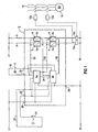
- a safety switching device 2 also referred to as a safety combination, comprises a first microprocessor 4a and a second microprocessor 4b as well as a total of four switching elements 6, which are designed in particular as electronic switching elements.
- the switching elements 6 are arranged in pairs 6a, 6b, a pair (6a, 6b) being arranged in series in a supply line 8 for an auxiliary contactor 10a, 10b.
- the auxiliary contactors 10a, 10b are thus electrical devices whose energy supply is switched directly by the safety switching device 2.
- Motor contactors 12a, 12b are actuated via the two auxiliary contactors 10a, 10b.
- motor contactors 12a, 12b serve to interrupt a three-phase network 14 for a consumer designed as a motor 16 and are also connected in series.
- the motor 16 is thus switched indirectly as an electrical device by the safety switching device 2.
- a switch-on circuit 18 with a switch 20 and a switch 22 with an emergency switch 24 are provided for switching the motor 16 on and off.
- Both the switch-on circuit 18 and the switch-off circuit 22 are each connected to the safety switching device 2 via connections 30 and 32, respectively. This is connected via supply connections 26, 28 to the positive potential L / + or to the negative potential N / - of a direct current source.
- the safety switching device 2 is operated with 24V.
- the two microprocessors 4a, 4b each stand with the two Connections 32 of the switching circuit 22 and with the two Connections 30 of the starting circuit 18 in connection. at the same time is each of the microprocessors 4a, 4b with each of the Switching elements 6 connected.
- the safety switching device 2 has several functions. On the one hand, it detects signals from the switch-on circuit 18 as well from the switch-off circuit 22 and transmits it to the engine 16 by operating the switching elements 6.
- the hereby related functions are called work functions AF.
- these two circuits 18, 20 monitors the electrical equipment in the sense of this application represent. For example, the two circuits 18.20 on short circuit to the positive potential L / + or the negative potential N / - or a conclusion monitored between the two circuits.
- the auxiliary contactors 10a, 10b and monitors the motor contactors 12a, 12b for operational safety become.
- the safety switching device takes 2 also have their own internal monitoring for example, the switching elements 6 on their Functionality monitored, as well as the two microprocessors 4a, 4b are checked and monitored. All Control and monitoring functions of the safety switching device 2 are in accordance with the embodiment of the two microprocessors 4a, 4b. For their own To check functionality, they are for a mutual Communication with each other via a communication link 34 connected. In addition, the two microprocessors take over 4a and 4b also the control of the individual electronic switching elements 6 via corresponding control lines 36th
- the two Microprocessors 4a, 4b alternately different functions perceive. This precludes the two Microprocessors 4a, 4b at any time Execute identical function routine.
- the two microprocessors 4a, 4b are both in terms of their hardware as well as in terms of their software engineering Structure identical. By alternately Taking on different functions is a quasi dynamic one diversified organization realized. Under software technology The operating software for understood the microprocessors, also referred to as firmware and usually in its read-only memory (ROM memory) is stored.
- the safety switching device 2 performs a multitude of functions. These can be divided into main functions and secondary functions, for example.
- the main functions are assigned, for example, the work functions AF and a first set of monitoring functions C1.
- the work functions include the detection of a switch-on or switch-off signal by the switch-on circuit 18 or switch-off circuit 22 and their further processing including activation of the switching elements 6.
- a second set C2 and further sets C x of monitoring functions are classified in the category of secondary functions. This division is not necessarily carried out in this way.
- the microprocessor that performs the main functions is referred to as a skin processor or master, where the other microprocessor, which processes the secondary functions, is referred to as a slave processor or slave.
- a first method step A which of the two microprocessors (e.g. 4a) as the main processor can be seen.
- the two Microprocessors 4a, 4b permanently provided as the main processor, see above that this always after the safety switching device has been commissioned occurs as the main processor.
- the microprocessors are initialized 4a and 4b.
- the safety switching device 2 is initialized and internal control of all of its components. Following this check is the safety switching device 2 ready for operation and the actual process cycle begins Z.
- a master specific Sequence program I or a slave-specific sequence program II started.
- the master-specific sequence program I first work through the work functions AF.
- Communication K with the next takes place second microprocessor (e.g. 4b) to exchange data or also for mutual control.
- the first set of control functions C1 is processed, then again at the end of the cycle a communication K.
- the implementation takes place the status from "master” to "slave”. This implementation can also only after a defined number of execution cycles Z done. Then the sequence cycle Z is again from started at the front.
- cycle Z is itself set to the status "slave" is therefore slave-specific in the new cycle Z Sequence program I started. This starts with communication K, at the same time as the first Communication K in the master-specific sequence program I takes place.
- secondary functions namely the second set of monitoring functions C2 and a further set of monitoring functions C x are processed.
- the second set of monitoring functions C2 differs in terms of each individual function from the first set of monitoring functions C1 as they are carried out in accordance with the master-specific sequence program I.
- the further set of monitoring functions C x contains so-called secondary functions, which are not carried out with every execution cycle Z.
- the work functions AF and the sets C1, C2 of monitoring functions represent primary functions which are carried out in each sequence cycle.
- main functions which are represented here in the exemplary embodiment by the work functions AF and the first set of monitoring functions C1
- secondary functions which are represented here by the second set C2 and the further set C x of monitoring functions, ensure that on the microprocessors 4a, 4b run different routines.
Landscapes
- Physics & Mathematics (AREA)
- General Physics & Mathematics (AREA)
- Engineering & Computer Science (AREA)
- Automation & Control Theory (AREA)
- Safety Devices In Control Systems (AREA)
- Air Bags (AREA)
- Keying Circuit Devices (AREA)
Description
- FIG 1
- ein schematisches und stark vereinfachtes Schaltbild einer Sicherheitsschaltvorrichtung mit einem Einschaltkreis und einem Ausschaltkreis für einen elektrischen Verbraucher, und
- FIG 2
- ein Ablaufbild eines Ablaufzyklusses in schematischer Darstellung.
Über die beiden Hilfsschütze 10a,10b werden Motorschütze 12a,12b betätigt. Diese Motorschütze 12a,12b dienen zur Unterbrechung eines Drehstromnetzes 14 für einen als Motor 16 ausgebildeten Verbraucher und sind ebenfalls in Serie geschalten. Damit wird der Motor 16 als elektrisches Gerät mittelbar von der Sicherheitsschaltvorrichtung 2 geschaltet. Zum Ein- und Ausschalten des Motors 16 ist ein Einschaltkreis 18 mit einem Einschalttaster 20 sowie ein Ausschaltkreis 22 mit einem Not-Austaster 24 vorgesehen. Sowohl der Einschaltkreis 18 als auch der Ausschaltkreis 22 sind jeweils an der Sicherheitsschaltvorrichtung 2 über Anschlüsse 30 bzw. 32 angeschlossen. Diese wird über Versorgungsanschlüsse 26,28 an das positive Potential L/+ bzw. an das negative Potential N/- einer Gleichstromquelle angeschlossen. In der Regel wird die Sicherheitsschaltvorrichtung 2 mit 24V betrieben.
Claims (16)
- Verfahren zum Betrieb einer Sicherheitsschaltvorrichtung (2), bei dem zumindest eine elektrische Einrichtung (18,22) überwacht und die Energieversorgung zu einem elektrischen Gerät (10a,10b) geschaltet wird, wobei Funktionen (AF,C1,C2,Cx) der Sicherheitsschaltvorrichtung (2) von zumindest zwei Mikroprozessoren (4a,4b) ausgeführt werden, die abwechselnd unterschiedliche Funktionen (AF,C1,C2,Cx) übernehmen, dadurch gekennzeichnet, dass ein Ablaufzyklus (Z) mit einer bestimmten Ablaufzeit vorgesehen ist, währenddessen der eine Mikroprozessor (4a,4b) als Hauptprozessor (Master) Hauptfunktionen (AF,C1) und der andere Mikroprozessor (4a,4b) als Nebenprozessor (Slave) Nebenfunktionen (C2,Cx) übernimmt, und wobei nach einem Ablaufzyklus (Z) oder nach einer definierten Anzahl von Ablaufzyklen (Z) der eine Mikroprozessor (4a,4b) in den Status des Nebenprozessors und der andere Mikroprozessor (4a,4b) in den Status des Hauptprözessors wechselt.
- Verfahren nach Anspruch 1, bei dem die Mikroprozessoren (4a,4b) sowohl eine Überwachungsfunktion (C1,C2,Cx) als auch eine Arbeitsfunktion (AF) durch Ansteuern eines elektronischen Schaltelements (6,6a,6b) übernehmen.
- Verfahren nach Anspruch 1 oder 2, bei dem Mikroprozessoren (4a,4b) mit dem gleichen Aufbau verwendet werden.
- Verfahren nach einem der vorhergehenden Ansprüche, bei dem die Mikroprozessoren (4a,4b) mit der gleichen Betriebssoftware arbeiten.
- Verfahren nach einem der vorhergehenden Ansprüche, bei dem während jedes Ablaufzyklusses (Z) bestimmte Primärfunktionen (GF,C1,C2) und zusätzlich optionale Sekundärfunktionen (Cx) ausgeführt werden, wobei während verschiedener Ablaufzyklen (Z) unterschiedliche Sekundärfunktionen (Cx) ausgeführt werden.
- Verfahren nach einem der vorhergehenden Ansprüche, bei dem die Zeitdauer des Ablaufzyklusses (Z) kleiner als 100ms , insbesondere kleiner als 30ms ist.
- Verfahren nach einem der vorhergehenden Ansprüche, bei dem vom Hauptprozessor (4a,4b) und vom Nebenprozessor (4a,4b) unterschiedliche Ablaufprogramme (I,II) während eines Ablaufzyklusses (Z) ausgeführt werden, wobei die Ablaufprogramme (I,II) miteinander synchronisiert werden.
- Verfahren nach einem der vorhergehenden Ansprüche, bei dem die Mikroprozessoren (4a,4b) miteinander kommunizieren.
- Verfahren nach den Ansprüchen 7 und 8, bei dem die Synchronisation durch die Kommunikation (K) der beiden Mikroprozessoren (4a,4b) miteinander erfolgt, indem sowohl im Ablaufprogramm (I) des Hauptprozessors (4a,4b) als auch in dem Ablaufprogramm (II) des Nebenprozessors (4a,4b) die Kommunikation (K) zum gleichen Zeitpunkt vorgesehen ist.
- Verfahren nach Anspruch 8 oder 9, bei dem am Ende des Ablaufzyklusses(Z) die Kommunikation (K) erfolgt.
- Verfahren nach einem der vorhergehenden Ansprüche, bei dem bei der Inbetriebnahme der Sicherheitsschaltvorrichtung (2) ermittelt wird, welcher Mikroprozessor (4a,4b) zunächst als Hauptprozessor und welcher als Nebenprozessor arbeitet.
- Verfahren nach Anspruch 11, bei dem einer der Mikroprozessoren (4a,4b) zunächst grundsätzlich als Hauptprozessor ausgewählt wird.
- Sicherheitsschaltvorrichtung (2) mit einem insbesondere elektronischen Schaltelement (6,6a,6b) zur Unterbrechung der Energieversorgung eines elektrischen Geräts (10a,10b) und mit zumindest zwei Mikroprozessoren (4a,4b), die jeweils mit zumindest einer elektrischen Einrichtung (18,22) zu deren Überwachung sowie mit dem Schaltelement (6,6a,6b) zu dessen Ansteuerung verbunden sind, wobei die Mikroprozessoren (4a,4b) derart ausgebildet sind, dass sie abwechselnd unterschiedliche Funktionen (AF,C1,C2,Cx) ausüben, dadurch gekennzeichnet, dass ein Ablaufzyklus (Z) mit einer bestimmten Zykluszeit vorgesehen ist, während dessen der erste Mikroprozessor (4a,4b) als Hauptprozessor (Master) Hauptfunktionen und der zweite Mikroprozessor (4a,4b) als Nebenprozessor (Slave) Nebenfunktionen übernimmt, und wobei nach einem Ablaufzyklus (Z) oder nach einer definierten Anzahl von Ablaufzyklen (Z) der erste Mikroprozessor(4a,4b) in den Status des Nebenprozessors und der zweite Mikroprozessor (4a,4b) in den Status des Hauptprozessors wechselt.
- Vorrichtung (2) nach Anspruch 13, bei der die Mikroprozessoren (4a,4b) den gleichen Aufbau aufweisen.
- Vorrichtung (2) nach Anspruch 13 oder 14, bei der die Mikroprozessoren (4a,4b) die gleiche Betriebssoftware aufweisen.
- Vorrichtung (2) nach einem der Ansprüche 13 bis 15, bei der die Mikroprozessoren (4a,4b) über eine Kommunikationsverbindung (34) miteinander verbunden sind.
Applications Claiming Priority (3)
| Application Number | Priority Date | Filing Date | Title |
|---|---|---|---|
| DE10038953 | 2000-08-09 | ||
| DE10038953A DE10038953A1 (de) | 2000-08-09 | 2000-08-09 | Verfahren zum Betrieb einer Sicherheitsschaltvorrichtung und Sicherheitsschaltvorrichtung |
| PCT/DE2001/002850 WO2002013388A2 (de) | 2000-08-09 | 2001-07-27 | Verfahren zum betrieb einer sicherheitsschaltvorrichtung und sicherheitsschaltvorrichtung |
Publications (2)
| Publication Number | Publication Date |
|---|---|
| EP1307793A2 EP1307793A2 (de) | 2003-05-07 |
| EP1307793B1 true EP1307793B1 (de) | 2004-03-17 |
Family
ID=7651904
Family Applications (1)
| Application Number | Title | Priority Date | Filing Date |
|---|---|---|---|
| EP01956395A Expired - Lifetime EP1307793B1 (de) | 2000-08-09 | 2001-07-27 | Verfahren zum betrieb einer sicherheitsschaltvorrichtung und sicherheitsschaltvorrichtung |
Country Status (5)
| Country | Link |
|---|---|
| EP (1) | EP1307793B1 (de) |
| JP (1) | JP2004506303A (de) |
| AT (1) | ATE262190T1 (de) |
| DE (2) | DE10038953A1 (de) |
| WO (1) | WO2002013388A2 (de) |
Cited By (1)
| Publication number | Priority date | Publication date | Assignee | Title |
|---|---|---|---|---|
| WO2007054187A1 (de) * | 2005-11-11 | 2007-05-18 | Pilz Gmbh & Co. Kg | Sicherheitsschaltvorrichtung zum fehlersicheren abschalten eines elektrischen verbrauchers |
Families Citing this family (4)
| Publication number | Priority date | Publication date | Assignee | Title |
|---|---|---|---|---|
| JP3944156B2 (ja) * | 2003-12-03 | 2007-07-11 | ファナック株式会社 | 非常停止回路 |
| DE102005061152B4 (de) * | 2005-12-21 | 2015-12-17 | Bosch Rexroth Ag | Vorrichtung und Verfahren zur sicherheitsgerichteten Abschaltung eines Segmentkreises in einem Feldbus |
| DE102010037714B3 (de) | 2010-09-22 | 2012-01-05 | Schneider Electric Automation Gmbh | Not-Aus-Modul-Anordnung |
| US10855072B2 (en) * | 2017-12-27 | 2020-12-01 | Shanghai Chenzhu Instrument Co., Ltd. | Intelligent safety relay and circuit applied thereby |
Family Cites Families (1)
| Publication number | Priority date | Publication date | Assignee | Title |
|---|---|---|---|---|
| DE4342991A1 (de) * | 1993-12-16 | 1995-06-22 | Bosch Gmbh Robert | Verfahren zum Überwachen wenigstens einer sicherheitsrelevanten Funktion eines Gerätes |
-
2000
- 2000-08-09 DE DE10038953A patent/DE10038953A1/de not_active Withdrawn
-
2001
- 2001-07-27 WO PCT/DE2001/002850 patent/WO2002013388A2/de not_active Ceased
- 2001-07-27 DE DE50101727T patent/DE50101727D1/de not_active Expired - Fee Related
- 2001-07-27 AT AT01956395T patent/ATE262190T1/de not_active IP Right Cessation
- 2001-07-27 EP EP01956395A patent/EP1307793B1/de not_active Expired - Lifetime
- 2001-07-27 JP JP2002518623A patent/JP2004506303A/ja not_active Abandoned
Cited By (2)
| Publication number | Priority date | Publication date | Assignee | Title |
|---|---|---|---|---|
| WO2007054187A1 (de) * | 2005-11-11 | 2007-05-18 | Pilz Gmbh & Co. Kg | Sicherheitsschaltvorrichtung zum fehlersicheren abschalten eines elektrischen verbrauchers |
| US7933104B2 (en) | 2005-11-11 | 2011-04-26 | Pilz Gmbh & Co. Kg | Safety switching apparatus for a failsafe disconnection of an electrical load |
Also Published As
| Publication number | Publication date |
|---|---|
| WO2002013388A2 (de) | 2002-02-14 |
| ATE262190T1 (de) | 2004-04-15 |
| EP1307793A2 (de) | 2003-05-07 |
| DE50101727D1 (de) | 2004-04-22 |
| JP2004506303A (ja) | 2004-02-26 |
| WO2002013388A3 (de) | 2002-04-25 |
| DE10038953A1 (de) | 2002-02-28 |
Similar Documents
| Publication | Publication Date | Title |
|---|---|---|
| EP2317410B1 (de) | Sicherheitssteuerung | |
| EP2315088B1 (de) | Sicherheitssteuerung | |
| EP2098926B1 (de) | Verfahren und Vorrichtung zum Programmieren und/oder Konfigurieren einer Sicherheitssteuerung | |
| DE102016100175B4 (de) | Robotersystem, welches mit einer Mehrzahl von Controllern vorgesehen ist, die eine Mehrzahl von Industrierobotern betätigen | |
| EP1341636B1 (de) | Verfahren zum verbinden mehrerer schweissgeräte sowie schweissgerät hierfür | |
| EP3657288B1 (de) | Sichere spannungsüberwachung | |
| EP2246756B1 (de) | Verfahren und Bediengerät zum Bedienen einer sicherheitsgerichteten industriellen Automatisierungskomponente | |
| WO2000000319A1 (de) | Bolzenschweisseinrichtung | |
| EP3491787B1 (de) | Reihenmodul, funktionsmodulanordnung und modular ausgebildete steuerungsanordnung | |
| DE10148810B4 (de) | Steuerungs- und Energieversorgungssystem für wenigstens zwei Flugzeugsitze | |
| DE102015114220B4 (de) | Werkzeugmaschine mit Funktion zur sicheren Steuerung von peripheren Vorrichtungen | |
| EP1364459B1 (de) | Sicherheitsschaltvorrichtung | |
| DE10152653A1 (de) | Vorrichtung zur eigensicheren redundanten Strom-Spannungsversorgung | |
| EP1484780A1 (de) | Ansteuervorrichtung für sicherheitskritische Komponenten und entsprechendes Verfahren | |
| EP2099164A1 (de) | Sicherheitsvorrichtung zur sicheren Ansteuerung angeschlossener Aktoren | |
| DE10326542A1 (de) | Betriebsverfahren und Steuerungsprogramm für eine Zentraleinheit eines Automatisierungssystems sowie Zentraleinheit eines Automatisierungssystems und Automatisierungssystem selbst | |
| CH618029A5 (de) | ||
| EP1887444A1 (de) | Prozesssteuerung | |
| EP1128241B1 (de) | Verfahren und Vorrichtung zur Sicherheitsüberwachung einer Steuereinrichtung | |
| EP3414637B1 (de) | Sicherheitsschaltvorrichtung | |
| DE10038953A1 (de) | Verfahren zum Betrieb einer Sicherheitsschaltvorrichtung und Sicherheitsschaltvorrichtung | |
| EP3841439B1 (de) | Automatisierungssystem zur überwachung eines sicherheitskritischen prozesses | |
| EP3143506B1 (de) | Verfahren und system zum zuweisen einer steuerberechtigung zu einem rechner | |
| EP1485765A2 (de) | Sensor-maschinen-interface und verfahren zu dessen betrieb | |
| EP4321949A1 (de) | Modulare steuerungseinrichtung |
Legal Events
| Date | Code | Title | Description |
|---|---|---|---|
| PUAI | Public reference made under article 153(3) epc to a published international application that has entered the european phase |
Free format text: ORIGINAL CODE: 0009012 |
|
| 17P | Request for examination filed |
Effective date: 20021111 |
|
| AK | Designated contracting states |
Designated state(s): AT BE CH CY DE DK ES FI FR GB GR IE IT LI LU MC NL PT SE TR |
|
| AX | Request for extension of the european patent |
Extension state: AL LT LV MK RO SI |
|
| GRAP | Despatch of communication of intention to grant a patent |
Free format text: ORIGINAL CODE: EPIDOSNIGR1 |
|
| GRAS | Grant fee paid |
Free format text: ORIGINAL CODE: EPIDOSNIGR3 |
|
| GRAA | (expected) grant |
Free format text: ORIGINAL CODE: 0009210 |
|
| AK | Designated contracting states |
Kind code of ref document: B1 Designated state(s): AT DE FR IT |
|
| REG | Reference to a national code |
Ref country code: IE Ref legal event code: FG4D Free format text: GERMAN |
|
| REF | Corresponds to: |
Ref document number: 50101727 Country of ref document: DE Date of ref document: 20040422 Kind code of ref document: P |
|
| LTIE | Lt: invalidation of european patent or patent extension |
Effective date: 20040317 |
|
| REG | Reference to a national code |
Ref country code: IE Ref legal event code: FD4D |
|
| ET | Fr: translation filed | ||
| PLBE | No opposition filed within time limit |
Free format text: ORIGINAL CODE: 0009261 |
|
| STAA | Information on the status of an ep patent application or granted ep patent |
Free format text: STATUS: NO OPPOSITION FILED WITHIN TIME LIMIT |
|
| 26N | No opposition filed |
Effective date: 20041220 |
|
| PGFP | Annual fee paid to national office [announced via postgrant information from national office to epo] |
Ref country code: AT Payment date: 20060614 Year of fee payment: 6 |
|
| PGFP | Annual fee paid to national office [announced via postgrant information from national office to epo] |
Ref country code: FR Payment date: 20060727 Year of fee payment: 6 |
|
| PGFP | Annual fee paid to national office [announced via postgrant information from national office to epo] |
Ref country code: IT Payment date: 20060731 Year of fee payment: 6 |
|
| PGFP | Annual fee paid to national office [announced via postgrant information from national office to epo] |
Ref country code: DE Payment date: 20060918 Year of fee payment: 6 |
|
| PG25 | Lapsed in a contracting state [announced via postgrant information from national office to epo] |
Ref country code: DE Free format text: LAPSE BECAUSE OF NON-PAYMENT OF DUE FEES Effective date: 20080201 |
|
| REG | Reference to a national code |
Ref country code: FR Ref legal event code: ST Effective date: 20080331 |
|
| PG25 | Lapsed in a contracting state [announced via postgrant information from national office to epo] |
Ref country code: AT Free format text: LAPSE BECAUSE OF NON-PAYMENT OF DUE FEES Effective date: 20070727 |
|
| PG25 | Lapsed in a contracting state [announced via postgrant information from national office to epo] |
Ref country code: FR Free format text: LAPSE BECAUSE OF NON-PAYMENT OF DUE FEES Effective date: 20070731 |
|
| PG25 | Lapsed in a contracting state [announced via postgrant information from national office to epo] |
Ref country code: IT Free format text: LAPSE BECAUSE OF NON-PAYMENT OF DUE FEES Effective date: 20070727 |