EP1306595A2 - Valve assembly - Google Patents
Valve assembly Download PDFInfo
- Publication number
- EP1306595A2 EP1306595A2 EP02023139A EP02023139A EP1306595A2 EP 1306595 A2 EP1306595 A2 EP 1306595A2 EP 02023139 A EP02023139 A EP 02023139A EP 02023139 A EP02023139 A EP 02023139A EP 1306595 A2 EP1306595 A2 EP 1306595A2
- Authority
- EP
- European Patent Office
- Prior art keywords
- valve
- bore
- axis
- passage
- valve assembly
- Prior art date
- Legal status (The legal status is an assumption and is not a legal conclusion. Google has not performed a legal analysis and makes no representation as to the accuracy of the status listed.)
- Granted
Links
Images


Classifications
-
- F—MECHANICAL ENGINEERING; LIGHTING; HEATING; WEAPONS; BLASTING
- F16—ENGINEERING ELEMENTS AND UNITS; GENERAL MEASURES FOR PRODUCING AND MAINTAINING EFFECTIVE FUNCTIONING OF MACHINES OR INSTALLATIONS; THERMAL INSULATION IN GENERAL
- F16K—VALVES; TAPS; COCKS; ACTUATING-FLOATS; DEVICES FOR VENTING OR AERATING
- F16K5/00—Plug valves; Taps or cocks comprising only cut-off apparatus having at least one of the sealing faces shaped as a more or less complete surface of a solid of revolution, the opening and closing movement being predominantly rotary
- F16K5/04—Plug valves; Taps or cocks comprising only cut-off apparatus having at least one of the sealing faces shaped as a more or less complete surface of a solid of revolution, the opening and closing movement being predominantly rotary with plugs having cylindrical surfaces; Packings therefor
- F16K5/0457—Packings
- F16K5/0478—Packings on the plug
Definitions
- the present invention relates generally to a valve assembly and, more particularly, to a valve assembly having a valve body with a valve element mounted therein to control product flow through the valve body.
- Valve assemblies are used in many different industries and in many different applications. Some applications require sterilization, such as in the medical industry or food industry, and others do not, such as in the petroleum industry, the powder products dispensation industry, the sewer industry, certain chemical industries, or any number of different industries.
- bulk containers for storing and transporting low density products are available in a vast array of sizes and shapes.
- such containers include a relatively rigid outer container or box of corrugated paper, or the like, and a flexible sealed inner bag or container.
- an interior of the inner container is typically sterilized or otherwise aseptically treated to avoid contamination.
- the inner bag or container of such bulk containers is formed from such a material as to not adversely affect the materials held within the bag. After the inner bag or container is filled, it is placed in the outer container. If properly filled and sealed, the bag will contain no air that may damage or otherwise adversely affect the product during storage.
- An aseptic valve assembly is typically arranged in operable combination with the inner bag and extends to an exterior of the outer container for mass containment and at-will distribution of the product. It is also known to use the valve assembly to fill the inner bag with product.
- valve assembly arranged in operable combination with the inner container can take a myriad of designs. Suffice it to say, such a valve assembly includes a valve housing defining an inlet end and an outlet end. The inlet end of the valve housing is operably connected to the inner bag. A valve element, whose position controls flow of product from the container, is arranged in operable combination with the valve body or housing.
- valve assembly When the bulk container is used to store and transport food grade products, special and important concerns are presented regarding the valve assembly.
- the valve assembly must be fabricated from a material capable of withstanding sterilization procedures. Accordingly, many of such valve assemblies are fabricated from stainless steel which is both corrosive resistant and can withstand relatively high temperatures thereby facilitating sterilization procedures.
- the valve must be fabricated from a material which readily allows securement of such valve housing to the inner bag as through heat welding, sonic welding, adhesive, or other suitable and well known means.
- valve assembly After emptying, both the inner container or bag and valve assembly are often discarded. Accordingly, the valve assembly must be economical to manufacturer. As will be appreciated, stainless steel valves are relatively costly to manufacture and, thus, are not subject to being thrown away or disposed of after a single use.
- valve assemblies commonly referred to as “butterfly valves"
- valve assemblies are known to have a sealing device extending circumferentially about and between the valve element and the inner surface of the housing to which the valve element is sealed. The effort required to operate such valves, however, can be considerable. Accordingly, such valves do not ergonomically lend themselves to easy operation.
- valve assembly which lends itself to a myriad of different applications including, but not limited to securement to an inner bag of a container assembly, which is economical to manufacture, and which is ergonomically favorable to operation while maintaining a seal between the valve element and the valve housing.
- valve assembly which addresses the problems and drawbacks associated with heretofore known valve assemblies while concurrently advancing the valve assembly art. It being understood that although the valve assembly according to the present invention is described and illustrated in connection with its use for a bulk container as described above, the valve assembly of the present invention is capable of use in other applications, and the bulk container discussed herein is merely shown and described as an example of one such application.
- the valve assembly of the present invention includes a valve body including an elongated passage defining a first axis and a bore defining a second axis extending generally across, preferably normal to, the first axis.
- a valve element is mounted in the bore of the valve body for rotation between a closed position, wherein the valve element cooperates with a surface on the valve body, defined by a periphery of the bore, to obstruct movement of product through the passage, and an open position, wherein the valve element permits at-will distribution of the product through the passage and out of the valve body.
- the passage in the valve body can take any of a myriad of cross-sectional shapes. In a preferred embodiment, a generally circular cross-sectional configuration is provided for the valve body passage.
- One feature of this invention relates to sizing the diameter of the bore within which the valve element rotates to be equal to or greater than a distance measured between any two opposed locations defined by an associated opening in the valve body passage.
- valve body can be fabricated from any number of different materials, such as metal, non-metal components, plastics, composite materials, or other suitable materials.
- the valve body defines stops for limiting rotational movement of the valve element between open and closed positions.
- an inlet end of the valve body is configured with a flange to facilitate attachment of the valve body to adjacent structure.
- the valve element is preferably provided with radial flanges at opposed ends thereof for mounting the valve element for rotation within the bore of the valve body and about the second axis. Moreover, the valve element is provided with a central web extending between and sized relative to the outside diameter of the radial flanges. An exterior of the valve element slidably cooperates with an inner peripheral surface on the valve body defined by the bore through which the valve element extends. When the valve assembly is in a closed condition, the valve element web is positioned to obstruct product flow and, if desired, promotes sterilization of a dispersion zone on the valve assembly. In one form, the valve element is configured on an exterior thereof to facilitate manual rotation of the valve element between open and closed positions.
- Structure is arranged in operable combination with the valve body and valve element for releasably maintaining the valve element in operable association with the valve body.
- the structure further promotes sterilization of the valve assembly by readily permitting the valve element to be removed from the valve body.
- the valve element further preferably includes seal structure for restricting movement of product between the valve element and the valve body.
- seal structure includes a seal extending lengthwise of the valve element and generally parallel to the axis of rotation of the valve element.
- the seal structure includes a seal extending about and between each radial flange on the valve element and the valve body for restricting movement of product therepast.
- Another feature of the present invention concerns providing a valve assembly which is configured with a rotatable valve element that obstructs product flow through the valve assembly as a function of the position of the valve element and which is designed to promote ergonomic movement of the valve element between positions.
- Another feature of the present invention relates to an ability to fabricate the valve body and valve element from any of a plurality of materials thereby allowing the valve assembly to be economically manufactured from a material suitable for the particular valve assembly operation.
- Still another feature of the present invention relates to an ability to readily disassemble the component parts of the valve assembly relative to each other thereby reducing the time required to effectively sterilize the component parts and promote interchangeability of component parts between like valve assemblies.
- Still another feature of the invention relates to mounting the valve element within the valve body for rotation relative to a generally cylindrical interior surface thereby reducing manufacturing concerns while conjointly accomplishing an effective seal with a seal element extending generally parallel to the axis of rotation of the valve element.
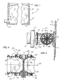
- FIGURE 1 is a schematic view of a container with a valve assembly for effecting either mass containment within or at-will distribution of product from the container.
- FIGURE 2 is an enlarged side elevational view, partially in section, illustrating one form of a valve assembly embodying features of the present invention.
- FIGURE 3 is an exploded perspective view of the valve assembly illustrated in FIGURE 2.
- FIGURE 4 is a sectional view taken along line 4 - 4 of FIGURE 2.
- FIGURE 5 is a longitudinal sectional view of the valve assembly showing a valve element conditioned to an open position.
- FIGURE 6 is an enlarged fragmentary cross-sectional view of a portion of the valve assembly of the present invention.
- FIGURE 7 is an enlarged sectional view of the area encircled in FIGURE 4.
- FIGURE 8 is another enlarged fragmentary side elevational view of the valve assembly.
- FIGURE 9 is a fragmentary sectional view taken along line 9 - 9 of FIGURE 8.
- FIGURE 10 is a longitudinal sectional view of an alternative form of the valve assembly of the present invention.
- FIGURE 11 is an enlargement of the area encircled in FIGURE 10.
- FIGURE 1 one form of a bulk container, generally indicated by reference numeral 10, for holding and shipping various semi-liquid or liquid products or substances.
- the bulk container 10 generally includes a load supporting outer container 12 with a series of interconnected, and preferably paperboard, walls 14 and a foil or film bladder or inner container 16.
- the inner container 16 is typically comprised of a synthetic resin or plastic material which is inert with respect to the product filled into the bag 16.
- the bladder or bag 16 is located within the outer container 12 and is shaped and dimensioned such that, upon filling with a product, the bag 16 generally conforms to the inner contours of the outer container walls 14.
- a valve assembly schematically indicated by reference numeral 20, is provided in operable combination with the inner bag 16 and extends through an opening 18 defined by one of the walls 14 on the outer container 12.
- the valve assembly 20 is described and illustrated for use with the bulk container 10, the valve assembly 20 is capable of use in other applications, which may include aseptic or non-aseptic applications.
- valve assembly 20 includes a valve body or housing 22 and a valve element or actuator 24 mounted for rotation between closed and open positions within the valve body or housing 22.
- the components 22, 24 of the valve assembly 20 can be fabricated from any number of different materials suitable for a particular application. That is, the components 22, 24 of the valve assembly 20 can be fabricated from a material selected from metal, non-metal, plastic, or other composite materials capable of withstanding the associated environment.
- the valve body 22 includes an upstream or inlet end 30 and an axially aligned downstream or outlet end 32.
- the upstream end 30 of the valve body 22 is adapted to open to an interior of the inner container 16.
- the upstream end 30 of the valve body 22 is configured to facilitate attachment of the valve body 22 to the inner container 16.
- the upstream end 30 of the valve body 22 may be ultrasonically sealed or otherwise operably secured to the inner container 16.
- the downstream end 32 of the valve body 22 is axially spaced from the upstream end 30 a sufficient distance whereby allowing the valve body 22 to extend through and beyond the exterior wall or surface of the outer container 12.
- the valve body downstream end 32 is configured with a generally circular flange 34, thereby enhancing the ability to releasably secure a pipe or hose 35 having a clamp 37 to the valve assembly 20 in a conventional manner.
- the flange 34 is not required as an attachment mechanism for an associated device.
- the valve assembly of the present invention could be used as an in-line valve, such as an in-line IV-valve, for use in the medical field. In such in-line applications, the flange 34 may or may not be necessary.
- valve body 22 is provided with a bore or passage 36 which opens to both the upstream and downstream ends 30 and 32, respectively, and through which product flows.
- the bore or passage 36 defines an elongated first axis 38.
- the throughbore or passage 36 has a generally circular cross-sectional configuration between the opposed ends 30, 32 and a diameter D (see also FIGURE 4) extending between two diametrically positioned points on a marginal edge 40. It should be appreciated, however, that the bore or passage 36 can have other cross-sectional configurations than that exemplified without detracting or departing from the spirit and scope of the present invention.
- valve body 22 is furthermore provided with a second bore 46 between the upstream and downstream ends 30 and 32, respectively, of the valve body 22 and defining a second axis 48 extending generally across and preferably normal or perpendicular to the first axis 38.
- axes 38 and 48 defined by passage 36 and bore 46, respectively are arranged in generally coplanar relation relative to each other.
- the second bore or opening 46 defines a generally cylindrical-like inner surface 47 within the valve body 22.
- the diameter of bore 46, within which the valve element 24 rotates is sized to be equal to or greater than a distance measured between any two diametrically opposed locations defined on the marginal edge 40 of passage 36 in a plane intersecting with axis 38 and extending generally parallel to axis 48 within that portion of the passage 36 that is in communication with the upstream end 30.
- the valve element 24 is sized and configured to cooperate with the inner surface 47 of the valve body 22 so as to close the passage 36.
- valve body 22 defines a pair of cylindrical seats 50 and 52 axially aligned relative to each other and which open to opposed sides of the valve body 22.
- Valve element 24 is mounted within bore 46 for rotation about fixed axis 48.
- valve element 24 includes a pair of radial flanges or trunnions 54 and 56 disposed toward opposed ends of and which combine with the cylindrical seats 50, 52 on the valve body 22 to support valve element or actuator 24 for rotation about fixed axis 48.
- the radial flanges 54, 56 are rigidly joined to each other by a solid web 58 having an outer dimension substantially equal to the diameter of the cylindrical-like inner surface 47 within the valve body 22 and the outer diameter of the radial flanges 54, 56.
- a closed position FIG. 4
- the radial flanges 54, 56 and web 58 of valve element 24 combine with the inner surface 47 of the valve body 22 to obstruct product flow and allow, if desired, for sterilization of the dispersion zone of the valve assembly 20.
- valve assembly 20 is conditioned in an open position (FIGURE 5), however, the web 58 of valve element 24 is positioned to permit product flow from container 10 (FIGURE 1) through the passage 36 between the inlet and outlet ends 30 and 32, respectively.
- seal structure 60 (FIGURE 3) is preferably arranged in operable combination with the valve element 24.
- seal structure 60 includes an elongated, and preferably elastomeric, seal 62 extending longitudinally along each side or edge of the valve element web 58 and generally parallel to axis 48 in sealing engagement with the inner surface 47 of bore 46.
- an elongated channel or slot 64 is provided along each side or edge of the web 58. As shown, the channel 64 opens to the inner surface 47 defined by bore 46.
- Each seal 62 is fixedly seated or accommodated within a slot 64 and operably combines with the valve element web 58 to inhibit product passing between the inner surface 47 and the valve element 24 as long as the valve element 24 is in a closed condition.
- seal structure 60 furthermore includes an annular, and preferably elastomeric, seal 66 arranged in surrounding relation about each radial valve element flange 54, 56 (with only flange 54 being shown in FIGURE 7) in rotational sealing engagement with the inner surface 47 of bore 46.
- a channel or slot 68 is provided around each valve element flange 54, 56 and opens to a respective cylindrical seat 50, 52.
- Each seal 66 is accommodated within a slot 68 and operably combines with a respective valve element radial flange 54, 56 to inhibit product to pass outwardly between surface 47 and the respective flange 54, 56 of element 24 regardless of the position of the valve element 24.
- the elongated seals 62 on opposed sides of the web 58 along with the annular seals 66 can be formed as a one-piece seal structure.
- structure 60 can be integrated into valve element 24 through a well known and conventional overmolding process.
- valve element 24 is releasably maintained within the valve body 22 to facilitate sterilization and repair/reconstruction of the valve assembly 20.
- cylindrical seat 50 extends outwardly from a side of the valve body 22 and terminates in a substantially flat surface 70 extending generally normal to axis 48.
- cylindrical seat 52 likewise extends outwardly from an opposite side of the valve body 22 and terminates in a face 72.
- valve element 24 has a length greater than the distance between surfaces 70 and 72 on the valve body 22. As such, and as illustrated in FIGURES 4 and 7, valve element 24 extends outwardly and beyond the valve seat 50.
- valve element 24 has a generally constant diameter between opposed ends thereof, thus, allowing element 24 to slidably move endwise within the bore 46 of the valve body 22 during assembly and disassembly of valve assembly 20.
- structure 76 preferably includes an annular ring 78 which limits linear displacement of valve element 24 within the bore 46 of the valve body 22.
- an annular channel 80 is axially disposed outward from channel 68 and opens to the portion of radial flange 54 extending axially outward from seat 50 so as to accommodate or seat the annular ring 78 at least partially therewithin.
- the channel or slot 80 is positioned relative to the flat surface 70 of seat 50 such that ring 78 engages and presses against face 70 to allow for rotational movement of the valve element 24 between positions while restricting linear displacement of and, thus, positioning the valve element 24 in a first direction within bore 46 of the valve body 22.
- removal of the ring 78 from operable combination with the valve element 24 readily permits the valve element 24 to slide to the left, as shown in FIGURE 7, relative to the valve body 22 to allow for repair/replacement of the valve element 24.
- ring 78 can take any of numerous forms.
- ring 78 can take the form of a conventional elastomeric O'ring.
- ring 78 can be a metal snap ring partially accommodated within the channel 80 while extending radially therefrom to permit interengagement with surface 70 on the valve body 22.
- other forms of rings or other conventional devices would equally suffice to effect positive positioning of and, yet, allow for removal of the valve element 24 relative to the valve body 22.
- valve element 24 is preferably configured to operably combine with the valve body 22 in restricting endwise or linear movement and positioning of valve element 24 within the bore 46 (FIGURE 3) relative to the valve body 22 in a second direction opposed to the first direction.
- surface 72 of valve body 22 has a stepped configuration. That is, an arcuate extension 82 projects axially away from the remainder of valve body surface 72 whereby creating two shoulders or steps 84 and 86 which, in the illustrated embodiment, are disposed about 90 degrees apart from one another.
- valve element 24 is provided with a radial flange 88 having a diameter greater than the diameter of bore 46 and extending around about a 180 degree outer segment of element 24.
- flange 88 is positioned to move past the arcuate extension 82 until flange 88 abuts surface 72 thereby limiting movement of the valve element 24 to the left, as seen in FIGURE 9, whereby endwise positioning valve element 24 in the second direction relative to bore 46 and valve body 22.
- opposed sides of flange 88 define two shoulders or steps 94 and 96 which are disposed approximately 180 degrees from each other and which, when valve element 24 is turned between positions, rotate in the same general plane as the shoulders or steps 84, 86 on the extension 82 of valve body 22 are disposed.
- the steps 84, 86 on the valve body 22 operably combine with the steps 94, 96, respectively, on the valve element flange 88 and act as stops to limit rotational movement of valve element 24.
- the stops 84, 86 and 94, 96 are mnemonically positioned to indicate the condition or position of valve assembly 20.
- valve element 24 is exteriorly configured to facilitate manual rotation thereof between open and closed positions.
- an axial extension 98 protrudes from one end of valve element 24.
- Extension 98 is preferably aligned with axis 48 and is configured for releasable engagement by a suitable tool, such as a wrench or the like, to promote turning movement of element 24 between positions.
- a suitable tool such as a wrench or the like
- extension 98 can likewise be configured such that a removable handle can be readily and easily used to promote turning movement of element 24 between open and closed positions.
- FIGURE 10 Another form or embodiment of valve assembly embodying principals of the present invention is illustrated in FIGURE 10.
- This alternative form of valve assembly is designated generally by reference numeral 120.
- the elements of this alternative form of valve assembly that are identical or functionally analogous to those elements or components of the valve assembly 20 discussed above are designated by reference numerals identical to those used above with the exception this embodiment of valve assembly uses reference numerals in the one-hundred series.
- the upstream end 130 of valve body 122 of valve assembly 120 is configured to promote fixing an attachment plate or disc 131 thereto.
- the upstream end 130 of valve body 122 defines a flange 133 extending radially outwardly from the valve body 122.
- Flange 133 includes an annular inner ring 135 and an annular outer ring 137 spaced at different radial distances relative to axis 138 of the valve body 122 and which define an annular open channel or slot 139 therebetween.
- both rings 135 and 137 are capable of radial flexure but return to a predetermined set position after being flexibly moved.
- the attachment plate or disc 131 is sized to radially project outwardly beyond the limit of the valve body 122 thereby facilitating suitable attachment of the valve assembly 120 to container 10 (FIGURE 1).
- the attachment plate or disc 131 defines an opening 141 which aligns with passage 136 in the valve body 122.
- opening 141 is sized generally equal to the bore 136 in valve body 122.
- An upstanding or projecting annular inner ring 145 surrounds the opening 141 with an outer annular ring 147 being concentrically arranged relative to inner ring 145 to define an open annular channel or slot 149 therebetween.
- the radial width of the annular channel 149 on the disc 131 is generally equal to the radial width of the annular inner ring 135 on the valve body 122.
- the outer annular ring 147 on disc 131 has a radial width generally equal to the radial width of the annular channel or slot 139 on the valve body 122.
- Suitable interlocking instrumentalities are provided on the valve body 122 and the attachment plate or disc 131 whereby securing the parts together.
- One form of interlocking instrumentality for securing valve body 122 and disc 131 in interlocked relation is illustrated in FIGURE 11.
- an annular inner surface 151 of the outer annular ring 137 on the valve body flange 133 defines an annular notch or groove 155 which is sized and configured to accommodate an annular protrusion 157 extending radially outward from the outer annular ring 147 on disc 131.
- the valve assembly provides for either mass containment or at-will distribution of any number of different materials, substances, or products, such as, low density product mixtures while, if desired, maintaining a sterile environment in a dispersion zone of the valve assembly.
- One feature of the present invention relates to the ability to manufacture the valve assembly from any of several different materials.
- the valve assembly can be designed as a permanent fixture of a container subsequently filled with mass transported substances, and, depending upon the material from which the valve assembly is fabricated, allows the container to be disposed of rather than recycled, thus, significantly reducing transportation costs for such materials by reducing the labor intensive aspect associated with sterilization procedures for each container .
- valve assembly of the present invention is readily replaceable and reusable. Removal of the valve element or actuator from the valve assembly is readily affected as through structure 76. Moreover, structure 76 is readily accessible from an exterior of the valve assembly thereby reducing the time and effort required to service the valve assembly.
- a feature of the present invention relates to sizing the diameter of bore 46 to be equal to or greater than a distance measured between any two opposed locations defined on a marginal edge of the inlet end of passage 36.
- Such a valve assembly design offers several advantages to the present invention. First, such design allows the rotatable valve element to be designed with edges which seal relative to an inner surface of the valve body and extend generally parallel to the axis of valve element rotation. As such, an improved force distribution and no preload forces are provided along the sealing edges of the valve element as compared to butterfly valves, thus, yielding advantageous ergonomic operation of the valve assembly. Second, such design allows the valve element to impart a wiping action to the inner surface of the valve body as the valve element rotates between closed and open positions.
Landscapes
- Engineering & Computer Science (AREA)
- General Engineering & Computer Science (AREA)
- Mechanical Engineering (AREA)
- Taps Or Cocks (AREA)
- Lift Valve (AREA)
- Multiple-Way Valves (AREA)
- Sliding Valves (AREA)
Abstract
Description
As shown, the second bore or
Claims (22)
- A valve assembly, comprising:a valve body having a passage defining a first axis, and a bore defining a second axis arranged generally coplanar with and normal to the first axis, the bore having an inner surface defined by an inner periphery thereof; anda valve element mounted in the bore for rotation about the second axis between a closed position, wherein the valve element cooperates with the inner surface of the bore to obstruct movement of product through the passage, and an open position, wherein the valve element is positioned relative to the inner surface of the bore so as to permit product movement through the passage.
- A valve assembly according to claim 1, wherein a diameter of the bore is equal to or greater than a distance measured across any two diametrically opposed locations defined by a marginal edge of the passage.
- A valve assembly, comprising:a valve body having a passage defining a first axis, an inlet end, and an outlet end, and a bore defining a second axis disposed in crossing relation to the first axis and between the inlet end and the outlet end of the passage; anda valve element mounted in the bore for rotation about the second axis between a closed position, wherein the valve element cooperates with an inner surface of the bore to obstruct movement of product through the passage, and an open position, wherein the valve element permits product movement through the passage, wherein a diameter of the bore is substantially equal to or greater than a distance measured across that portion of the passage which the valve element is adapted to close.
- A valve assembly according to at least one of the preceding claims, wherein the valve element includes a seal structure extending lengthwise of and generally parallel to the axis of rotation of the valve element.
- A valve assembly, comprising:a valve body having a passage defining a first axis, and a bore defining a second axis disposed in crossing relation to the first axis, the bore having an inner surface defined by an inner periphery thereof; anda valve structure including a pair of radial flanges disposed at opposed ends with a solid web member extending therebetween, the radial flanges being configured to mount the valve structure within the bore for rotation about the second axis between a closed position, wherein the valve structure cooperates with the inner surface of the bore to obstruct movement of product through the passage, and an open position, wherein the valve structure is positioned relative to the inner surface of the bore so as to permit product movement through the passage.
- A valve assembly according to claim 5, wherein the web member is generally rectangular in shape.
- A valve assembly according to claim 5 or 6, wherein a diameter of the bore is substantially equal to or greater than a distance measured across that portion of the passage which the valve structure is adapted to close.
- A valve assembly according to at least one of claims 3 to 7, wherein the second axis is generally coplanar with and normal to the first axis.
- A valve assembly according to at least one of claims 5 to 7, wherein the valve structure includes a seal structure extending lengthwise of and generally parallel to the axis of rotation of the valve structure, such that when the valve structure is in the closed position, the valve structure and the bore create a straight line seal therebetween so that a force created between the seal structure and the bore along the seal line does not substantially increase or vary as the seal structure rotates between the open and closed positions, thereby enhancing ergonomic operation of the valve structure.
- A valve assembly according to claim 9, wherein the seal structure applies a wiping action to the cooperative inner surface of the bore as the valve structure moves between the open and closed positions.
- A valve assembly according to at least one of claims 5 to 10, wherein the valve structure includes a seal structure having a first seal portion extending lengthwise on one side of the web member and generally parallel to the axis of rotation of the valve structure, a second seal portion extending lengthwise on an opposite side of the web member and generally parallel to the axis of rotation of the valve structure, a third seal portion extending around one of the radial flanges, and a fourth seal portion extending around the other radial flange, thereby creating a seal between the valve structure and the bore to prevent movement of product therepast when the valve structure is in the closed position.
- A valve assembly, comprising:a valve body having a generally cylindrical passage defining a first axis, and a generally cylindrical bore defining a second axis arranged generally coplanar with and normal to the first axis;a valve structure including a pair of radial flanges disposed at opposite ends with a generally rectangular solid web member extending therebetween, the radial flanges being configured to mount the valve structure within the bore for rotation about the second axis between a closed position, wherein the valve structure cooperates with the bore to obstruct movement of product through the passage, and an open position, wherein the valve structure cooperates with the bore to permit product movement through the passage; andwherein a diameter of the bore is equal to or greater than a distance measured between any two diametrically opposed locations on a marginal edge of the passage.
- A valve assembly according to claim 12, wherein the valve structure includes a seal structure extending lengthwise of and generally parallel to the axis of rotation of the valve structure, such that when the valve structure is in the closed position, the valve structure and the bore create a straight line seal therebetween.
- A valve assembly for use with a product holding container, the valve assembly comprising:a valve body having a generally cylindrical passage defining a first axis, and a generally cylindrical bore defining a second axis arranged generally coplanar with and normal to the first axis;a valve structure including a pair of radial flanges disposed at opposite ends with a generally rectangular solid web member extending therebetween, and a seal structure extending lengthwise of and generally parallel to opposite sides of the web member, the radial flanges being configured to mount the valve structure within the bore for rotation about the second axis between a closed position, wherein the seal structure cooperates with the bore to obstruct movement of product through the passage, and an open position, wherein the valve structure cooperates with the bore to permit product movement through the passage; andwherein a diameter of the bore is equal to or greater than a distance measured between any two diametrically opposed locations on a marginal edge of the passage.
- A valve assembly according to claim 14, wherein the product holding container is a liquid container having an outer container in surrounding relation to an inner container, and wherein the valve body includes an outer flange member adapted to facilitate attachment of the valve body to the inner container.
- A valve assembly according to claim 14 or 15, wherein the seal structure has a first seal portion extending lengthwise on one side of the web member and generally parallel to the axis of rotation of the valve structure, a second seal portion extending lengthwise on an opposite side of the web member and generally parallel to the axis of rotation of the valve structure, a third seal portion extending around one of the radial flanges, and a fourth seal portion extending around the other radial flange, thereby creating a seal between the valve structure and the bore to prevent movement of product therepast when the valve structure is in the closed position.
- A valve assembly according to claim 11 or 16, wherein the web member and flanges each include an appropriate slot adapted to receive the respective seal portion.
- A valve assembly according to at least one of claims 11, 16, 17, wherein the seal structure is made of a single piece of material.
- . A valve assembly according to at least one of claims 11, 16 to 18, wherein the seal structure is an elastomeric seal.
- A valve assembly according to at least one of claims 14 to 19, wherein the valve body and the valve structure are each made of a nylon material.
- A valve assembly according to at least one of claims 14 to 20, further including stops for limiting movement of the valve structure between the open and closed positions.
- A valve assembly according to at least one of claims 14 to 21, further comprising a rotation assistance device positioned on one end of one of the flanges to allow the valve structure to be rotated between the open and closed positions.
Applications Claiming Priority (2)
| Application Number | Priority Date | Filing Date | Title |
|---|---|---|---|
| US1371 | 2001-10-25 | ||
| US10/001,371 US6854710B2 (en) | 2001-10-25 | 2001-10-25 | Valve assembly |
Publications (3)
| Publication Number | Publication Date |
|---|---|
| EP1306595A2 true EP1306595A2 (en) | 2003-05-02 |
| EP1306595A3 EP1306595A3 (en) | 2003-11-19 |
| EP1306595B1 EP1306595B1 (en) | 2005-12-28 |
Family
ID=21695704
Family Applications (1)
| Application Number | Title | Priority Date | Filing Date |
|---|---|---|---|
| EP02023139A Expired - Lifetime EP1306595B1 (en) | 2001-10-25 | 2002-10-15 | Valve assembly |
Country Status (9)
| Country | Link |
|---|---|
| US (1) | US6854710B2 (en) |
| EP (1) | EP1306595B1 (en) |
| AU (1) | AU2002301697B2 (en) |
| BR (1) | BR0204393B1 (en) |
| CA (1) | CA2409633C (en) |
| DE (1) | DE60208302T2 (en) |
| ES (1) | ES2254583T3 (en) |
| MX (1) | MXPA02010470A (en) |
| NZ (1) | NZ522222A (en) |
Cited By (1)
| Publication number | Priority date | Publication date | Assignee | Title |
|---|---|---|---|---|
| JP2021188720A (en) * | 2020-06-03 | 2021-12-13 | 株式会社Kvk | Seal member, valve device, and faucet |
Families Citing this family (8)
| Publication number | Priority date | Publication date | Assignee | Title |
|---|---|---|---|---|
| GB0120726D0 (en) * | 2001-08-25 | 2001-10-17 | Arena Ibc Ltd | Valve assembly for containers |
| US20090000119A1 (en) * | 2007-06-26 | 2009-01-01 | Honeywell International, Inc. | Valve assemblies having valve flowbodies and methods of manufacturing |
| CN102808989B (en) * | 2012-08-16 | 2015-10-28 | 上海鸿研物流技术有限公司 | For the valve opening and closing device in IBCS and container |
| US20150048118A1 (en) * | 2013-08-13 | 2015-02-19 | Edward A. English | Cooler with reservoir |
| US20180313187A1 (en) * | 2017-05-01 | 2018-11-01 | Schlumberger Technology Corporation | Single body choke line and kill line valves |
| CN108644402A (en) * | 2018-05-15 | 2018-10-12 | 深圳市优美环境治理有限公司 | The valve mechanism of the improved more spools of sealing performance |
| KR102679852B1 (en) * | 2019-12-26 | 2024-06-28 | 로레알 | Valve system for formula cartridges |
| DE102020133047A1 (en) * | 2020-12-10 | 2022-06-15 | Röchling Automotive Se & Co.Kg | Injection molded plastic valve assembly for a motor vehicle |
Family Cites Families (38)
| Publication number | Priority date | Publication date | Assignee | Title |
|---|---|---|---|---|
| US299734A (en) * | 1884-06-03 | Cut-off for valves | ||
| US714410A (en) * | 1902-03-03 | 1902-11-25 | Charles Howell Stainton | Valve. |
| US3078070A (en) * | 1959-01-12 | 1963-02-19 | Apv Co Ltd | Valve |
| US3108778A (en) * | 1961-01-16 | 1963-10-29 | Mueller Brass Co | Blade type valve |
| US3133723A (en) * | 1962-09-27 | 1964-05-19 | Walworth Co | Gas valves |
| US3373968A (en) | 1965-04-12 | 1968-03-19 | Scaramucci Domer | Between-flange ball valve with slidable seats |
| US3799499A (en) * | 1972-08-31 | 1974-03-26 | Flair Mfg Corp | Fluid flow isolation/regulation valve |
| US3938553A (en) | 1973-11-08 | 1976-02-17 | Robert Ortega | Valve construction |
| US4022258A (en) | 1975-10-28 | 1977-05-10 | American Hospital Supply Corporation | Ported closure and connector therefor |
| US4201208A (en) | 1977-11-30 | 1980-05-06 | Abbott Laboratories | Sterile connecting device |
| US4234011A (en) * | 1979-12-05 | 1980-11-18 | Rockwell International Corporation | Plug valve construction |
| US4339110A (en) * | 1980-01-28 | 1982-07-13 | Purex Corporation | Butterfly valve |
| US4322018A (en) | 1980-04-17 | 1982-03-30 | Rutter Christopher C | Fluid dispenser |
| US4516692A (en) | 1982-02-17 | 1985-05-14 | Williamette Industries, Inc. | Disposable container assembly for liquids or semi-liquids in bulk |
| US4538789A (en) * | 1983-05-02 | 1985-09-03 | Purex Pool Products, Inc. | Automatic and manual actuator |
| US4796788A (en) | 1987-08-26 | 1989-01-10 | Liqui-Box Corporation | Bag-in-box packaging and dispensing of substances which will not readily flow by gravity |
| EP0358053B1 (en) | 1988-09-08 | 1995-07-19 | Sotralentz S.A. | Container assembly for the transport and storage of liquid or powdery products |
| US4966310A (en) | 1988-12-01 | 1990-10-30 | Hawkins Gerald P | Collapsible storage container and method for storing matter |
| DE4000652C1 (en) | 1990-01-11 | 1991-07-18 | Sotralentz S.A., Drulingen, Bas-Rhin, Fr | |
| US5188144A (en) | 1991-08-29 | 1993-02-23 | Hoke Incorporated | Plug valve |
| FR2694362B1 (en) | 1992-07-29 | 1994-09-30 | Comap | Cylindrical ball valve. |
| US5433345A (en) * | 1992-10-28 | 1995-07-18 | Dai Nippon Printing Co., Ltd. | Bag-in-carton and pouring spout thereof |
| US5335820A (en) | 1993-02-26 | 1994-08-09 | Christianson Systems, Inc. | Container and dispenser system for flowable solids |
| US5377876A (en) | 1993-04-14 | 1995-01-03 | Smernoff; Ronald | Disposable container for pourable materials having an interlocking spout |
| US5375741A (en) | 1993-05-12 | 1994-12-27 | Encon, Inc. | Container for bulk material and its method of manufacture |
| US5385233A (en) | 1993-12-01 | 1995-01-31 | Cmi International, Inc. | Portable bulk storage container |
| FR2735553B1 (en) | 1995-06-15 | 1997-07-25 | Legris Sa | CYLINDRICAL ROTATING BALL VALVE |
| US5794818A (en) | 1995-11-09 | 1998-08-18 | Romeo-Rim, Inc. | Container for bulk materials |
| DE19600642C1 (en) | 1996-01-10 | 1997-04-24 | Sotralentz Sa | Cut-off component with large nominal width |
| DE29723204U1 (en) | 1996-03-21 | 1998-04-30 | Saxlund International GmbH, 29614 Soltau | Valve with swiveling visor |
| JP3840773B2 (en) * | 1997-12-24 | 2006-11-01 | 株式会社デンソー | Ventilation path switching device |
| US6050545A (en) | 1998-01-21 | 2000-04-18 | Stolzman; Michael D. | Bulk container valve |
| US6164888A (en) | 1998-05-04 | 2000-12-26 | Kocks; Leon B. | Self-lubricating cap nut |
| US6050455A (en) | 1998-06-29 | 2000-04-18 | Creative Edge Design Group, Ltd. | Caseless dispenser container |
| FI982109A0 (en) | 1998-09-30 | 1998-09-30 | Tasowheel Oy | Valve |
| US6123122A (en) | 1998-10-20 | 2000-09-26 | Abel Unlimited, Inc. | Hygenic bottle cap and liquid dispensing system |
| PT1018614E (en) | 1999-01-08 | 2005-01-31 | Genebre Sa | ROTARY SHUTTER VALVE |
| US6361051B1 (en) | 1999-11-08 | 2002-03-26 | Eaton Coporation | Face seal for barrel type water valve |
-
2001
- 2001-10-25 US US10/001,371 patent/US6854710B2/en not_active Expired - Fee Related
-
2002
- 2002-10-15 EP EP02023139A patent/EP1306595B1/en not_active Expired - Lifetime
- 2002-10-15 DE DE60208302T patent/DE60208302T2/en not_active Expired - Lifetime
- 2002-10-15 ES ES02023139T patent/ES2254583T3/en not_active Expired - Lifetime
- 2002-10-23 MX MXPA02010470A patent/MXPA02010470A/en active IP Right Grant
- 2002-10-23 AU AU2002301697A patent/AU2002301697B2/en not_active Ceased
- 2002-10-23 BR BRPI0204393-9A patent/BR0204393B1/en not_active IP Right Cessation
- 2002-10-24 NZ NZ522222A patent/NZ522222A/en not_active IP Right Cessation
- 2002-10-24 CA CA002409633A patent/CA2409633C/en not_active Expired - Fee Related
Non-Patent Citations (1)
| Title |
|---|
| None |
Cited By (1)
| Publication number | Priority date | Publication date | Assignee | Title |
|---|---|---|---|---|
| JP2021188720A (en) * | 2020-06-03 | 2021-12-13 | 株式会社Kvk | Seal member, valve device, and faucet |
Also Published As
| Publication number | Publication date |
|---|---|
| ES2254583T3 (en) | 2006-06-16 |
| MXPA02010470A (en) | 2004-12-13 |
| US6854710B2 (en) | 2005-02-15 |
| DE60208302D1 (en) | 2006-02-02 |
| EP1306595B1 (en) | 2005-12-28 |
| CA2409633A1 (en) | 2003-04-25 |
| DE60208302T2 (en) | 2006-06-29 |
| NZ522222A (en) | 2004-06-25 |
| EP1306595A3 (en) | 2003-11-19 |
| CA2409633C (en) | 2006-10-17 |
| US20030080309A1 (en) | 2003-05-01 |
| BR0204393A (en) | 2003-09-16 |
| AU2002301697B2 (en) | 2007-03-01 |
| BR0204393B1 (en) | 2011-04-05 |
Similar Documents
| Publication | Publication Date | Title |
|---|---|---|
| US6854710B2 (en) | Valve assembly | |
| ES2752127T3 (en) | Fluid transfer device | |
| US7534074B2 (en) | Flow path switchover device for particulate transport | |
| CA1314859C (en) | Positive fluid seal butterfly valve | |
| TW505533B (en) | Filter and valve apparatus | |
| US7487808B2 (en) | Coupling seal docking device comprising two of said coupling seals and container comprising at least one of said coupling seals | |
| US7621292B2 (en) | Lined valve | |
| AU2018203721B2 (en) | Drain valve with rotatable angled outlet | |
| US20100084049A1 (en) | Coupling lock and attachment module and docking device, each containing said coupling lock | |
| US20100326531A1 (en) | Combination flow control valve and reverse flow check valve | |
| US5388807A (en) | Modular butterfly valve | |
| CN112888884A (en) | Valve with a valve body | |
| US9945485B2 (en) | Seal assembly for a sterile environment | |
| US6484745B1 (en) | Fill valve assembly | |
| US11441718B2 (en) | Compensator arrangement for transport systems | |
| US9377111B2 (en) | Butterfly valve | |
| EP2189692B1 (en) | Dispensing valve | |
| US5620167A (en) | Modular butterfly valve for tablets, capsules and the like | |
| US4717120A (en) | Discharge valve for bulk containers | |
| US2479997A (en) | Valved tank | |
| US12398815B1 (en) | Sanitary pulse valve | |
| WO2001076963A1 (en) | Telescoping valve assembly and method for use thereof | |
| US11852246B2 (en) | Valve assembly and method of producing the same | |
| JP3009319B2 (en) | Ball valve | |
| AU632177B2 (en) | Dispensing valve |
Legal Events
| Date | Code | Title | Description |
|---|---|---|---|
| PUAI | Public reference made under article 153(3) epc to a published international application that has entered the european phase |
Free format text: ORIGINAL CODE: 0009012 |
|
| AK | Designated contracting states |
Designated state(s): AT BE BG CH CY CZ DE DK EE ES FI FR GB GR IE IT LI LU MC NL PT SE SK TR |
|
| AX | Request for extension of the european patent |
Extension state: AL LT LV MK RO SI |
|
| PUAL | Search report despatched |
Free format text: ORIGINAL CODE: 0009013 |
|
| AK | Designated contracting states |
Kind code of ref document: A3 Designated state(s): AT BE BG CH CY CZ DE DK EE ES FI FR GB GR IE IT LI LU MC NL PT SE SK TR |
|
| AX | Request for extension of the european patent |
Extension state: AL LT LV MK RO SI |
|
| 17P | Request for examination filed |
Effective date: 20040227 |
|
| 17Q | First examination report despatched |
Effective date: 20040331 |
|
| AKX | Designation fees paid |
Designated state(s): DE ES FR GB IT |
|
| GRAP | Despatch of communication of intention to grant a patent |
Free format text: ORIGINAL CODE: EPIDOSNIGR1 |
|
| GRAS | Grant fee paid |
Free format text: ORIGINAL CODE: EPIDOSNIGR3 |
|
| GRAA | (expected) grant |
Free format text: ORIGINAL CODE: 0009210 |
|
| AK | Designated contracting states |
Kind code of ref document: B1 Designated state(s): DE ES FR GB IT |
|
| PG25 | Lapsed in a contracting state [announced via postgrant information from national office to epo] |
Ref country code: IT Free format text: LAPSE BECAUSE OF FAILURE TO SUBMIT A TRANSLATION OF THE DESCRIPTION OR TO PAY THE FEE WITHIN THE PRESCRIBED TIME-LIMIT;WARNING: LAPSES OF ITALIAN PATENTS WITH EFFECTIVE DATE BEFORE 2007 MAY HAVE OCCURRED AT ANY TIME BEFORE 2007. THE CORRECT EFFECTIVE DATE MAY BE DIFFERENT FROM THE ONE RECORDED. Effective date: 20051228 |
|
| REG | Reference to a national code |
Ref country code: GB Ref legal event code: FG4D |
|
| REF | Corresponds to: |
Ref document number: 60208302 Country of ref document: DE Date of ref document: 20060202 Kind code of ref document: P |
|
| REG | Reference to a national code |
Ref country code: ES Ref legal event code: FG2A Ref document number: 2254583 Country of ref document: ES Kind code of ref document: T3 |
|
| ET | Fr: translation filed | ||
| PLBE | No opposition filed within time limit |
Free format text: ORIGINAL CODE: 0009261 |
|
| STAA | Information on the status of an ep patent application or granted ep patent |
Free format text: STATUS: NO OPPOSITION FILED WITHIN TIME LIMIT |
|
| 26N | No opposition filed |
Effective date: 20060929 |
|
| PGFP | Annual fee paid to national office [announced via postgrant information from national office to epo] |
Ref country code: GB Payment date: 20101025 Year of fee payment: 9 |
|
| PGFP | Annual fee paid to national office [announced via postgrant information from national office to epo] |
Ref country code: ES Payment date: 20111026 Year of fee payment: 10 Ref country code: FR Payment date: 20111028 Year of fee payment: 10 |
|
| GBPC | Gb: european patent ceased through non-payment of renewal fee |
Effective date: 20121015 |
|
| REG | Reference to a national code |
Ref country code: FR Ref legal event code: ST Effective date: 20130628 |
|
| PG25 | Lapsed in a contracting state [announced via postgrant information from national office to epo] |
Ref country code: GB Free format text: LAPSE BECAUSE OF NON-PAYMENT OF DUE FEES Effective date: 20121015 |
|
| PG25 | Lapsed in a contracting state [announced via postgrant information from national office to epo] |
Ref country code: FR Free format text: LAPSE BECAUSE OF NON-PAYMENT OF DUE FEES Effective date: 20121031 |
|
| REG | Reference to a national code |
Ref country code: ES Ref legal event code: FD2A Effective date: 20140527 |
|
| PG25 | Lapsed in a contracting state [announced via postgrant information from national office to epo] |
Ref country code: ES Free format text: LAPSE BECAUSE OF NON-PAYMENT OF DUE FEES Effective date: 20121016 |
|
| PGFP | Annual fee paid to national office [announced via postgrant information from national office to epo] |
Ref country code: DE Payment date: 20151028 Year of fee payment: 14 Ref country code: IT Payment date: 20151026 Year of fee payment: 14 |
|
| REG | Reference to a national code |
Ref country code: DE Ref legal event code: R119 Ref document number: 60208302 Country of ref document: DE |
|
| PG25 | Lapsed in a contracting state [announced via postgrant information from national office to epo] |
Ref country code: DE Free format text: LAPSE BECAUSE OF NON-PAYMENT OF DUE FEES Effective date: 20170503 |
|
| PG25 | Lapsed in a contracting state [announced via postgrant information from national office to epo] |
Ref country code: IT Free format text: LAPSE BECAUSE OF NON-PAYMENT OF DUE FEES Effective date: 20161015 |