US4022258A - Ported closure and connector therefor - Google Patents
Ported closure and connector therefor Download PDFInfo
- Publication number
- US4022258A US4022258A US05/626,201 US62620175A US4022258A US 4022258 A US4022258 A US 4022258A US 62620175 A US62620175 A US 62620175A US 4022258 A US4022258 A US 4022258A
- Authority
- US
- United States
- Prior art keywords
- spike
- closure
- sleeve
- rib
- connector
- Prior art date
- Legal status (The legal status is an assumption and is not a legal conclusion. Google has not performed a legal analysis and makes no representation as to the accuracy of the status listed.)
- Expired - Lifetime
Links
Images

Classifications
-
- A—HUMAN NECESSITIES
- A61—MEDICAL OR VETERINARY SCIENCE; HYGIENE
- A61M—DEVICES FOR INTRODUCING MEDIA INTO, OR ONTO, THE BODY; DEVICES FOR TRANSDUCING BODY MEDIA OR FOR TAKING MEDIA FROM THE BODY; DEVICES FOR PRODUCING OR ENDING SLEEP OR STUPOR
- A61M5/00—Devices for bringing media into the body in a subcutaneous, intra-vascular or intramuscular way; Accessories therefor, e.g. filling or cleaning devices, arm-rests
- A61M5/14—Infusion devices, e.g. infusing by gravity; Blood infusion; Accessories therefor
- A61M5/162—Needle sets, i.e. connections by puncture between reservoir and tube ; Connections between reservoir and tube
-
- B—PERFORMING OPERATIONS; TRANSPORTING
- B65—CONVEYING; PACKING; STORING; HANDLING THIN OR FILAMENTARY MATERIAL
- B65D—CONTAINERS FOR STORAGE OR TRANSPORT OF ARTICLES OR MATERIALS, e.g. BAGS, BARRELS, BOTTLES, BOXES, CANS, CARTONS, CRATES, DRUMS, JARS, TANKS, HOPPERS, FORWARDING CONTAINERS; ACCESSORIES, CLOSURES, OR FITTINGS THEREFOR; PACKAGING ELEMENTS; PACKAGES
- B65D47/00—Closures with filling and discharging, or with discharging, devices
- B65D47/04—Closures with discharging devices other than pumps
- B65D47/06—Closures with discharging devices other than pumps with pouring spouts or tubes; with discharge nozzles or passages
- B65D47/10—Closures with discharging devices other than pumps with pouring spouts or tubes; with discharge nozzles or passages having frangible closures
-
- A—HUMAN NECESSITIES
- A61—MEDICAL OR VETERINARY SCIENCE; HYGIENE
- A61M—DEVICES FOR INTRODUCING MEDIA INTO, OR ONTO, THE BODY; DEVICES FOR TRANSDUCING BODY MEDIA OR FOR TAKING MEDIA FROM THE BODY; DEVICES FOR PRODUCING OR ENDING SLEEP OR STUPOR
- A61M5/00—Devices for bringing media into the body in a subcutaneous, intra-vascular or intramuscular way; Accessories therefor, e.g. filling or cleaning devices, arm-rests
- A61M5/14—Infusion devices, e.g. infusing by gravity; Blood infusion; Accessories therefor
- A61M5/162—Needle sets, i.e. connections by puncture between reservoir and tube ; Connections between reservoir and tube
- A61M2005/1623—Details of air intake
Definitions
- Sterile irrigating fluids commonly consisting of distilled water, normal saline, or physiological solutions of sorbitol or glycine, are widely used for post-operative irrigation, for flushing wounds and body passages, cavities, and other areas undergoing surgical examination or operation.
- continuous or intermittent irrigation is commonly required during transurethral prostatic resections and for cystoscopic examinations.
- Surgical apparatus particularly suitable for irrigation in transurethral resections is disclosed in co-owned U.S. Pat. No. 3,677,248.
- irrigating fluids The manner of administration of such irrigating fluids depends on the type of examination or treatment involved and particularly on the quantities of fluid required. Relatively large quantities are frequently needed for flushing purposes and, in those cases, the surgeon or assistant may simply remove the closure and pour the fluid directly from the bottle.
- the instrument is attached to the flexible tubing of an administration set with the connector of that set being secured to the bottle in place of its original closure.
- Administration sets for irrigation fluids are available with different forms of bottle connectors but each form has some shortcomings in terms of cost, inconvenience of use, and/or possible risks of fluid contamination.
- one connector takes the form of a threaded cap to which the flexible tubing of the administration set is permanently secured. Substitution of that cap for the original threaded bottle cap obviously requires considerable manipulation and time.
- the connector comprises a plug which need only be inserted into the mouth of the bottle; however, such a procedure still requires prior removal of the bottle's original cap.
- One aspect of this invention therefore lies in providing a dual-purpose closure for an irrigation bottle and, specifically, a closure which constitutes the original closure of the bottle, which is to be left in place when the irrigating fluid is to be administered through an administration set, and which is to be removed only if circumstances require that fluid be poured from the bottle. While it is recognized that closures with piercable membranes are widely used for intravenous administration of blood and parenteral fluids, such closures are ordinarily secured against removal (see, for example, U.S. Pat. No 2,730,097) and would be clearly unsuitable for use in the administration of irrigation solutions for that reason alone and also because of their relatively expensive, ordinarily multiple-piece, construction.
- This invention is concerned with a relatively simple, inexpensive one-piece molded plastic closure which functions as the original closure for the bottle of surgical irrigation fluid and which is readily unthreaded from the bottle when fluid is to be poured from that bottle.
- the imperforate closure is left in place and the connector of the administration set is frictionally coupled to the closure with a hollow spike portion of the connector piercing a wall portion of the closure.
- the one-piece closure is formed of semi-rigid plastic and has a generally cylindrical side wall, an annular top wall, a tubular sleeve communicating with the central opening of the top wall, and a bottom wall closing the lower end of the sleeve.
- an annular rib which projects into the cavity of the sleeve and which provides a primary sealing zone for slidably and sealingly engaging the outer surface of a connector spike insertable into the sleeve to pierce the bottom wall of that sleeve and to place the interior of the irrigation bottle in flow communication with an administration set.
- the sleeve is downwardly tapered and has along its inside surface a secondary sealing zone spaced between the primary zone and the bottom wall of the sleeve.
- the bottom wall has a dome-shaped upper surface which facilitates proper positioning and cutting action of the piercing spike.
- the spike is provided with an angularly-beveled cutting edge terminating at its lower end in a peripherally-disposed tip, has a lower portion of smaller external diameter than the upper portion thereof, and includes a separate airway for the introduction of filtered air into the bottle as its contents are drained.
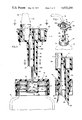
- FIG. 1 is a perspective view of a closure and connector embodying this invention.
- FIG. 2 is an enlarged vertical sectional view of the elements illustrated in FIG. 1, prior to coupling of the closure and connector.
- FIG. 3 is a fragmentary sectional view of the parts depicted in FIG. 2 but showing such parts just as the closure is pierced.
- FIG. 4 is a fragmentary sectional view similar to FIG. 3 but showing the connector fully inserted into the closure.
- FIG. 5 is a fragmentary sectional view taken along line 5--5 of FIG. 4.
- FIG. 6 is a fragmentary sectional view taken along line 6--6 of FIG. 4.
- FIG. 7 is a fragmentary plan view taken along line 7--7 of FIG. 2.
- FIG. 8 is a sectional view taken along line 8--8 of FIG. 2.
- FIG. 9 is a fragmentary sectional view taken along line 9--9 of FIG. 2.
- the numerals 10 and 11 generally designate the closure and connector, respectively, for the administration of surgical irrigation fluids.
- the closure 10 comprises a one-piece plastic cap having a cylindrical side wall 12, an annular top wall 13, a tubular sleeve 14 extending downwardly from the inside circumference of the top wall, and a bottom wall 15 closing the lower end of the sleeve. Since all of the walls are imperforate, the closure effectively seals the bottle 16 to which it is secured.
- the bottle itself is conventional, being formed from glass, plastic, or any other suitable material in accordance with teachings and practices known in the art, and a detailed description of the bottle is therefore believed unnecessary here. It is to be noted, however, that the bottle is provided with a threaded neck 16a received within the annular space between side wall 12 and sleeve 14, and that the side wall is internally threaded for detachable connection to the bottle neck.
- the closure is simply unthreaded from the neck in the usual manner.
- the tubular sleeve 14 is spaced a substantial distance inwardly, not only from the inside surface of side wall 12 but also from the inner surface of neck 16a to which the side wall is threadedly connected. Such spacing is important because it accommodates outward flexure or stretching of the sleeve's tubular wall during a coupling operation as will be described more fully hereinafter.
- the tubular sleeve is provided with an inwardly projecting annular rib 17 formed along its inner surface at a level adjacent to, but slightly below, the level of top wall 13. Below the rib, the inner surface 18 slopes or tapers gradually inwardly and downwardly so that the inside diameter of the sleeve at its lower end is less than the diameter of the opening defined by rib 17.
- the sleeve is provided with an upwardly and outwardly flared upper surface 20 which not only helps to guide a connecting spike into the sleeve but also results in a reduced thickness of material at 21 where the sleeve merges with the top wall. Such reduced thickness contributes in permitting outward stretching or flexure of the sleeve in its primary sealing zone when a spike is forced into the sleeve as described below. While the angle of upper surface 20 may vary, it has been found that particularly effective results are achieved if the surface slopes upwardly and outwardly (or downwardly and inwardly) at an angle within the range of 40° to 70° when measured from the horizontal, the preferred range being approximately 60°.
- Bottom wall 15 is dome-shaped in configuration and, in comparison with the other walls, is relatively thin, especially along its annular outer portion 15a which merges with the lower end of tubular sleeve 14. While the thickness of portion 15a may vary considerably depending upon the material used and the construction and composition of the piercing spike, it has been found that a minimum wall thickness of approximately 0.005 to 0.020 inches is effective if a high density polyethylene (having a density within the general range of 0.940 to 0.965 grams per cubic centimeter) is used. It is to be understood, of course, that other semi-rigid plastic materials having similar properties may be used in the fabrication of the closure.
- the selected material should be relatively stiff (i.e., should have a stiffness modulus of at least 50,000 psi when measured by ASTM test method D747-63T), so that a secure threaded connection will be formed between the side wall 12 and bottle neck 16a, and should have sufficient heat resistance to withstand autoclaving temperatures (250° F.).
- the dome shape of bottom wall 15 may be formed entirely in the molding operation, although it has been found that full development of the dome-shaped configuration may be obtained at least in part by increased pressure within bottle 16 when the sealed and filled bottle is subjected to sterilizing temperatures with cap 12 in place. Specifically, during such an autoclaving procedure, the thermoplastic material of the closure tends to soften, the bottom wall 15 assumes a fully-developed domed configuration as shown because of the increased internal pressure and also possibly because of limited shrinkage of the plastic, and upon cooling the plastic sets to retain the dome-shaped bottom wall configuration shown.
- the connector 11 consists essentially of a handle or body portion 22 and a spike 23.
- the spike has a tubular wall 24 terminating at its lower end in an angular cutting edge 25. While the spike is illustrated as having a single-bevel cutting edge, plural bevels may be provided as long as the cutting edge slopes generally upwardly from a peripherally-disposed tip portion 26 towards a diametrically-opposing heel portion 27.
- An enlarged recess 28 is formed in the heel, extending upwardly as shown in FIGS. 2, 5, and 8.
- a main passage 29 for the flow of irrigation fluid extends through the hollow spike and into the body portion, communicating with socket 30 which is in turn adapted to receive and retain the plug portion 31 of administration tube 32.
- the tube and its plug are entirely conventional and are therefore illustrated only in phantom. It is to be understood that the opposite end of the tube is adapted for connection to any of a variety of catheters, instruments, and other devices for the administration of irrigation fluids, and that if desired, the plug 31 may be eliminated and tube 32 may be joined directly to the connector 11.
- An airway 33 also extends through the hollow spike and, as shown most clearly in FIGS. 2 and 8, is separate from main passage 29.
- the airway extends to the tip portion 26 of the spike and, at its opposite end, communicates with a recess 34 in handle or body portion 22.
- a filter unit 35 containing a non-wetting microfilter of standard construction, is secured to the connector in flow communication with recess 34. The filter permits air, filtered for particulates and bacteria, to enter the bottle as its contents are drained without allowing liquid to escape through airway 33.
- the outside diameter of the upper portion 23a of the spike is substantially greater than the outside diameter of lower portion 23b.
- upper portion 23a has outside dimensions slightly greater than the opening defined by annular rib 17 in sleeve 14.
- the lower portion 23b has a smaller outside diameter than the inside diameter of the rib, the spike's minimum outside diameter being the same or slightly less than the minimum inside diameter of the sleeve at the lower end thereof.
- the length of the spike substantially exceeds the length of sleeve 14 and, specifically, that the length of reduced lower portion 23b (measured from heel 27 to the upper end of portion 23b) exceeds the distance between rib 17 and bottom wall 15.
- the length of the enlarged upper cylindrical portion 23a exceeds the distance between rib 17 (the primary sealing zone) and the secondary lower sealing zone 19.
- the body or handle portion of the spike preferably includes wing portions 22a which may be readily gripped to hold the connector between the fingers of one hand for driving the spike into fully seated position within the port sleeve of the closure.
- the body portion and spike of the connector are integrally formed of a rigid material.
- a rigid plastic such as polystyrene is preferred, although other plastic materials having similar properties of strength, rigidity, and hardness, or other materials such as metal, might be used.
- the rigidity or stiffness of the material of the connector 11 should be substantially greater than that of closure 10.
- any conventional protective cover (not shown) that may be provided over the entrance to the sleeve (to maintain the sterility of the surfaces thereof) is first removed and connector 11 of the administration set is then coupled to the closure by inserting spike 23 into the open-topped sleeve 14 in the manner illustrated in FIGS. 2-4.
- the reduced lower end portion 23b of the spike enters the sleeve and is freely slidable therein because of the greater internal dimensions of the sleeve.
- Tip 26 engages the periphery of bottom wall 15, piercing that wall and commencing the formation of an arcuate slit that extends about almost the entire periphery of that wall.
- the enlarged upper portion 23a of the spike slidably and sealingly engages the primary sealing zone defined by annular rib 17 (FIGS. 4-6). Since the outside diameter of the spike's upper portion 23a is greater than the inside diameter of the upper sealing zone, slight outward flexure or stretching of the sleeve occurs in the vicinity of the rib. As already indicated, such outward displacement of the rib portion is aided by reason of the fact that the rib is spaced below the level of top wall 13 (i.e., below the undersurface thereof) and because of the reduced wall thickness at 21.
- the enlarged portion 23a of the spike enters into engagement with the inside surface of the sleeve at the secondary sealing zone 19, causing further outward flexure or stretching of the sleeve at that location (FIGS. 4-6). Positive and highly effective sealing between the connector and closure is thereby achieved.
- the gripping forces exerted by the stretched sleeve upon the spike are sufficiently great to prevent extraction of the spike when the bottle is inverted for administration and even when pulling forces of considerable magnitude are exerted upon the flexible tube.
- the flared upper surface 20 will tend to realign or center the spike. Furthermore, should the spike be introduced at an angle, the cooperative action between the outer surface of lower spike portion 23b, and the lateral sliding action which tends to occur as tip 26 engages the domed top surface of wall 15, results in automatic realignment of the descending spike.
- closure 10 has been referred to as a "one-piece" closure to make it clear that the tubular port sleeve, which is piercable by and sealingly engagable with spike 23, is integral with top wall 13 and threaded side wall 12. It is to be understood, of course, that where the outer surface of the closure must be maintained in sterile condition, some outer cover (not shown) of any suitable or conventional design may be provided. Also, while the closure shown in the drawings is provided with a ribbed top wall 13 which sealingly engages the mouth of bottle 16, an annular resilient liner may if desired be interposed between the mouth and the underside of the top wall to contribute in forming an effective seal between the parts.
Abstract
Description
Claims (24)
Priority Applications (12)
| Application Number | Priority Date | Filing Date | Title |
|---|---|---|---|
| US05/626,201 US4022258A (en) | 1975-10-28 | 1975-10-28 | Ported closure and connector therefor |
| GB2361/76A GB1515616A (en) | 1975-10-28 | 1976-01-21 | Marker controlled telecommunication systems |
| DE19762647624 DE2647624A1 (en) | 1975-10-28 | 1976-10-21 | LOCK WITH HOLDER FOR A CONTAINER |
| CA263,881A CA1093019A (en) | 1975-10-28 | 1976-10-21 | Ported closure and connector therefor |
| CH1336876A CH610854A5 (en) | 1975-10-28 | 1976-10-22 | |
| GB44282/76A GB1536949A (en) | 1975-10-28 | 1976-10-25 | Containers and closures therefor |
| GB13215/78A GB1536950A (en) | 1975-10-28 | 1976-10-25 | Connectors for containers |
| PH19052A PH12879A (en) | 1975-10-28 | 1976-10-26 | Ported closure and connector therefor |
| JP51129997A JPS5254585A (en) | 1975-10-28 | 1976-10-27 | Cover for fluid vessel |
| AU19054/76A AU507719B2 (en) | 1975-10-18 | 1976-10-27 | Ported closure and connector therefor |
| AT0801176A AT371999B (en) | 1975-10-28 | 1976-10-28 | ONE-PIECE LOCKING CAP AND LOCKING ARRANGEMENT WITH SUCH A LOCKING CAP |
| CA344,074A CA1091626A (en) | 1975-10-28 | 1980-01-21 | Connector spike for ported closure |
Applications Claiming Priority (1)
| Application Number | Priority Date | Filing Date | Title |
|---|---|---|---|
| US05/626,201 US4022258A (en) | 1975-10-28 | 1975-10-28 | Ported closure and connector therefor |
Publications (1)
| Publication Number | Publication Date |
|---|---|
| US4022258A true US4022258A (en) | 1977-05-10 |
Family
ID=24509385
Family Applications (1)
| Application Number | Title | Priority Date | Filing Date |
|---|---|---|---|
| US05/626,201 Expired - Lifetime US4022258A (en) | 1975-10-18 | 1975-10-28 | Ported closure and connector therefor |
Country Status (9)
| Country | Link |
|---|---|
| US (1) | US4022258A (en) |
| JP (1) | JPS5254585A (en) |
| AT (1) | AT371999B (en) |
| AU (1) | AU507719B2 (en) |
| CA (1) | CA1093019A (en) |
| CH (1) | CH610854A5 (en) |
| DE (1) | DE2647624A1 (en) |
| GB (3) | GB1515616A (en) |
| PH (1) | PH12879A (en) |
Cited By (55)
| Publication number | Priority date | Publication date | Assignee | Title |
|---|---|---|---|---|
| US4177529A (en) * | 1978-08-18 | 1979-12-11 | Deere & Company | Filter wrench |
| EP0026055A1 (en) * | 1979-09-06 | 1981-04-01 | Diemoulders Proprietary Limited | Filling-dispensing neck and closure member combination for a bag-like container |
| US4325496A (en) * | 1980-08-22 | 1982-04-20 | Diemoulders Proprietary Limited | Filling-dispensing closure for a bag-like container |
| US4332333A (en) * | 1980-07-21 | 1982-06-01 | American Hospital Supply Corporation | Puncture spike handle |
| US4340147A (en) * | 1980-11-03 | 1982-07-20 | Mack-Wayne Plastics Company | Cap with built in piercing device |
| US4353488A (en) * | 1980-04-21 | 1982-10-12 | Container Technologies, Inc. | Flexible container with displaceable fitting and probe coupler apparatus |
| US4380310A (en) * | 1981-07-23 | 1983-04-19 | Container Technologies, Inc. | Flexible container with displaceable fitting and probe coupler apparatus |
| US4393909A (en) * | 1981-12-28 | 1983-07-19 | Baxter Travenol Laboratories, Inc. | Universal administration port |
| US4421253A (en) * | 1982-02-17 | 1983-12-20 | Willamette Industries, Inc. | Disposable container assembly for liquids or semi-liquids in bulk |
| EP0101613A2 (en) * | 1982-08-20 | 1984-02-29 | FranRica Mfg. Inc. | Aseptic flexible walled container |
| US4516692A (en) * | 1982-02-17 | 1985-05-14 | Williamette Industries, Inc. | Disposable container assembly for liquids or semi-liquids in bulk |
| US4681243A (en) * | 1984-03-07 | 1987-07-21 | Colpo Co., Ltd. | Cartridge with plug opening mechanism |
| US4699188A (en) * | 1986-01-17 | 1987-10-13 | Baker Henry E | Hygienic liquid dispensing system |
| US4834267A (en) * | 1987-11-02 | 1989-05-30 | Elkay Manufacturing Company | Bottled water cooler air filter |
| EP0379047A1 (en) * | 1989-01-19 | 1990-07-25 | Abbott Laboratories | Enteral delivery set assembly with internalized microbial filter |
| EP0380934A1 (en) * | 1989-01-17 | 1990-08-08 | Abbott Laboratories | Enteral delivery universal port assembly |
| US4949870A (en) * | 1986-07-02 | 1990-08-21 | Societe Generale Des Eaux Minerales De Vittel | Reinforced pouring assembly and its method of construction |
| US5232125A (en) * | 1991-10-08 | 1993-08-03 | Portola Packaging, Inc. | Non-spill bottle cap used with water dispensers |
| US5297599A (en) * | 1991-03-19 | 1994-03-29 | Hoffmann-Laroche Inc. | Closure device for sealing reagent containers in an automatic pipetting system |
| US5325995A (en) * | 1989-07-27 | 1994-07-05 | Du Pont Canada Inc. | Piercing nozzle for pouch fitment |
| US5584825A (en) * | 1994-12-01 | 1996-12-17 | Isolyser Co., Inc. | Closure delivery system |
| US5688046A (en) * | 1995-11-14 | 1997-11-18 | Eastman Kodak Company | Method and apparatus for mixing a container of concentrate with diluent from supply systems |
| US5687865A (en) * | 1991-10-08 | 1997-11-18 | Portola Packaging, Inc. | Spill-reduction cap for fluid container |
| US5697702A (en) * | 1995-11-14 | 1997-12-16 | Eastman Kodak Company | Batch mixer and reservoir lid for a mixing tank |
| US6000413A (en) * | 1998-09-01 | 1999-12-14 | Innova Electronics Corporation | Fuel injector cleaning system |
| US6032812A (en) * | 1996-07-22 | 2000-03-07 | Crealise Packaging Inc. | One-piece cap for liquid dispenser container |
| US6123122A (en) * | 1998-10-20 | 2000-09-26 | Abel Unlimited, Inc. | Hygenic bottle cap and liquid dispensing system |
| US6308849B1 (en) * | 1999-08-13 | 2001-10-30 | Charles Y. J. Kim | Cap for containers used on drinking water dispensers |
| US6408904B1 (en) | 1998-10-20 | 2002-06-25 | Abel Unlimited, Inc. | Hygienic bottle cap |
| US20030080309A1 (en) * | 2001-10-25 | 2003-05-01 | Anatoly Gosis | Valve assembly |
| US20040153047A1 (en) * | 2002-11-18 | 2004-08-05 | Ricardo Blank | Connector device |
| US20040217197A1 (en) * | 2003-04-18 | 2004-11-04 | Mazooji Amber N.D. | Automated cleansing sprayer having separate cleanser and air vent paths from bottle |
| US20050072489A1 (en) * | 2001-02-27 | 2005-04-07 | Kellogg Matthew Kenyon | Disposable/reusable lubrication container system |
| US6971549B2 (en) | 2003-04-18 | 2005-12-06 | S.C. Johnson & Son, Inc. | Bottle adapter for dispensing of cleanser from bottle used in an automated cleansing sprayer |
| US20060137763A1 (en) * | 2004-11-22 | 2006-06-29 | Brendan Hogan | Air vent foil cutter |
| USRE39340E1 (en) * | 1991-10-08 | 2006-10-17 | Portola Packaging, Inc. | Spill-reduction cap for fluid container |
| US20070163664A1 (en) * | 2004-06-17 | 2007-07-19 | Mijers Jan W M | Check valve |
| US20070163599A1 (en) * | 2004-06-07 | 2007-07-19 | Mijers Jan W | Apparatus for connecting a respiratory device with a patient |
| US20070278176A1 (en) * | 2006-06-06 | 2007-12-06 | Portola Packaging Inc. | Closure having a valve with an arcuate frangible line |
| US20070278175A1 (en) * | 2006-06-06 | 2007-12-06 | Portola Packaging, Inc. | Closure having inverted frangible valve |
| WO2008014605A1 (en) * | 2006-07-31 | 2008-02-07 | Liqui-Box Canada, Inc. | A piercing fitment assembly |
| US20080105713A1 (en) * | 2006-11-03 | 2008-05-08 | Fahy Cathal L | Device For Attaching A Dip Tube To A Fluid Container |
| US20100076397A1 (en) * | 2006-11-30 | 2010-03-25 | Jay Reed | Dual-lumen needle with an elongate notch opening |
| US20100122991A1 (en) * | 2008-11-17 | 2010-05-20 | The Coca-Cola Company | Sealable cap for spout |
| US20110118676A1 (en) * | 2009-05-11 | 2011-05-19 | Kropczynski Jr John J | Enteral Connectors and Systems |
| US8025173B2 (en) | 2006-09-07 | 2011-09-27 | Allegiance Corporation | Collapsible canister liner for medical fluid collection |
| US20120031923A1 (en) * | 2010-08-05 | 2012-02-09 | Ds Smith Plastics Limited | Closure valve assembly for a container |
| US20120283690A1 (en) * | 2008-02-08 | 2012-11-08 | Codan Us Corporation | Enteral feeding safety reservoir and system |
| US8460256B2 (en) | 2009-07-15 | 2013-06-11 | Allegiance Corporation | Collapsible fluid collection and disposal system and related methods |
| US8500706B2 (en) | 2007-03-23 | 2013-08-06 | Allegiance Corporation | Fluid collection and disposal system having interchangeable collection and other features and methods relating thereto |
| CN104667378A (en) * | 2015-03-13 | 2015-06-03 | 刘锦祥 | Disposable antivirus infusion device |
| US9080681B2 (en) | 2010-12-17 | 2015-07-14 | Weibel Cds Ag | Device for withdrawing liquid from a container |
| US9889239B2 (en) | 2007-03-23 | 2018-02-13 | Allegiance Corporation | Fluid collection and disposal system and related methods |
| CN108135775A (en) * | 2015-10-09 | 2018-06-08 | 费森尤斯卡比德国有限公司 | For accommodating the lid of the container of intestinal nutrient solution |
| CN111183099A (en) * | 2017-11-16 | 2020-05-19 | 百利盖控股有限公司 | Plastic closure member with breakable diaphragm |
Families Citing this family (6)
| Publication number | Priority date | Publication date | Assignee | Title |
|---|---|---|---|---|
| US4216885A (en) * | 1978-10-20 | 1980-08-12 | The Coca-Cola Company | Disposable package for dispensing liquids with a controlled rate of flow |
| USRE33338E (en) * | 1981-10-15 | 1990-09-18 | The Coca-Cola Company | Membrane seal and knife combination for a post-mix beverage dispensing system |
| SE437348B (en) * | 1983-07-29 | 1985-02-25 | Pharmacia Ab | CLOSING DEVICE FOR THE FLUID DUMP CONNECTION OF AN OPENING OF A FLUIDUM CONTAINER OR FLUIDUM PIPE |
| JP2923302B2 (en) * | 1989-05-17 | 1999-07-26 | テルモ株式会社 | Tubular body with diaphragm |
| JP4025961B2 (en) * | 2000-08-24 | 2007-12-26 | 日本軽金属株式会社 | Anaerobic opener for beverage containers |
| US7981101B2 (en) * | 2005-12-30 | 2011-07-19 | Carefusion 303, Inc. | Medical vial adapter with reduced diameter cannula and enlarged vent lumen |
Citations (4)
| Publication number | Priority date | Publication date | Assignee | Title |
|---|---|---|---|---|
| US3156369A (en) * | 1962-09-19 | 1964-11-10 | Ethicon Inc | Bicameral container |
| US3580423A (en) * | 1969-02-27 | 1971-05-25 | Realistic Co | Container closure and apparatus for opening same |
| US3831814A (en) * | 1969-07-25 | 1974-08-27 | Cutter Lab | Trocar-cannula |
| US3938520A (en) * | 1974-06-10 | 1976-02-17 | Abbott Laboratories | Transfer unit having a dual channel transfer member |
-
1975
- 1975-10-28 US US05/626,201 patent/US4022258A/en not_active Expired - Lifetime
-
1976
- 1976-01-21 GB GB2361/76A patent/GB1515616A/en not_active Expired
- 1976-10-21 CA CA263,881A patent/CA1093019A/en not_active Expired
- 1976-10-21 DE DE19762647624 patent/DE2647624A1/en not_active Withdrawn
- 1976-10-22 CH CH1336876A patent/CH610854A5/xx not_active IP Right Cessation
- 1976-10-25 GB GB44282/76A patent/GB1536949A/en not_active Expired
- 1976-10-25 GB GB13215/78A patent/GB1536950A/en not_active Expired
- 1976-10-26 PH PH19052A patent/PH12879A/en unknown
- 1976-10-27 JP JP51129997A patent/JPS5254585A/en active Pending
- 1976-10-27 AU AU19054/76A patent/AU507719B2/en not_active Ceased
- 1976-10-28 AT AT0801176A patent/AT371999B/en not_active IP Right Cessation
Patent Citations (4)
| Publication number | Priority date | Publication date | Assignee | Title |
|---|---|---|---|---|
| US3156369A (en) * | 1962-09-19 | 1964-11-10 | Ethicon Inc | Bicameral container |
| US3580423A (en) * | 1969-02-27 | 1971-05-25 | Realistic Co | Container closure and apparatus for opening same |
| US3831814A (en) * | 1969-07-25 | 1974-08-27 | Cutter Lab | Trocar-cannula |
| US3938520A (en) * | 1974-06-10 | 1976-02-17 | Abbott Laboratories | Transfer unit having a dual channel transfer member |
Cited By (87)
| Publication number | Priority date | Publication date | Assignee | Title |
|---|---|---|---|---|
| US4177529A (en) * | 1978-08-18 | 1979-12-11 | Deere & Company | Filter wrench |
| FR2433393A1 (en) * | 1978-08-18 | 1980-03-14 | Deere & Co | SOCKET WRENCH FOR FILTER |
| EP0026055A1 (en) * | 1979-09-06 | 1981-04-01 | Diemoulders Proprietary Limited | Filling-dispensing neck and closure member combination for a bag-like container |
| US4353488A (en) * | 1980-04-21 | 1982-10-12 | Container Technologies, Inc. | Flexible container with displaceable fitting and probe coupler apparatus |
| US4332333A (en) * | 1980-07-21 | 1982-06-01 | American Hospital Supply Corporation | Puncture spike handle |
| US4325496A (en) * | 1980-08-22 | 1982-04-20 | Diemoulders Proprietary Limited | Filling-dispensing closure for a bag-like container |
| US4340147A (en) * | 1980-11-03 | 1982-07-20 | Mack-Wayne Plastics Company | Cap with built in piercing device |
| US4380310A (en) * | 1981-07-23 | 1983-04-19 | Container Technologies, Inc. | Flexible container with displaceable fitting and probe coupler apparatus |
| US4393909A (en) * | 1981-12-28 | 1983-07-19 | Baxter Travenol Laboratories, Inc. | Universal administration port |
| US4421253A (en) * | 1982-02-17 | 1983-12-20 | Willamette Industries, Inc. | Disposable container assembly for liquids or semi-liquids in bulk |
| US4516692A (en) * | 1982-02-17 | 1985-05-14 | Williamette Industries, Inc. | Disposable container assembly for liquids or semi-liquids in bulk |
| EP0101613A2 (en) * | 1982-08-20 | 1984-02-29 | FranRica Mfg. Inc. | Aseptic flexible walled container |
| US4445550A (en) * | 1982-08-20 | 1984-05-01 | Franrica Mfg. Inc. | Flexible walled container having membrane fitment for use with aseptic filling apparatus |
| EP0101613A3 (en) * | 1982-08-20 | 1985-05-15 | FranRica Mfg. Inc. | Aseptic flexible walled container |
| US4681243A (en) * | 1984-03-07 | 1987-07-21 | Colpo Co., Ltd. | Cartridge with plug opening mechanism |
| US4699188A (en) * | 1986-01-17 | 1987-10-13 | Baker Henry E | Hygienic liquid dispensing system |
| US4949870A (en) * | 1986-07-02 | 1990-08-21 | Societe Generale Des Eaux Minerales De Vittel | Reinforced pouring assembly and its method of construction |
| US4834267A (en) * | 1987-11-02 | 1989-05-30 | Elkay Manufacturing Company | Bottled water cooler air filter |
| EP0380934A1 (en) * | 1989-01-17 | 1990-08-08 | Abbott Laboratories | Enteral delivery universal port assembly |
| EP0379047A1 (en) * | 1989-01-19 | 1990-07-25 | Abbott Laboratories | Enteral delivery set assembly with internalized microbial filter |
| US5325995A (en) * | 1989-07-27 | 1994-07-05 | Du Pont Canada Inc. | Piercing nozzle for pouch fitment |
| US5297599A (en) * | 1991-03-19 | 1994-03-29 | Hoffmann-Laroche Inc. | Closure device for sealing reagent containers in an automatic pipetting system |
| US5687865A (en) * | 1991-10-08 | 1997-11-18 | Portola Packaging, Inc. | Spill-reduction cap for fluid container |
| US5232125A (en) * | 1991-10-08 | 1993-08-03 | Portola Packaging, Inc. | Non-spill bottle cap used with water dispensers |
| USRE39340E1 (en) * | 1991-10-08 | 2006-10-17 | Portola Packaging, Inc. | Spill-reduction cap for fluid container |
| US5584825A (en) * | 1994-12-01 | 1996-12-17 | Isolyser Co., Inc. | Closure delivery system |
| US5672162A (en) * | 1994-12-01 | 1997-09-30 | Isolyser Co., Inc. | Closure delivery system |
| US5688046A (en) * | 1995-11-14 | 1997-11-18 | Eastman Kodak Company | Method and apparatus for mixing a container of concentrate with diluent from supply systems |
| US5697702A (en) * | 1995-11-14 | 1997-12-16 | Eastman Kodak Company | Batch mixer and reservoir lid for a mixing tank |
| US6032812A (en) * | 1996-07-22 | 2000-03-07 | Crealise Packaging Inc. | One-piece cap for liquid dispenser container |
| US6000413A (en) * | 1998-09-01 | 1999-12-14 | Innova Electronics Corporation | Fuel injector cleaning system |
| US6123122A (en) * | 1998-10-20 | 2000-09-26 | Abel Unlimited, Inc. | Hygenic bottle cap and liquid dispensing system |
| US6408904B1 (en) | 1998-10-20 | 2002-06-25 | Abel Unlimited, Inc. | Hygienic bottle cap |
| US6308849B1 (en) * | 1999-08-13 | 2001-10-30 | Charles Y. J. Kim | Cap for containers used on drinking water dispensers |
| US20070000572A1 (en) * | 2001-02-27 | 2007-01-04 | Kellogg Matthew K | Disposable/reusable lubrication container system |
| US20050072489A1 (en) * | 2001-02-27 | 2005-04-07 | Kellogg Matthew Kenyon | Disposable/reusable lubrication container system |
| US20030080309A1 (en) * | 2001-10-25 | 2003-05-01 | Anatoly Gosis | Valve assembly |
| US6854710B2 (en) | 2001-10-25 | 2005-02-15 | Illinois Tool Works Inc. | Valve assembly |
| US8100879B2 (en) | 2002-11-18 | 2012-01-24 | Nestec S.A. | Connector device for enteral administration set |
| US20040153047A1 (en) * | 2002-11-18 | 2004-08-05 | Ricardo Blank | Connector device |
| US7308990B2 (en) | 2003-04-18 | 2007-12-18 | S.C. Johnson & Son, Inc. | Automated cleansing sprayer having separate cleanser and air vent paths from bottle |
| US20060157500A1 (en) * | 2003-04-18 | 2006-07-20 | Mazooji Amber N | Automated cleansing sprayer having separate cleanser and air vent paths from bottle |
| US20040217197A1 (en) * | 2003-04-18 | 2004-11-04 | Mazooji Amber N.D. | Automated cleansing sprayer having separate cleanser and air vent paths from bottle |
| US6971549B2 (en) | 2003-04-18 | 2005-12-06 | S.C. Johnson & Son, Inc. | Bottle adapter for dispensing of cleanser from bottle used in an automated cleansing sprayer |
| US20080048050A1 (en) * | 2003-04-18 | 2008-02-28 | Mazooji Amber N D | Automated Cleansing Sprayer Having Separate Cleanser And Air Vent Paths From Bottle |
| US7021494B2 (en) | 2003-04-18 | 2006-04-04 | S. C. Johnson & Son, Inc. | Automated cleansing sprayer having separate cleanser and air vent paths from bottle |
| US7635097B2 (en) * | 2003-04-18 | 2009-12-22 | S.C. Johnson & Son, Inc. | Automated cleansing sprayer having separate cleanser and air vent paths from bottle |
| US20070163599A1 (en) * | 2004-06-07 | 2007-07-19 | Mijers Jan W | Apparatus for connecting a respiratory device with a patient |
| US7717116B2 (en) | 2004-06-07 | 2010-05-18 | Filtertek Inc. | Apparatus for connecting a respiratory device with a patient |
| USRE43886E1 (en) | 2004-06-07 | 2013-01-01 | Illinois Tool Works Inc. | Apparatus for connecting a respiratory device with a patient |
| US20070163664A1 (en) * | 2004-06-17 | 2007-07-19 | Mijers Jan W M | Check valve |
| US7673653B2 (en) | 2004-06-17 | 2010-03-09 | Filtertek Inc. | Check valve |
| US7516765B2 (en) | 2004-11-22 | 2009-04-14 | Filtertek Inc. | Air vent foil cutter |
| US20060137763A1 (en) * | 2004-11-22 | 2006-06-29 | Brendan Hogan | Air vent foil cutter |
| WO2007146484A3 (en) * | 2006-06-06 | 2008-11-20 | Portola Packaging Inc | Closure having inverted frangible valve |
| WO2007146484A2 (en) * | 2006-06-06 | 2007-12-21 | Portola Packaging, Inc. | Closure having inverted frangible valve |
| US20070278175A1 (en) * | 2006-06-06 | 2007-12-06 | Portola Packaging, Inc. | Closure having inverted frangible valve |
| US20070278176A1 (en) * | 2006-06-06 | 2007-12-06 | Portola Packaging Inc. | Closure having a valve with an arcuate frangible line |
| US20080029540A1 (en) * | 2006-07-31 | 2008-02-07 | Johnson James W | Piercing fitment assembly |
| US7980424B2 (en) * | 2006-07-31 | 2011-07-19 | Liqui-Box Corporation | Piercing fitment assembly |
| WO2008014605A1 (en) * | 2006-07-31 | 2008-02-07 | Liqui-Box Canada, Inc. | A piercing fitment assembly |
| US9770540B2 (en) | 2006-09-07 | 2017-09-26 | Allegiance Corporation | Collapsible canister liner for medical fluid collection |
| US8025173B2 (en) | 2006-09-07 | 2011-09-27 | Allegiance Corporation | Collapsible canister liner for medical fluid collection |
| US7938299B2 (en) * | 2006-11-03 | 2011-05-10 | S.C. Johnson & Son, Inc. | Device for attaching a dip tube to a fluid container |
| US20080105763A1 (en) * | 2006-11-03 | 2008-05-08 | Fahy Cathal L | Device for attaching a dip tube to a fluid container |
| US20080105713A1 (en) * | 2006-11-03 | 2008-05-08 | Fahy Cathal L | Device For Attaching A Dip Tube To A Fluid Container |
| US8403183B2 (en) | 2006-11-03 | 2013-03-26 | S. C. Johnson & Son, Inc. | Device for attaching a dip tube to a fluid container |
| US20100076397A1 (en) * | 2006-11-30 | 2010-03-25 | Jay Reed | Dual-lumen needle with an elongate notch opening |
| US9604778B2 (en) | 2007-03-23 | 2017-03-28 | Allegiance Corporation | Fluid collection and disposal system having interchangeable collection and other features and methods relating thereto |
| US9889239B2 (en) | 2007-03-23 | 2018-02-13 | Allegiance Corporation | Fluid collection and disposal system and related methods |
| US10252856B2 (en) | 2007-03-23 | 2019-04-09 | Allegiance Corporation | Fluid collection and disposal system having interchangeable collection and other features and methods relating thereof |
| US8500706B2 (en) | 2007-03-23 | 2013-08-06 | Allegiance Corporation | Fluid collection and disposal system having interchangeable collection and other features and methods relating thereto |
| US20120283690A1 (en) * | 2008-02-08 | 2012-11-08 | Codan Us Corporation | Enteral feeding safety reservoir and system |
| US20100122991A1 (en) * | 2008-11-17 | 2010-05-20 | The Coca-Cola Company | Sealable cap for spout |
| US20110118676A1 (en) * | 2009-05-11 | 2011-05-19 | Kropczynski Jr John J | Enteral Connectors and Systems |
| US8628509B2 (en) * | 2009-05-11 | 2014-01-14 | Abbott Laboratories | Enteral connectors and systems |
| US8460256B2 (en) | 2009-07-15 | 2013-06-11 | Allegiance Corporation | Collapsible fluid collection and disposal system and related methods |
| US8820591B2 (en) | 2010-08-05 | 2014-09-02 | Ds Smith Plastics Limited | Closure valve assembly for a container |
| US8973789B2 (en) | 2010-08-05 | 2015-03-10 | Ds Smith Plastics Limited | Closure valve assembly for a container |
| US20120031923A1 (en) * | 2010-08-05 | 2012-02-09 | Ds Smith Plastics Limited | Closure valve assembly for a container |
| US8397958B2 (en) * | 2010-08-05 | 2013-03-19 | Ds Smith Plastics Limited | Closure valve assembly for a container |
| US9080681B2 (en) | 2010-12-17 | 2015-07-14 | Weibel Cds Ag | Device for withdrawing liquid from a container |
| CN104667378A (en) * | 2015-03-13 | 2015-06-03 | 刘锦祥 | Disposable antivirus infusion device |
| CN108135775A (en) * | 2015-10-09 | 2018-06-08 | 费森尤斯卡比德国有限公司 | For accommodating the lid of the container of intestinal nutrient solution |
| US11045389B2 (en) * | 2015-10-09 | 2021-06-29 | Fresenius Kabi Deutschland Gmbh | Cover for a container for receiving an enteral nutrition solution |
| CN111183099A (en) * | 2017-11-16 | 2020-05-19 | 百利盖控股有限公司 | Plastic closure member with breakable diaphragm |
| US11377271B2 (en) | 2017-11-16 | 2022-07-05 | Bericap Holding Gmbh | Plastic closure part with severable membrane |
Also Published As
| Publication number | Publication date |
|---|---|
| GB1536949A (en) | 1978-12-29 |
| PH12879A (en) | 1979-09-25 |
| DE2647624A1 (en) | 1977-05-12 |
| CH610854A5 (en) | 1979-05-15 |
| GB1515616A (en) | 1978-06-28 |
| ATA801176A (en) | 1983-01-15 |
| JPS5254585A (en) | 1977-05-04 |
| CA1093019A (en) | 1981-01-06 |
| AU1905476A (en) | 1978-05-04 |
| AU507719B2 (en) | 1980-02-28 |
| AT371999B (en) | 1983-08-25 |
| GB1536950A (en) | 1978-12-29 |
Similar Documents
| Publication | Publication Date | Title |
|---|---|---|
| US4022258A (en) | Ported closure and connector therefor | |
| US3699964A (en) | Closed urinary drainage and irrigation system | |
| US5871476A (en) | Method and apparatus for removing and disposing of body fluids | |
| US3921630A (en) | Thermoplastic bottle with controlled lateral collapse and method of dispensing liquid therefrom | |
| US3509879A (en) | Parenteral liquid container having frangible part structure | |
| CA1130687A (en) | Disposable urethral catheter assembly | |
| US5207657A (en) | Recessed tip fluid dispenser | |
| US4925447A (en) | Aspirator without partition wall for collection of bodily fluids including improved safety and efficiency elements | |
| US4643309A (en) | Filled unit dose container | |
| US4681571A (en) | Suction canister with disposable liner and check valve | |
| US6494869B1 (en) | Method and apparatus for removing and disposing of body fluids | |
| US20060064065A1 (en) | Closed system irrigation connector for urinary catheters | |
| US4950247A (en) | Aspirator for collection of bodily fluids including improved safety and efficiency elements | |
| US4981473A (en) | Aspirator without partition wall for collection of bodily fluids including improved safety and efficiency elements | |
| US5002534A (en) | Aspirator without partition wall for collection of bodily fluids including improved safety and efficiency elements | |
| BRPI0817631B1 (en) | DEVICE FOR ADDING A MEDICATION TO AN INFUSION SOLUTION IN AN INFUSION CONTAINER | |
| US6361521B1 (en) | Nasal irrigation system | |
| US4775366A (en) | Aspirator for collection of bodily fluid | |
| US3230954A (en) | Venoclysis equipment and method of administering two different parenteral liquids therefrom | |
| US4799925A (en) | Aspirator for collection of bodily fluids | |
| JPS5820635B2 (en) | catheter adapter | |
| US4799924A (en) | Aspirator for collection of bodily fluids | |
| GB2058227A (en) | Bung assemblies for use with vacuum apparatus | |
| US4015605A (en) | Drainage receptacle | |
| US5122126A (en) | Nozzle member provided with sealing membrane |
Legal Events
| Date | Code | Title | Description |
|---|---|---|---|
| AS | Assignment |
Owner name: KENDALL MCGAW LABORATORIES, INC., 2525 MCGAW AVENU Free format text: ASSIGNMENT OF ASSIGNORS INTEREST. EFFECTIVE NOVEMBER 26, 1985.;ASSIGNOR:AMERICAN HOSPITAL SUPPLY CORPORATION, A CORP OF IL;REEL/FRAME:004600/0460 Effective date: 19851126 Owner name: KENDALL MCGAW LABORATORIES, INC., A CORP OF OH,CAL Free format text: ASSIGNMENT OF ASSIGNORS INTEREST;ASSIGNOR:AMERICAN HOSPITAL SUPPLY CORPORATION, A CORP OF IL;REEL/FRAME:004600/0460 Effective date: 19851126 |
|
| AS | Assignment |
Owner name: WELLS FARGO BANK, N.A. Free format text: SECURITY INTEREST;ASSIGNOR:MCGAW, INC., A CORP. OF OH;REEL/FRAME:005477/0809 Effective date: 19901022 |
|
| AS | Assignment |
Owner name: KENDALL MCGAW LABORATORIES, INC. AN OH CORPORAT Free format text: RELEASED BY SECURED PARTY;ASSIGNOR:MANUFACTURERS HANOVER TRUST COMPANY;REEL/FRAME:005709/0001 Effective date: 19901015 |
|
| AS | Assignment |
Owner name: KENDALL MCGAW LABORATORIES, INC., AN OH CORP. Free format text: RELEASED BY SECURED PARTY;ASSIGNOR:MANUFACTURERS HANOVER TRUST COMPANY;REEL/FRAME:005515/0206 Effective date: 19901015 |
|
| AS | Assignment |
Owner name: MCGAW, INC., MORAINE, MONTGOMERY COUNTY, A CORP. O Free format text: MERGER;ASSIGNOR:MG ACQUISITION CORP. A CORP. OF DE (MERGED TO) KENDALL MCGAW LABORATORIES, INC., A CORP. OF OHIO;REEL/FRAME:005640/0520 Effective date: 19910205 |
|
| STCF | Information on status: patent grant |
Free format text: PATENTED FILE - (OLD CASE ADDED FOR FILE TRACKING PURPOSES) |
|
| AS | Assignment |
Owner name: GENERAL ELECTRIC CAPITAL CORPORATION, A NEW YORK C Free format text: ASSIGNMENT OF ASSIGNORS INTEREST.;ASSIGNOR:MCGAW, INC., A DELAWARE CORP.;REEL/FRAME:006073/0600 Effective date: 19920401 |
|
| AS | Assignment |
Owner name: MCGAW, INC. A CORP. OF DELAWARE Free format text: SECURITY INTEREST;ASSIGNOR:WELLS FARGO BANK, N.A.;REEL/FRAME:006139/0057 Effective date: 19920401 |