EP1306578B1 - Verfahren zur Steuerung eines Aggregatelagers - Google Patents
Verfahren zur Steuerung eines Aggregatelagers Download PDFInfo
- Publication number
- EP1306578B1 EP1306578B1 EP20020019628 EP02019628A EP1306578B1 EP 1306578 B1 EP1306578 B1 EP 1306578B1 EP 20020019628 EP20020019628 EP 20020019628 EP 02019628 A EP02019628 A EP 02019628A EP 1306578 B1 EP1306578 B1 EP 1306578B1
- Authority
- EP
- European Patent Office
- Prior art keywords
- unit
- spring rate
- vibration
- max
- maximum
- Prior art date
- Legal status (The legal status is an assumption and is not a legal conclusion. Google has not performed a legal analysis and makes no representation as to the accuracy of the status listed.)
- Expired - Lifetime
Links
- 238000000034 method Methods 0.000 title claims description 31
- 230000001133 acceleration Effects 0.000 claims description 11
- 230000033001 locomotion Effects 0.000 claims description 9
- 230000007423 decrease Effects 0.000 claims description 4
- 230000001052 transient effect Effects 0.000 claims description 4
- 238000009413 insulation Methods 0.000 claims 1
- 230000010355 oscillation Effects 0.000 description 16
- 238000013016 damping Methods 0.000 description 4
- 238000001514 detection method Methods 0.000 description 4
- 238000004364 calculation method Methods 0.000 description 3
- 230000003247 decreasing effect Effects 0.000 description 3
- 238000005259 measurement Methods 0.000 description 3
- 230000005540 biological transmission Effects 0.000 description 2
- 238000002485 combustion reaction Methods 0.000 description 2
- 238000002955 isolation Methods 0.000 description 2
- 239000000969 carrier Substances 0.000 description 1
- 230000001419 dependent effect Effects 0.000 description 1
- 230000005284 excitation Effects 0.000 description 1
- 235000015095 lager Nutrition 0.000 description 1
- 238000005406 washing Methods 0.000 description 1
Images


Classifications
-
- F—MECHANICAL ENGINEERING; LIGHTING; HEATING; WEAPONS; BLASTING
- F16—ENGINEERING ELEMENTS AND UNITS; GENERAL MEASURES FOR PRODUCING AND MAINTAINING EFFECTIVE FUNCTIONING OF MACHINES OR INSTALLATIONS; THERMAL INSULATION IN GENERAL
- F16F—SPRINGS; SHOCK-ABSORBERS; MEANS FOR DAMPING VIBRATION
- F16F15/00—Suppression of vibrations in systems; Means or arrangements for avoiding or reducing out-of-balance forces, e.g. due to motion
- F16F15/02—Suppression of vibrations of non-rotating, e.g. reciprocating systems; Suppression of vibrations of rotating systems by use of members not moving with the rotating systems
-
- F—MECHANICAL ENGINEERING; LIGHTING; HEATING; WEAPONS; BLASTING
- F16—ENGINEERING ELEMENTS AND UNITS; GENERAL MEASURES FOR PRODUCING AND MAINTAINING EFFECTIVE FUNCTIONING OF MACHINES OR INSTALLATIONS; THERMAL INSULATION IN GENERAL
- F16F—SPRINGS; SHOCK-ABSORBERS; MEANS FOR DAMPING VIBRATION
- F16F13/00—Units comprising springs of the non-fluid type as well as vibration-dampers, shock-absorbers, or fluid springs
- F16F13/04—Units comprising springs of the non-fluid type as well as vibration-dampers, shock-absorbers, or fluid springs comprising both a plastics spring and a damper, e.g. a friction damper
- F16F13/26—Units comprising springs of the non-fluid type as well as vibration-dampers, shock-absorbers, or fluid springs comprising both a plastics spring and a damper, e.g. a friction damper characterised by adjusting or regulating devices responsive to exterior conditions
-
- F—MECHANICAL ENGINEERING; LIGHTING; HEATING; WEAPONS; BLASTING
- F16—ENGINEERING ELEMENTS AND UNITS; GENERAL MEASURES FOR PRODUCING AND MAINTAINING EFFECTIVE FUNCTIONING OF MACHINES OR INSTALLATIONS; THERMAL INSULATION IN GENERAL
- F16F—SPRINGS; SHOCK-ABSORBERS; MEANS FOR DAMPING VIBRATION
- F16F7/00—Vibration-dampers; Shock-absorbers
- F16F7/10—Vibration-dampers; Shock-absorbers using inertia effect
- F16F7/1005—Vibration-dampers; Shock-absorbers using inertia effect characterised by active control of the mass
Definitions
- the invention relates to a method for controlling an assembly bearing according to the preamble of claim 1.
- the invention provides a method for controlling an assembly bearing, its spring rate primarily on the isolation of the generated by an aggregate Vibration is tuned. With a device for changing the spring rate becomes a transient low-frequency natural vibration of the unit prevented.
- the method is characterized in that the spring rate during a certain period of time, which is exactly one quarter of the oscillation period of the Natural vibration of the unit corresponds, is changed so that the bearing stiffness, within a maximum of ten milliseconds, from a basic stiffness with a certain spring rate steadily up to a maximum stiffness increases with a maximum spring rate and then steadily so falls off that the basic stiffness with the specific spring rate exactly after the determined Time duration is reached, wherein at least one measured variable, by means of which the movement the aggregate can be detected, in particular the acceleration of the aggregate, is constantly detected by at least one pickup.
- This method forms a closed loop for constantly determining the currently ideal rigidity of the assembly bearing during the low-frequency oscillation process, as a function of the oscillation speed.
- the occurrence of the so-called Stucker vibrations is detected from the tracking of the movement of the unit, for example by means of an accelerometer, on the exceeding of a predetermined limit value A G1 of vibration, vibration velocity or vibration acceleration.
- a very opportune moment at which the change in the spring rate for damping Stucker vibrations can begin is a zero crossing of the low-frequency natural oscillation, in particular if the change in the spring rate with respect to the low-frequency natural oscillation curve is repeated periodically or stochastically.
- the active change of the spring rate of the assembly bearings is deactivated if all low-frequency natural vibrations of the unit fall below a further specified limit value.
- the determination of the maximum vibration velocity for each half oscillation period or the single detection of the maximum vibration velocity is possible.
- the former is characterized in that the value of the current ideal spring rate c (t) of the assembly bearing is set equal to the value of the spring rate c 0 of the basic stiffness, if the quotient k v (t) from the current vibration velocity v aggregate (t) and the maximum Vibration velocity v aggregate max of the aggregate at the time of a zero crossing v maxr of the aggregate oscillation is negative. If the quotient k v (t) is positive at the moment of a zero crossing v maxr of the aggregate oscillation , the value of the actual ideal spring rate c (t) of the aggregate bearing is set to be greater than the value of the spring rate c 0 of the basic stiffness.
- the value of the current ideal spring rate c (t) of the assembly bearing then results from an addition of the spring rate c 0 of the basic stiffness and the spring rate c max of the maximum stiffness minus the spring rate c 0 of the basic stiffness multiplied by the value of the quotient k v (t) the current vibration velocity v aggregate (t) and the maximum vibration velocity v aggregate max of the aggregate at the moment of a zero crossing v maxr of the aggregate oscillation , if the value of the quotient of the current oscillation velocity v aggregate (t) and the maximum oscillation velocity v aggregate max of the aggregate for Time of zero crossing v maxr is positive or zero.
- the value of the actual ideal spring rate c (t) of the unit mount is set equal to the value of the spring rate c 0 of the basic stiffness when the magnitude of the quotient k v (t) is increasing over time , If the magnitude of the quotient k v (t) over the time is decreasing or constant and between zero and one, the value of the current ideal spring rate c (t) of the aggregate bearing results from an addition of the spring rate c 0 of the basic stiffness and the spring rate c max of the maximum stiffness, minus the spring rate c 0 of the basic stiffness multiplied by the amount of the quotient of the current vibration velocity v aggregate (t) and the maximum vibration velocity v aggregate max of the aggregate.
- a big advantage of the method is that the assembly bearing, if the Relative speed between a body and the unit damping acts, can be controlled so that with the decrease of the low-frequency Natural vibration of the aggregate the maximum stiffness with the maximum spring rate of the assembly bearing decreases and if the relative speed between the body and the aggregate fanning, on the assembly bearing the basic stiffness can be set with the specific spring rate.
- Claim 13 describes a preferred application of the invention.
- the aggregate storage is designed here as an engine mount in a motor vehicle and the Isolation of the free gas and mass forces of the engine, usually an internal combustion engine, designed accordingly soft.
- the motor also performs low frequency movements (stucco vibrations) with the natural frequency of engine mounting (about 5 to 15 Hz), for example due to roadway suggestions.
- Stucco vibrations low frequency movements
- the natural frequency of engine mounting about 5 to 15 Hz
- This principle is preferably applicable to assembly mountings of motor vehicles, but also for other storage situations with high requirements regarding Vibration comfort, smoothness and acoustics.
- Examples of this are storage systems for ships, rail vehicles, aircraft or stationary machinery or drives, for example compressors, washing machines, machine tools, Carriers etc. It serves to improve the acoustics and vibration comfort in all operating states of the units.
- FIG. 1 shows the mounting of a drive unit 1, which consists of a motor 3 and a transmission 4 composed.
- the drive unit 1 is via assembly storage 2 and 2 'mounted relative to a body 5.
- the body 5 is in turn about springs 6 and not shown dampers on not shown wheels supported.
- the assembly bearings 2, 2 ' have a variable spring rate.
- Figure 2 shows an aggregate 1, via a bearing 2, consisting of a damper 2 "and a spring 2 'with a over time t variable spring rate c to a Environment 3 is connected.
- the unit 1 may be due to the compliance of the bearing 2 in the direction of arrow A perform movements that are divided by a Let s represent s or a speed v or an acceleration a.
- the unit 1 for example, the internal combustion engine of a motor vehicle, oscillates periodically, as well as the environment 3, for example, the body of a motor vehicle which executes movements in the direction of the arrow K which are also by a path s or a speed v or an acceleration a let represent.
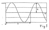
- FIG. 3 shows the course of an acceleration a of the unit 1 over time t shown.
- the acceleration a (t) of the unit 1 is constantly detected by measurement.
- K v (t) v aggregate (t) / v aggregate maxr
- K v (t) v aggregate (t) / v aggregate maxr or if v aggregate (t) / v Aggregate maxr ⁇ 0
- K v (t) 0
- c 0 basic or minimum spring rate
- C max maximum spring rate
- the current relative maximum speed is stored when exceeding the limit value A G1 .
- the ideal current spring rate c (t) is calculated according to the following algorithm: as long as
- / dt ⁇ 0, c (t) c 0 + c s ⁇
- / dt> 0, then c (t) c 0
- Characteristic of this procedure is that of the storage over the time occupied maximum spring stiffness decreases with decreasing vibration, which brings advantages in comfort.
Landscapes
- Engineering & Computer Science (AREA)
- General Engineering & Computer Science (AREA)
- Mechanical Engineering (AREA)
- Physics & Mathematics (AREA)
- Acoustics & Sound (AREA)
- Aviation & Aerospace Engineering (AREA)
- Vibration Prevention Devices (AREA)
- Support Of The Bearing (AREA)
Description
- Figur 1
- in schematischer Darstellung die Anordnung eines Antriebsaggregates in einem Kraftfahrzeug,
- Figur 2
- eine schematische Darstellung eines Aggregates, das mittels einer Feder mit veränderbarer Federrate gelagert ist,
- Figur 3
- den Schwingungsverlauf der Eigenschwingung des Aggregates von Figur 2 und
- Figur 4
- den Schwingungsverlauf der Eigenschwingung des Aggregates von Figur 2 in anderer Darstellung mit dem zeitlich daran gekoppelten Verlauf der Federrate des Lagers von Figur 2 bei einer Ansteuerung nach dem erfindungsgemäßen Verfahren.
c0 = Basis- bzw. minimale Federrate,
Cmax = maximale Federrate
cs = Spreizung der Federrate = cmax - c0
solange |kv(t)| über der Zeit fallend oder konstant ist, d.h. d|kv(t)|/dt ≤ 0, ist c(t) = c0 + cs · |kv(t)| mit der Bedingung 0 ≤ |kv(t)| ≤ 1,
wenn |kv(t)| über der Zeit anwächst, d.h. d|kv(t)|/dt > 0, dann ist c(t) = c0
Claims (13)
- Verfahren zur Steuerung eines Aggregatelagers (2,2'), dessen Federrate (c) vorrangig auf die Isolation der von einem Aggregat (1) erzeugten Schwingungen abgestimmt ist, mit einer Einrichtung zur Veränderung der Federrate (c) zur Verhinderung des Einschwingens einer niederfrequenten Eigenschwingung des Aggregats (1), dadurch gekennzeichnet, dass die Federrate (c) während einer bestimmten Zeitdauer, die genau einem Viertel (T/4) der Schwingungsdauer (T0) der Eigenschwingung des Aggregates (1) entspricht, so verändert wird, dass die Lagersteifigkeit, innerhalb von höchstens zehn Millisekunden, von einer Grundsteifigkeit mit einer bestimmten Federrate (c0) stetig bis zu einer Maximalsteifigkeit mit einer maximalen Federrate (cmax) ansteigt und anschließend stetig so abfällt, dass die Grundsteifigkeit mit der bestimmten Federrate (c0) genau nach der bestimmten Zeitdauer (T/4) erreicht wird, wobei mindestens eine Messgröße, mittels derer die Bewegung des Aggregats (1) erfasst werden kann, insbesondere die Beschleunigung (aAggregat) des Aggregats (1), durch mindestens einen Aufnehmer ständig erfasst wird.
- Verfahren nach Anspruch 1, dadurch gekennzeichnet, dass der Zeitpunkt, an dem die Veränderung der Federrate (c) beginnt, einem Nulldurchgang der niederfrequenten Eigenschwingung entspricht.
- Verfahren nach Anspruch 1 oder 2, dadurch gekennzeichnet, dass die Veränderung der Federrate (c) bezogen auf den niederfrequenten Eigenschwingungsverlauf periodisch oder stochastisch wiederholt wird.
- Verfahren nach einem der vorhergehenden Ansprüche, dadurch gekennzeichnet, dass dieses beim Auftreten von niederfrequenten Eigenschwingungen des Aggregates (1), von denen mindestens eine einen vorgegebenen Grenzwert überschreitet, aktiviert wird und deaktiviert wird, wenn alle niederfrequenten Eigenschwingungen des Aggregates (1) einen weiteren vorgegebenen Grenzwert unterschreiten.
- Verfahren nach einem der vorhergehenden Ansprüche, dadurch gekennzeichnet, dass während des niederfrequenten Schwingvorganges des Aggregats (1), in einem geschlossenen Regelkreis ständig die aktuelle ideale Federrate (c) des Aggregatelagers (2,2') in Abhängigkeit von der Schwinggeschwindigkeit (vAggregat) ermittelt wird, indem ständig eine Kenngröße gebildet wird, die dem Quotienten (kv(t)) aus der aktuellen Schwinggeschwindigkeit (vAggregat(t)) und der maximalen Schwinggeschwindigkeit (vAggregat max) des Aggregats (1) entspricht.
- Verfahren nach Anspruch 5, dadurch gekennzeichnet, dass die maximale Schwinggeschwindigkeit (vAggregat max) des Aggregats (1) für jede halbe Schwingungsperiode beim Auftreten von niederfrequenten Eigenschwingungen des Aggregates (1), von denen mindestens eine einen vorgegebenen Grenzwert überschreitet, ermittelt wird.
- Verfahren nach Anspruch 5, dadurch gekennzeichnet, dass die maximale Schwinggeschwindigkeit (vAggregat max) des Aggregats (1) nur einmal beim Auftreten von niederfrequenten Eigenschwingungen des Aggregates (1), von denen mindestens eine einen vorgegebenen Grenzwert überschreitet, ermittelt wird.
- Verfahren nach Anspruch 6, dadurch gekennzeichnet, dass der Wert der aktuellen idealen Federrate (c(t)) des Aggregatelagers (2,2') gleich dem Wert der Federrate (C0) der Grundsteifigkeit gesetzt wird, wenn der Quotient (kv(t)) aus der aktuellen Schwinggeschwindigkeit (vAggregat(t)) und der maximalen Schwinggeschwindigkeit (vAggregat max) des Aggregats (1) zum Zeitpunkt eines Nulldurchgangs (vmaxr) der Aggregateschwingung negativ ist.
- Verfahren nach Anspruch 6, dadurch gekennzeichnet, dass der Wert der aktuellen idealen Federrate (c(t)) des Aggregatelagers (2,2') größer dem Wert der Federrate (c0) der Grundsteifigkeit gesetzt wird, wenn der Quotient (kv(t)) aus der aktuellen Schwinggeschwindigkeit (vAggregat(t)) und der maximalen Schwinggeschwindigkeit (vAggregat max) des Aggregats (1) zum Zeitpunkt eines Nulldurchgangs (vmaxr) der Aggregateschwingung positiv ist.
- Verfahren nach Anspruch 9, dadurch gekennzeichnet, dass sich der Wert der aktuellen idealen Federrate (c(t)) des Aggregatelagers (2,2') ergibt aus einer Addition der Federrate (c0) der Grundsteifigkeit und der Federrate (cmax) der Maximalsteifigkeit abzüglich der Federrate (c0) der Grundsteifigkeit multipliziert mit dem Wert des Quotienten (kv(t)) aus der aktuellen Schwinggeschwindigkeit (vAggregat(t)) und der maximalen Schwinggeschwindigkeit (vAggregat max) des Aggregats (1) zum Zeitpunkt eines Nulldurchgangs (vmaxr) der Aggregateschwingung, wenn der Wert des Quotienten aus der aktuellen Schwinggeschwindigkeit (vAggregat(t)) und der maximalen Schwinggeschwindigkeit (vAggregat max) des Aggregats (1) zum Zeitpunkt eines Nulldurchgangs (vmaxr) positiv oder Null ist.
- Verfahren nach Anspruch 7, dadurch gekennzeichnet, dass der Wert der aktuellen idealen Federrate (c(t)) des Aggregatelagers (2,2') gleich dem Wert der Federrate (c0) der Grundsteifigkeit gesetzt wird, wenn der Betrag des Quotienten (kv(t)) aus der aktuellen Schwinggeschwindigkeit (vAggregat(t)) und der maximalen Schwinggeschwindigkeit (vAggregat max) des Aggregats (1) über der Zeit steigend ist.
- Verfahren nach Anspruch 7, dadurch gekennzeichnet, dass sich der Wert der aktuellen idealen Federrate (c(t)) des Aggregatelagers (2,2') ergibt aus einer Addition der Federrate (c0) der Grundsteifigkeit und der Federrate (cmax) der Maximalsteifigkeit abzüglich der Federrate (c0) der Grundsteifigkeit multipliziert mit dem Betrag des Quotienten aus der aktuellen Schwinggeschwindigkeit (vAggregat(t)) und der maximalen Schwinggeschwindigkeit (vAggregat max) des Aggregats (1), wenn der Betrag des Quotienten (kv(t)) über der Zeit fallend oder konstant ist und zwischen Null und Eins liegt.
- Verfahren nach einem der vorhergehenden Ansprüche zur Verhinderung des Einschwingens einer niederfrequenten Eigenschwingung (Stuckerschwingung) des Antriebsaggregates (1) eines Kraftfahrzeuges.
Applications Claiming Priority (2)
| Application Number | Priority Date | Filing Date | Title |
|---|---|---|---|
| DE10150607 | 2001-10-12 | ||
| DE2001150607 DE10150607A1 (de) | 2001-10-12 | 2001-10-12 | Verfahren zur Steuerung eines Aggregatelagers |
Publications (3)
| Publication Number | Publication Date |
|---|---|
| EP1306578A2 EP1306578A2 (de) | 2003-05-02 |
| EP1306578A3 EP1306578A3 (de) | 2004-07-21 |
| EP1306578B1 true EP1306578B1 (de) | 2005-12-07 |
Family
ID=7702412
Family Applications (1)
| Application Number | Title | Priority Date | Filing Date |
|---|---|---|---|
| EP20020019628 Expired - Lifetime EP1306578B1 (de) | 2001-10-12 | 2002-09-03 | Verfahren zur Steuerung eines Aggregatelagers |
Country Status (3)
| Country | Link |
|---|---|
| EP (1) | EP1306578B1 (de) |
| DE (2) | DE10150607A1 (de) |
| ES (1) | ES2251552T3 (de) |
Families Citing this family (3)
| Publication number | Priority date | Publication date | Assignee | Title |
|---|---|---|---|---|
| DE10150608A1 (de) * | 2001-10-12 | 2003-04-17 | Bayerische Motoren Werke Ag | Verfahren zur Steuerung eines Aggregatlagers |
| DE102016223707A1 (de) | 2016-11-29 | 2018-05-30 | Audi Ag | Lageranordnung für ein Fahrzeug sowie Verfahren zur Steuerung einer solchen Lageranordnung |
| CN113565913B (zh) * | 2021-07-26 | 2023-03-24 | 长沙理工大学 | 一种主动式非线性宽频吸振器及其调控方法 |
Family Cites Families (4)
| Publication number | Priority date | Publication date | Assignee | Title |
|---|---|---|---|---|
| US3483951A (en) * | 1968-12-06 | 1969-12-16 | Wisconsin Alumni Res Found | Self-optimizing vibration dampers |
| SE8901690A0 (sv) * | 1989-05-11 | 1990-11-12 | Lindquist Bo | Anordning vid ett fjädrande system |
| DE19729980A1 (de) * | 1997-07-12 | 1999-01-14 | Bayerische Motoren Werke Ag | Verfahren zur Ansteuerung eines Aggregatelagers |
| DE10150608A1 (de) * | 2001-10-12 | 2003-04-17 | Bayerische Motoren Werke Ag | Verfahren zur Steuerung eines Aggregatlagers |
-
2001
- 2001-10-12 DE DE2001150607 patent/DE10150607A1/de not_active Withdrawn
-
2002
- 2002-09-03 DE DE50205180T patent/DE50205180D1/de not_active Expired - Lifetime
- 2002-09-03 ES ES02019628T patent/ES2251552T3/es not_active Expired - Lifetime
- 2002-09-03 EP EP20020019628 patent/EP1306578B1/de not_active Expired - Lifetime
Also Published As
| Publication number | Publication date |
|---|---|
| EP1306578A2 (de) | 2003-05-02 |
| ES2251552T3 (es) | 2006-05-01 |
| DE50205180D1 (de) | 2006-01-12 |
| EP1306578A3 (de) | 2004-07-21 |
| DE10150607A1 (de) | 2003-04-17 |
Similar Documents
| Publication | Publication Date | Title |
|---|---|---|
| EP0382479B1 (de) | Verfahren zum Betrieb eines Vibrationsdämpfungssystems mittels eines halbaktiven Dämpfers | |
| EP0543207B1 (de) | Verfahren und Vorrichtung zur Einstellung und Konstanthaltung der Höhe eines gefederten Personensitzes | |
| US8086377B2 (en) | Suspension control apparatus | |
| DE19714724A1 (de) | Aktive Schwingungsdämpfungsvorrichtung für Kraftfahrzeuge | |
| EP1728655A1 (de) | Radführung | |
| DE69311400T2 (de) | Aufhängungssystemanordnung für ein Kraftfahrzeug | |
| DE102020212651A1 (de) | Verfahren und system zum steuern eines halbaktiven motorlagers | |
| EP0995051B1 (de) | Verfahren zur ansteuerung eines aggregatelagers | |
| DE102008039569A1 (de) | Aufhängevorrichtung, Wascheinrichtung und Verfahren zur Steuerung einer Wascheinrichtung | |
| EP1239183A2 (de) | Verfahren und Vorrichtung zur Beeinflussung der Übertragung von Schwingungen eines Schwingungserzeugers an einen damit verbundenen Gegenstand, insbesondere von Motorschwingungen auf die Karosserie eines Kraftfahrzeuges | |
| EP1331111A2 (de) | Verstellbarer Dämpfer für ein Kraftfahrzeug | |
| EP1306578A2 (de) | Verfahren zur Steuerung eines Aggregatelagers | |
| EP1306577B1 (de) | Verfahren zur Steuerung eines Aggregatlagers | |
| EP3939828B1 (de) | Fahrzeugsitz mit einer adaptiven dämpfung einer dem fahrzeugsitz zugeordneten schwingeinheit und verfahren zur dämpfungsregelung der schwingeinheit | |
| DE10005178A1 (de) | Verfahren und Vorrichtung zur Dämpfung von Drehschwingungen in einem Antriebssystem, sowie Steuereinrichtung und Antriebssystem | |
| EP4015271B1 (de) | Elastische lagerung | |
| DE102012012267A1 (de) | Aktives Motorlagersystem für ein Kraftfahrzeug | |
| DE102018205745A1 (de) | Dämpfungsvorrichtung für ein Fahrzeug | |
| EP1572485B1 (de) | Verfahren zur schwingungsd mpfung | |
| DE102007011388B4 (de) | Verfahren zur Quantifizierung eines Verhaltens von mindestens einem Lastwechsel | |
| DE102020208902A1 (de) | Fahrzeugsitz umfassend eine Schwingeinheit, der ein Federsystem und ein Dämpfersystem zugeordnet ist, sowie Verfahren zur Einstellung einer Vorspannung eines Federsystems, welches mit dem Dämpfersystem zur adaptiven Dämpfung des Fahrzeugsitzes zusammenwirkt | |
| DE102021123390A1 (de) | Situationsabhängige Dämpfung der vertikalen Radschwingung | |
| EP4177088B1 (de) | Verfahren zur beeinflussung einer bewegung eines fahrzeugaufbaus eines fahrzeugs sowie fahrzeug | |
| DE102015008986A1 (de) | Verfahren und Vorrichtung zur Ansteuerung eines Motorlagers eines Fahrzeuges | |
| WO2019202542A1 (en) | Engine vibration absorber |
Legal Events
| Date | Code | Title | Description |
|---|---|---|---|
| PUAI | Public reference made under article 153(3) epc to a published international application that has entered the european phase |
Free format text: ORIGINAL CODE: 0009012 |
|
| AK | Designated contracting states |
Designated state(s): AT BE BG CH CY CZ DE DK EE ES FI FR GB GR IE IT LI LU MC NL PT SE SK TR |
|
| AX | Request for extension of the european patent |
Extension state: AL LT LV MK RO SI |
|
| PUAL | Search report despatched |
Free format text: ORIGINAL CODE: 0009013 |
|
| RIC1 | Information provided on ipc code assigned before grant |
Ipc: 7F 16F 15/027 A Ipc: 7F 16F 15/134 B Ipc: 7F 16F 15/02 B |
|
| AK | Designated contracting states |
Kind code of ref document: A3 Designated state(s): AT BE BG CH CY CZ DE DK EE ES FI FR GB GR IE IT LI LU MC NL PT SE SK TR |
|
| AX | Request for extension of the european patent |
Extension state: AL LT LV MK RO SI |
|
| 17P | Request for examination filed |
Effective date: 20040918 |
|
| 17Q | First examination report despatched |
Effective date: 20041115 |
|
| AKX | Designation fees paid |
Designated state(s): DE ES FR GB IT |
|
| GRAP | Despatch of communication of intention to grant a patent |
Free format text: ORIGINAL CODE: EPIDOSNIGR1 |
|
| GRAS | Grant fee paid |
Free format text: ORIGINAL CODE: EPIDOSNIGR3 |
|
| GRAA | (expected) grant |
Free format text: ORIGINAL CODE: 0009210 |
|
| AK | Designated contracting states |
Kind code of ref document: B1 Designated state(s): DE ES FR GB IT |
|
| REG | Reference to a national code |
Ref country code: GB Ref legal event code: FG4D Free format text: NOT ENGLISH |
|
| GBT | Gb: translation of ep patent filed (gb section 77(6)(a)/1977) |
Effective date: 20051207 |
|
| REF | Corresponds to: |
Ref document number: 50205180 Country of ref document: DE Date of ref document: 20060112 Kind code of ref document: P |
|
| REG | Reference to a national code |
Ref country code: ES Ref legal event code: FG2A Ref document number: 2251552 Country of ref document: ES Kind code of ref document: T3 |
|
| ET | Fr: translation filed | ||
| PLBE | No opposition filed within time limit |
Free format text: ORIGINAL CODE: 0009261 |
|
| STAA | Information on the status of an ep patent application or granted ep patent |
Free format text: STATUS: NO OPPOSITION FILED WITHIN TIME LIMIT |
|
| 26N | No opposition filed |
Effective date: 20060908 |
|
| REG | Reference to a national code |
Ref country code: FR Ref legal event code: PLFP Year of fee payment: 15 |
|
| REG | Reference to a national code |
Ref country code: FR Ref legal event code: PLFP Year of fee payment: 16 |
|
| PGFP | Annual fee paid to national office [announced via postgrant information from national office to epo] |
Ref country code: DE Payment date: 20170915 Year of fee payment: 16 |
|
| PGFP | Annual fee paid to national office [announced via postgrant information from national office to epo] |
Ref country code: ES Payment date: 20171003 Year of fee payment: 16 |
|
| REG | Reference to a national code |
Ref country code: FR Ref legal event code: PLFP Year of fee payment: 17 |
|
| PGFP | Annual fee paid to national office [announced via postgrant information from national office to epo] |
Ref country code: IT Payment date: 20180921 Year of fee payment: 17 Ref country code: FR Payment date: 20180921 Year of fee payment: 17 |
|
| PGFP | Annual fee paid to national office [announced via postgrant information from national office to epo] |
Ref country code: GB Payment date: 20180924 Year of fee payment: 17 |
|
| REG | Reference to a national code |
Ref country code: DE Ref legal event code: R119 Ref document number: 50205180 Country of ref document: DE |
|
| PG25 | Lapsed in a contracting state [announced via postgrant information from national office to epo] |
Ref country code: DE Free format text: LAPSE BECAUSE OF NON-PAYMENT OF DUE FEES Effective date: 20190402 |
|
| REG | Reference to a national code |
Ref country code: ES Ref legal event code: FD2A Effective date: 20191030 |
|
| PG25 | Lapsed in a contracting state [announced via postgrant information from national office to epo] |
Ref country code: ES Free format text: LAPSE BECAUSE OF NON-PAYMENT OF DUE FEES Effective date: 20180904 |
|
| PG25 | Lapsed in a contracting state [announced via postgrant information from national office to epo] |
Ref country code: IT Free format text: LAPSE BECAUSE OF NON-PAYMENT OF DUE FEES Effective date: 20190903 |
|
| GBPC | Gb: european patent ceased through non-payment of renewal fee |
Effective date: 20190903 |
|
| PG25 | Lapsed in a contracting state [announced via postgrant information from national office to epo] |
Ref country code: GB Free format text: LAPSE BECAUSE OF NON-PAYMENT OF DUE FEES Effective date: 20190903 Ref country code: FR Free format text: LAPSE BECAUSE OF NON-PAYMENT OF DUE FEES Effective date: 20190930 |
|
| P01 | Opt-out of the competence of the unified patent court (upc) registered |
Effective date: 20230523 |