EP1306529A2 - Variable valve control apparatus for internal combustion engine and method thereof - Google Patents
Variable valve control apparatus for internal combustion engine and method thereof Download PDFInfo
- Publication number
- EP1306529A2 EP1306529A2 EP02024043A EP02024043A EP1306529A2 EP 1306529 A2 EP1306529 A2 EP 1306529A2 EP 02024043 A EP02024043 A EP 02024043A EP 02024043 A EP02024043 A EP 02024043A EP 1306529 A2 EP1306529 A2 EP 1306529A2
- Authority
- EP
- European Patent Office
- Prior art keywords
- valve
- variable valve
- exhaust
- lift amount
- intake
- Prior art date
- Legal status (The legal status is an assumption and is not a legal conclusion. Google has not performed a legal analysis and makes no representation as to the accuracy of the status listed.)
- Granted
Links
Images


Classifications
-
- F—MECHANICAL ENGINEERING; LIGHTING; HEATING; WEAPONS; BLASTING
- F02—COMBUSTION ENGINES; HOT-GAS OR COMBUSTION-PRODUCT ENGINE PLANTS
- F02D—CONTROLLING COMBUSTION ENGINES
- F02D13/00—Controlling the engine output power by varying inlet or exhaust valve operating characteristics, e.g. timing
- F02D13/02—Controlling the engine output power by varying inlet or exhaust valve operating characteristics, e.g. timing during engine operation
- F02D13/0223—Variable control of the intake valves only
- F02D13/0226—Variable control of the intake valves only changing valve lift or valve lift and timing
- F02D13/023—Variable control of the intake valves only changing valve lift or valve lift and timing the change of valve timing is caused by the change in valve lift, i.e. both valve lift and timing are functionally related
-
- F—MECHANICAL ENGINEERING; LIGHTING; HEATING; WEAPONS; BLASTING
- F01—MACHINES OR ENGINES IN GENERAL; ENGINE PLANTS IN GENERAL; STEAM ENGINES
- F01L—CYCLICALLY OPERATING VALVES FOR MACHINES OR ENGINES
- F01L1/00—Valve-gear or valve arrangements, e.g. lift-valve gear
- F01L1/02—Valve drive
- F01L1/022—Chain drive
-
- F—MECHANICAL ENGINEERING; LIGHTING; HEATING; WEAPONS; BLASTING
- F01—MACHINES OR ENGINES IN GENERAL; ENGINE PLANTS IN GENERAL; STEAM ENGINES
- F01L—CYCLICALLY OPERATING VALVES FOR MACHINES OR ENGINES
- F01L1/00—Valve-gear or valve arrangements, e.g. lift-valve gear
- F01L1/34—Valve-gear or valve arrangements, e.g. lift-valve gear characterised by the provision of means for changing the timing of the valves without changing the duration of opening and without affecting the magnitude of the valve lift
- F01L1/344—Valve-gear or valve arrangements, e.g. lift-valve gear characterised by the provision of means for changing the timing of the valves without changing the duration of opening and without affecting the magnitude of the valve lift changing the angular relationship between crankshaft and camshaft, e.g. using helicoidal gear
- F01L1/3442—Valve-gear or valve arrangements, e.g. lift-valve gear characterised by the provision of means for changing the timing of the valves without changing the duration of opening and without affecting the magnitude of the valve lift changing the angular relationship between crankshaft and camshaft, e.g. using helicoidal gear using hydraulic chambers with variable volume to transmit the rotating force
-
- F—MECHANICAL ENGINEERING; LIGHTING; HEATING; WEAPONS; BLASTING
- F01—MACHINES OR ENGINES IN GENERAL; ENGINE PLANTS IN GENERAL; STEAM ENGINES
- F01L—CYCLICALLY OPERATING VALVES FOR MACHINES OR ENGINES
- F01L13/00—Modifications of valve-gear to facilitate reversing, braking, starting, changing compression ratio, or other specific operations
- F01L13/0015—Modifications of valve-gear to facilitate reversing, braking, starting, changing compression ratio, or other specific operations for optimising engine performances by modifying valve lift according to various working parameters, e.g. rotational speed, load, torque
- F01L13/0021—Modifications of valve-gear to facilitate reversing, braking, starting, changing compression ratio, or other specific operations for optimising engine performances by modifying valve lift according to various working parameters, e.g. rotational speed, load, torque by modification of rocker arm ratio
- F01L13/0026—Modifications of valve-gear to facilitate reversing, braking, starting, changing compression ratio, or other specific operations for optimising engine performances by modifying valve lift according to various working parameters, e.g. rotational speed, load, torque by modification of rocker arm ratio by means of an eccentric
-
- F—MECHANICAL ENGINEERING; LIGHTING; HEATING; WEAPONS; BLASTING
- F02—COMBUSTION ENGINES; HOT-GAS OR COMBUSTION-PRODUCT ENGINE PLANTS
- F02D—CONTROLLING COMBUSTION ENGINES
- F02D13/00—Controlling the engine output power by varying inlet or exhaust valve operating characteristics, e.g. timing
- F02D13/02—Controlling the engine output power by varying inlet or exhaust valve operating characteristics, e.g. timing during engine operation
- F02D13/0242—Variable control of the exhaust valves only
- F02D13/0246—Variable control of the exhaust valves only changing valve lift or valve lift and timing
-
- F—MECHANICAL ENGINEERING; LIGHTING; HEATING; WEAPONS; BLASTING
- F01—MACHINES OR ENGINES IN GENERAL; ENGINE PLANTS IN GENERAL; STEAM ENGINES
- F01L—CYCLICALLY OPERATING VALVES FOR MACHINES OR ENGINES
- F01L1/00—Valve-gear or valve arrangements, e.g. lift-valve gear
- F01L1/02—Valve drive
- F01L1/024—Belt drive
-
- F—MECHANICAL ENGINEERING; LIGHTING; HEATING; WEAPONS; BLASTING
- F01—MACHINES OR ENGINES IN GENERAL; ENGINE PLANTS IN GENERAL; STEAM ENGINES
- F01L—CYCLICALLY OPERATING VALVES FOR MACHINES OR ENGINES
- F01L1/00—Valve-gear or valve arrangements, e.g. lift-valve gear
- F01L1/02—Valve drive
- F01L1/04—Valve drive by means of cams, camshafts, cam discs, eccentrics or the like
- F01L1/047—Camshafts
- F01L1/053—Camshafts overhead type
- F01L2001/0537—Double overhead camshafts [DOHC]
-
- F—MECHANICAL ENGINEERING; LIGHTING; HEATING; WEAPONS; BLASTING
- F01—MACHINES OR ENGINES IN GENERAL; ENGINE PLANTS IN GENERAL; STEAM ENGINES
- F01L—CYCLICALLY OPERATING VALVES FOR MACHINES OR ENGINES
- F01L1/00—Valve-gear or valve arrangements, e.g. lift-valve gear
- F01L1/34—Valve-gear or valve arrangements, e.g. lift-valve gear characterised by the provision of means for changing the timing of the valves without changing the duration of opening and without affecting the magnitude of the valve lift
- F01L1/344—Valve-gear or valve arrangements, e.g. lift-valve gear characterised by the provision of means for changing the timing of the valves without changing the duration of opening and without affecting the magnitude of the valve lift changing the angular relationship between crankshaft and camshaft, e.g. using helicoidal gear
- F01L1/3442—Valve-gear or valve arrangements, e.g. lift-valve gear characterised by the provision of means for changing the timing of the valves without changing the duration of opening and without affecting the magnitude of the valve lift changing the angular relationship between crankshaft and camshaft, e.g. using helicoidal gear using hydraulic chambers with variable volume to transmit the rotating force
- F01L2001/3445—Details relating to the hydraulic means for changing the angular relationship
- F01L2001/34453—Locking means between driving and driven members
- F01L2001/34469—Lock movement parallel to camshaft axis
-
- F—MECHANICAL ENGINEERING; LIGHTING; HEATING; WEAPONS; BLASTING
- F01—MACHINES OR ENGINES IN GENERAL; ENGINE PLANTS IN GENERAL; STEAM ENGINES
- F01L—CYCLICALLY OPERATING VALVES FOR MACHINES OR ENGINES
- F01L13/00—Modifications of valve-gear to facilitate reversing, braking, starting, changing compression ratio, or other specific operations
- F01L13/0015—Modifications of valve-gear to facilitate reversing, braking, starting, changing compression ratio, or other specific operations for optimising engine performances by modifying valve lift according to various working parameters, e.g. rotational speed, load, torque
- F01L13/0063—Modifications of valve-gear to facilitate reversing, braking, starting, changing compression ratio, or other specific operations for optimising engine performances by modifying valve lift according to various working parameters, e.g. rotational speed, load, torque by modification of cam contact point by displacing an intermediate lever or wedge-shaped intermediate element, e.g. Tourtelot
- F01L2013/0073—Modifications of valve-gear to facilitate reversing, braking, starting, changing compression ratio, or other specific operations for optimising engine performances by modifying valve lift according to various working parameters, e.g. rotational speed, load, torque by modification of cam contact point by displacing an intermediate lever or wedge-shaped intermediate element, e.g. Tourtelot with an oscillating cam acting on the valve of the "Delphi" type
-
- F—MECHANICAL ENGINEERING; LIGHTING; HEATING; WEAPONS; BLASTING
- F01—MACHINES OR ENGINES IN GENERAL; ENGINE PLANTS IN GENERAL; STEAM ENGINES
- F01L—CYCLICALLY OPERATING VALVES FOR MACHINES OR ENGINES
- F01L2800/00—Methods of operation using a variable valve timing mechanism
-
- Y—GENERAL TAGGING OF NEW TECHNOLOGICAL DEVELOPMENTS; GENERAL TAGGING OF CROSS-SECTIONAL TECHNOLOGIES SPANNING OVER SEVERAL SECTIONS OF THE IPC; TECHNICAL SUBJECTS COVERED BY FORMER USPC CROSS-REFERENCE ART COLLECTIONS [XRACs] AND DIGESTS
- Y02—TECHNOLOGIES OR APPLICATIONS FOR MITIGATION OR ADAPTATION AGAINST CLIMATE CHANGE
- Y02T—CLIMATE CHANGE MITIGATION TECHNOLOGIES RELATED TO TRANSPORTATION
- Y02T10/00—Road transport of goods or passengers
- Y02T10/10—Internal combustion engine [ICE] based vehicles
- Y02T10/12—Improving ICE efficiencies
Definitions
- the present invention relates to an apparatus and a method for controlling a variable valve mechanism, in an internal combustion engine provided with an intake side variable valve mechanism varying an open-close characteristic of an intake valve and an exhaust side variable valve mechanism varying an open-close characteristic of an exhaust valve.
- variable valve event and lift mechanism varying continuously valve lift amounts and operating angles of engine valves (intake valve and exhaust valve) (refer to Japanese Unexamined Patent Publication No. 2001-012262)
- an open-close characteristic of an intake valve (valve lift amount and/or valve timing) is variably controlled so as to obtain a target intake air amount, it becomes necessary to change the open-close characteristic of the intake valve over a wide range.
- the present invention has been accomplished in view of the above problems and has an object to avoid interference between valves or combustibility degradation, while controlling an open-close characteristic of an intake valve to a requested characteristic according to operating conditions.
- the constitution is such that an open-close characteristic of an intake valve is determined based on operating conditions of an internal combustion engine to control an intake side variable valve mechanism, and also an open-close characteristic of an exhaust valve is determined according to the open-close characteristic of the intake valve to control an exhaust side variable valve mechanism.
- Fig. 1 is a diagram of a system structure of an internal combustion engine.
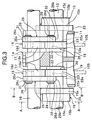
- Fig. 2 is a cross section view showing a variable valve event and lift mechanism (A-A cross section of Fig. 3).
- Fig. 3 is a side elevation view of the variable valve event and lift mechanism.
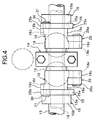
- Fig. 4 is a top plan view of the variable valve event and lift mechanism.
- Fig. 5 is a perspective view showing an eccentric cam for use in the variable valve event and lift mechanism.
- Fig. 6 is a cross section view showing an operation of the variable valve event and lift mechanism at a low lift condition (B-B cross section view of Fig. 3).
- Fig. 7 is a cross section view showing an operation of the variable valve event and lift mechanism at a high lift condition (B-B cross section view of Fig. 3).
- Fig. 8 is a valve lift characteristic diagram corresponding to a base end face and a cam surface of a swing cam in the variable valve event and lift mechanism.
- Fig. 9 is a characteristic diagram showing valve timing and a valve lift of the variable valve event and lift mechanism.
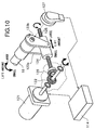
- Fig. 10 is a perspective view showing a rotational driving mechanism of a control shaft in the variable valve event and lift mechanism.
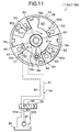
- Fig. 11 is a longitudinal cross section view of a variable valve timing mechanism.
- Fig. 12 is a control block diagram showing an intake air amount control.
- Fig. 13 is a control block diagram showing a control section of the variable valve event and lift mechanism on an intake side.
- Fig. 14 is a control block diagram showing a control section of the variable valve event and lift mechanism on an exhaust side.
- Fig. 15 is a graph showing a correlation between valve timing and a maximum valve lift amount of an exhaust valve.
- Fig. 1 is a structural diagram of an engine for vehicle in embodiments.
- an electronically controlled throttle 104 is disposed for driving a throttle valve 103b to open and close by a throttle motor 103a.
- Air is sucked into a combustion chamber 106 via electronically controlled throttle 104 and an intake valve 105.
- a combusted exhaust gas of engine 101 is discharged from combustion chamber 106 via an exhaust valve 107, purified by a front catalyst 108 and a rear catalyst 109, and then emitted into the atmosphere.
- a valve lift amount and a valve operating angle of intake valve 105 is varied continuously by a variable valve event and lift mechanism 112a, and a phase thereof during valve opening period is varied continuously by a variable valve timing mechanism 113a. While a valve lift amount and a valve operating angle of exhaust valve 107 is varied continuously by a variable valve event and lift mechanism 112b, and a phase thereof during valve opening period is varied continuously by a variable valve timing mechanism 113b.
- An engine control unit (ECU) 114 incorporating therein a microcomputer, controls electronically controlled throttle 104, variable valve event and lift mechanism 112a and variable valve timing mechanism 113a, so that an intake air amount corresponding to an accelerator opening can be obtained.
- ECU engine control unit
- engine control unit 114 controls variable valve event and lift mechanism 112b and variable valve timing mechanism 113b for exhaust valve 107 corresponding to an open-close characteristic of intake valve 105.
- Engine control unit 114 receives various detection signals from an air flow meter 115 detecting an intake air amount Q of engine 101, an accelerator pedal sensor APS 116 detecting an opening APO of an accelerator pedal, a crank angle sensor 117 taking out a rotation signal from a crankshaft 120, a throttle sensor 118 detecting an opening TVO of throttle valve 103b, a water temperature sensor 119 detecting a cooling water temperature Tw of engine 101, and the like.
- an engine rotation speed Ne is calculated based on the rotation signal output from crank angle sensor 117.
- an electromagnetic fuel injection valve 131 is disposed on an intake port 130 at the upstream side of intake valve 105 of each cylinder.
- Fuel injection valve 131 injects fuel adjusted at a predetermined pressure toward intake valve 105 when driven to open by an injection pulse signal from engine control unit 114.
- Fig. 2 to Fig. 4 show in detail the structures of variable valve event and lift mechanisms 112a and 112b.
- Variable valve event and lift mechanism 112a on the intake valve 105 side has the same structure as that of variable valve event and lift mechanism 112b on the exhaust valve 107 side.
- variable valve event and lift mechanism 112a on the intake valve 105 side will be described, and the description of variable valve event and lift mechanism 112b on the exhaust valve 107 side will be omitted.
- variable valve event and lift mechanisms 112a and 112b for varying valve lift amounts of intake valve 105 and exhaust valve 107, respectively, are not limited to the structure as shown in Fig. 2 to Fig. 4.
- Variable valve event and lift mechanism 112 shown in Fig. 2 to Fig. 4 includes a pair of intake valves 105, 105, a camshaft (drive shaft) 13 rotatably supported by a cam bearing 14 of a cylinder head 11, two eccentric cams (drive cams) 15, 15 axially supported by camshaft 13, a control shaft 16 rotatably supported by cam bearing 14 and arranged in parallel at an upper position of camshaft 13, a pair of rocker arms 18, 18 swingingly supported by control shaft 16 through a control cam 17, and a pair of swing cams 20, 20 disposed to upper end portions of intake valves 105, 105 through valve lifters 19, 19, respectively.
- Eccentric cams 15, 15 are connected with rocker arms 18, 18 by link arms 25, 25, respectively.
- Rocker arms 18,18 are connected with swing cams 20, 20 by link members 26, 26.
- Rocker arms 18, 18, link arms 25, 25, and link members 26, 26 constitute a transmission mechanism.
- Each eccentric cam 15, as shown in Fig. 5, is formed in a substantially ring shape and includes a cam body 15a of small diameter, a flange portion 15b integrally formed on an outer surface of cam body 15a.
- An insertion hole 15c is formed through the interior of eccentric cam 15 in an axial direction, and also a center axis X of cam body 15a is biased from a center axis Y of camshaft 13 by a predetermined amount.
- Eccentric cams 15, 15 are pressed and fixed to camshaft 13 via camshaft insertion holes 15c so as to position at outsides of valve lifters 19, 19, respectively.
- Each rocker arm 18, as shown in Fig. 4, is bent and formed in a substantially crank shape, and a central base portion 18a thereof is rotatably supported by control cam 17.
- a pin hole 18d is formed through one end portion 18b which is formed to protrude from an outer end portion of base portion 18a.
- a pin 21 to be connected with a tip portion of link arm 25 is pressed into pin hole 18d.
- a pin hole 18e is formed through the other end portion 18c which is formed to protrude from an inner end portion of base portion 18a.
- a pin 28 to be connected with one end portion 26a (to be described later) of each link member 26 is pressed into pin hole 18e.
- Control cam 17 is formed in a cylindrical shape and fixed to a periphery of control shaft 16. As shown in Fig. 2, a center axis P1 position of control cam 17 is biased from a center axis P2 position of control shaft 16 by ⁇ .
- Swing cam 20 is formed in a substantially lateral U-shape as shown in Fig. 2, Fig. 6 and Fig. 7, and a supporting hole 22a is formed through a substantially ring-shaped base end portion 22.
- Camshaft 13 is inserted into supporting hole 22a to be rotatably supported.
- a pin hole 23a is formed through an end portion 23 positioned at the other end portion 18c of rocker arm 18.
- Base circular surface 24a and cam surface 24b are in contact with a predetermined position of an upper surface of each valve lifter 19 corresponding to a swing position of swing cam 20.
- a predetermined angle range ⁇ 1 of base circular surface 24a is a base circle interval and a range of from base circle interval ⁇ 1 of cam surface 24b to a predetermined angle range ⁇ 2 is a so-called ramp interval, and a range of from ramp interval ⁇ 2 of cam surface 24b to a predetermined angle range ⁇ 3 is a lift interval.
- Link arm 25 includes a ring-shaped base portion 25a and a protrusion end 25b protrudingly formed on a predetermined position of an outer surface of base portion 25a.
- a fitting hole 25c to be rotatably fitted with the outer surface of cam body 15a of eccentric cam 15 is formed on a central position of base portion 25a.
- a pin hole 25d into which pin 21 is rotatably inserted is formed through protrusion end 25b.
- Link member 26 is formed in'a linear shape of predetermined length and pin insertion holes 26c, 26d are formed through both circular end portions 26a, 26b. End portions of pins 28, 29 pressed into pin hole 18d of the other end portion 18c of rocker arm 18 and pin hole 23a of end portion 23 of swing cam 20, respectively, are rotatably inserted into pin insertion holes 26c, 26d.
- Snap rings 30, 31, 32 restricting axial transfer of link arm 25 and link member 26 are disposed on respective end portions of pins 21, 28, 29.
- Control shaft 16 is driven to rotate within a predetermined angle range by a DC servo motor (actuator) 121 as shown in Fig. 10.
- DC servo motor 121 is arranged so that the rotation shaft thereof is parallel to control shaft 16, and a bevel gear 122 is axially supported by the tip portion of the rotation shaft.
- a pair of stays 123a, 123b are fixed to the tip end of control shaft 16.
- a nut 124 is swingingly supported around an axis parallel to control shaft 16 connecting the tip portions of the pair of stays 123a, 123b.
- a bevel gear 126 meshed with bevel gear 122 is axially supported at the tip end of a threaded rod 125 engaged with nut 124. Threaded rod 126 is rotated by the rotation of DC servo motor 121, and the position of nut 124 engaged with threaded rod 125 is displaced in an axial direction of threaded rod 125, so that control shaft 16 is rotated.
- valve lift amount is decreased as the position of nut 124 approaches bevel gear 126, while the valve lift amount is increased as the position of nut 124 gets away from bevel gear 126.
- a potentiometer type operating angle sensor 127 detecting the operating angle of control shaft 16 is disposed on the tip end of control shaft 16, as shown in Fig. 10.
- Control unit 114 feedback controls DC servo motor (actuator) 121 so that an actual operating angle detected by operating angle sensor 127 coincides with a target operating angle.
- variable valve timing mechanism 113a on intake valve 105 side and variable valve timing mechanism 113b on exhaust valve 107 side will be described based on Fig. 11.
- Variable valve timing mechanism 113a on the intake valve 105 side has the same structure as that of variable valve timing mechanism 113b on the exhaust valve 107 side.
- variable valve timing mechanisms 113a and 113b are not limited to the structure as shown in Fig. 10, and may be of a structure that varies continuously a rotation phase of camshaft relative to crankshaft.
- variable valve timing mechanisms 113a and 113b in this embodiment is a so-called vane type variable valve timing mechanism, and comprises: a cam sprocket 51 (timing sprocket) which is rotatably driven by a crankshaft 120 via a timing chain; a rotation member 53 secured to an end portion of a camshaft and rotatably housed inside cam sprocket 51; a hydraulic circuit 54 that relatively rotates rotation member 53 with respect to cam sprocket 51; and a lock mechanism 60 that selectively locks a relative rotation position between cam sprocket 51 and rotation member 53 at predetermined positions.
- a cam sprocket 51 timing sprocket
- rotation member 53 secured to an end portion of a camshaft and rotatably housed inside cam sprocket 51
- a hydraulic circuit 54 that relatively rotates rotation member 53 with respect to cam sprocket 51
- a lock mechanism 60 that selectively locks a relative rotation position between cam sprocket 51 and rotation
- Cam sprocket 51 comprises: a rotation portion (not shown in the figure) having on an outer periphery thereof, teeth for engaging with timing chain (or timing belt); a housing 56 located forward of the rotation portion, for rotatably housing rotation member 53; and a front cover and a rear cover (not shown in the figure) for closing the front and rear openings of housing 56.
- Housing 56 presents a cylindrical shape formed with both front and rear ends open and with four partition portions 63 protrudingly provided at positions on the inner peripheral face at 90° in the circumferential direction, four partition portions 63 presenting a trapezoidal shape in transverse section and being respectively provided along the axial direction of housing 56.
- Rotation member 53 is secured to the front end portion of camshaft and comprises an annular base portion 77 having four vanes 78a, 78b, 78c, and 78d provided on an outer peripheral face of base portion 77 at 90° in the circumferential direction.
- First through fourth vanes 78a to 78d present respective cross-sections of approximate trapezoidal shapes.
- the vanes are disposed in recess portions between each partition portion 63 so as to form spaces in the recess portions to the front and rear in the rotation direction.
- An advance angle side hydraulic chambers 82 and a retarded angle side hydraulic chambers 83 are thus formed.
- Lock mechanism 60 has a construction such that a lock pin 84 is inserted into an engagement hole (not shown in the figure) at a rotation position (in the reference operating condition) on the maximum retarded angle side of rotation member 53.
- Hydraulic circuit 54 has a dual system oil pressure passage, namely a first oil pressure passage 91 for supplying and discharging oil pressure with respect to advance angle side hydraulic chambers 82, and a second oil pressure passage 92 for supplying and discharging oil pressure with respect to retarded angle side hydraulic chambers 83.
- An engine driven oil pump 97 for pumping oil in an oil pan 96 is provided in supply passage 93, and the downstream ends of drain passages 94a and 94b are communicated with oil pan 96.
- First oil pressure passage 91 is formed substantially radially in a base 77 of rotation member 53, and connected to four branching paths 91d communicating with each advance angle side hydraulic chamber 82.
- Second oil pressure passage 92 is connected to four oil galleries 92d opening to each retarded angle side hydraulic chamber 83.
- an internal spool valve is arranged so as to control the switching between respective oil pressure passages 91 and 92, and supply passage 93 and drain passages 94a and 94b.
- Engine control unit 114 controls the power supply quantity for an electromagnetic actuator 99 that drives electromagnetic switching valve 95, based on a duty control signal superimposed with a dither signal.
- rotation member 53 is rotated to the full to the advance angle side by means of vanes 78a to 78d. Due to this, the valve opening period is advanced relative to the rotation phase angle of crankshaft.
- engine control unit 114 comprises a target volume flow ratio calculating section A, an intake side VEL control section B, a throttle control section C and an exhaust side VEL control section D.
- a target volume flow ratio TQH0ST target intake air amount of engine 101 is calculated in the following manner.
- a requested air amount Q0 corresponding to accelerator opening APO and engine rotation speed Ne is calculated, and also a requested ISC air amount QISC requested in an idle rotation speed control (ISC) is calculated.
- TQH0ST Q/(Ne ⁇ VOL#)
- target volume flow ratio TQH0ST is corrected according to an intake negative pressure.
- a target operating angle TGVEL (intake side target valve lift amount) of control shaft 16 in intake side variable valve event and lift mechanism 112a is calculated, based on a post-corrected target volume flow ratio TQH0VEL and a correction value based on valve timing controlled by variable valve timing mechanism 113a.
- DC servo motor 121 in variable valve event and lift mechanism 112a is feedback controlled, so that an actual operating angle coincides with intake side target operating angle TGVEL (intake side target valve lift amount).
- a volume flow ratio requested for throttle valve 103b is calculated to control the intake negative pressure to be constant.
- intake side target operating angle TGVEL is controlled to be equal to or above a minimum lift amount (minimum operating angle) in variable valve event and lift mechanism 112a.
- a smaller one is selected from the volume flow ratio for controlling the intake negative pressure to be constant and the volume flow ratio for compensating for an excess portion of volume flow ratio controlled by intake valve 105, and the selected volume flow ratio is converted into a target angle TGTVO of throttle valve 103b.
- throttle motor 103a is feedback controlled so that an angle (opening) of throttle valve 103b coincides with target angle TGTVO.
- FIG. 13 shows the detail of intake side VEL control section B.
- Target volume flow ratio TQH0ST is corrected by a correction value KMNIQH0 according to the intake negative pressure (valve upstream pressure).
- a larger one is selected from a post-corrected target volume flow ratio TQH0VEL0 and a minimum volume flow ratio QH0LMT controllable by means of a valve lift amount control by variable valve event and lift mechanism 112a, to be output as target volume flow ratio TQH0VEL.
- a throttle amount of throttle valve 103b is set for obtaining target volume flow ratio TQH0VEL in throttle control section B.
- the volume flow ratio is controlled to target volume flow ratio TQH0VEL.
- Target volume flow ratio TQH0VEL is converted into a state amount VAACDNV, and further multiplied by engine rotation speed Ne and discharge amount (entire cylinder volume) VOL#, to be converted into an entire opening area TVLAACD requested for intake valve 105.
- Entire opening area TVELAACD is corrected based on a valve lift amount VELCOM, and flow loss coefficients Cd and KAVTC according to valve timing, to be output as a requested opening area TVELAA, and further converted into target operating angle TGVEL.
- target operating angle TGVEL as shown in Fig. 14, is subjected to a limitation according to valve timing VTCNOW by variable valve timing mechanism 113a.
- DC servo motor 121 in variable valve event and lift mechanism 112a is feedback controlled.
- opening timing IVOREAL of intake valve 105 is calculated based on an actual operating angle VCS-ANGL as a control result and valve timing VTCNOW, to be output to exhaust side VEL control section D.
- variable valve timing mechanisms 113a and 113b are controlled according to an engine load (target volume flow ratio TQH0ST) and engine rotation speed.
- FIG. 14 shows the detail of exhaust side VEL control section D, that controls variable valve event lift mechanism 112b and variable valve timing mechanism 113b on the exhaust side.
- a first minimum valve lift amount TGEVLLL0 is set according to engine rotation speed Ne, and also a second minimum valve lift amount TGEVLLL1 is set based on target volume flow ratio TQH0ST.
- a larger one in first minimum valve lift amount TGEVLLL0 and second minimum valve lift amount TGEVLLL1 is output as a minimum valve lift amount (minimum operating angle) TGEVLLL of exhaust valve 107.
- First minimum valve lift amount TGEVLLL0 is set to be a larger value as engine rotation speed Ne is higher.
- variable valve event and lift mechanisms 112a and 112b in this embodiment since an allowable rotation speed is lower as the valve lift amount is smaller, if a high rotation operation is performed under a state of low valve lift amount, there may occur a failure of mechanism.
- valve lift amount is limited to be equal to or above an amount having durability to engine rotation speed Ne, by first minimum valve lift amount TGEVLLL0.
- second minimum valve lift amount TGEVLLL1 is a minimum valve lift amount required for gas exchange at target volume flow ratio TQH0ST.
- a maximum valve lift amount (maximum operating angle) of exhaust valve 107 is set based on opening timing IVO of intake valve 105.
- a retarded angle side limit value EVCLIM0 (refer to Fig. 15) at closing timing EVC of exhaust valve 107 in the case where valve timing of exhaust valve 107 is controlled to the most retarded angle side is calculated.
- a maximum valve lift amount (maximum operating angle) TGEVELLH is set.
- maximum valve lift amount (maximum operating angle) TGEVELLH is the valve lift (operating angle) wherein closing timing EVC of exhaust valve 107 reaches retarded angle side limit value EVCLIM0 at the valve timing at that time, and becomes larger as the valve timing is further advanced (refer to Fig. 15).
- closing timing EVC is limited to maximum valve lift amount (maximum operating angle) TGEVELLH or less, closing timing EVC is not delayed than retarded side limit value EVCLIM0. Thereby, a valve overlap amount is restricted within an allowable value, to avoid valve interference or degradation of combustibility.
- Exhaust side VEL limiter control section is input with target operating angle TGEVEL0 of exhaust valve 107 obtained by converting requested opening area TVELAA, minimum valve lift amount (minimum operating angle) TGEVLLL and maximum valve lift amount (maximum operating angle) TGEVELLH.
- exhaust side VEL limiter control section outputs minimum valve lift amount (minimum operating angle) TGEVLLL as target operating angle TGEVEL.
- target operating angle TGEVEL0 exceeds maximum valve lift amount (maximum operating angle) TGEVLLH
- maximum valve lift amount (maximum operating angle) TGEVLLH is output as target operating angle TGEVEL.
- target operating angle TGEVEL0 is more than minimum valve lift amount (minimum operating angle) TGEVLLL and also less than maximum valve lift amount (maximum operating angle) TGEVLLH
- target operating angle TGEVEL0 is output as it is, as target operating angle TGEVEL.
- DC servo motor 121 in exhaust side variable valve event and lift mechanism 112b is feedback controlled.
- target operating angle TGEVEL is limited by maximum valve lift amount (maximum operating angle) TGEVELLH, an opening area of exhaust valve corresponding to target volume flow ratio TQH0ST cannot be obtained, and there occurs a possibility of failure in variable valve event and lift mechanism 112b.
- valve timing of exhaust valve 107 is corrected to be advanced, since a center position of opening period of exhaust valve 107 is advanced, an angle of from the center position of opening period to retarded angle side limit value EVCLIM0 becomes larger, so that maximum valve lift amount (maximum operating angle) with retarded angle side limit value EVCLIM0 as closing timing EVC is set to be larger (refer to Fig. 15).
Abstract
Description
- The present invention relates to an apparatus and a method for controlling a variable valve mechanism, in an internal combustion engine provided with an intake side variable valve mechanism varying an open-close characteristic of an intake valve and an exhaust side variable valve mechanism varying an open-close characteristic of an exhaust valve.
- Heretofore, there has been known an apparatus in which a target torque is calculated based on an accelerator opening and an engine rotation speed, and an open-close characteristic of an intake valve is varied so that a target intake air amount corresponding to the target torque can be obtained (refer to Japanese Unexamined Patent Publication No. 6-272580).
- Further, there has also been known a variable valve event and lift mechanism varying continuously valve lift amounts and operating angles of engine valves (intake valve and exhaust valve) (refer to Japanese Unexamined Patent Publication No. 2001-012262)
- In the case where an open-close characteristic of an intake valve (valve lift amount and/or valve timing) is variably controlled so as to obtain a target intake air amount, it becomes necessary to change the open-close characteristic of the intake valve over a wide range.
- Consequently, there is a possibility that interference between the intake valve and exhaust valve occurs or the combustibility is degraded due to a change in valve overlap amount.
- The present invention has been accomplished in view of the above problems and has an object to avoid interference between valves or combustibility degradation, while controlling an open-close characteristic of an intake valve to a requested characteristic according to operating conditions.
- In order to achieve the above object, according to the present invention, the constitution is such that an open-close characteristic of an intake valve is determined based on operating conditions of an internal combustion engine to control an intake side variable valve mechanism, and also an open-close characteristic of an exhaust valve is determined according to the open-close characteristic of the intake valve to control an exhaust side variable valve mechanism.
- The other objects and features of this invention will become understood from the following description with reference to the accompanying drawings.
- Fig. 1 is a diagram of a system structure of an internal combustion engine.
- Fig. 2 is a cross section view showing a variable valve event and lift mechanism (A-A cross section of Fig. 3).
- Fig. 3 is a side elevation view of the variable valve event and lift mechanism.
- Fig. 4 is a top plan view of the variable valve event and lift mechanism.
- Fig. 5 is a perspective view showing an eccentric cam for use in the variable valve event and lift mechanism.
- Fig. 6 is a cross section view showing an operation of the variable valve event and lift mechanism at a low lift condition (B-B cross section view of Fig. 3).
- Fig. 7 is a cross section view showing an operation of the variable valve event and lift mechanism at a high lift condition (B-B cross section view of Fig. 3).
- Fig. 8 is a valve lift characteristic diagram corresponding to a base end face and a cam surface of a swing cam in the variable valve event and lift mechanism.
- Fig. 9 is a characteristic diagram showing valve timing and a valve lift of the variable valve event and lift mechanism.
- Fig. 10 is a perspective view showing a rotational driving mechanism of a control shaft in the variable valve event and lift mechanism.
- Fig. 11 is a longitudinal cross section view of a variable valve timing mechanism.
- Fig. 12 is a control block diagram showing an intake air amount control.
- Fig. 13 is a control block diagram showing a control section of the variable valve event and lift mechanism on an intake side.
- Fig. 14 is a control block diagram showing a control section of the variable valve event and lift mechanism on an exhaust side.
- Fig. 15 is a graph showing a correlation between valve timing and a maximum valve lift amount of an exhaust valve.
- Fig. 1 is a structural diagram of an engine for vehicle in embodiments.
- In an
intake passage 102 of anengine 101, an electronically controlledthrottle 104 is disposed for driving athrottle valve 103b to open and close by athrottle motor 103a. - Air is sucked into a
combustion chamber 106 via electronically controlledthrottle 104 and anintake valve 105. - A combusted exhaust gas of
engine 101 is discharged fromcombustion chamber 106 via anexhaust valve 107, purified by afront catalyst 108 and arear catalyst 109, and then emitted into the atmosphere. - A valve lift amount and a valve operating angle of
intake valve 105 is varied continuously by a variable valve event andlift mechanism 112a, and a phase thereof during valve opening period is varied continuously by a variablevalve timing mechanism 113a. While a valve lift amount and a valve operating angle ofexhaust valve 107 is varied continuously by a variable valve event andlift mechanism 112b, and a phase thereof during valve opening period is varied continuously by a variablevalve timing mechanism 113b. - An engine control unit (ECU) 114 incorporating therein a microcomputer, controls electronically controlled
throttle 104, variable valve event andlift mechanism 112a and variablevalve timing mechanism 113a, so that an intake air amount corresponding to an accelerator opening can be obtained. - Further,
engine control unit 114 controls variable valve event andlift mechanism 112b and variablevalve timing mechanism 113b forexhaust valve 107 corresponding to an open-close characteristic ofintake valve 105. -
Engine control unit 114 receives various detection signals from anair flow meter 115 detecting an intake air amount Q ofengine 101, an acceleratorpedal sensor APS 116 detecting an opening APO of an accelerator pedal, acrank angle sensor 117 taking out a rotation signal from acrankshaft 120, athrottle sensor 118 detecting an opening TVO ofthrottle valve 103b, awater temperature sensor 119 detecting a cooling water temperature Tw ofengine 101, and the like. - In
engine control unit 114, an engine rotation speed Ne is calculated based on the rotation signal output fromcrank angle sensor 117. - Further, an electromagnetic
fuel injection valve 131 is disposed on anintake port 130 at the upstream side ofintake valve 105 of each cylinder. -
Fuel injection valve 131 injects fuel adjusted at a predetermined pressure towardintake valve 105 when driven to open by an injection pulse signal fromengine control unit 114. - Fig. 2 to Fig. 4 show in detail the structures of variable valve event and
lift mechanisms - Variable valve event and
lift mechanism 112a on theintake valve 105 side has the same structure as that of variable valve event andlift mechanism 112b on theexhaust valve 107 side. - Accordingly, in the following, variable valve event and
lift mechanism 112a on theintake valve 105 side will be described, and the description of variable valve event andlift mechanism 112b on theexhaust valve 107 side will be omitted. - However, variable valve event and
lift mechanisms intake valve 105 andexhaust valve 107, respectively, are not limited to the structure as shown in Fig. 2 to Fig. 4. - Variable valve event and lift mechanism 112 shown in Fig. 2 to Fig. 4 includes a pair of
intake valves cylinder head 11, two eccentric cams (drive cams) 15, 15 axially supported by camshaft 13, acontrol shaft 16 rotatably supported by cam bearing 14 and arranged in parallel at an upper position ofcamshaft 13, a pair ofrocker arms control shaft 16 through acontrol cam 17, and a pair ofswing cams intake valves valve lifters -
Eccentric cams rocker arms link arms -
Rocker arms swing cams link members -
Rocker arms arms link members - Each
eccentric cam 15, as shown in Fig. 5, is formed in a substantially ring shape and includes acam body 15a of small diameter, aflange portion 15b integrally formed on an outer surface ofcam body 15a. - An
insertion hole 15c is formed through the interior ofeccentric cam 15 in an axial direction, and also a center axis X ofcam body 15a is biased from a center axis Y ofcamshaft 13 by a predetermined amount. -
Eccentric cams camshaft insertion holes 15c so as to position at outsides ofvalve lifters - Each
rocker arm 18, as shown in Fig. 4, is bent and formed in a substantially crank shape, and acentral base portion 18a thereof is rotatably supported bycontrol cam 17. - A
pin hole 18d is formed through oneend portion 18b which is formed to protrude from an outer end portion ofbase portion 18a. Apin 21 to be connected with a tip portion oflink arm 25 is pressed intopin hole 18d. - A
pin hole 18e is formed through theother end portion 18c which is formed to protrude from an inner end portion ofbase portion 18a. Apin 28 to be connected with oneend portion 26a (to be described later) of eachlink member 26 is pressed intopin hole 18e. -
Control cam 17 is formed in a cylindrical shape and fixed to a periphery ofcontrol shaft 16. As shown in Fig. 2, a center axis P1 position ofcontrol cam 17 is biased from a center axis P2 position ofcontrol shaft 16 by α. -
Swing cam 20 is formed in a substantially lateral U-shape as shown in Fig. 2, Fig. 6 and Fig. 7, and a supportinghole 22a is formed through a substantially ring-shapedbase end portion 22. Camshaft 13 is inserted into supportinghole 22a to be rotatably supported. Also, apin hole 23a is formed through anend portion 23 positioned at theother end portion 18c ofrocker arm 18. - A base
circular surface 24a ofbase end portion 22 side and acam surface 24b extending in an arc shape from basecircular surface 24a to an edge ofend portion 23, are formed on a bottom surface ofswing cam 20. Basecircular surface 24a andcam surface 24b are in contact with a predetermined position of an upper surface of eachvalve lifter 19 corresponding to a swing position ofswing cam 20. - Namely, according to a valve lift characteristic shown in Fig. 8, as shown in Fig. 2, a predetermined angle range 1 of base
circular surface 24a is a base circle interval and a range of from base circle interval 1 ofcam surface 24b to a predetermined angle range 2 is a so-called ramp interval, and a range of from ramp interval 2 ofcam surface 24b to a predetermined angle range 3 is a lift interval. -
Link arm 25 includes a ring-shaped base portion 25a and aprotrusion end 25b protrudingly formed on a predetermined position of an outer surface ofbase portion 25a. Afitting hole 25c to be rotatably fitted with the outer surface ofcam body 15a ofeccentric cam 15 is formed on a central position ofbase portion 25a. Also, a pin hole 25d into whichpin 21 is rotatably inserted is formed throughprotrusion end 25b. -
Link member 26 is formed in'a linear shape of predetermined length andpin insertion holes circular end portions pins pin hole 18d of theother end portion 18c ofrocker arm 18 andpin hole 23a ofend portion 23 ofswing cam 20, respectively, are rotatably inserted intopin insertion holes - Snap rings 30, 31, 32 restricting axial transfer of
link arm 25 andlink member 26 are disposed on respective end portions ofpins - In such a constitution, depending on a positional relation between the center axis P2 of
control shaft 16 and the center axis P1 ofcontrol cam 17, as shown in Fig. 6 and Fig. 7, the valve lift amount is varied, and by drivingcontrol shaft 16 to rotate, the position of the center axis P2 ofcontrol shaft 16 relative to the center axis P1 ofcontrol cam 17 is changed. -
Control shaft 16 is driven to rotate within a predetermined angle range by a DC servo motor (actuator) 121 as shown in Fig. 10. - By varying an operating angle of
control shaft 16 byDC servo motor 121, the valve lift amount and valve operating angle of each ofintake valves - In this embodiment, the larger the operating angle of
control shaft 16 becomes, the larger the lift amount ofintake valve 105 becomes. - In Fig. 10,
DC servo motor 121 is arranged so that the rotation shaft thereof is parallel to controlshaft 16, and abevel gear 122 is axially supported by the tip portion of the rotation shaft. - On the other hand, a pair of
stays control shaft 16. Anut 124 is swingingly supported around an axis parallel to controlshaft 16 connecting the tip portions of the pair ofstays - A
bevel gear 126 meshed withbevel gear 122 is axially supported at the tip end of a threadedrod 125 engaged withnut 124. Threadedrod 126 is rotated by the rotation ofDC servo motor 121, and the position ofnut 124 engaged with threadedrod 125 is displaced in an axial direction of threadedrod 125, so thatcontrol shaft 16 is rotated. - Here, the valve lift amount is decreased as the position of
nut 124 approachesbevel gear 126, while the valve lift amount is increased as the position ofnut 124 gets away frombevel gear 126. - Further, a potentiometer type operating
angle sensor 127 detecting the operating angle ofcontrol shaft 16 is disposed on the tip end ofcontrol shaft 16, as shown in Fig. 10. -
Control unit 114 feedback controls DC servo motor (actuator) 121 so that an actual operating angle detected by operatingangle sensor 127 coincides with a target operating angle. - Next, the structures of variable
valve timing mechanism 113a onintake valve 105 side and variablevalve timing mechanism 113b onexhaust valve 107 side will be described based on Fig. 11. - Variable
valve timing mechanism 113a on theintake valve 105 side has the same structure as that of variablevalve timing mechanism 113b on theexhaust valve 107 side. - However, variable
valve timing mechanisms - Each of variable
valve timing mechanisms crankshaft 120 via a timing chain; arotation member 53 secured to an end portion of a camshaft and rotatably housed insidecam sprocket 51; ahydraulic circuit 54 that relatively rotatesrotation member 53 with respect tocam sprocket 51; and alock mechanism 60 that selectively locks a relative rotation position betweencam sprocket 51 androtation member 53 at predetermined positions. -
Cam sprocket 51 comprises: a rotation portion (not shown in the figure) having on an outer periphery thereof, teeth for engaging with timing chain (or timing belt); ahousing 56 located forward of the rotation portion, for rotatablyhousing rotation member 53; and a front cover and a rear cover (not shown in the figure) for closing the front and rear openings ofhousing 56. -
Housing 56 presents a cylindrical shape formed with both front and rear ends open and with fourpartition portions 63 protrudingly provided at positions on the inner peripheral face at 90° in the circumferential direction, fourpartition portions 63 presenting a trapezoidal shape in transverse section and being respectively provided along the axial direction ofhousing 56. -
Rotation member 53 is secured to the front end portion of camshaft and comprises anannular base portion 77 having fourvanes base portion 77 at 90° in the circumferential direction. - First through
fourth vanes 78a to 78d present respective cross-sections of approximate trapezoidal shapes. The vanes are disposed in recess portions between eachpartition portion 63 so as to form spaces in the recess portions to the front and rear in the rotation direction. An advance angle sidehydraulic chambers 82 and a retarded angle sidehydraulic chambers 83 are thus formed. -
Lock mechanism 60 has a construction such that alock pin 84 is inserted into an engagement hole (not shown in the figure) at a rotation position (in the reference operating condition) on the maximum retarded angle side ofrotation member 53. -
Hydraulic circuit 54 has a dual system oil pressure passage, namely a firstoil pressure passage 91 for supplying and discharging oil pressure with respect to advance angle sidehydraulic chambers 82, and a secondoil pressure passage 92 for supplying and discharging oil pressure with respect to retarded angle sidehydraulic chambers 83. - To these two
oil pressure passages supply passage 93 anddrain passages electromagnetic switching valve 95 for switching the passages. - An engine driven
oil pump 97 for pumping oil in anoil pan 96 is provided insupply passage 93, and the downstream ends ofdrain passages oil pan 96. - First
oil pressure passage 91 is formed substantially radially in abase 77 ofrotation member 53, and connected to four branchingpaths 91d communicating with each advance angle sidehydraulic chamber 82. Secondoil pressure passage 92 is connected to fouroil galleries 92d opening to each retarded angle sidehydraulic chamber 83. - With
electromagnetic switching valve 95, an internal spool valve is arranged so as to control the switching between respectiveoil pressure passages supply passage 93 anddrain passages -
Engine control unit 114 controls the power supply quantity for anelectromagnetic actuator 99 that driveselectromagnetic switching valve 95, based on a duty control signal superimposed with a dither signal. - For example, when a control signal of duty ratio 0% (OFF signal) is output to
electromagnetic actuator 99, the hydraulic fluid pumped from oil pump 47 is supplied to retarded angle sidehydraulic chambers 83 via secondoil pressure passage 92, and the hydraulic fluid in advance angle sidehydraulic chambers 82 is discharged intooil pan 96 fromfirst drain passage 94a via firstoil pressure passage 91. - Consequently, an inner pressure of retarded angle side
hydraulic chambers 83 becomes a high pressure while an inner pressure of advance angle sidehydraulic chambers 82 becomes a low pressure, androtation member 53 is rotated to the most retarded angle side by means ofvanes 78a to 78d. The result of this is that a valve opening period is delayed relative to a rotation phase angle of crankshaft. - On the other hand, when a control signal of duty ratio 100% (ON signal) is output to
electromagnetic actuator 99, the hydraulic fluid is supplied to inside of advance angle sidehydraulic chambers 82 via firstoil pressure passage 91, and the hydraulic fluid in retarded angle sidehydraulic chambers 83 is discharged tooil pan 96 via secondoil pressure passage 92, andsecond drain passage 94b, so that retarded angle sidehydraulic chambers 83 become a low pressure. - Therefore,
rotation member 53 is rotated to the full to the advance angle side by means ofvanes 78a to 78d. Due to this, the valve opening period is advanced relative to the rotation phase angle of crankshaft. - Next, there will be described controls of each of variable valve event and
lift mechanisms valve timing mechanisms - As shown in Fig. 12,
engine control unit 114 comprises a target volume flow ratio calculating section A, an intake side VEL control section B, a throttle control section C and an exhaust side VEL control section D. - In target volume flow ratio calculating section A, a target volume flow ratio TQH0ST (target intake air amount) of
engine 101 is calculated in the following manner. - Firstly, a requested air amount Q0 corresponding to accelerator opening APO and engine rotation speed Ne is calculated, and also a requested ISC air amount QISC requested in an idle rotation speed control (ISC) is calculated.
- Then, a sum of requested air amount Q0 and requested ISC air amount QISC is obtained as a total requested air amount Q.
- The resultant total requested air amount Q is divided by engine rotation speed Ne and an effective discharge amount (entire cylinder volume) VOL# to calculate target volume flow ratio TQH0ST.
- In intake side VEL control section B, target volume flow ratio TQH0ST is corrected according to an intake negative pressure.
- Further, a target operating angle TGVEL (intake side target valve lift amount) of
control shaft 16 in intake side variable valve event andlift mechanism 112a is calculated, based on a post-corrected target volume flow ratio TQH0VEL and a correction value based on valve timing controlled by variablevalve timing mechanism 113a. - Then,
DC servo motor 121 in variable valve event andlift mechanism 112a is feedback controlled, so that an actual operating angle coincides with intake side target operating angle TGVEL (intake side target valve lift amount). - In throttle control section C, a volume flow ratio requested for
throttle valve 103b is calculated to control the intake negative pressure to be constant. - Further, intake side target operating angle TGVEL is controlled to be equal to or above a minimum lift amount (minimum operating angle) in variable valve event and
lift mechanism 112a. - Therefore, when intake side target operating angle TGVEL (intake side target valve lift amount) larger than a value equivalent to target volume flow ratio TQH0ST is set, a volume flow ratio for compensating for an excess portion of volume flow ratio is calculated in throttle control section C.
- Here, a smaller one is selected from the volume flow ratio for controlling the intake negative pressure to be constant and the volume flow ratio for compensating for an excess portion of volume flow ratio controlled by
intake valve 105, and the selected volume flow ratio is converted into a target angle TGTVO ofthrottle valve 103b. - Then,
throttle motor 103a is feedback controlled so that an angle (opening) ofthrottle valve 103b coincides with target angle TGTVO. - A block diagram in Fig. 13 shows the detail of intake side VEL control section B.
- Target volume flow ratio TQH0ST is corrected by a correction value KMNIQH0 according to the intake negative pressure (valve upstream pressure).
- Then, a larger one is selected from a post-corrected target volume flow ratio TQH0VEL0 and a minimum volume flow ratio QH0LMT controllable by means of a valve lift amount control by variable valve event and
lift mechanism 112a, to be output as target volume flow ratio TQH0VEL. - Here, when minimum volume flow ratio QH0LMT is selected, a throttle amount of
throttle valve 103b is set for obtaining target volume flow ratio TQH0VEL in throttle control section B. - Consequently, by performing cooperatively the valve lift amount control of
intake valve 105 and the throttle amount control ofthrottle valve 103b, the volume flow ratio is controlled to target volume flow ratio TQH0VEL. - Target volume flow ratio TQH0VEL is converted into a state amount VAACDNV, and further multiplied by engine rotation speed Ne and discharge amount (entire cylinder volume) VOL#, to be converted into an entire opening area TVLAACD requested for
intake valve 105. - Entire opening area TVELAACD is corrected based on a valve lift amount VELCOM, and flow loss coefficients Cd and KAVTC according to valve timing, to be output as a requested opening area TVELAA, and further converted into target operating angle TGVEL.
- Further, target operating angle TGVEL, as shown in Fig. 14, is subjected to a limitation according to valve timing VTCNOW by variable
valve timing mechanism 113a. - Then, based on the thus limited final target operating angle TGVEL,
DC servo motor 121 in variable valve event andlift mechanism 112a is feedback controlled. - Further, opening timing IVOREAL of
intake valve 105 is calculated based on an actual operating angle VCS-ANGL as a control result and valve timing VTCNOW, to be output to exhaust side VEL control section D. - Note, variable
valve timing mechanisms - A block diagram in Fig. 14 shows the detail of exhaust side VEL control section D, that controls variable valve
event lift mechanism 112b and variablevalve timing mechanism 113b on the exhaust side. - Referring to the block diagram in Fig. 14, in a LOW side limiter setting section, a first minimum valve lift amount TGEVLLL0 is set according to engine rotation speed Ne, and also a second minimum valve lift amount TGEVLLL1 is set based on target volume flow ratio TQH0ST.
- A larger one in first minimum valve lift amount TGEVLLL0 and second minimum valve lift amount TGEVLLL1 is output as a minimum valve lift amount (minimum operating angle) TGEVLLL of
exhaust valve 107. - First minimum valve lift amount TGEVLLL0 is set to be a larger value as engine rotation speed Ne is higher.
- In variable valve event and
lift mechanisms - Therefore, the valve lift amount is limited to be equal to or above an amount having durability to engine rotation speed Ne, by first minimum valve lift amount TGEVLLL0.
- Further, second minimum valve lift amount TGEVLLL1 is a minimum valve lift amount required for gas exchange at target volume flow ratio TQH0ST.
- On the other hand, in a HIGH side limiter setting section, a maximum valve lift amount (maximum operating angle) of
exhaust valve 107 is set based on opening timing IVO ofintake valve 105. - Specifically, at first, based on opening timing IVOREAL of
intake valve 105 output from intake side VEL control section B, a retarded angle side limit value EVCLIM0 (refer to Fig. 15) at closing timing EVC ofexhaust valve 107 in the case where valve timing ofexhaust valve 107 is controlled to the most retarded angle side is calculated. - Then, based on an advance angle amount EVTCNOW of valve timing at that time in
exhaust valve 107, and retarded angle side limit value EVCLIM0, a maximum valve lift amount (maximum operating angle) TGEVELLH is set. - Here, maximum valve lift amount (maximum operating angle) TGEVELLH is the valve lift (operating angle) wherein closing timing EVC of
exhaust valve 107 reaches retarded angle side limit value EVCLIM0 at the valve timing at that time, and becomes larger as the valve timing is further advanced (refer to Fig. 15). - If actual closing timing EVC is limited to maximum valve lift amount (maximum operating angle) TGEVELLH or less, closing timing EVC is not delayed than retarded side limit value EVCLIM0. Thereby, a valve overlap amount is restricted within an allowable value, to avoid valve interference or degradation of combustibility.
- Exhaust side VEL limiter control section is input with target operating angle TGEVEL0 of
exhaust valve 107 obtained by converting requested opening area TVELAA, minimum valve lift amount (minimum operating angle) TGEVLLL and maximum valve lift amount (maximum operating angle) TGEVELLH. - In the case where target operating angle TGEVEL0 is less than minimum valve lift amount (minimum operating angle) TGEVLLL, exhaust side VEL limiter control section outputs minimum valve lift amount (minimum operating angle) TGEVLLL as target operating angle TGEVEL.
- Whereas, in the case where target operating angle TGEVEL0 exceeds maximum valve lift amount (maximum operating angle) TGEVLLH, maximum valve lift amount (maximum operating angle) TGEVLLH is output as target operating angle TGEVEL.
- Further, in the case where target operating angle TGEVEL0 is more than minimum valve lift amount (minimum operating angle) TGEVLLL and also less than maximum valve lift amount (maximum operating angle) TGEVLLH, target operating angle TGEVEL0 is output as it is, as target operating angle TGEVEL.
- Then, based on target operating angle TGEVEL,
DC servo motor 121 in exhaust side variable valve event andlift mechanism 112b is feedback controlled. - Here, in the case of TGEVLLL>TGEVELLH, if target operating angle TGEVEL is limited by minimum valve lift amount (minimum operating angle) TGEVLLL, the valve overlap amount becomes excessive, resulting in valve interference or degradation of combustibility.
- Moreover, if target operating angle TGEVEL is limited by maximum valve lift amount (maximum operating angle) TGEVELLH, an opening area of exhaust valve corresponding to target volume flow ratio TQH0ST cannot be obtained, and there occurs a possibility of failure in variable valve event and
lift mechanism 112b. - Consequently, in the case where TGEVLLL>TGEVELLH, valve timing of
exhaust valve 107 by exhaust side variablevalve timing mechanism 113b is forcibly corrected to be advanced, so as to obtain TGEVLLL=TGEVELLH (or TGEVLLL<TGEVELLH). - When valve timing of
exhaust valve 107 is corrected to be advanced, since a center position of opening period ofexhaust valve 107 is advanced, an angle of from the center position of opening period to retarded angle side limit value EVCLIM0 becomes larger, so that maximum valve lift amount (maximum operating angle) with retarded angle side limit value EVCLIM0 as closing timing EVC is set to be larger (refer to Fig. 15). - The entire contents of Japanese Patent Application No. 2001-331353, filed October 29, 2001, a priority of which is claimed, are incorporated herein by reference.
- While only selected embodimentshave been chosen to illustrate the present invention, it will be apparent to those skilled in the art from this disclosure that various change and modification can be made herein without departing from the scope of the invention as defined in the appended claims.
- Furthermore, the foregoing description of the embodiments according to the present invention are provided for illustration only, and not for the purpose of limiting the invention as defined by the appended claims and their equivalents.
Claims (19)
- A variable valve control apparatus for an internal combustion engine, for varying open-close characteristics of an intake valve and an exhaust valve, said apparatus comprising:an intake side variable valve mechanism that varies the open-close characteristic of said intake valve;an exhaust side variable valve mechanism that varies the open-close characteristic of said exhaust valve;an operating condition detector that detects operating conditions of said internal combustion engine;a control unit that receives a detection signal from said operating condition detector, and outputs control signals to said intake side variable valve mechanism and to said exhaust side variable valve mechanism, based on said detection signal,said apparatus characterized in that said control unit determines the open-close characteristic of said intake valve based on the operating conditions of said internal combustion engine to control said intake side variable valve mechanism, and also determines the open-close characteristic of said exhaust valve according to the open-close characteristic of said intake valve to control said exhaust side variable valve mechanism.
- A variable valve control apparatus for an internal combustion engine according to claim 1,
wherein said control unit sets a most retarded angle position of closing timing of said exhaust valve, based on opening timing of said intake valve, and
controls the closing timing of said exhaust valve to a more advanced angle side than said most retarded angle position. - A variable valve control apparatus for an internal combustion engine according to claim 2,
wherein said exhaust side variable valve mechanism comprises a variable valve event and lift mechanism that varies a valve lift amount as well as a valve operating angle of said exhaust valve, and
said control unit calculates a maximum valve lift amount by which the closing timing of said exhaust valve becomes said most retarded angle position, and limits the valve lift amount of said exhaust valve by said variable valve event and lift mechanism to be equal to or less than said maximum valve lift amount. - A variable valve control apparatus for an internal combustion engine according to claim 2,
wherein said exhaust side variable valve mechanism comprises a variable valve event and lift mechanism that varies a valve lift amount as well as a valve operating angle of said exhaust valve, and
said control unit limits the valve lift amount of said exhaust valve by said variable valve event and lift mechanism to be equal to or less than said maximum valve lift amount and also to be equal to or above a predetermined minimum valve lift amount. - A variable valve control apparatus for an internal combustion engine according to claim 4,
wherein said exhaust side variable valve mechanism comprises, in addition to said variable valve event and lift mechanism, a variable valve timing mechanism that varies the valve timing of said exhaust valve, at the valve operating angle by said variable valve event and lift mechanism, and
said control unit advances the valve timing of said exhaust valve by said variable valve timing mechanism to control said maximum valve lift amount to be equal to or above said predetermined minimum valve lift amount, when said maximum valve lift amount is smaller than said predetermined minimum valve lift amount. - A variable valve control apparatus for an internal combustion engine according to claim 4,
wherein said control unit sets said predetermined minimum valve lift amount according to an engine rotation speed. - A variable valve control apparatus for an internal combustion engine according to claim 4,
wherein said control unit calculates a target intake air amount based on the operating conditions of the internal combustion engine, to control said intake side variable valve mechanism based on said target intake air amount, and
also sets said predetermined minimum valve lift amount according to said target intake air amount. - A variable valve control apparatus for an internal combustion engine according to claim 1,
wherein said control unit calculates a target intake air amount based on the operating conditions of the internal combustion engine, to control said intake side variable valve mechanism based on said target intake air amount. - A variable valve control apparatus for an internal combustion engine according to claim 1,
wherein said intake side variable valve mechanism and said exhaust side variable valve mechanism each comprises a variable valve event and lift mechanism that varies a valve lift amount as well as a valve operating angle,
said variable valve event and lift mechanism comprises:a drive shaft rotating in synchronism with a crankshaft;a drive cam fixed to said drive shaft;a swing cam swinging to operate said valves to open and close;a transmission mechanism with one end connected to said drive cam side and the other end connected to said swing cam side;a control shaft having a control cam changing the position of said transmission mechanism; andan actuator rotating said control shaft, andcontinuously changes the valve lift amount as well as the valve operating angle by rotatably controlling said control shaft by said actuator. - A variable valve control apparatus for an internal combustion engine, for varying open-close characteristics of an intake valve and an exhaust valve, said apparatus comprising:intake side variable valve means for varying the open-close characteristic of said intake valve;exhaust side variable valve means for varying the open-close characteristic of said exhaust valve;operating condition detecting means for detecting operating conditions of said internal combustion engine; andcontrol means for controlling said intake side variable valve means and said exhaust side variable valve means, based on a detection signal from said operating condition detecting means,said apparatus characterized in thatsaid control means determines the open-close characteristic of said intake valve based on the operating conditions to control said intake side variable valve means, and also determines the open-close characteristic of said exhaust valve according to the open-close characteristic of said intake valve to control said exhaust side variable valve means.
- A variable valve control method for an internal combustion engine, for controlling an intake side variable valve mechanism that varies an open-close characteristic of an intake valve and an exhaust side variable valve mechanism that varies an open-close characteristic of an exhaust valve, characterized of comprising the steps of:detecting operating conditions of said internal combustion engine;determining the open-close characteristic said intake valve based on the operating conditions of said internal combustion engine;controlling said intake side variable valve mechanism according to the open-close characteristic;determining the open-close characteristic of said exhaust valve according to the open-close characteristic of said intake valve; andcontrolling said exhaust side variable valve mechanism according to the open-close characteristic of said exhaust valve.
- A variable valve control method for an internal combustion engine according to claim 11,
wherein said step of determining the open-close characteristic of said exhaust valve comprises the steps of:setting a most retarded angle position of closing timing of said exhaust valve, based on opening timing of said intake valve; andcontrolling the closing timing of said exhaust valve to a more advanced angle side than said most retarded angle position. - A variable valve control method for an internal combustion engine according to claim 12,
wherein said exhaust side variable valve mechanism comprises a variable valve event and lift mechanism that varies a valve lift amount as well as a valve operating angle of said exhaust valve, and
said step of controlling the closing timing of said exhaust valve comprises the steps of:calculating a maximum valve lift amount by which the closing timing of said exhaust valve becomes said most retarded angle position; andlimiting the valve lift amount of said exhaust valve by said variable valve event and lift mechanism to be equal to or less than said maximum valve lift amount. - A variable valve control method for an internal combustion engine according to claim 12,
wherein said exhaust side variable valve mechanism comprises a variable valve event and lift mechanism that varies a valve lift amount as well as a valve operating angle of said exhaust valve, and
said step of controlling the closing timing of said exhaust valve comprises the steps of:calculating a maximum valve lift amount by which the closing timing of said exhaust valve becomes said most retarded angle position; andlimiting the valve lift amount of said exhaust valve by said variable valve event and lift mechanism to be equal to or less than said maximum valve lift amount and also to be equal to or above a predetermined minimum valve lift amount. - A variable valve control method for an internal combustion engine according to claim 14,
wherein said exhaust side variable valve mechanism comprises, in addition to said variable valve event and lift mechanism, a variable valve timing mechanism that varies the valve timing of said exhaust valve, at the valve operating angle by said variable valve event and lift mechanism, and
said step of calculating the maximum value lift amount comprises the steps of:controlling said variable valve timing mechanism to advance the valve timing of said exhaust valve, when said maximum valve lift amount is smaller than said predetermined minimum valve lift amount; andcalculating the maximum valve lift amount by which the closing timing of said exhaust valve becomes said most retarded angle position, under a condition where the valve timing of said exhaust valve is advanced. - A variable valve control method for an internal combustion engine according to claim 14,
wherein said step of limiting the valve lift amount of said exhaust valve comprises the step of;
setting said predetermined minimum valve lift amount according to an engine rotation speed. - A variable valve control method for an internal combustion engine according to claim 14,
wherein said step of determining the open-close characteristic of said intake valve comprises the steps of:calculating a target intake air amount based on the operating conditions of the internal combustion engine; anddetermining the open-close characteristic of said intake valve based on said target intake air amount, andsaid step of limiting the valve lift amount of said exhaust valve comprises the step of;setting said predetermined minimum valve lift amount according to said target intake air amount. - A variable valve control method for an internal combustion engine according to claim 11,
wherein said step of determining the open-close characteristic of said intake valve comprises the steps of:calculating a target intake air amount based on the operating conditions of the internal combustion engine; anddetermining the open-close characteristic of said intake valve based on said target intake air amount. - A variable valve control method for an internal combustion engine according to claim 11,
wherein said intake side variable valve mechanism and said exhaust side variable valve mechanism each comprises a variable valve event and lift mechanism that varies a valve lift amount as well as a valve operating angle,
said variable valve event and lift mechanism comprises:a drive shaft rotating in synchronism with a crankshaft;a drive cam fixed to said drive shaft;a swing cam swinging to operate said valves to open and close;a transmission mechanism with one end connected to said drive cam side and the other end connected to said swing cam side;a control shaft having a control cam changing the position of said transmission mechanism; andan actuator rotating said control shaft, andcontinuously changes the valve lift amount as well as the valve operating angle by rotatably controlling said control shaft by said actuator.
Applications Claiming Priority (2)
| Application Number | Priority Date | Filing Date | Title |
|---|---|---|---|
| JP2001331353A JP4024032B2 (en) | 2001-10-29 | 2001-10-29 | Variable valve control device for internal combustion engine |
| JP2001331353 | 2001-10-29 |
Publications (3)
| Publication Number | Publication Date |
|---|---|
| EP1306529A2 true EP1306529A2 (en) | 2003-05-02 |
| EP1306529A3 EP1306529A3 (en) | 2003-12-10 |
| EP1306529B1 EP1306529B1 (en) | 2006-03-22 |
Family
ID=19146948
Family Applications (1)
| Application Number | Title | Priority Date | Filing Date |
|---|---|---|---|
| EP02024043A Expired - Fee Related EP1306529B1 (en) | 2001-10-29 | 2002-10-28 | Variable valve control apparatus for internal combustion engine and method thereof |
Country Status (4)
| Country | Link |
|---|---|
| US (1) | US6612274B2 (en) |
| EP (1) | EP1306529B1 (en) |
| JP (1) | JP4024032B2 (en) |
| DE (1) | DE60209981T2 (en) |
Cited By (1)
| Publication number | Priority date | Publication date | Assignee | Title |
|---|---|---|---|---|
| FR2849465A1 (en) * | 2002-12-27 | 2004-07-02 | Renault Sa | Motor vehicle internal combustion engine poppet valve drive has camshaft with cam timing adjuster having adjuster cylinder and linkage |
Families Citing this family (14)
| Publication number | Priority date | Publication date | Assignee | Title |
|---|---|---|---|---|
| JP2003129871A (en) * | 2001-10-23 | 2003-05-08 | Hitachi Unisia Automotive Ltd | Variable valve control device for internal combustion engine |
| US7013211B2 (en) * | 2002-12-02 | 2006-03-14 | Hitachi, Ltd. | Variable valve control apparatus for internal combustion engine and method thereof |
| JP4082596B2 (en) * | 2003-07-07 | 2008-04-30 | 本田技研工業株式会社 | Control device |
| CN100425813C (en) * | 2004-05-24 | 2008-10-15 | 株式会社日立制作所 | Control device and control method for variable valve for internal combustion engine |
| JP2006183480A (en) * | 2004-12-27 | 2006-07-13 | Nissan Motor Co Ltd | Uniflow two-stroke internal combustion engine |
| JP2007332942A (en) * | 2006-06-19 | 2007-12-27 | Hitachi Ltd | Variable valve system control device of internal combustion engine |
| JP5088044B2 (en) * | 2007-08-20 | 2012-12-05 | 日産自動車株式会社 | Engine control device |
| US8155862B2 (en) * | 2008-02-28 | 2012-04-10 | Mazda Motor Corporation | Internal combustion engine control method and internal combustion engine system |
| CN102107057B (en) * | 2009-12-24 | 2012-03-14 | 中国船舶重工集团公司第七一○研究所 | Water-series extinguishing agent suitable for forest fire-extinguishing bomb and preparation method thereof |
| WO2012004850A1 (en) * | 2010-07-05 | 2012-01-12 | トヨタ自動車株式会社 | Control device for internal combustion engine |
| JP5257628B2 (en) * | 2010-09-02 | 2013-08-07 | 株式会社デンソー | Variable valve timing control device |
| KR101461891B1 (en) * | 2013-02-20 | 2014-11-14 | 현대자동차 주식회사 | Exhaust gas combustion system |
| KR101448794B1 (en) | 2013-07-02 | 2014-10-08 | 현대자동차 주식회사 | Method of controlling CVVT according to current control for oil control valve |
| JP6252995B2 (en) * | 2016-03-14 | 2017-12-27 | マツダ株式会社 | Engine control device |
Citations (5)
| Publication number | Priority date | Publication date | Assignee | Title |
|---|---|---|---|---|
| US5732669A (en) * | 1992-12-13 | 1998-03-31 | Bayerische Motoren Werke Aktiengesellschaft | Valve control for an internal combustion engine |
| JP2000291419A (en) * | 1999-04-08 | 2000-10-17 | Unisia Jecs Corp | Variable valve system for internal combustion engine |
| JP2001012262A (en) * | 1999-06-23 | 2001-01-16 | Unisia Jecs Corp | Variable valve system of internal combustion engine |
| US6192857B1 (en) * | 1998-06-19 | 2001-02-27 | Hitachi, Ltd. | Control apparatus of engine with electronically driven intake and exhaust valves |
| EP1162350A2 (en) * | 2000-06-09 | 2001-12-12 | Nissan Motor Co., Ltd. | Variable valve timing device of internal combustion engine |
Family Cites Families (4)
| Publication number | Priority date | Publication date | Assignee | Title |
|---|---|---|---|---|
| JPH06272580A (en) | 1993-03-18 | 1994-09-27 | Fujitsu Ten Ltd | Control of valve timing for internal combustion engine |
| JP3119050B2 (en) * | 1993-09-28 | 2000-12-18 | トヨタ自動車株式会社 | Valve timing control device for internal combustion engine |
| JP3632424B2 (en) * | 1998-01-30 | 2005-03-23 | トヨタ自動車株式会社 | Control device for valve opening / closing characteristics of internal combustion engine |
| JP3290422B2 (en) * | 1999-04-26 | 2002-06-10 | 三菱電機株式会社 | Valve timing control device for internal combustion engine |
-
2001
- 2001-10-29 JP JP2001331353A patent/JP4024032B2/en not_active Expired - Fee Related
-
2002
- 2002-10-25 US US10/279,912 patent/US6612274B2/en not_active Expired - Lifetime
- 2002-10-28 EP EP02024043A patent/EP1306529B1/en not_active Expired - Fee Related
- 2002-10-28 DE DE60209981T patent/DE60209981T2/en not_active Expired - Lifetime
Patent Citations (5)
| Publication number | Priority date | Publication date | Assignee | Title |
|---|---|---|---|---|
| US5732669A (en) * | 1992-12-13 | 1998-03-31 | Bayerische Motoren Werke Aktiengesellschaft | Valve control for an internal combustion engine |
| US6192857B1 (en) * | 1998-06-19 | 2001-02-27 | Hitachi, Ltd. | Control apparatus of engine with electronically driven intake and exhaust valves |
| JP2000291419A (en) * | 1999-04-08 | 2000-10-17 | Unisia Jecs Corp | Variable valve system for internal combustion engine |
| JP2001012262A (en) * | 1999-06-23 | 2001-01-16 | Unisia Jecs Corp | Variable valve system of internal combustion engine |
| EP1162350A2 (en) * | 2000-06-09 | 2001-12-12 | Nissan Motor Co., Ltd. | Variable valve timing device of internal combustion engine |
Non-Patent Citations (2)
| Title |
|---|
| PATENT ABSTRACTS OF JAPAN vol. 2000, no. 13, 5 February 2001 (2001-02-05) -& JP 2000 291419 A (UNISIA JECS CORP;NISSAN MOTOR CO LTD), 17 October 2000 (2000-10-17) * |
| PATENT ABSTRACTS OF JAPAN vol. 2000, no. 16, 8 May 2001 (2001-05-08) & JP 2001 012262 A (UNISIA JECS CORP), 16 January 2001 (2001-01-16) * |
Cited By (1)
| Publication number | Priority date | Publication date | Assignee | Title |
|---|---|---|---|---|
| FR2849465A1 (en) * | 2002-12-27 | 2004-07-02 | Renault Sa | Motor vehicle internal combustion engine poppet valve drive has camshaft with cam timing adjuster having adjuster cylinder and linkage |
Also Published As
| Publication number | Publication date |
|---|---|
| US6612274B2 (en) | 2003-09-02 |
| US20030079703A1 (en) | 2003-05-01 |
| DE60209981D1 (en) | 2006-05-11 |
| JP4024032B2 (en) | 2007-12-19 |
| EP1306529A3 (en) | 2003-12-10 |
| DE60209981T2 (en) | 2006-08-17 |
| JP2003138950A (en) | 2003-05-14 |
| EP1306529B1 (en) | 2006-03-22 |
Similar Documents
| Publication | Publication Date | Title |
|---|---|---|
| US7017551B2 (en) | Intake control apparatus for internal combustion engine and method thereof | |
| US6945224B2 (en) | Intake air amount control apparatus for vehicle engine and method thereof | |
| EP1306529B1 (en) | Variable valve control apparatus for internal combustion engine and method thereof | |
| US7386390B2 (en) | Variable valve control apparatus for internal combustion engine and method thereof | |
| US6920851B2 (en) | Variable valve control apparatus for internal combustion engine and method thereof | |
| US6851409B2 (en) | Apparatus and method for controlling intake air amount of internal combustion engine | |
| US6874472B2 (en) | Ignition timing control apparatus for internal combustion engine and method thereof | |
| US20040129250A1 (en) | Control apparatus and control method of internal combustion engine | |
| US7013875B2 (en) | Apparatus for controlling fuel injection of engine and method thereof | |
| EP1306528B1 (en) | Variable valve control apparatus for engine and method thereof | |
| US7055474B2 (en) | Variable valve control apparatus for internal combustion engine and method thereof | |
| JP4359672B2 (en) | Variable valve controller for internal combustion engine | |
| JP4188629B2 (en) | Engine intake control device | |
| JP4027636B2 (en) | Intake air amount control device for internal combustion engine | |
| JP2005214168A (en) | Variable valve control device for internal combustion engine | |
| JP4125919B2 (en) | Engine fuel injector | |
| JP2004183597A (en) | Variable valve system for internal combustion engine | |
| JP4299159B2 (en) | Variable valve controller for internal combustion engine |
Legal Events
| Date | Code | Title | Description |
|---|---|---|---|
| PUAI | Public reference made under article 153(3) epc to a published international application that has entered the european phase |
Free format text: ORIGINAL CODE: 0009012 |
|
| AK | Designated contracting states |
Designated state(s): AT BE BG CH CY CZ DE DK EE ES FI FR GB GR IE IT LI LU MC NL PT SE SK TR |
|
| AX | Request for extension of the european patent |
Extension state: AL LT LV MK RO SI |
|
| PUAL | Search report despatched |
Free format text: ORIGINAL CODE: 0009013 |
|
| AK | Designated contracting states |
Kind code of ref document: A3 Designated state(s): AT BE BG CH CY CZ DE DK EE ES FI FR GB GR IE IT LI LU MC NL PT SE SK TR |
|
| AX | Request for extension of the european patent |
Extension state: AL LT LV MK RO SI |
|
| 17P | Request for examination filed |
Effective date: 20040521 |
|
| 17Q | First examination report despatched |
Effective date: 20040629 |
|
| AKX | Designation fees paid |
Designated state(s): DE FR |
|
| RAP1 | Party data changed (applicant data changed or rights of an application transferred) |
Owner name: HITACHI, LTD. |
|
| GRAP | Despatch of communication of intention to grant a patent |
Free format text: ORIGINAL CODE: EPIDOSNIGR1 |
|
| GRAS | Grant fee paid |
Free format text: ORIGINAL CODE: EPIDOSNIGR3 |
|
| GRAA | (expected) grant |
Free format text: ORIGINAL CODE: 0009210 |
|
| AK | Designated contracting states |
Kind code of ref document: B1 Designated state(s): DE FR |
|
| REF | Corresponds to: |
Ref document number: 60209981 Country of ref document: DE Date of ref document: 20060511 Kind code of ref document: P |
|
| ET | Fr: translation filed | ||
| PLBE | No opposition filed within time limit |
Free format text: ORIGINAL CODE: 0009261 |
|
| STAA | Information on the status of an ep patent application or granted ep patent |
Free format text: STATUS: NO OPPOSITION FILED WITHIN TIME LIMIT |
|
| 26N | No opposition filed |
Effective date: 20061227 |
|
| PGFP | Annual fee paid to national office [announced via postgrant information from national office to epo] |
Ref country code: FR Payment date: 20141008 Year of fee payment: 13 Ref country code: DE Payment date: 20141023 Year of fee payment: 13 |
|
| REG | Reference to a national code |
Ref country code: DE Ref legal event code: R119 Ref document number: 60209981 Country of ref document: DE |
|
| PG25 | Lapsed in a contracting state [announced via postgrant information from national office to epo] |
Ref country code: DE Free format text: LAPSE BECAUSE OF NON-PAYMENT OF DUE FEES Effective date: 20160503 |
|
| REG | Reference to a national code |
Ref country code: FR Ref legal event code: ST Effective date: 20160630 |
|
| PG25 | Lapsed in a contracting state [announced via postgrant information from national office to epo] |
Ref country code: FR Free format text: LAPSE BECAUSE OF NON-PAYMENT OF DUE FEES Effective date: 20151102 |