EP1306500A1 - Do-it-yourself assembly method - Google Patents
Do-it-yourself assembly method Download PDFInfo
- Publication number
- EP1306500A1 EP1306500A1 EP00951531A EP00951531A EP1306500A1 EP 1306500 A1 EP1306500 A1 EP 1306500A1 EP 00951531 A EP00951531 A EP 00951531A EP 00951531 A EP00951531 A EP 00951531A EP 1306500 A1 EP1306500 A1 EP 1306500A1
- Authority
- EP
- European Patent Office
- Prior art keywords
- billet
- screw
- join
- mortise
- head
- Prior art date
- Legal status (The legal status is an assumption and is not a legal conclusion. Google has not performed a legal analysis and makes no representation as to the accuracy of the status listed.)
- Granted
Links
- 238000000034 method Methods 0.000 title claims abstract description 14
- 230000002787 reinforcement Effects 0.000 claims abstract description 27
- 238000010276 construction Methods 0.000 claims abstract description 17
- 229910000831 Steel Inorganic materials 0.000 description 1
- 238000006073 displacement reaction Methods 0.000 description 1
- 239000012467 final product Substances 0.000 description 1
- 239000004519 grease Substances 0.000 description 1
- 238000009434 installation Methods 0.000 description 1
- 238000005259 measurement Methods 0.000 description 1
- 239000000203 mixture Substances 0.000 description 1
- 230000003014 reinforcing effect Effects 0.000 description 1
- 239000010959 steel Substances 0.000 description 1
Images




Classifications
-
- E—FIXED CONSTRUCTIONS
- E06—DOORS, WINDOWS, SHUTTERS, OR ROLLER BLINDS IN GENERAL; LADDERS
- E06B—FIXED OR MOVABLE CLOSURES FOR OPENINGS IN BUILDINGS, VEHICLES, FENCES OR LIKE ENCLOSURES IN GENERAL, e.g. DOORS, WINDOWS, BLINDS, GATES
- E06B9/00—Screening or protective devices for wall or similar openings, with or without operating or securing mechanisms; Closures of similar construction
- E06B9/01—Grilles fixed to walls, doors, or windows; Grilles moving with doors or windows; Walls formed as grilles, e.g. claustra
-
- E—FIXED CONSTRUCTIONS
- E04—BUILDING
- E04H—BUILDINGS OR LIKE STRUCTURES FOR PARTICULAR PURPOSES; SWIMMING OR SPLASH BATHS OR POOLS; MASTS; FENCING; TENTS OR CANOPIES, IN GENERAL
- E04H17/00—Fencing, e.g. fences, enclosures, corrals
- E04H17/14—Fences constructed of rigid elements, e.g. with additional wire fillings or with posts
- E04H17/1413—Post-and-rail fences, e.g. without vertical cross-members
- E04H17/1417—Post-and-rail fences, e.g. without vertical cross-members with vertical cross-members
Definitions
- the invention herein put forward consists of a procedure of modular construction in order to obtain seals based on joins between vertical and horizontal elements.
- This invention characterises the joining procedures used in the modular construction based on the use of breakable screws in billets, bars and sections.
- the different constitutive elements are linked to one another by means for joining placed at the ends of the bars of vertical elements and the billets.
- the object of the present invention consists of a set of solutions for joining different sections, billets and bars that constitute the seal for application in DIY.
- the combination of different modules and means for joining allows different final configurations of the seal to be obtained, with the additional advantage of allowing easy transport and assembly.
- the grills for windows and fencing have loose components such as horizontal billets, vertical sections of bar or tube form, open vertical sections and closed polygon sections, and means for joining with standardised and normalised measurements so that, by combining these elements, a versatile and safe final product is obtained.
- This invention is characterised by the means of joining the vertical bar or tube type sections with the upper billets.
- the steels used in the screws are not very resistant to allow the hexagonal heads to break at the moment of installation.
- a weak point with regard to the safety offered by the seal once assembled, is located in the rounded head of the breakable screw.
- the threaded end of the breakable screw enters screwed into a hole drilled into the bar, with the centring functions being carried out by a perimeter groove around the end of the bar.
- the screw with the breakable head screws in because of its greater diameter into the billet leaving the stud as an entrance pivot and support of the vertical tube.
- a third join is considered that can be made between the billet and the vertical section, based on the use of an additional piece that enters into a lower double mortise cut into the billet and which is attached using a breakable screw.
- This additional piece has a cavity on the side opposite to the screw in which the sections or rails of circular or polygonal cross-sections are housed.
- the vertical elements should be reinforced to ensure that they do not bend excessively under a certain degree of transversal load.
- the bars have two ends, one with a threaded stud and the other with a threaded hole.
- the length of the stud is sufficient to allow a billet to be inserted between bars as an element of horizontal reinforcement.
- a first variant makes use of a hole that allows the threaded stud to screw in with the billet inserted and pressed against the two bars of larger diameter.
- the second variant consists of choosing the diameter of the hole of the billet of intermediate size between the diameter of the stud and the diameter of the bar.
- the bar has a perimeter groove at both ends with a thickness less than half the thickness of the billet such that the billet is equally pressed between the two bars.
- the stud is not in contact with the billet, and the bars are not in contact between themselves except by means of the studded screw.
- the second solution makes use of the vertical elements running along the length of the seal. It is necessary to use horizontal reinforcement elements.
- the invention contemplates the means of joining between the vertical elements and the horizontal elements.
- the section chosen in the horizontal reinforcement element of the preferred embodiments is a "U"-shaped section.
- the horizontal section is in the form of a "U"
- the section has two coaxial holes in the wings through which a breakable screw passes composed of a stud with an end with a perimeter groove and with a thread.
- Both the head of the screw and the nut are housed in mortises exterior to the wings of the horizontal section to avoid being destroyed in the same way as the cases already discussed.
- the vertical element has a hole in it if it has an open profile and two if it is closed at the level where the horizontal reinforcement is to be placed.
- the aforementioned screw passes through this/these hole(s).
- the screw is fixed by means of a ball head nut at the other end of the horizontal section.
- the screw enters the open side of the "L”, pressing against the vertical element by means of a stepping present between the stud and the threaded end against the opposite wing of the horizontal section.
- Another preferred embodiment considers a square section of the vertical element with a diagonal parallel to the longitudinal axis of the horizontal reinforcement section.
- the tube requires two holes to allow the screw to pass.
- the hole nearest to the screw will have a diameter that will allow the stud to clear while the opposite hole will have a small diameter to allow the threaded stud to pass and not the previous one.
- Figure 1 shows the join (1) in which the billet (5) is linked to the vertical bar (6).
- the upper billet (5) has a hole with an upper double mortise [(5.1) and (5.2)] and a mortise step (5.3).
- the upper mortise (5.2) allows the central body (4.1) of a screw (4) with a breakable head to be centred.
- the screw (4) is housed in the rounded head in the second mortise (5.1) of larger diameter, and is thus protected.
- the bar (6) has an end perimeter groove (6.2) that enters in the groove (5.3) thus hiding the join surface.
- Figure 2 shows the join (2) between the billet (5) and a tube (6) by means of a breakable screw (4) with a thread in its middle part (4.2) in the mortise (5.4) such that once tightened, the screw (4) sticks out on the other side of the billet (5) in a pivot (4.3) that enters in the hollow of the tube (6).
- the head of the screw (4) is also hidden in the mortise (5.1) in this procedure (2) for joining.
- the end of the tube (6) is housed in the groove (5.3), being hidden inside the billet (5).
- Figure 3 shows the join (3) between a vertical element with a circular or polygonal cross-section (6) and the billet (5) by means of an auxiliary piece (7).
- the breakable screw (4) consists only of a short threaded stud (4.4) that screws into the auxiliary piece (7).
- the auxiliary piece (7) enters into a lower double mortise (5.5) and (5.6) of the billet (5) and is fixed by means of the screw (4).
- the upper mortise (5.1) also hides the screw head (6).
- the auxiliary piece (7) has a lower mortise (7.1) which is what houses the vertical element (6).
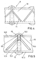
- Figures 4 and 5 represent the join (8) in a preferred embodiment in which a horizontal "U" shaped reinforcement section (10) has been taken with the "L" shaped sections (11) taken as vertical elements.
- the section (10) has two holes drilled in it (10.1) in the wings (10.2) through which a screw (12) passes.
- the outer faces of the wings (10.2) have concentric circular grooves (10.3) cut to house the heads of the nuts (14) and screws (13) thus protecting them.
- the screw (12) has a body in two sections, a stud (12.1) and the end of smaller diameter (12.2) threaded with a step (12.3) to separate the two.
- the end (12.2) of the screw (12) passes through the "L" shaped section (11) via a hole of its diameter.
- the step (12.3) presses against the section (11) improving its fixing to the horizontal section (10).
- the threaded end (12.2) of the screw goes to a nut (13) that holds the assembly together.
- Figure 6 represents another preferred embodiment of the invention in which the vertical element (14) is a square section
- the section (14) has two holes of different diameters, the first to allow the stud (12.1) to pass and the second to allow the threaded end (12.2) to pass.
- Figures (7) and (8) show the two variants for joining bars for the construction of seals that are of elevated height.
- Figure (7) shows two bars (6) joined at their ends by a horizontal reinforcing billet (5).
- An end of the bar has a coaxial threaded stud (6.4) that enters the threaded hole (6.3) from the other end of the coaxial bar.
- the billet (5) has a hole (5.7) with the same diameter as that of the stud such that this allows this to screw into the other bar so that the billet (5) is fixed between the two bars.
- the scheme followed in figure (8) shows a perimeter groove (6.5) in both bars that allows these bars to partially enter into the hole (5.8) of the billet, which has a greater diameter than that of the stud and less than that of the bar.
- the billet (5) is similarly fixed between the bars (6) with the additional advantage that the billet (5) does not damage the thread of the stud (6.4) as its transversal displacement is impeded.
- the threaded stud is protected in the billet.
- Figure 9 shows a theoretical configuration of the seal in which different solutions have been incorporated into the joins for its construction.
Landscapes
- Engineering & Computer Science (AREA)
- Architecture (AREA)
- Structural Engineering (AREA)
- Civil Engineering (AREA)
- Joining Of Building Structures In Genera (AREA)
- Fencing (AREA)
- Orthopedics, Nursing, And Contraception (AREA)
- Gasket Seals (AREA)
- External Artificial Organs (AREA)
- Massaging Devices (AREA)
Abstract
Description
- The invention herein put forward consists of a procedure of modular construction in order to obtain seals based on joins between vertical and horizontal elements.
- This invention characterises the joining procedures used in the modular construction based on the use of breakable screws in billets, bars and sections.
- The different constitutive elements are linked to one another by means for joining placed at the ends of the bars of vertical elements and the billets.
- Equally, they characterise means for joining between vertical elements for the construction of seals of great length with horizontal reinforcements.
- Similarly, they characterise means for joining between horizontal reinforcement sections with the vertical elements at points not at the end of open and closed sections.
- Grills and modular fencing from the same applicant are the object of the Model 1034506U and the international patent of application number 9701116 and their certificates of addition, of application numbers 9702195 and 9800617.
- In all of these the modular construction is claimed, both of windows and fences, and also a series of means and devices is described for linking the rails to the billets, as well as linking these to the wall of the frame in the case of windows.
- Equally, from the same applicant, patents ES9800095 and ES9900192 claim a grill with elements that can be assembled and means for joining of a different nature.
- The object of the present invention consists of a set of solutions for joining different sections, billets and bars that constitute the seal for application in DIY.
- Just as in the patents mentioned for the background of the invention, the combination of different modules and means for joining allows different final configurations of the seal to be obtained, with the additional advantage of allowing easy transport and assembly.
- By way of example, the grills for windows and fencing have loose components such as horizontal billets, vertical sections of bar or tube form, open vertical sections and closed polygon sections, and means for joining with standardised and normalised measurements so that, by combining these elements, a versatile and safe final product is obtained.
- This invention is characterised by the means of joining the vertical bar or tube type sections with the upper billets.
- It is also characterised by the joins between the vertical and horizontal reinforcement sections used at points not corresponding to the ends in the construction of seals of extended length.
- The solution of using breakable screws is known, in which the hexagonal head is joined to a second rounded head such that when the tightening torque exceeds a certain value in its design, the join breaks and only the rounded head remains joined to the screw.
- The steels used in the screws are not very resistant to allow the hexagonal heads to break at the moment of installation.
- A weak point, with regard to the safety offered by the seal once assembled, is located in the rounded head of the breakable screw.
- It is sufficient to insert a wedge between the head and the outer surface to be able to force and break the head of the screw thus destroying the mechanical join.
- The joins between the upper billets and the lower ones with the ends of the vertical bars or tubes are carried out by means of breakable screws in which the head in the grease ball and the ends of the vertical elements are hidden in mortises in the horizontal billet.
- In the case where bars are used as the vertical section, the threaded end of the breakable screw enters screwed into a hole drilled into the bar, with the centring functions being carried out by a perimeter groove around the end of the bar.
- Both solutions manage to hide the most vulnerable points of the join inside the billet increasing the overall safety offered by the assembly.
- When the vertical element is a tube section with a circular cross-section, the screw with the breakable head screws in because of its greater diameter into the billet leaving the stud as an entrance pivot and support of the vertical tube.
- In the patent E9800095 a join is cited by means of pivot in which this is soldered to the billet. This join is simpler and requires fewer tools for assembly using the breakable screw.
- A third join is considered that can be made between the billet and the vertical section, based on the use of an additional piece that enters into a lower double mortise cut into the billet and which is attached using a breakable screw.
- This additional piece has a cavity on the side opposite to the screw in which the sections or rails of circular or polygonal cross-sections are housed.
- When the seal is very long, the vertical elements should be reinforced to ensure that they do not bend excessively under a certain degree of transversal load.
- Two possible solutions are considered, a first by means of the use of bars of a certain length that can be joined to each other by inserting the horizontal reinforcement elements, and a second that makes use of the vertical elements of greater length and which should be joined to the horizontal reinforcement elements.
- In the first solution, the bars have two ends, one with a threaded stud and the other with a threaded hole.
- In this fashion it is possible to connect the bars necessary until a desired length is reached.
- The length of the stud is sufficient to allow a billet to be inserted between bars as an element of horizontal reinforcement.
- A first variant makes use of a hole that allows the threaded stud to screw in with the billet inserted and pressed against the two bars of larger diameter.
- The second variant consists of choosing the diameter of the hole of the billet of intermediate size between the diameter of the stud and the diameter of the bar.
- The bar has a perimeter groove at both ends with a thickness less than half the thickness of the billet such that the billet is equally pressed between the two bars.
- In this situation, the stud is not in contact with the billet, and the bars are not in contact between themselves except by means of the studded screw.
- The second solution makes use of the vertical elements running along the length of the seal. It is necessary to use horizontal reinforcement elements.
- The invention contemplates the means of joining between the vertical elements and the horizontal elements.
- The proposed solution is valid for sections of open and closed vertical cross-sections, taking from all the possible configurations two preferred embodiments for a clear description, one open in an "L" shape and the other closed with a square cross-section.
- The section chosen in the horizontal reinforcement element of the preferred embodiments is a "U"-shaped section.
- On the core of the horizontal reinforcement sections holes are drilled with the profile of the vertical element that passes through it.
- In the preferred embodiment in which the horizontal section is in the form of a "U", the section has two coaxial holes in the wings through which a breakable screw passes composed of a stud with an end with a perimeter groove and with a thread.
- Both the head of the screw and the nut are housed in mortises exterior to the wings of the horizontal section to avoid being destroyed in the same way as the cases already discussed.
- The vertical element has a hole in it if it has an open profile and two if it is closed at the level where the horizontal reinforcement is to be placed. The aforementioned screw passes through this/these hole(s).
- The screw is fixed by means of a ball head nut at the other end of the horizontal section.
- In the preferred embodiment in which the section of the vertical element is in the form of an "L", the screw enters the open side of the "L", pressing against the vertical element by means of a stepping present between the stud and the threaded end against the opposite wing of the horizontal section.
- Another preferred embodiment considers a square section of the vertical element with a diagonal parallel to the longitudinal axis of the horizontal reinforcement section.
- In this other embodiment, the tube requires two holes to allow the screw to pass.
- The hole nearest to the screw will have a diameter that will allow the stud to clear while the opposite hole will have a small diameter to allow the threaded stud to pass and not the previous one.
- In this fashion, the stepping present between the threaded stud and the non-threaded stud will press the vertical element against the horizontal section thus increasing the rigidity of the assembly and avoiding play due to possible looseness.
- To complete the description that is being carried out here and with the aim of assisting in a better understanding of the characteristics of the invention, the present specification is accompanied, as an integral part thereof, by a set of plans in which, by way of illustration and in non-limiting fashion, the following has been represented:
- Figure 1: Represents a join for seals between the upper or lower billet and the vertical bar.
- Figure 2: Represents a join for seals between the upper or lower billet and a vertical tube.
- Figure 3: Represents a join for seals between the upper or lower billet and vertical element by means of an additional piece.
- Figure 4: Represents the arrangement of two consecutive joins between horizontal reinforcement section and vertical sections in a seal.
- Figure 5: Represents the join between the horizontal reinforcement section and the vertical element with an "L" shaped cross-section in a preferred embodiment of the seal.
- Figure 6: Represents the join between the horizontal reinforcement section and the vertical element with square shaped cross-section in another preferred embodiment of the seal.
- Figure 7: Represents a join between vertical elements with reinforcement billet.
- Figure 8: Represents a second variation of joining between vertical elements with reinforcement billet.
- Figure 9: Represents a theoretical composition in which the different solutions are combined for a seal of modular construction.
-
- In view of the aforementioned figures the different procedures for forming joins between billets and bars or tubes of the different preferred embodiments are now described both at the upper and lower end and at intermediate reinforcement points.
- The joins (1), (2) and (3) between the billet (5) and the different types of vertical element (6) of bar or tube type are described.
- Figure 1 shows the join (1) in which the billet (5) is linked to the vertical bar (6).
- The upper billet (5) has a hole with an upper double mortise [(5.1) and (5.2)] and a mortise step (5.3).
- The upper mortise (5.2) allows the central body (4.1) of a screw (4) with a breakable head to be centred.
- The screw (4) is housed in the rounded head in the second mortise (5.1) of larger diameter, and is thus protected.
- From the screw (4) a threaded stud (4.2) sticks out downwards and enters into a hole (6.1), also threaded, which has been drilled in the bar (6).
- The bar (6) has an end perimeter groove (6.2) that enters in the groove (5.3) thus hiding the join surface.
- Figure 2 shows the join (2) between the billet (5) and a tube (6) by means of a breakable screw (4) with a thread in its middle part (4.2) in the mortise (5.4) such that once tightened, the screw (4) sticks out on the other side of the billet (5) in a pivot (4.3) that enters in the hollow of the tube (6).
- The head of the screw (4) is also hidden in the mortise (5.1) in this procedure (2) for joining.
- The end of the tube (6) is housed in the groove (5.3), being hidden inside the billet (5).
- Figure 3 shows the join (3) between a vertical element with a circular or polygonal cross-section (6) and the billet (5) by means of an auxiliary piece (7).
- In this preferred embodiment, the breakable screw (4) consists only of a short threaded stud (4.4) that screws into the auxiliary piece (7).
- The auxiliary piece (7) enters into a lower double mortise (5.5) and (5.6) of the billet (5) and is fixed by means of the screw (4).
- The upper mortise (5.1) also hides the screw head (6).
- The auxiliary piece (7) has a lower mortise (7.1) which is what houses the vertical element (6).
- The lower parts of figures 1, 2 and 3 show the finished assembly of each of the joins herein described.
- Figures 4 and 5 represent the join (8) in a preferred embodiment in which a horizontal "U" shaped reinforcement section (10) has been taken with the "L" shaped sections (11) taken as vertical elements.
- The section (10) has two holes drilled in it (10.1) in the wings (10.2) through which a screw (12) passes.
- The outer faces of the wings (10.2) have concentric circular grooves (10.3) cut to house the heads of the nuts (14) and screws (13) thus protecting them.
- The screw (12) has a body in two sections, a stud (12.1) and the end of smaller diameter (12.2) threaded with a step (12.3) to separate the two.
- The end (12.2) of the screw (12) passes through the "L" shaped section (11) via a hole of its diameter.
- The step (12.3) presses against the section (11) improving its fixing to the horizontal section (10).
- The threaded end (12.2) of the screw goes to a nut (13) that holds the assembly together.
- Figure 6 represents another preferred embodiment of the invention in which the vertical element (14) is a square section
- In this embodiment the section (14) has two holes of different diameters, the first to allow the stud (12.1) to pass and the second to allow the threaded end (12.2) to pass.
- In this fashion the stepping (12.3) is within the section (14) pressing against the wing (10.2) of the side of the nut (13).
- Figures (7) and (8) show the two variants for joining bars for the construction of seals that are of elevated height.
- Figure (7) shows two bars (6) joined at their ends by a horizontal reinforcing billet (5).
- An end of the bar has a coaxial threaded stud (6.4) that enters the threaded hole (6.3) from the other end of the coaxial bar.
- The billet (5) has a hole (5.7) with the same diameter as that of the stud such that this allows this to screw into the other bar so that the billet (5) is fixed between the two bars.
- The scheme followed in figure (8) shows a perimeter groove (6.5) in both bars that allows these bars to partially enter into the hole (5.8) of the billet, which has a greater diameter than that of the stud and less than that of the bar.
- The billet (5) is similarly fixed between the bars (6) with the additional advantage that the billet (5) does not damage the thread of the stud (6.4) as its transversal displacement is impeded.
- In any of the two variants, the threaded stud is protected in the billet.
- Figure 9 shows a theoretical configuration of the seal in which different solutions have been incorporated into the joins for its construction.
Claims (8)
- A procedure for the construction of seals for DIY characterised in that the seal consists of:horizontal bars (5) that are arranged above and below the seal and which connect with the vertical element (6),vertical elements (6) consisting of bars, tubes or sections, that connect the upper and lower billets (5),horizontal elements consisting of reinforcement billets (5) or sections (10),means for joining the vertical elements (6), (11) and (14); to the reinforcement horizontal elements (5) and (10).
- A procedure for the construction of seals for DIY according to the first claim characterised in that the join (1) between the billet (5) and the bar (6) is carried out by means of the breakable screw (4) consisting of a central body (4.1) of greater diameter than the threaded stud (4.2), with the central body housed in the mortise (5.2) and the head of the screw (4) in a second upper mortise (5.1); the threaded stud (4.2) enters in the threaded hole (6.1) of the end of the bar (6) over which there is a perimeter groove (6.2) that fits into the lower mortise (5.3) of the protection billet (5).
- A procedure for the construction of seals for DIY according to the first claim characterised in that the join (2) between the billet (5) and the tube (6) is carried out by means of the breakable screw (4) consisting of a central body (4.2) screwed into the mortise (5.4), of larger diameter than the stud (4.3) that is housed inside the tube (6), with a second upper mortise (5.1) to house the head of the screw, and a third lower mortise (5.3) of the billet (5) in which the end of the tube is housed (6).
- A procedure for the construction of seals for DIY according to the first claim characterised in that the join (3) between the billet (5) and the bar (6) is carried out by means of the breakable screw (4) consisting of a threaded stud (4.4) that screws into an auxiliary piece (7) inserted into the opposite side of the billet (5) housed in the double mortise (5.5) and (5.6) with the head of the screw (4) housed in an upper mortise (5.1); the additional piece has a lower mortise (7.1) in which the vertical element (6) is housed.
- A procedure for the construction of seals for DIY according to the first claim characterised in that the join (8) between the vertical elements of open cross-section (11) and the horizontal reinforcement section (10) is carried out by means of a breakable passing screw (12) that constitutes a first stud (12.1) near to the head and a second threaded stud (12.2) of a smaller diameter than the second that gives rise to a stepping (12.3) that ensures the join with the horizontal section (15) by pressing the stepping (12.3) against the face oriented towards the head of the screw (12) of the vertical element (11), both the head of the screw (12) and the nut (13) are found housed in the mortise (10.3).
- A procedure for the construction of seals for DIY according to the first claim characterised in that the join (9) between the vertical elements of closed cross-section (14) and the horizontal reinforcement section (10) is carried out by means of a breakable passing screw (12) that has a first stud (12.1) near to the head and a second threaded stud (12.2) of smaller diameter than the second that gives rise to a stepping (12.3) that ensures the join with the horizontal section horizontal section (10) by pressing the stepping (12.3) against the inner face oriented towards the head of the screw (12) of the vertical element (14), both the head of the screw (12) and the nut (13) are found housed in the mortise (10.3).
- A procedure for the construction of seals for DIY according to the first claim characterised in that the join (15) between the joinable vertical elements (6) and the horizontal reinforcement billet (5) is carried out by means of a threaded stud (6.4) located at the end of the vertical element (6) that screws into the threaded hole (6.3) at the other end of the other bar (6), passing through a hole (5.7) of the billet (5) such that this is inserted and pressed against both bars (6).
- A procedure for the construction of seals for DIY according to the first claim characterised in that the join (15) between the joinable vertical elements (6) and the horizontal reinforcement billet (5) is carried out by means of a threaded stud (6.4). located at the end of the vertical element (6) that screws into the threaded hole (6.3) at the other end of the other bar (6) that screws into the threaded hole (6.3) at the other end of the other bar (6), passing through a hole (5.7) of the billet (5) of a diameter equal to that of the perimeter grooves (6.5) of the ends of the bars (6) and with a length of perimeter groove (6.5) less than half the thickness of the billet (5) such that the billet (5) is inserted and pressed against both bars (6) without the possibility of contact between the billet (5) and the threaded stud (6.4).
Applications Claiming Priority (1)
| Application Number | Priority Date | Filing Date | Title |
|---|---|---|---|
| PCT/ES2000/000287 WO2002012658A1 (en) | 2000-07-28 | 2000-07-28 | Do-it-yourself assembly method |
Publications (2)
| Publication Number | Publication Date |
|---|---|
| EP1306500A1 true EP1306500A1 (en) | 2003-05-02 |
| EP1306500B1 EP1306500B1 (en) | 2008-04-16 |
Family
ID=8244254
Family Applications (1)
| Application Number | Title | Priority Date | Filing Date |
|---|---|---|---|
| EP00951531A Expired - Lifetime EP1306500B1 (en) | 2000-07-28 | 2000-07-28 | Do-it-yourself assembly method |
Country Status (6)
| Country | Link |
|---|---|
| EP (1) | EP1306500B1 (en) |
| AT (1) | ATE392522T1 (en) |
| DE (1) | DE60038633D1 (en) |
| ES (1) | ES2303817T3 (en) |
| PT (1) | PT1306500E (en) |
| WO (1) | WO2002012658A1 (en) |
Cited By (4)
| Publication number | Priority date | Publication date | Assignee | Title |
|---|---|---|---|---|
| EP1512812A1 (en) * | 2003-09-08 | 2005-03-09 | Patrice Hureau | Custom made fence |
| FR2859519A1 (en) * | 2003-09-08 | 2005-03-11 | Patrice Hureau | Protection/decorative grill for e.g. balcony, has connecting units with bulge sections stopping against crosspieces when rod is introduced into passage, where rod has length greater than thickness of crosspieces to protrude from crosspieces |
| CN105908659A (en) * | 2016-04-26 | 2016-08-31 | 杜玲玲 | Road isolation fence |
| CN108316837A (en) * | 2018-01-24 | 2018-07-24 | 李堂波 | A kind of invisible anti-theft network facilitating installation |
Families Citing this family (1)
| Publication number | Priority date | Publication date | Assignee | Title |
|---|---|---|---|---|
| TWI689660B (en) | 2019-03-21 | 2020-04-01 | 劉子瑄 | Reinforced extrusion device capable of rapid assembly |
Family Cites Families (6)
| Publication number | Priority date | Publication date | Assignee | Title |
|---|---|---|---|---|
| DE2733498A1 (en) * | 1977-07-25 | 1979-02-08 | Jens Dethloff | FENCE OF LARGE-AREA FENCE ELEMENTS FIXED TO POST |
| FR2560651B3 (en) * | 1984-03-01 | 1986-02-28 | Orsogril Spa | SAFETY CLOSING DEVICE |
| ES1016728Y (en) * | 1991-01-30 | 1992-06-01 | Bizcocho Hermanos, S.L. | DEVICE FOR FIXING WIRING FENCES TO ANCHORAGE PROPS. |
| PL331255A1 (en) * | 1997-05-23 | 1999-07-05 | Bizcocho Hermanos | Grating for mounting on window openings, as a part of fencing and for similar purposes |
| ES1037833Y (en) * | 1997-07-14 | 1998-11-01 | Franco Reula Ana Carmen | PILLARS FOR ENCLOSURES. |
| EP1033468A1 (en) * | 1998-06-29 | 2000-09-06 | Bizcocho Hermanos, S.L. | Process for fabricating gratings for windows, fences and the like |
-
2000
- 2000-07-28 EP EP00951531A patent/EP1306500B1/en not_active Expired - Lifetime
- 2000-07-28 WO PCT/ES2000/000287 patent/WO2002012658A1/en not_active Ceased
- 2000-07-28 ES ES00951531T patent/ES2303817T3/en not_active Expired - Lifetime
- 2000-07-28 PT PT00951531T patent/PT1306500E/en unknown
- 2000-07-28 DE DE60038633T patent/DE60038633D1/en not_active Expired - Lifetime
- 2000-07-28 AT AT00951531T patent/ATE392522T1/en not_active IP Right Cessation
Non-Patent Citations (1)
| Title |
|---|
| See references of WO0212658A1 * |
Cited By (6)
| Publication number | Priority date | Publication date | Assignee | Title |
|---|---|---|---|---|
| EP1512812A1 (en) * | 2003-09-08 | 2005-03-09 | Patrice Hureau | Custom made fence |
| FR2859520A1 (en) * | 2003-09-08 | 2005-03-11 | Patrice Hureau | GRID ON MESURE. |
| FR2859519A1 (en) * | 2003-09-08 | 2005-03-11 | Patrice Hureau | Protection/decorative grill for e.g. balcony, has connecting units with bulge sections stopping against crosspieces when rod is introduced into passage, where rod has length greater than thickness of crosspieces to protrude from crosspieces |
| CN105908659A (en) * | 2016-04-26 | 2016-08-31 | 杜玲玲 | Road isolation fence |
| CN108316837A (en) * | 2018-01-24 | 2018-07-24 | 李堂波 | A kind of invisible anti-theft network facilitating installation |
| CN108316837B (en) * | 2018-01-24 | 2020-04-07 | 李堂波 | Invisible anti-theft net convenient to install |
Also Published As
| Publication number | Publication date |
|---|---|
| DE60038633D1 (en) | 2008-05-29 |
| EP1306500B1 (en) | 2008-04-16 |
| PT1306500E (en) | 2008-06-18 |
| WO2002012658A1 (en) | 2002-02-14 |
| ES2303817T3 (en) | 2008-09-01 |
| ATE392522T1 (en) | 2008-05-15 |
Similar Documents
| Publication | Publication Date | Title |
|---|---|---|
| EP0784126B1 (en) | Skeleton structure made of profiled members | |
| DE2707704A1 (en) | METAL RAILING | |
| EP1306500B1 (en) | Do-it-yourself assembly method | |
| DE4333029C2 (en) | Structure made of bamboo tubes | |
| DE3438773C2 (en) | ||
| DE19828189C1 (en) | Mullion-transom connection | |
| DE10012690C1 (en) | Connector for upright and cross member of fireproof frame construction has inlaid element made from adequately temperature resistant material in case of fire, and temperature non-resistant support element enclosing it | |
| CA2414416A1 (en) | Gate or door frame assembly and method of making a gate or door | |
| CH668105A5 (en) | CONNECTION ARRANGEMENT FOR AT LEAST ONE LONG PROFILE WITH ANOTHER BODY TO BE CONNECTED TO IT. | |
| DE102007001830A1 (en) | Tension or compression bar for low voltage system, has inner rod extending in longitudinal direction, and outer rod connected with hollow space extending in longitudinal direction, where inner rod is arranged at hollow space | |
| CH697039A5 (en) | Profile frame structure comprises a wooden base structure and a base profile fastened to the base structure by nails oriented at an angle to the middle plane of the base structure | |
| DE3539507A1 (en) | Scaffolding frame board | |
| EP0955420B1 (en) | Façade profile | |
| EP2581523A2 (en) | Frame anchor with frame support for heat insulation compound systems | |
| DE4344344C2 (en) | Chimney with several chimney elements which are rigidly connected to one another by connecting arrangements | |
| EP0860560B1 (en) | Connector for butt joining two elements, specially in wooden structures | |
| EP1548200B1 (en) | Mullion and transom facade | |
| DE4018003A1 (en) | Thermally insulated composite sections - consists of inner and outer section joined and held apart by rails with bolts | |
| DE102020106891B4 (en) | T-connection between a mullion and transom profile and a mullion-transom construction with such a T-connection | |
| DE10349791A1 (en) | Method for assembling a support frame especially for a facade has connecting elements which grip the uprights and horizontals with a minimum of reduction in the strength of the supports | |
| DE102006001045B4 (en) | Corner connector for door or window frame | |
| DE29603402U1 (en) | Framework with angle or corner connections of metal profiles, in particular made of light metal | |
| DE102004045736A1 (en) | Connection device for hollow profile lengths uses triangular profile fastened to one hollow profile side, with undercut longitudinal grooves to hold connection screws | |
| DE3328232A1 (en) | Three-dimensional framework | |
| DE102024100923A1 (en) | Coupling device for building facades or windows |
Legal Events
| Date | Code | Title | Description |
|---|---|---|---|
| PUAI | Public reference made under article 153(3) epc to a published international application that has entered the european phase |
Free format text: ORIGINAL CODE: 0009012 |
|
| 17P | Request for examination filed |
Effective date: 20021223 |
|
| AK | Designated contracting states |
Designated state(s): AT BE CH CY DE DK ES FI FR GB GR IE IT LI LU MC NL PT SE |
|
| 17Q | First examination report despatched |
Effective date: 20070613 |
|
| GRAP | Despatch of communication of intention to grant a patent |
Free format text: ORIGINAL CODE: EPIDOSNIGR1 |
|
| GRAS | Grant fee paid |
Free format text: ORIGINAL CODE: EPIDOSNIGR3 |
|
| GRAA | (expected) grant |
Free format text: ORIGINAL CODE: 0009210 |
|
| AK | Designated contracting states |
Kind code of ref document: B1 Designated state(s): AT BE CH CY DE DK ES FI FR GB GR IE IT LI LU MC NL PT SE |
|
| REG | Reference to a national code |
Ref country code: CH Ref legal event code: EP |
|
| REG | Reference to a national code |
Ref country code: IE Ref legal event code: FG4D |
|
| REF | Corresponds to: |
Ref document number: 60038633 Country of ref document: DE Date of ref document: 20080529 Kind code of ref document: P |
|
| REG | Reference to a national code |
Ref country code: PT Ref legal event code: SC4A Free format text: AVAILABILITY OF NATIONAL TRANSLATION Effective date: 20080605 |
|
| REG | Reference to a national code |
Ref country code: ES Ref legal event code: FG2A Ref document number: 2303817 Country of ref document: ES Kind code of ref document: T3 |
|
| NLV1 | Nl: lapsed or annulled due to failure to fulfill the requirements of art. 29p and 29m of the patents act | ||
| PG25 | Lapsed in a contracting state [announced via postgrant information from national office to epo] |
Ref country code: NL Free format text: LAPSE BECAUSE OF FAILURE TO SUBMIT A TRANSLATION OF THE DESCRIPTION OR TO PAY THE FEE WITHIN THE PRESCRIBED TIME-LIMIT Effective date: 20080416 Ref country code: FI Free format text: LAPSE BECAUSE OF FAILURE TO SUBMIT A TRANSLATION OF THE DESCRIPTION OR TO PAY THE FEE WITHIN THE PRESCRIBED TIME-LIMIT Effective date: 20080416 |
|
| PG25 | Lapsed in a contracting state [announced via postgrant information from national office to epo] |
Ref country code: AT Free format text: LAPSE BECAUSE OF FAILURE TO SUBMIT A TRANSLATION OF THE DESCRIPTION OR TO PAY THE FEE WITHIN THE PRESCRIBED TIME-LIMIT Effective date: 20080416 |
|
| PG25 | Lapsed in a contracting state [announced via postgrant information from national office to epo] |
Ref country code: DE Free format text: LAPSE BECAUSE OF FAILURE TO SUBMIT A TRANSLATION OF THE DESCRIPTION OR TO PAY THE FEE WITHIN THE PRESCRIBED TIME-LIMIT Effective date: 20080717 Ref country code: SE Free format text: LAPSE BECAUSE OF FAILURE TO SUBMIT A TRANSLATION OF THE DESCRIPTION OR TO PAY THE FEE WITHIN THE PRESCRIBED TIME-LIMIT Effective date: 20080716 Ref country code: DK Free format text: LAPSE BECAUSE OF FAILURE TO SUBMIT A TRANSLATION OF THE DESCRIPTION OR TO PAY THE FEE WITHIN THE PRESCRIBED TIME-LIMIT Effective date: 20080416 |
|
| PLBE | No opposition filed within time limit |
Free format text: ORIGINAL CODE: 0009261 |
|
| STAA | Information on the status of an ep patent application or granted ep patent |
Free format text: STATUS: NO OPPOSITION FILED WITHIN TIME LIMIT |
|
| EN | Fr: translation not filed | ||
| PG25 | Lapsed in a contracting state [announced via postgrant information from national office to epo] |
Ref country code: BE Free format text: LAPSE BECAUSE OF FAILURE TO SUBMIT A TRANSLATION OF THE DESCRIPTION OR TO PAY THE FEE WITHIN THE PRESCRIBED TIME-LIMIT Effective date: 20080416 |
|
| REG | Reference to a national code |
Ref country code: CH Ref legal event code: PL |
|
| 26N | No opposition filed |
Effective date: 20090119 |
|
| GBPC | Gb: european patent ceased through non-payment of renewal fee |
Effective date: 20080728 |
|
| PG25 | Lapsed in a contracting state [announced via postgrant information from national office to epo] |
Ref country code: MC Free format text: LAPSE BECAUSE OF NON-PAYMENT OF DUE FEES Effective date: 20080731 |
|
| PG25 | Lapsed in a contracting state [announced via postgrant information from national office to epo] |
Ref country code: LI Free format text: LAPSE BECAUSE OF NON-PAYMENT OF DUE FEES Effective date: 20080731 Ref country code: CH Free format text: LAPSE BECAUSE OF NON-PAYMENT OF DUE FEES Effective date: 20080731 Ref country code: GB Free format text: LAPSE BECAUSE OF NON-PAYMENT OF DUE FEES Effective date: 20080728 |
|
| PG25 | Lapsed in a contracting state [announced via postgrant information from national office to epo] |
Ref country code: IE Free format text: LAPSE BECAUSE OF NON-PAYMENT OF DUE FEES Effective date: 20080728 |
|
| PG25 | Lapsed in a contracting state [announced via postgrant information from national office to epo] |
Ref country code: IT Free format text: LAPSE BECAUSE OF FAILURE TO SUBMIT A TRANSLATION OF THE DESCRIPTION OR TO PAY THE FEE WITHIN THE PRESCRIBED TIME-LIMIT Effective date: 20080416 |
|
| PG25 | Lapsed in a contracting state [announced via postgrant information from national office to epo] |
Ref country code: CY Free format text: LAPSE BECAUSE OF FAILURE TO SUBMIT A TRANSLATION OF THE DESCRIPTION OR TO PAY THE FEE WITHIN THE PRESCRIBED TIME-LIMIT Effective date: 20080416 |
|
| PGFP | Annual fee paid to national office [announced via postgrant information from national office to epo] |
Ref country code: ES Payment date: 20090810 Year of fee payment: 10 |
|
| PGFP | Annual fee paid to national office [announced via postgrant information from national office to epo] |
Ref country code: PT Payment date: 20090720 Year of fee payment: 10 |
|
| PG25 | Lapsed in a contracting state [announced via postgrant information from national office to epo] |
Ref country code: LU Free format text: LAPSE BECAUSE OF NON-PAYMENT OF DUE FEES Effective date: 20080728 |
|
| PG25 | Lapsed in a contracting state [announced via postgrant information from national office to epo] |
Ref country code: GR Free format text: LAPSE BECAUSE OF FAILURE TO SUBMIT A TRANSLATION OF THE DESCRIPTION OR TO PAY THE FEE WITHIN THE PRESCRIBED TIME-LIMIT Effective date: 20080717 |
|
| REG | Reference to a national code |
Ref country code: PT Ref legal event code: MM4A Free format text: LAPSE DUE TO NON-PAYMENT OF FEES Effective date: 20110128 |
|
| PG25 | Lapsed in a contracting state [announced via postgrant information from national office to epo] |
Ref country code: PT Free format text: LAPSE BECAUSE OF NON-PAYMENT OF DUE FEES Effective date: 20110128 |
|
| REG | Reference to a national code |
Ref country code: ES Ref legal event code: FD2A Effective date: 20110818 |
|
| PG25 | Lapsed in a contracting state [announced via postgrant information from national office to epo] |
Ref country code: ES Free format text: LAPSE BECAUSE OF NON-PAYMENT OF DUE FEES Effective date: 20100729 |
|
| PG25 | Lapsed in a contracting state [announced via postgrant information from national office to epo] |
Ref country code: FR Free format text: LAPSE BECAUSE OF FAILURE TO SUBMIT A TRANSLATION OF THE DESCRIPTION OR TO PAY THE FEE WITHIN THE PRESCRIBED TIME-LIMIT Effective date: 20090227 |