EP1306343A2 - Mobile crane vehicle including a movable range indicating apparatus - Google Patents
Mobile crane vehicle including a movable range indicating apparatus Download PDFInfo
- Publication number
- EP1306343A2 EP1306343A2 EP03090012A EP03090012A EP1306343A2 EP 1306343 A2 EP1306343 A2 EP 1306343A2 EP 03090012 A EP03090012 A EP 03090012A EP 03090012 A EP03090012 A EP 03090012A EP 1306343 A2 EP1306343 A2 EP 1306343A2
- Authority
- EP
- European Patent Office
- Prior art keywords
- operating radius
- movable range
- boom
- detecting means
- detecting
- Prior art date
- Legal status (The legal status is an assumption and is not a legal conclusion. Google has not performed a legal analysis and makes no representation as to the accuracy of the status listed.)
- Withdrawn
Links
Images


Classifications
-
- B—PERFORMING OPERATIONS; TRANSPORTING
- B66—HOISTING; LIFTING; HAULING
- B66C—CRANES; LOAD-ENGAGING ELEMENTS OR DEVICES FOR CRANES, CAPSTANS, WINCHES, OR TACKLES
- B66C13/00—Other constructional features or details
- B66C13/16—Applications of indicating, registering, or weighing devices
-
- B—PERFORMING OPERATIONS; TRANSPORTING
- B66—HOISTING; LIFTING; HAULING
- B66C—CRANES; LOAD-ENGAGING ELEMENTS OR DEVICES FOR CRANES, CAPSTANS, WINCHES, OR TACKLES
- B66C23/00—Cranes comprising essentially a beam, boom, or triangular structure acting as a cantilever and mounted for translatory of swinging movements in vertical or horizontal planes or a combination of such movements, e.g. jib-cranes, derricks, tower cranes
- B66C23/88—Safety gear
- B66C23/90—Devices for indicating or limiting lifting moment
- B66C23/905—Devices for indicating or limiting lifting moment electrical
-
- B—PERFORMING OPERATIONS; TRANSPORTING
- B66—HOISTING; LIFTING; HAULING
- B66C—CRANES; LOAD-ENGAGING ELEMENTS OR DEVICES FOR CRANES, CAPSTANS, WINCHES, OR TACKLES
- B66C23/00—Cranes comprising essentially a beam, boom, or triangular structure acting as a cantilever and mounted for translatory of swinging movements in vertical or horizontal planes or a combination of such movements, e.g. jib-cranes, derricks, tower cranes
- B66C23/62—Constructional features or details
- B66C23/64—Jibs
- B66C23/70—Jibs constructed of sections adapted to be assembled to form jibs or various lengths
- B66C23/701—Jibs constructed of sections adapted to be assembled to form jibs or various lengths telescopic
-
- B—PERFORMING OPERATIONS; TRANSPORTING
- B66—HOISTING; LIFTING; HAULING
- B66C—CRANES; LOAD-ENGAGING ELEMENTS OR DEVICES FOR CRANES, CAPSTANS, WINCHES, OR TACKLES
- B66C2700/00—Cranes
- B66C2700/03—Cranes with arms or jibs; Multiple cranes
- B66C2700/0321—Travelling cranes
- B66C2700/0357—Cranes on road or off-road vehicles, on trailers or towed vehicles; Cranes on wheels or crane-trucks
- B66C2700/0364—Cranes on road or off-road vehicles, on trailers or towed vehicles; Cranes on wheels or crane-trucks with a slewing arm
- B66C2700/0371—Cranes on road or off-road vehicles, on trailers or towed vehicles; Cranes on wheels or crane-trucks with a slewing arm on a turntable
Definitions
- the present invention relates to a mobile crane vehicle including a movable range indicating apparatus, and more particularly, to a movable range indicating apparatus for a telescopic boom end of a mobile crane vehicle.
- mobile cranes have included a revolving super structure provided on a self-movable base carrier, and a telescopic boom which extends and contracts in a plurality of stages has been mounted to the revolving super structure.
- a hook is drooped from the end of the telescopic boom through a wire, and a crane operation is performed using the hook.
- an operator is required to grasp a condition of the telescopic boom at all times.
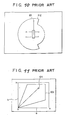
- conventional movable range indicating apparatuses for mobile crane vehicles, etc. adopt polar coordinates in which a radial direction is taken as an operating radius or a load factor, and a circumferential direction is taken as a turning angle (refer to, for example, Japanese Examined Patent Publication No. 317759, Japanese Unexamined Patent Publication No. 3-67895, and Japanese Unexamined Utility Model Publication No. 3130291).
- a rated operating radius corresponding to a current actual lifting load is calculated for each turning angle so as to be taken as the actual operating radius.
- a telescopic boom end position 61 obtained from the actual operating radius and the actual turning position, and a rated operating radius 62 (limit movable range) for each turning angle are indicated by images by superposition.
- most of the conventional apparatuses have an operation range limit function of moving the telescopic boom of the mobile crane vehicle to a desired position in advance to set the movable range, and of sounding an alarm and of limiting the action of the telescopic boom when the end of the telescopic boom reaches the boundary of the movable range during the operation. For this reason, information about the movable range of the telescopic boom cannot be obtained from the indicating apparatus, and the operator cannot grasp completely the operating radius and the turning range, so that there is a malfunction such that ensuring safety of the operation is hindered.
- an apparatus which subjects a crane to a simulation operation, allows a movable range of a revolving super structure including an operating machine to be stored, and suspends the operation of the crane and gives a warning based on the stored information (refer to, for example, Japanese Unexamined Patent Publication No. 56-75393).
- an indicating apparatus put into practical use (refer to, for example, Japanese Unexamined Patent Publication No. 558589)
- a limit movable range 63 and a telescopic boom end position 64 are indicated by superposition taking the X-coordinate a as the operating radius, and the Y-coordinate as the lift of the telescopic boom.
- the setting is usually performed with a load not being suspended, but the rated operating radius is changed by a lifting load in a load suspending operation. Therefore, even within the limited movable range, the boom may be overloaded depending upon the lifting load. That is, since a region where the boom is overloaded cannot be grasped from the movable range indicated image of the above prior art, there arises a problem in that a suitable advance measure for the prevention of the dangers cannot be taken.
- the present invention has been made to solve the problems of the prior art, and its object is to provide a mobile crane vehicle including a movable range indicating apparatus which can easily and accurately grasp a movable range of a telescopic boom end, and ensure safety of a crane operation.
- a movable range indicating apparatus comprising: a boom length detecting means; a boom angle detecting means; a turning position detecting means; a load detecting means; a movable range setting means; a target point setting means; a display section capable of indicating images in polar coordinates in which the turning angle is taken in the circumferential direction, and the operating radius is taken in the radial direction; and a control section for performing calculation based on signals from each of the means, and for outputting the calculation results to the display section, wherein the control section calculates a current actual operating radius, a current actual load, a rated operating radius for each turning position in a state of suspending the actual load, and a limit operating radius obtained by comparing the rated operating radius with an operating radius limit value set by the movable range setting means, respectively, and wherein the display section indicates the actual operating radius, the limit operating radius and the target point at the
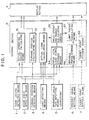
- Fig. 1 illustrates a movable range indicating apparatus which is roughly composed of each of means for performing detection, etc., a control section 8, and a display section 9.
- Each of the means comprise detecting means or inputting means, such as a boom length detecting means 1, a boom angle detecting means 2, a turning position detecting means 3, a load detecting means 4, and an operating condition inputting means (or an operating condition detecting means 5.
- a movable range setting means 6 and/or a target point setting means 7 are included as necessary.
- the above operating condition inputting (or detecting) means 5 is used for setting an operating condition before starting a crane operation, and inputs (or detects) operation modes of a revolving super structure and a base carrier.
- a revolving super structure any one of boom, single top, and jib operations is selected and inputted.
- the boom operation the number of falls of a wire rope for a load suspending hook may be inputted in addition to a normal boom operation.
- the base carrier any one of outrigger, on-tire, and suspending travel operations is selected and inputted.
- an outrigger projecting width is automatically inputted and set by an outrigger length detecting means.
- the above movable range setting means 6 is used for limiting the movable range in the crane operation, and sets the movable range responsive to an obstacle, etc.
- the setting is selected depending on the limitation of any one of crane operations, such as boom angle upper/lower limit, operating radius, boom height, boom length, and turning angle operations, and set by a setting switch.
- the setting method is performed by moving a crane vehicle in advance to an operating position to be controlled, and at the point, by pushing the setting switch corresponding to the operation to be limited. This allows the applicable operational limitation in the crane operation to be stored in a movable range storage means 56 to be described later.
- the movable range setting means includes a means for setting the range one-dimensionally or three-dimensionally.
- the setting of the above target point setting means 7 is performed by moving the crane vehicle to a predetermined operating position, by moving the boom to a target point at that point, and by pushing the setting switch.
- the set items, such as the operating radius and turning position, and a lift of the hook or a lift of the boom as necessary, are stored in a target point storage means 58 to be described later.
- control section 8 comprises an actual operating radius calculating means 51, a turning position calculating means 52, an actual load calculating means 53, a rated total load curve storage means 54, and a rated operating radium calculating means 55. Further, a movable range storage means 56, a limit radius calculating means 57, and/or a target point storage means 58 are included as necessary.
- the actual operating radius calculating means 51 calculates the actual operating radius based on the boom length and the boom angle input from the boom length detecting means 1 and the boom angle detecting means 2.
- the turning position calculating means 52 calculates the turning position from the detected value of the turning position detecting means 3.
- the above actual operating radius and the turning position become an end position of the telescopic boom, and are inputted to the display section 9.
- the actual load calculating means 53 calculates the current actual load based on the boom length, the boom angle, the load, and the operating condition obtained from the boom length detecting means 1, the boom angle detecting means 2, the load detecting means 4, and the operating condition inputting (or detecting) means 5, and outputs the actual load to the rated operating radius calculating means 55.
- the rated total load curve storage means 54 selects the applicable rated total load curve from the previously stored rated total load curves based on the boom length, the turning position, and the operating condition obtained from the boom length detecting means 1, the turning position detecting means 3, and the operating condition inputting (or detecting) means 5, and outputs it to the rated operating radius calculating means 55.
- the rated operating radius calculating means 55 calculates the rated operating radius from the actual load and the rated total load curve, and outputs it to the display section 9.
- the movable range storage means 56 which is included as necessary outputs the movable range (in this embodiment, movable range with respect to the operating radius and the turning angle) set by the movable range setting means 6 to the limit radius calculating means 57.
- the movable range in the turning angle range where turning is impossible, the movable range is outputted as the range having no movable range of the operating radius, i.e., as "0".
- the limit radius calculating means 57 compares the rated operating radius with the movable range for each turning posifion, and outputs a smaller one as the limit radius to the display section 9. That is, the limit radius calculating means 57 obtains an "AND region" between the rated operating radius and the movable range.
- an output from the rated operating radius calculating means 55 to the display section 9 is not performed.
- the rated operating radius from the rated operating radius calculating means 55, and the movable range from the movable range storage means 56 may be outputted to the display section 9 without including (or performing calculation) the limit radius calculating means 57.
- the target point storage means 58 which is included as necessary outputs the target point from the target point setting means 7 to the display section 9.
- Fig. 2 illustrates an example of the movable range indicating apparatus which comprises an operating condition inputting (or detecting) means 5 for inputting (or detecting) operation modes of the revolving super structure and the base carrier, a switch-type movable range setting means 6 for setting a boom length, and boom angle upper limit/lower limits, etc. and a display section 9 of multidisplay.
- a revolving super structure 202 is revolvably provided on a self-movable base carrier 201, and a telescopic boom 204 which is vertically swingable due to a boom cylinder 203 is mounted to the revolving super structure 202.
- the above telescopic boom 204 can extend and contract in a plurality of stages, and a hook 206 is drooped from the tip thereof through a wire 205.
- the telescopic boom 204 is provided with a boom length detecting means 1 for detecting the extension length, and a boom angle detecting means 2 for detecting the angle of the telescopic boom 204, respectively.
- a turning section of the revolving super structure 202 is provided with a turning position detecting means 3
- the boom cylinder 203 is provided with a load detecting means 4
- operating condition inputting (or detecting) means 5 are provided across the base carrier 201, respectively.
- the operating condition inputting (or detecting) means 5 in this embodiment adds a function of detecting a projecting and installation conditions of outriggers to the first embodiment. Incidentally, this addition may be performed to the above second embodiment.
- a movable range setting means 6, and as necessary, a target point setting means 7 are included in addition to the above detecting means 1 to 5.
- Information from these means 1 to 7 is inputted to a control section 8 shown in Fig. 1 to be calculated or stored, and outputted to the display section 9.
- the image is indicated in polar coordinates as described above. Examples of indication of the movable range by the described arrangements will be described.
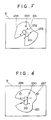
- Fig. 4 is the polar coordinates in which the operating radius is taken in the radial direction and the turning angle is taken in the circumferential direction, and the base carrier 201 which becomes the basis is indicated so as to face upward of the screen at all times.
- Numeral 230 denotes an actual operating radius (and an actual turning position), and
- numeral 231 denotes a limit operating radius with respect to the current load.
- Fig. 5 the revolving super structure 202 which becomes the basis is indicated so as to face upward of the screen at all times.
- Numeral 232 denotes a projecting condition of the outriggers
- numeral 233 denotes an installation condition of the outriggers.
- black dots show a grounding condition and open circles show a floating condition, for example.
- Fig. 6 illustrates a case where target points 236 and 237 are indicated by superposition.
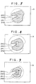
- Figs. 7 to 9 illustrates changes in the movable range when the suspended load is different, in which numeral 240 denotes a turning limit, numeral 241 denotes a rated operating radius due to the current suspended load, and numeral 242 (a diagonally shaded area) denotes a movable range.
- numeral 240 denotes a turning limit
- numeral 241 denotes a rated operating radius due to the current suspended load
- numeral 242 (a diagonally shaded area) denotes a movable range.
- dotted-line areas of the turning limit 240 and the rated operating radius 241 mean limits beyond the movable range 242. Therefore, the operator can easily perform an operation corresponding to the movable range 242, which is changed by the suspended load.
- an interference with an obstacle can be prevented by dealing with it beforehand.
- the present invention is useful as a movable range indicating apparatus for a mobile crane vehicle which enables an accurate and prompt judgement, and which can be easily operated with safety since a telescopic boom end position, a rated operating radius or a predetermined movable range, and a target point as necessary are indicated on the polar coordinates by superposition.
Landscapes
- Engineering & Computer Science (AREA)
- Mechanical Engineering (AREA)
- Jib Cranes (AREA)
Abstract
Description
- The present invention relates to a mobile crane vehicle including a movable range indicating apparatus, and more particularly, to a movable range indicating apparatus for a telescopic boom end of a mobile crane vehicle.
- Hitherto, mobile cranes have included a revolving super structure provided on a self-movable base carrier, and a telescopic boom which extends and contracts in a plurality of stages has been mounted to the revolving super structure. In addition, a hook is drooped from the end of the telescopic boom through a wire, and a crane operation is performed using the hook. When performing the crane operation, an operator is required to grasp a condition of the telescopic boom at all times.
- To this end, conventional movable range indicating apparatuses for mobile crane vehicles, etc., as shown in Fig. 10, adopt polar coordinates in which a radial direction is taken as an operating radius or a load factor, and a circumferential direction is taken as a turning angle (refer to, for example, Japanese Examined Patent Publication No. 317759, Japanese Unexamined Patent Publication No. 3-67895, and Japanese Unexamined Utility Model Publication No. 3130291). According to these apparatuses, a rated operating radius corresponding to a current actual lifting load is calculated for each turning angle so as to be taken as the actual operating radius. In the above polar coordinates, a telescopic
boom end position 61 obtained from the actual operating radius and the actual turning position, and a rated operating radius 62 (limit movable range) for each turning angle are indicated by images by superposition. - Further, most of the conventional apparatuses have an operation range limit function of moving the telescopic boom of the mobile crane vehicle to a desired position in advance to set the movable range, and of sounding an alarm and of limiting the action of the telescopic boom when the end of the telescopic boom reaches the boundary of the movable range during the operation. For this reason, information about the movable range of the telescopic boom cannot be obtained from the indicating apparatus, and the operator cannot grasp completely the operating radius and the turning range, so that there is a malfunction such that ensuring safety of the operation is hindered.
- Next, an apparatus has been known as another prior art which subjects a crane to a simulation operation, allows a movable range of a revolving super structure including an operating machine to be stored, and suspends the operation of the crane and gives a warning based on the stored information (refer to, for example, Japanese Unexamined Patent Publication No. 56-75393). Further, according to an indicating apparatus put into practical use (refer to, for example, Japanese Unexamined Patent Publication No. 558589), as shown in Fig. 11, a limit
movable range 63 and a telescopicboom end position 64 are indicated by superposition taking the X-coordinate a as the operating radius, and the Y-coordinate as the lift of the telescopic boom. - However, when the crane is subjected to the simulation operation by the described arrangement to set the movable range, the setting is usually performed with a load not being suspended, but the rated operating radius is changed by a lifting load in a load suspending operation.
Therefore, even within the limited movable range, the boom may be overloaded depending upon the lifting load. That is, since a region where the boom is overloaded cannot be grasped from the movable range indicated image of the above prior art, there arises a problem in that a suitable advance measure for the prevention of the dangers cannot be taken. - The present invention has been made to solve the problems of the prior art, and its object is to provide a mobile crane vehicle including a movable range indicating apparatus which can easily and accurately grasp a movable range of a telescopic boom end, and ensure safety of a crane operation.
- In the aspect of a mobile crane vehicle including a movable range indicating apparatus according to the present invention, there is provided a movable range indicating apparatus comprising: a boom length detecting means; a boom angle detecting means; a turning position detecting means; a load detecting means; a movable range setting means; a target point setting means; a display section capable of indicating images in polar coordinates in which the turning angle is taken in the circumferential direction, and the operating radius is taken in the radial direction; and a control section for performing calculation based on signals from each of the means, and for outputting the calculation results to the display section,
wherein the control section calculates a current actual operating radius, a current actual load, a rated operating radius for each turning position in a state of suspending the actual load, and a limit operating radius obtained by comparing the rated operating radius with an operating radius limit value set by the movable range setting means, respectively, and
wherein the display section indicates the actual operating radius, the limit operating radius and the target point at the corresponding positions on the polar coordinates by superposition. -
- Fig. 1 is a system block diagram of a movable range indicating apparatus
- Fig. 2 is an external view of the movable range indicating apparatus in which an operating condition inputting (or detecting) means, a movable range setting means, a indicator for detected values from each of the means, and a display section comprising a multidisplay are combined in a single unit;
- Fig. 3 is a side view of a mobile crane vehicle to which a movable range indicating apparatus according to the embodiment of the present invention is applied;
- Fig. 4 is an illustration of a display section according to the embodiment which indicates by superposition a limit operating radius and an actual operating radius on the basis of a base carrier in polar coordinates;
- Fig. 5 is an illustration of the display section in which a revolving super structure is a basis in contrast with Fig. 4;
- Fig. 6 is an illustration of the display section which indicates target points by superposition on Fig. 4;
- Figs. 7 to 9 are drawings which show changes in the movable range with respect to different suspended load, in which Fig. 7 is an illustration of a case where the suspended load is medium;
- Fig. 8 is an illustration of a case where the suspended load is light; and Fig. 9 is an illustration of a case where the suspended load is heavy.
- Fig. 10 is an illustration of an example of indication of a movable range indicating apparatus in polar coordinates according to a prior art; and
- Fig. 11 is an illustration of an example of the indication of a movable range indicating apparatus in rectangular coordinates according to another prior art.
-
- The mobile crane vehicle including a movable range indicating apparatus according to the present invention will be described in detail with reference to the attached drawings.
- Fig. 1 illustrates a movable range indicating apparatus which is roughly composed of each of means for performing detection, etc., a
control section 8, and adisplay section 9. Each of the means comprise detecting means or inputting means, such as a boom length detecting means 1, a boom angle detecting means 2, a turning position detecting means 3, a load detecting means 4, and an operating condition inputting means (or an operating condition detecting means 5. In addition, a movable range setting means 6 and/or a target point setting means 7 are included as necessary. - The above operating condition inputting (or detecting) means 5 is used for setting an operating condition before starting a crane operation, and inputs (or detects) operation modes of a revolving super structure and a base carrier. For example, as regards the revolving super structure, any one of boom, single top, and jib operations is selected and inputted. In the boom operation, the number of falls of a wire rope for a load suspending hook may be inputted in addition to a normal boom operation. On the other hand, as regards the base carrier, any one of outrigger, on-tire, and suspending travel operations is selected and inputted. When selecting the outrigger operation, an outrigger projecting width is automatically inputted and set by an outrigger length detecting means.
- The above movable range setting means 6 is used for limiting the movable range in the crane operation, and sets the movable range responsive to an obstacle, etc. The setting is selected depending on the limitation of any one of crane operations, such as boom angle upper/lower limit, operating radius, boom height, boom length, and turning angle operations, and set by a setting switch. The setting method is performed by moving a crane vehicle in advance to an operating position to be controlled, and at the point, by pushing the setting switch corresponding to the operation to be limited. This allows the applicable operational limitation in the crane operation to be stored in a movable range storage means 56 to be described later. Incidentally, the movable range setting means includes a means for setting the range one-dimensionally or three-dimensionally.
- The setting of the above target point setting means 7 is performed by moving the crane vehicle to a predetermined operating position, by moving the boom to a target point at that point, and by pushing the setting switch. The set items, such as the operating radius and turning position, and a lift of the hook or a lift of the boom as necessary, are stored in a target point storage means 58 to be described later.
- In addition, the
control section 8 comprises an actual operating radius calculating means 51, a turning position calculating means 52, an actual load calculating means 53, a rated total load curve storage means 54, and a rated operating radium calculating means 55. Further, a movable range storage means 56, a limit radius calculating means 57, and/or a target point storage means 58 are included as necessary. - The actual operating radius calculating means 51 calculates the actual operating radius based on the boom length and the boom angle input from the boom length detecting means 1 and the boom angle detecting means 2. In addition, the turning position calculating means 52 calculates the turning position from the detected value of the turning position detecting means 3. The above actual operating radius and the turning position become an end position of the telescopic boom, and are inputted to the
display section 9. The actual load calculating means 53 calculates the current actual load based on the boom length, the boom angle, the load, and the operating condition obtained from the boom length detecting means 1, the boom angle detecting means 2, the load detecting means 4, and the operating condition inputting (or detecting) means 5, and outputs the actual load to the rated operating radius calculating means 55. Further, the rated total load curve storage means 54 selects the applicable rated total load curve from the previously stored rated total load curves based on the boom length, the turning position, and the operating condition obtained from the boom length detecting means 1, the turning position detecting means 3, and the operating condition inputting (or detecting) means 5, and outputs it to the rated operatingradius calculating means 55. The rated operating radius calculating means 55 calculates the rated operating radius from the actual load and the rated total load curve, and outputs it to thedisplay section 9. - The movable range storage means 56 which is included as necessary outputs the movable range (in this embodiment, movable range with respect to the operating radius and the turning angle) set by the movable range setting means 6 to the limit radius calculating means 57. Incidentally, in the turning angle range where turning is impossible, the movable range is outputted as the range having no movable range of the operating radius, i.e., as "0". Next, the limit radius calculating means 57 compares the rated operating radius with the movable range for each turning posifion, and outputs a smaller one as the limit radius to the
display section 9. That is, the limit radius calculating means 57 obtains an "AND region" between the rated operating radius and the movable range. In this case, an output from the rated operating radius calculating means 55 to thedisplay section 9 is not performed. Incidentally, the rated operating radius from the rated operating radius calculating means 55, and the movable range from the movable range storage means 56 may be outputted to thedisplay section 9 without including (or performing calculation) the limit radius calculating means 57. Further, the target point storage means 58 which is included as necessary outputs the target point from the target point setting means 7 to thedisplay section 9. - Fig. 2 illustrates an example of the movable range indicating apparatus which comprises an operating condition inputting (or detecting) means 5 for inputting (or detecting) operation modes of the revolving super structure and the base carrier, a switch-type movable range setting means 6 for setting a boom length, and boom angle upper limit/lower limits, etc. and a
display section 9 of multidisplay. - Examples of indication of the movable range by the described arrangements will be described.
- Referring to Fig. 3, a revolving
super structure 202 is revolvably provided on a self-movable base carrier 201, and atelescopic boom 204 which is vertically swingable due to aboom cylinder 203 is mounted to the revolvingsuper structure 202. The abovetelescopic boom 204 can extend and contract in a plurality of stages, and ahook 206 is drooped from the tip thereof through awire 205. In addition, thetelescopic boom 204 is provided with a boom length detecting means 1 for detecting the extension length, and a boomangle detecting means 2 for detecting the angle of thetelescopic boom 204, respectively. In addition, a turning section of the revolvingsuper structure 202 is provided with a turning position detecting means 3, theboom cylinder 203 is provided with aload detecting means 4, and operating condition inputting (or detecting) means 5 are provided across thebase carrier 201, respectively. The operating condition inputting (or detecting) means 5 in this embodiment adds a function of detecting a projecting and installation conditions of outriggers to the first embodiment. Incidentally, this addition may be performed to the above second embodiment. - In addition, a movable range setting means 6, and as necessary, a target point setting means 7 are included in addition to the above detecting means 1 to 5. Information from these means 1 to 7 is inputted to a
control section 8 shown in Fig. 1 to be calculated or stored, and outputted to thedisplay section 9. On thisdisplay section 9, the image is indicated in polar coordinates as described above.
Examples of indication of the movable range by the described arrangements will be described. - Fig. 4 is the polar coordinates in which the operating radius is taken in the radial direction and the turning angle is taken in the circumferential direction, and the
base carrier 201 which becomes the basis is indicated so as to face upward of the screen at all times.Numeral 230 denotes an actual operating radius (and an actual turning position), and numeral 231 denotes a limit operating radius with respect to the current load. - On the other hand, in Fig. 5, the revolving
super structure 202 which becomes the basis is indicated so as to face upward of the screen at all times.Numeral 232 denotes a projecting condition of the outriggers, and numeral 233 denotes an installation condition of the outriggers. In addition, regarding round marks illustrated at the tips, black dots show a grounding condition and open circles show a floating condition, for example. By indicating the projecting condition of the outriggers and grounding condition together with a radius-turningcomposite range limit 234 by superposition, the movable range of thetelescopic boom 204 can be grasped under direct vision. - Fig. 6 illustrates a case where target points 236 and 237 are indicated by superposition. By this, immediately after the suspended load has been separaten from the ground, it can be judged whether or not the target points are within the movable range of the
telescopic boom 204, so that the crane operation can be efficiently performed. Although thetarget point 236 shows the movable range, thetarget point 237 shows that the boom is overloaded, whereby a suitable measure, such as suspension of the operation, is taken. Such an indication is useful particularly for a blind operation and a repetitive operation, etc. - Figs. 7 to 9 illustrates changes in the movable range when the suspended load is different, in which
numeral 240 denotes a turning limit, numeral 241 denotes a rated operating radius due to the current suspended load, and numeral 242 (a diagonally shaded area) denotes a movable range. Incidentally, dotted-line areas of theturning limit 240 and the rated operating radius 241 mean limits beyond themovable range 242. Therefore, the operator can easily perform an operation corresponding to themovable range 242, which is changed by the suspended load. In addition, an interference with an obstacle can be prevented by dealing with it beforehand. - The present invention is useful as a movable range indicating apparatus for a mobile crane vehicle which enables an accurate and prompt judgement, and which can be easily operated with safety since a telescopic boom end position, a rated operating radius or a predetermined movable range, and a target point as necessary are indicated on the polar coordinates by superposition.
Claims (1)
- A mobile crane vehicle including a movable range indicating apparatus having a vertically swingably extending and contracting boom mounted to a revolving superstructure mounted revolvably on the vehicle, said apparatus comprising:characterized in that,a boom length detecting means for detecting the length of a telescopic boom; a boom angle detecting means for detecting the derricking angle of the telescopic boom; a turning position detecting means for detecting the turning position; a load detecting means for detecting the load acting on said telescopic boom; a movable range setting means; a target point setting means for setting the target point of the telescopic boom end; a display section capable of indicating images in polar coordinates in which the turning angle is taken in the circumferential direction, and the operating radius is-taken in the radial direction; and a control section for performing calculation based on signals from each of said means, and for outputting said calculation results to said display section,
said control section calculates a current actual operating radius, a current actual load, a rated operating radius for each turning position in a state of suspending said actual load, and a limit operating radius obtained by comparing said rated operating radius with an operating radius limit value set by said movable range setting means, respectively, and
wherein said display section indicates said actual operating radius, said limit operating radius, and said target point at the corresponding positions on said polar coordinates by superposition.
Applications Claiming Priority (1)
| Application Number | Priority Date | Filing Date | Title |
|---|---|---|---|
| PCT/JP1995/000342 WO1996027548A1 (en) | 1995-03-03 | 1995-03-03 | Device for indicating movable range of mobile crane vehicle |
Related Parent Applications (1)
| Application Number | Title | Priority Date | Filing Date |
|---|---|---|---|
| EP95910734A Division EP0857687A4 (en) | 1995-03-03 | 1995-03-03 | Device for indicating movable range of mobile crane vehicle |
Publications (2)
| Publication Number | Publication Date |
|---|---|
| EP1306343A2 true EP1306343A2 (en) | 2003-05-02 |
| EP1306343A3 EP1306343A3 (en) | 2003-05-21 |
Family
ID=14125687
Family Applications (2)
| Application Number | Title | Priority Date | Filing Date |
|---|---|---|---|
| EP95910734A Withdrawn EP0857687A4 (en) | 1995-03-03 | 1995-03-03 | Device for indicating movable range of mobile crane vehicle |
| EP03090012A Withdrawn EP1306343A3 (en) | 1995-03-03 | 1995-03-03 | Mobile crane vehicle including a movable range indicating apparatus |
Family Applications Before (1)
| Application Number | Title | Priority Date | Filing Date |
|---|---|---|---|
| EP95910734A Withdrawn EP0857687A4 (en) | 1995-03-03 | 1995-03-03 | Device for indicating movable range of mobile crane vehicle |
Country Status (4)
| Country | Link |
|---|---|
| US (1) | US5823370A (en) |
| EP (2) | EP0857687A4 (en) |
| KR (1) | KR19980702711A (en) |
| WO (1) | WO1996027548A1 (en) |
Cited By (1)
| Publication number | Priority date | Publication date | Assignee | Title |
|---|---|---|---|---|
| IT201700115700A1 (en) * | 2017-10-13 | 2019-04-13 | Hyva Holding Bv | A PREDICTIVE STABILITY CONTROL METHOD AND SYSTEM FOR SELF-PROPELLED WORK MACHINES |
Families Citing this family (38)
| Publication number | Priority date | Publication date | Assignee | Title |
|---|---|---|---|---|
| DE29612377U1 (en) * | 1996-07-23 | 1996-09-12 | Kaulen, Ralf, Dipl.-Ing., 52064 Aachen | Control device for an aerial rescue vehicle |
| US6549139B2 (en) * | 1997-02-27 | 2003-04-15 | Jack B. Shaw, Jr. | Crane safety device and methods |
| US6744372B1 (en) * | 1997-02-27 | 2004-06-01 | Jack B. Shaw | Crane safety devices and methods |
| US6894621B2 (en) * | 1997-02-27 | 2005-05-17 | Jack B. Shaw | Crane safety devices and methods |
| CA2255111C (en) * | 1997-12-05 | 2004-11-23 | Grove U.S. L.L.C. | Aerial work platform with pothole and/or obstacle detection and avoidance system |
| US6202013B1 (en) * | 1998-01-15 | 2001-03-13 | Schwing America, Inc. | Articulated boom monitoring system |
| JP2000034093A (en) * | 1998-07-21 | 2000-02-02 | Kobe Steel Ltd | Slewing type working machinery and its safety working area and setting method of rated load |
| CN1133782C (en) * | 1999-10-01 | 2004-01-07 | 日立建机株式会社 | Target excavation surface setting device for excavation machine, recording medium therefor and display unit |
| US6779961B2 (en) * | 2001-10-29 | 2004-08-24 | Ingersoll-Rand Company | Material handler with electronic load chart |
| DE10155006B4 (en) * | 2001-11-06 | 2004-12-16 | Terex-Demag Gmbh & Co. Kg | Mobile crane with super lift device |
| JP2004001987A (en) * | 2002-03-25 | 2004-01-08 | Hitachi Constr Mach Co Ltd | Operation support device |
| DE10233875B4 (en) * | 2002-07-25 | 2008-08-14 | Siemens Ag | Crane system, in particular container crane |
| JP2004278288A (en) * | 2003-02-26 | 2004-10-07 | Shin Caterpillar Mitsubishi Ltd | Arm angle sensor device for construction machine |
| US6985085B1 (en) * | 2003-04-24 | 2006-01-10 | Eric Brown | Safety view blind finder for a crane |
| AT9138U1 (en) * | 2005-12-27 | 2007-05-15 | Palfinger Ag | OPERATING DEVICE FOR A LOADING CRANE |
| US7677401B2 (en) * | 2008-07-16 | 2010-03-16 | Manitowoc Crane Companies, Inc. | Load monitoring and control system with selective boom-up lockout |
| EP2419286B1 (en) * | 2009-04-17 | 2015-01-28 | Volvo Construction Equipment AB | Vehicle and method for operating a vehicle |
| CN101670984B (en) * | 2009-09-29 | 2012-06-06 | 长沙中联重工科技发展股份有限公司 | Optimal control method and control system of single-cylinder bolt type telescopic boom trail |
| DE202010014310U1 (en) * | 2010-10-14 | 2012-01-18 | Liebherr-Werk Ehingen Gmbh | Crane, in particular caterpillar or mobile crane |
| DE202010014309U1 (en) * | 2010-10-14 | 2012-01-18 | Liebherr-Werk Ehingen Gmbh | Crane, in particular caterpillar or mobile crane |
| JP5876679B2 (en) * | 2011-07-08 | 2016-03-02 | 株式会社タダノ | Performance line display device |
| EP2551233A1 (en) * | 2011-07-28 | 2013-01-30 | Gamesa Innovation & Technology, S.L. | Crane and crane control system |
| US9446935B2 (en) * | 2012-06-13 | 2016-09-20 | Liebherr-Werk Ehingen Gmbh | Method for monitoring crane safety and crane |
| JP2014031223A (en) * | 2012-08-01 | 2014-02-20 | Tadano Ltd | Work range figure, and device for displaying the same |
| JP6121670B2 (en) * | 2012-09-05 | 2017-04-26 | 株式会社タダノ | Work plan confirmation device |
| KR101303087B1 (en) * | 2012-10-29 | 2013-09-04 | 김병진 | Safety apparatus for lifting vehicle |
| DE102013006258A1 (en) * | 2013-04-11 | 2014-10-16 | Liebherr-Components Biberach Gmbh | crane |
| DE102014105618A1 (en) | 2014-04-22 | 2015-10-22 | Terex Cranes Germany Gmbh | Method and device for operating a mobile crane and mobile crane |
| US10822208B2 (en) * | 2014-12-23 | 2020-11-03 | Manitowoc Crane Companies, Llc | Crane 3D workspace spatial techniques for crane operation in proximity of obstacles |
| US10077174B1 (en) * | 2015-04-21 | 2018-09-18 | Auto Crane Company | Automatic de-rate operating system and method for a truck mounted crane |
| DK3362399T4 (en) * | 2015-10-16 | 2024-04-15 | Palfinger Ag | ARRANGEMENT OF A CONTROL AND A MOBILE CONTROL MODULE |
| ITUA20164597A1 (en) * | 2016-06-22 | 2017-12-22 | Iveco Magirus | POSITIONING SYSTEM AND METHOD FOR DETERMINING AN OPERATIONAL POSITION OF AN AIR DEVICE |
| EP3333114B1 (en) * | 2016-12-07 | 2022-03-02 | Hiab AB | A vehicle and a method for a vehicle, with presentation of maximal load range limitation |
| JP2018203389A (en) * | 2017-05-30 | 2018-12-27 | 株式会社タダノ | Movement propriety determination device |
| JP6956645B2 (en) * | 2018-02-06 | 2021-11-02 | 住友重機械建機クレーン株式会社 | Suspension load arithmetic unit |
| JP7113735B2 (en) * | 2018-12-21 | 2022-08-05 | 住友重機械建機クレーン株式会社 | mobile crane |
| EP3988493A4 (en) * | 2019-06-20 | 2023-08-09 | Tadano Ltd. | Movable range display system and crane equipped with movable range display system |
| IT202100023042A1 (en) * | 2021-09-07 | 2023-03-07 | Magni Real Estate S R L | PROCEDURE FOR GENERATION OF LOAD DIAGRAMS FOR TELEHANDLER |
Citations (4)
| Publication number | Priority date | Publication date | Assignee | Title |
|---|---|---|---|---|
| EP0420625A2 (en) * | 1989-09-27 | 1991-04-03 | Kabushiki Kaisha Kobe Seiko Sho | Safety device for crane |
| WO1992020608A1 (en) * | 1991-05-10 | 1992-11-26 | Pietzsch Automatisierungstechnik Gmbh | Process for delimiting the working area of a working element having a movable jib |
| EP0614845A2 (en) * | 1988-12-27 | 1994-09-14 | Kato Works Co., Ltd. | Crane safety apparatus |
| JPH0789697A (en) * | 1993-09-22 | 1995-04-04 | Komatsu Mec Corp | Movable range display device for mobile crane |
Family Cites Families (12)
| Publication number | Priority date | Publication date | Assignee | Title |
|---|---|---|---|---|
| FR2396720A3 (en) * | 1977-07-07 | 1979-02-02 | Electronic Service Ets | Crane jib position and warning system - has sensors delivering signals via potentiometer and relay to display in cab |
| JPS5556992A (en) * | 1978-10-23 | 1980-04-26 | Shinkou Tsuushin Kogyo Kk | Apparatus for preventing crane fall |
| JPS5675393A (en) * | 1979-11-20 | 1981-06-22 | Tadano Tekkosho Kk | Limiter for movable range of crane |
| JPS62111900A (en) * | 1985-11-09 | 1987-05-22 | 株式会社豊田自動織機製作所 | Platform display unit for height service car |
| JPH0317759A (en) * | 1989-06-15 | 1991-01-25 | Fujitsu Ltd | Buffer memory control system |
| JP2789231B2 (en) * | 1989-07-31 | 1998-08-20 | 株式会社タダノ | Operational bear display device for self-propelled cranes |
| JPH03130291A (en) * | 1989-10-16 | 1991-06-04 | Japan Tobacco Inc | Periplanone b analogue, its preparation and intermediate thereof, and cockroach-attracting agent |
| JPH03130291U (en) * | 1990-04-10 | 1991-12-27 | ||
| DE69025477T2 (en) * | 1990-06-15 | 1996-07-18 | Kato Seisakusho Kk | VISIBILITY DISPLAY DEVICE AND DETERMINATION METHOD FOR THE HEIGHT OF A CRANE HOOK |
| JPH0558589A (en) * | 1991-08-30 | 1993-03-09 | Kobe Steel Ltd | Safety display device for crane |
| JP3180996B2 (en) * | 1993-09-10 | 2001-07-03 | 株式会社小松製作所 | Crane movable range display device |
| JP3205142B2 (en) * | 1993-09-10 | 2001-09-04 | 株式会社小松製作所 | Crane movable range display device |
-
1995
- 1995-03-03 WO PCT/JP1995/000342 patent/WO1996027548A1/en not_active Application Discontinuation
- 1995-03-03 KR KR1019970706118A patent/KR19980702711A/en not_active Application Discontinuation
- 1995-03-03 EP EP95910734A patent/EP0857687A4/en not_active Withdrawn
- 1995-03-03 US US08/894,981 patent/US5823370A/en not_active Expired - Fee Related
- 1995-03-03 EP EP03090012A patent/EP1306343A3/en not_active Withdrawn
Patent Citations (4)
| Publication number | Priority date | Publication date | Assignee | Title |
|---|---|---|---|---|
| EP0614845A2 (en) * | 1988-12-27 | 1994-09-14 | Kato Works Co., Ltd. | Crane safety apparatus |
| EP0420625A2 (en) * | 1989-09-27 | 1991-04-03 | Kabushiki Kaisha Kobe Seiko Sho | Safety device for crane |
| WO1992020608A1 (en) * | 1991-05-10 | 1992-11-26 | Pietzsch Automatisierungstechnik Gmbh | Process for delimiting the working area of a working element having a movable jib |
| JPH0789697A (en) * | 1993-09-22 | 1995-04-04 | Komatsu Mec Corp | Movable range display device for mobile crane |
Non-Patent Citations (1)
| Title |
|---|
| PATENT ABSTRACTS OF JAPAN vol. 1995, no. 07, 31 August 1995 (1995-08-31) -& JP 07 089697 A (KOMATSU MEC CORP;OTHERS: 01), 4 April 1995 (1995-04-04) * |
Cited By (2)
| Publication number | Priority date | Publication date | Assignee | Title |
|---|---|---|---|---|
| IT201700115700A1 (en) * | 2017-10-13 | 2019-04-13 | Hyva Holding Bv | A PREDICTIVE STABILITY CONTROL METHOD AND SYSTEM FOR SELF-PROPELLED WORK MACHINES |
| WO2019073456A1 (en) * | 2017-10-13 | 2019-04-18 | Hyva Holding B.V. | A predictive stability control method and system for truck-mounted cranes |
Also Published As
| Publication number | Publication date |
|---|---|
| EP1306343A3 (en) | 2003-05-21 |
| EP0857687A4 (en) | 1999-12-29 |
| EP0857687A1 (en) | 1998-08-12 |
| US5823370A (en) | 1998-10-20 |
| KR19980702711A (en) | 1998-08-05 |
| WO1996027548A1 (en) | 1996-09-12 |
Similar Documents
| Publication | Publication Date | Title |
|---|---|---|
| EP1306343A2 (en) | Mobile crane vehicle including a movable range indicating apparatus | |
| US5160055A (en) | Load moment indicator system | |
| US20050098520A1 (en) | Mobile crane having a superlift device | |
| US9783397B2 (en) | Work state monitoring device for work vehicle | |
| EP3530608A1 (en) | Crane vehicle | |
| CN112141897B (en) | High-altitude hoisting anti-tipping control method | |
| EP3670422B1 (en) | Mobile crane | |
| EP3822219A1 (en) | Crane | |
| US20220332550A1 (en) | Control system and work machine | |
| JPH01256496A (en) | Load vibration preventer at time of ungrounding of slinging load of crane with boom | |
| WO1997045358A1 (en) | Method and arrangement for preventing load collisions in a suspended load movement apparatus | |
| JP2782235B2 (en) | Outrigger reaction force limit signal generator for mobile crane | |
| CN116588841A (en) | Anti-tipping method and device for crane | |
| EP3527526B1 (en) | Suspended load calculation device | |
| CN1177334A (en) | Device for indicating movable range of mobile crane vehicle | |
| JP3180996B2 (en) | Crane movable range display device | |
| JP3205142B2 (en) | Crane movable range display device | |
| RU2810831C2 (en) | Improved boom with two or more hooks | |
| JP2750741B2 (en) | Outrigger reaction force display device for mobile crane | |
| JPH038699A (en) | Outrigger reaction display device of moving crane | |
| EP3925919A1 (en) | Lifting control device and mobile crane | |
| JPH06239584A (en) | Suspension cargo position display device for crane | |
| JPH08268681A (en) | Work condition simulation confirming device for work vehicle | |
| EP3925920A1 (en) | Dynamic-lift-off determination device, dynamic-lift-off control device, mobile crane, and dynamic-lift-off determination method | |
| RU2271332C2 (en) | Boom load-lifting crane protection method |
Legal Events
| Date | Code | Title | Description |
|---|---|---|---|
| PUAI | Public reference made under article 153(3) epc to a published international application that has entered the european phase |
Free format text: ORIGINAL CODE: 0009012 |
|
| PUAL | Search report despatched |
Free format text: ORIGINAL CODE: 0009013 |
|
| 17P | Request for examination filed |
Effective date: 20030114 |
|
| AC | Divisional application: reference to earlier application |
Ref document number: 0857687 Country of ref document: EP Kind code of ref document: P |
|
| AK | Designated contracting states |
Designated state(s): DE |
|
| AK | Designated contracting states |
Designated state(s): DE |
|
| STAA | Information on the status of an ep patent application or granted ep patent |
Free format text: STATUS: THE APPLICATION HAS BEEN WITHDRAWN |
|
| RIN1 | Information on inventor provided before grant (corrected) |
Inventor name: UEDA, MASAMICHI,C/O S.D.C.,D.D.,KOMATSU LTD. |
|
| 18W | Application withdrawn |
Effective date: 20030722 |