EP1306280B1 - Supporting element for a clamp band - Google Patents
Supporting element for a clamp band Download PDFInfo
- Publication number
- EP1306280B1 EP1306280B1 EP02022985A EP02022985A EP1306280B1 EP 1306280 B1 EP1306280 B1 EP 1306280B1 EP 02022985 A EP02022985 A EP 02022985A EP 02022985 A EP02022985 A EP 02022985A EP 1306280 B1 EP1306280 B1 EP 1306280B1
- Authority
- EP
- European Patent Office
- Prior art keywords
- support element
- section
- force
- clamping ring
- essentially
- Prior art date
- Legal status (The legal status is an assumption and is not a legal conclusion. Google has not performed a legal analysis and makes no representation as to the accuracy of the status listed.)
- Expired - Lifetime
Links
- 230000002093 peripheral effect Effects 0.000 claims description 6
- 239000004033 plastic Substances 0.000 claims description 4
- 239000004743 Polypropylene Substances 0.000 claims description 3
- -1 polypropylene Polymers 0.000 claims description 3
- 229920001155 polypropylene Polymers 0.000 claims description 3
- 210000002414 leg Anatomy 0.000 description 21
- 210000000689 upper leg Anatomy 0.000 description 4
- 238000011161 development Methods 0.000 description 3
- 230000018109 developmental process Effects 0.000 description 3
- 239000000463 material Substances 0.000 description 3
- 238000007789 sealing Methods 0.000 description 2
- 230000007423 decrease Effects 0.000 description 1
- 230000003247 decreasing effect Effects 0.000 description 1
- 230000001419 dependent effect Effects 0.000 description 1
- 238000009434 installation Methods 0.000 description 1
- 238000000034 method Methods 0.000 description 1
Images


Classifications
-
- F—MECHANICAL ENGINEERING; LIGHTING; HEATING; WEAPONS; BLASTING
- F16—ENGINEERING ELEMENTS AND UNITS; GENERAL MEASURES FOR PRODUCING AND MAINTAINING EFFECTIVE FUNCTIONING OF MACHINES OR INSTALLATIONS; THERMAL INSULATION IN GENERAL
- F16J—PISTONS; CYLINDERS; SEALINGS
- F16J13/00—Covers or similar closure members for pressure vessels in general
- F16J13/02—Detachable closure members; Means for tightening closures
- F16J13/06—Detachable closure members; Means for tightening closures attached only by clamps along the circumference
- F16J13/065—Detachable closure members; Means for tightening closures attached only by clamps along the circumference the clamp comprising a ring encircling the flange
-
- B—PERFORMING OPERATIONS; TRANSPORTING
- B60—VEHICLES IN GENERAL
- B60T—VEHICLE BRAKE CONTROL SYSTEMS OR PARTS THEREOF; BRAKE CONTROL SYSTEMS OR PARTS THEREOF, IN GENERAL; ARRANGEMENT OF BRAKING ELEMENTS ON VEHICLES IN GENERAL; PORTABLE DEVICES FOR PREVENTING UNWANTED MOVEMENT OF VEHICLES; VEHICLE MODIFICATIONS TO FACILITATE COOLING OF BRAKES
- B60T17/00—Component parts, details, or accessories of power brake systems not covered by groups B60T8/00, B60T13/00 or B60T15/00, or presenting other characteristic features
- B60T17/08—Brake cylinders other than ultimate actuators
- B60T17/088—Mounting arrangements
Definitions
- the invention relates to a support element, which is intended, at least in sections to be arranged between two eyelets of a clamping ring, in particular between two eyelets one for connecting two housing halves one Brake chamber provided clamping ring to a force in a first direction of force on an object, in particular a brake chamber, to exercise substantially is oriented perpendicular to a straight line connecting the eyelets.
- a clamping ring without eyelets is known for example from US 3,087,220, wherein according to the teaching of this document at a free end of the clamping ring a Clamping element is provided which comprises a screw whose thread for Clamping of the clamping ring engages in recesses which at the other free End of the clamping ring are provided.
- FIGS. 4 and 5 shown schematically, wherein the illustrated brake chamber of a first Housing half 16 and a second housing half 18 is formed.
- the first housing half 16 has a collar 62
- the housing half 18 has a collar 64.
- a Use clamping ring 14 has two eyelets (in FIG. 5 shows only one eyelet 10) provided for this purpose, for example to be tightened with the help of a screw and a nut.
- the clamping ring 14 preferably surrounds These collars 62, 64.
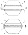
- a support element as shown in the figures 1 to 3 is shown.
- the support element shown in Figures 1 to 3 has a base surface 100 on which a web 110 is provided.
- the web 110 is with a bore 120 equipped.
- the support element is so between the eyelets arranged the clamping ring 14, that guided by the eyelet screw also is guided through the bore 120.
- the first direction of force runs perpendicular to one (imaginary) the two Eyelets connecting straight lines, based on the clamping ring 14 in particular in the radial Direction.
- the support element shown in Figures 1 to 3 has the disadvantage that it is difficult to center during assembly. Furthermore, can the support element shown in Figures 1 to 3 during the service life release the brake chamber, causing the mutual sealing of the two Housing halves 16, 18 may no longer be guaranteed under certain circumstances.
- the invention is therefore the object of developing the generic support elements such that accidental release of the support element is reliably avoided and its installation is still easy to perform.
- the support according to the invention is based on the generic state of Technique in that the support a first section and a reference this movable second section having the force in the first Force direction transfers to the object. Through mutual mobility of the first section and the second section, these sections can be mounted in the State of the support element so biased against each other arranged be that unintentional release of the support element is reliably avoided. In addition, the support element according to the invention can be during assembly center it more easily.
- the support element integrally formed and at least partially deformable, in particular elastically deformable.
- the deformability allows in particular that the dimensions of the support element at the decreasing during clamping of the clamping ring gap be adjusted between the eyelets of the clamping ring. In the assembled state of Ab rangelementes this is preferably on both loops of the clamping ring and then fills the entire space between these eyelets.
- the second section formed by a tongue is so attached to the first section that it is in a direction the straight line deformation of the first section on the object is pressed.
- the deformation of the first section is thereby during the Tensioning of the clamping ring caused while the loops of the clamping ring to move towards each other.
- the support element according to the invention provided that it has at least one first bore provided for this purpose is to receive a guided by at least one eyelet connecting means.
- at the fastening or connecting means may in particular to act a screw, which cooperates for clamping the clamping ring with a nut.
- the support By guided through the first bore connecting means is the support in the assembled state held securely in place.
- instead of the first bore only one Well or the like is provided, for example, with a through the Eyelets guided screw can interact.
- the first portion is formed substantially W-shaped. This embodiment is particularly considered when the W-shaped first Section is formed of a deformable material, in particular of an elastic deformable material.
- the support element according to the invention has a W-shaped first section
- the second portion at a free leg of the substantially W-shaped first portion is fixed.
- the second section may include the connection areas between the free thighs and the non-free thighs of the W-shaped one first section exert the force in the first direction of force on the second section. This applies in particular if these connection areas during clamping of the Clamping ring down, that is to move in the direction of the first direction of force, in particular by reducing the distance between the free ones Ends of the free legs of the W-shaped portion can be caused.
- the support element according to the invention further be provided that at least one of the free legs of the substantially W-shaped first portion provided leg a recess having.
- This recess is preferably mounted at least in the State of the support element with a first bore and / or a second bore aligned.
- one through the eyelets of the clamping ring and the first and second bore guided screw engage in the recess.
- This engagement is then preferably carried out such that the edge regions of the recess, in the assembled state of the support element, on the screw according to Art abut a stop.
- a stop is particularly advantageous when the connecting areas between the free thighs and the non-free ones Thighs the W-shaped first portion in the direction of the first direction of force should be moved or transmit a force in this direction.
- the invention also includes embodiments of the support element, in which provided that the first section and the second section by separate Parts are formed.
- the part forming the first section preferably has the first hole on. Also in this case, for example, one through the eyelets guided by the clamping ring screw through the first hole to the to hold the first section forming part of the place.
- the first section has an eccentricity and is rotatable about an axis of rotation is.
- the first force can then be generated by the first section is rotated, that the eccentricity causes the force in the first direction of force or transfers.
- the rotation of the first section can be done without it be limited after the tension ring was tensioned.
- the axis of rotation substantially is parallel to the line.
- a particularly preferred embodiment sees it before that the axis of rotation by a through the loops of the clamping ring and one in the first section provided first bore guided screw is formed, so that the axis of rotation and the straight line coincide.
- the eccentricity is in the support element according to the invention in order to align the eccentricity is in the support element according to the invention in In this context, preferably further provided that the first section in its outer peripheral region at least partially in the manner of a Mother is educated. This allows the eccentricity, for example, with the help of a Wrench be aligned properly.
- the support element is at least partially made Plastic is formed. This is especially true when the support element is completely or is partially elastic.
- the plastic is polypropylene.
- the second section has at least one web, which is intended to a collar to embrace the object.
- this collar may be one in the edge region of a housing half provided collar act.
- a first land one substantially perpendicular to the line and perpendicular to the first Force direction oriented force component in a second direction of force on the Exercises object and / or that a second bridge is a substantially vertical to the straight line and perpendicular to the first direction of force oriented force component in a third direction of force on the object exercises.
- the force components in particular on the the connecting portion of two housing halves forming collar are exercised, to bias the housing halves toward each other.
- the second direction of force and the third direction of force preferably opposite oriented. This can for example by V-shaped webs of the support element be achieved.
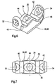
- the first portion 24 is formed substantially W-shaped, as can be seen in particular Figure 8.
- the W-shaped first section 24 a first free leg 40, whose free end portion angled in the illustrated case.
- the angled free end of the First free leg 40 is based on the illustrations of Figures 6 and 8 extended slightly downwards and has a first bore 32. Further points the first portion 24 has a second free leg 42, the free end portion thereof also angled. Also the free end section of the second free Leg 42 is extended downward, wherein in the second free leg a second bore 34 is provided.
- the W-shape of the first section 24 is through a first non-free leg 44 and a second non-free leg 46 completed.
- a recess 36 is provided in the connecting region of the first non-free leg 44 and the second non-free leg 46.
- the first Opening 32, the second opening 34 and the recess 36 are so with each other aligned so that a guided through the eyes of a clamping ring connecting means, in particular a screw, through the first opening 32, the second opening 34 and the recess 36 may extend.
- a clamping ring connecting means in particular a screw
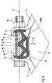
- FIG. 10 shows a schematic representation of the support element according to the figures 6 to 9 in an assembled state.
- a brake chamber consisting of two housing halves is formed, of which only the first housing half 16 can be seen in Figure 10 is.
- the first housing half 16 may be formed as shown in FIG be and has a first collar 62.
- the clamping ring 14 has a first eyelet 10 and a second eyelet 12. Between the first eyelet 10 and the second eyelet 12th is arranged with reference to the figures 6 to 9 explained supporting element.
- the fasteners 38 are formed by a screw and a nut, the Screw through the first eyelet 10, which provided in the second free leg 42 second bore 34, the recess 36, in the first free leg 40th provided first bore 32 and the second eyelet 12 is guided. If the to the Fastening or connecting means 38 belonging to the mother Tensioning of the clamping ring 14 is tightened, the distance between decreases the first eyelet 10 and the second eyelet 12. This will be between the first Eyelet 10 and the second eyelet 12 arranged elastic support member compressed.
- the connecting areas between the free legs 40, 42 and the non-free legs 44, 46 of the first section 24 based on the illustration of Figure 10 after pressed down.
- These connection areas press on the second section 26 forming the tongue 30, the force in the first direction of force 28 on the Connecting portion of the housing halves transfers, of which only the first half of the housing 16 is shown.
- the first force direction 28 extends perpendicular to an imaginary line 22 which connects the first eyelet 10 and the second eyelet 12.
- the tongue 30 thus seals at least a portion of the between the first eyelet 10th and the second eyelet 12 located connecting portion of the housing halves.
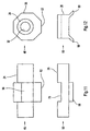
- FIGS. 11 and 12 show a second embodiment of the invention Support element shown, which is executed in this case two-piece.
- Figure 11 shows a side view while Figure 12 is a front view.
- the first portion 24 is formed by a first part 48
- the second portion 26 is formed by a second part 50.
- the first part 48 points a first bore 32 which is provided to a through the eyelets of a Clamp guided screw to record.
- the referring to the representation of Figure 11 central region of the first part 48 and the first portion 24 has an eccentricity 52.
- the eccentricity 52 is in one of a kind Nut formed portion of an outer peripheral portion 56 of the first section 24 formed.
- the first part 48 is attacked with a wrench, to turn the first part 48.
- the rotation of the first part 48 takes place such that the eccentricity 52 is a force in the first direction of force on the second section 26, which is formed by the second part 50.
- the second part 50 points at the In the embodiment shown in Figures 11 and 12, a seat 70 which is connected to the Dimensions of eccentricity 52 is adjusted.
- the second part 50 a first web 58 and a second web 60, these webs 58, 60 thereto are provided, provided on the housing halves 16, 18 of a brake chamber Collar 62, 64 to embrace.
- FIG. 13 shows a schematic representation of the support element according to the figures 11 and 12 in an assembled state.
- a partially shown clamping ring 14 is placed around a brake chamber by two housing halves is formed, of which in Figure 13, only the first housing half 16 can be seen.
- the clamping ring 14 again has a first eyelet 10 and a second Eyelet 12 on. Between the first eyelet 10 and the second eyelet 12 is based on the Figures 11 and 12 explained supporting element arranged.
- Connecting means 38 include a bolt and a nut, wherein the screw through the first eyelet 10, those provided in the first part 48 and the first section 24, respectively first bore 32 and the second eyelet 12 is guided.
- the first section 24 has a executed in the manner of a mother outer peripheral portion 56, which with a Eccentricity 52 is provided.
- the eccentricity 52 transmits a force in the first Force direction 28 on the second portion 26 and the second part 50, over the seat 70.
- the second section 26 transmits this force to the connection area the housing halves.
- the clamping ring 14 can be clamped, for example, while the Eccentricity 52 with respect to the illustration of Figure 13 still pointing upwards. After the clamping ring 14 has been tightened, you can with a wrench the outer peripheral region 56 of the first section, which is designed in the manner of a nut 24 are attacked to the first section 24 and the first part 48 to rotate about the screw, which counts to the connecting means 38.
- the straight line 22 and the axis of rotation 54 thus coincide.
- the first part 48 is rotated so far that the eccentricity 52 in the second Part 50 provided seat 70 engages, preferably engages.
- the first part 48 and the second part 50 and the first section 24 and the second section, respectively 26 are biased by each other so that the second section 26 transmits the force in the first direction of force 28 to the housing halves, wherein the first direction of force 28 with respect to the illustration of Figure 13 down and is oriented perpendicular to the line 22.
- first web 58 and the second web 60th are arranged at an angle to each other (see Figure 12), transmit the first web 58 and the second web 60 continue forces on the collar of the housing halves (only the collar 62 of the first housing half 16 can be seen in FIG. 13), the force components in a second direction of force 66 and a third direction of force 68 included.
- the second force direction 66 runs into the plane of drawing while the third direction of force 68 is from the plane of the drawing is oriented out.
- the housing halves are pressed together, which contributes to their mutual sealing.
Abstract
Description
Die Erfindung betrifft ein Abstützelement, das dazu vorgesehen ist, zumindest abschnittsweise zwischen zwei Ösen eines Spannrings angeordnet zu werden, insbesondere zwischen zwei Ösen eines zum Verbinden von zwei Gehäusehälften einer Bremskammer vorgesehenen Spannrings, um eine Kraft in einer ersten Kraftrichtung auf einen Gegenstand, insbesondere eine Bremskammer, auszuüben, die im Wesentlichen senkrecht zu einer die Ösen verbindenden Geraden orientiert ist.The invention relates to a support element, which is intended, at least in sections to be arranged between two eyelets of a clamping ring, in particular between two eyelets one for connecting two housing halves one Brake chamber provided clamping ring to a force in a first direction of force on an object, in particular a brake chamber, to exercise substantially is oriented perpendicular to a straight line connecting the eyelets.
Ein Spannring ohne Ösen ist beispielsweise aus der US 3,087,220 bekannt, wobei gemäß der Lehre dieser Druckschrift an einem freien Ende des Spannrings ein Spannelement vorgesehen ist, das eine Schraube umfasst, deren Gewinde zum Spannen des Spannrings in Ausnehmungen eingreift, die an dem anderen freien Ende des Spannrings vorgesehen sind.A clamping ring without eyelets is known for example from US 3,087,220, wherein according to the teaching of this document at a free end of the clamping ring a Clamping element is provided which comprises a screw whose thread for Clamping of the clamping ring engages in recesses which at the other free End of the clamping ring are provided.
Aus der GB 1 589 028 ist ein Spannring mit zwei Ösen bekannt, durch die zum Spannen des Spannrings eine Schraube geführt wird, die mit einer Mutter zusammenwirkt.From GB 1 589 028 a clamping ring with two eyelets is known by the Clamping the clamping ring is guided by a screw, which comes with a nut interacts.
Aus der US 4,109,250 ist ebenfalls ein Spannring mit zwei Ösen bekannt, durch die zum Spannen einer Schraube geführt wird, die mit einer Mutter zusammenwirkt, wobei der Spannring in diesem Fall zweiteilig ausgebildet ist.From US 4,109,250 a clamping ring with two loops is also known by the for tightening a screw that interacts with a nut, wherein the clamping ring is formed in two parts in this case.
Gattungsgemäße Abstützelemente werden beispielsweise im Zusammenhang mit
Bremskammern eingesetzt. Eine derartige Bremskammer ist in den Figuren 4 und 5
schematisch wiedergegeben, wobei die dargestellte Bremskammer aus einer ersten
Gehäusehälfte 16 und einer zweiten Gehäusehälfte 18 gebildet ist. Im Verbindungsbereich
der Gehäusehälften 16, 18 weist die erste Gehäusehälfte 16 einen Kragen
62 auf, während die Gehäusehälfte 18 einen Kragen 64 aufweist. Um derartige Gehäusehälften
16, 18 dicht miteinander zu verbinden, ist es bereits bekannt, einen
Spannring 14 zu verwenden. Ein derartiger Spannring 14 weist zwei Ösen auf (in
Figur 5 ist nur eine Öse 10 zu erkennen), die dazu vorgesehen sind, beispielsweise
mit Hilfe einer Schraube und einer Mutter zusammengezogen zu werden. Sofern die
Gehäusehälften 16, 18 Kragen 62, 64 aufweisen, umgreift der Spannring 14 vorzugsweise
diese Kragen 62, 64. Um auch den zwischen den Ösen des Spannrings
14 gelegenen Verbindungsbereich zwischen den Gehäusehälften 16, 18 abzudichten,
ist es bereits bekannt, ein Abstützelement zu verwenden, wie es in den Figuren
1 bis 3 dargestellt ist. Das in den Figuren 1 bis 3 dargestellte Abstützelement weist
eine Basisfläche 100 auf, auf der ein Steg 110 vorgesehen ist. Der Steg 110 ist mit
einer Bohrung 120 ausgestattet. Das Abstützelement wird derart zwischen den Ösen
des Spannrings 14 angeordnet, dass die durch die Ösen geführte Schraube auch
durch die Bohrung 120 geführt wird. Beim Spannen des Spannrings 14 übt das Abstützelement
mit seiner Basisfläche 100 eine Kraft in einer ersten Kraftrichtung auf
den zwischen den Ösen gelegenen Verbindungsbereich der Gehäusehälften 16, 18
auf. Die erste Kraftrichtung verläuft dabei senkrecht zu einer (gedachten) die beiden
Ösen verbindenden Geraden, bezogen auf den Spannring 14 insbesondere in radialer
Richtung. Das in den Figuren 1 bis 3 dargestellte Abstützelement weist jedoch
den Nachteil auf, dass es bei der Montage schwierig zu zentrieren ist. Weiterhin kann
sich das in den Figuren 1 bis 3 dargestellte Abstützelement während der Nutzungsdauer
der Bremskammer lösen, wodurch die gegenseitige Abdichtung der beiden
Gehäusehälften 16, 18 unter Umständen nicht mehr gewährleistet ist.Generic support elements are, for example, in connection with
Brake chambers used. Such a brake chamber is shown in FIGS. 4 and 5
shown schematically, wherein the illustrated brake chamber of a
Der Erfindung liegt daher die Aufgabe zugrunde, die gattungsgemäßen Abstützelemente derart weiterzubilden, dass ein unbeabsichtigtes Lösen des Abstützelements sicher vermieden wird und dessen Montage trotzdem einfach durchzuführen ist.The invention is therefore the object of developing the generic support elements such that accidental release of the support element is reliably avoided and its installation is still easy to perform.
Diese Aufgabe wird durch die Merkmale des Anspruchs 1 gelöst.This object is solved by the features of claim 1.
Vorteilhafte Ausgestaltungen und Weiterbildungen der Erfindung ergeben sich aus den Unteransprüchen.Advantageous embodiments and further developments of the invention will become apparent the dependent claims.
Das erfindungsgemäße Abstützelement baut auf dem gattungsgemäßen Stand der Technik dadurch auf, dass das Abstützelement einen ersten Abschnitt und einen bezüglich diesem beweglichen zweiten Abschnitt aufweist, der die Kraft in der ersten Kraftrichtung auf den Gegenstand überträgt. Durch die gegenseitige Beweglichkeit des ersten Abschnitts und des zweiten Abschnitts können diese Abschnitte im montierten Zustand des Abstützelements derart gegeneinander vorgespannt angeordnet sein, dass ein unbeabsichtigtes Lösen des Abstützelementes sicher vermieden wird. Darüber hinaus lässt sich das erfindungsgemäße Abstützelement bei der Montage leichter zentrieren.The support according to the invention is based on the generic state of Technique in that the support a first section and a reference this movable second section having the force in the first Force direction transfers to the object. Through mutual mobility of the first section and the second section, these sections can be mounted in the State of the support element so biased against each other arranged be that unintentional release of the support element is reliably avoided. In addition, the support element according to the invention can be during assembly center it more easily.
Bei einer ersten vorteilhaften Weiterbildung des erfindungsgemäßen Abstützelementes ist vorgesehen, dass das Abstützelement einstückig ausgebildet und zumindest abschnittsweise verformbar, insbesondere elastisch verformbar ist. Die Verformbarkeit ermöglicht es insbesondere, dass die Abmessungen des Abstützelementes an den sich beim Spannen des Spannrings verkleinernden Zwischenraum zwischen den Ösen des Spannrings angepasst werden. Im montierten Zustand des Abstützelementes liegt dieses vorzugsweise an beiden Ösen des Spannrings an und füllt dann den gesamten Zwischenraum zwischen diesen Ösen aus. In a first advantageous embodiment of the support element according to the invention is provided that the support element integrally formed and at least partially deformable, in particular elastically deformable. The deformability allows in particular that the dimensions of the support element at the decreasing during clamping of the clamping ring gap be adjusted between the eyelets of the clamping ring. In the assembled state of Abstützelementes this is preferably on both loops of the clamping ring and then fills the entire space between these eyelets.
Insbesondere in diesem Zusammenhang kann bei dem erfindungsgemäßen Abstützelement weiterhin vorgesehen sein, dass der zweite Abschnitt durch eine Zunge gebildet ist, die derart an dem ersten Abschnitt befestigt ist, dass sie bei einer in Richtung der Geraden erfolgenden Verformung des ersten Abschnitts auf den Gegenstand gedrückt wird. Die Verformung des ersten Abschnitts wird dabei während des Spannens des Spannrings hervorgerufen, während sich die Ösen des Spannrings aufeinander zu bewegen.In particular, in this context, in the support element according to the invention be further provided that the second section formed by a tongue is so attached to the first section that it is in a direction the straight line deformation of the first section on the object is pressed. The deformation of the first section is thereby during the Tensioning of the clamping ring caused while the loops of the clamping ring to move towards each other.
Bei bevorzugten Ausführungsformen des erfindungsgemäßen Abstützelementes ist vorgesehen, dass es zumindest eine erste Bohrung aufweist, die dazu vorgesehen ist, ein durch zumindest eine Öse geführtes Verbindungsmittel aufzunehmen. Bei dem Befestigungs- beziehungsweise Verbindungsmittel kann es sich insbesondere um eine Schraube handeln, die zum Spannen des Spannrings mit einer Mutter zusammenwirkt. Durch das durch die erste Bohrung geführte Verbindungsmittel wird das Abstützelement im montierten Zustand sicher an seinem Platz gehalten. Altemativ sind Ausführungsformen denkbar, bei denen anstelle der ersten Bohrung nur eine Vertiefung oder dergleichen vorgesehen ist, die beispielsweise mit einer durch die Ösen geführten Schraube zusammenwirken kann.In preferred embodiments of the support element according to the invention provided that it has at least one first bore provided for this purpose is to receive a guided by at least one eyelet connecting means. at the fastening or connecting means may in particular to act a screw, which cooperates for clamping the clamping ring with a nut. By guided through the first bore connecting means is the support in the assembled state held securely in place. Alternatively embodiments are conceivable in which instead of the first bore only one Well or the like is provided, for example, with a through the Eyelets guided screw can interact.
Bei einer bevorzugten Ausführungsform des erfindungsgemäßen Abstützelementes ist vorgesehen, dass der erste Abschnitt im Wesentlichen W-förmig ausgebildet ist. Diese Ausführungsform kommt insbesondere in Betracht, wenn der W-förmige erste Abschnitt aus einem verformbaren Material gebildet ist, insbesondere aus einem elastisch verformbaren Material.In a preferred embodiment of the support element according to the invention it is provided that the first portion is formed substantially W-shaped. This embodiment is particularly considered when the W-shaped first Section is formed of a deformable material, in particular of an elastic deformable material.
In diesem Zusammenhang sieht eine vorteilhafte Weiterbildung des erfindungsgemäßen Abstützelementes vor, dass in dem ersten freien Schenkel des im Wesentlichen W-förmigen ersten Abschnitts eine erste Bohrung und in dem zweiten freien Schenkel des im Wesentlichen W-förmigen Abschnitts eine zweite Bohrung vorgesehen ist. In diesem Fall ist es beispielsweise möglich, eine durch die Ösen geführte Schraube zusätzlich durch die erste Bohrung und die zweite Bohrung zu führen, wodurch auch eine unerwünschte Verdrehung des Abstützelementes, beispielsweise um eine zur ersten Kraftrichtung parallele Drehachse, sicher vermieden werden kann.In this context, an advantageous development of the invention Abstützelementes ago that in the first free leg of the substantially W-shaped first section a first hole and in the second free Leg of the substantially W-shaped portion provided a second bore is. In this case, it is possible, for example, a guided through the eyelets In addition, screw through the first hole and the second hole to guide, thereby also an undesired rotation of the support element, for example around a parallel to the first direction of force axis of rotation can be safely avoided can.
Wenn das erfindungsgemäße Abstützelement einen W-förmigen ersten Abschnitt aufweist, ist vorzugsweise weiterhin vorgesehen, dass der zweite Abschnitt an einem freien Schenkel des im Wesentlichen W-förmigen ersten Abschnitts befestigt ist. Bei einer derartigen Anordnung des zweiten Abschnitts können die Verbindungsbereiche zwischen den freien Schenkeln und den nicht-freien Schenkeln des W- förmigen ersten Abschnitts die Kraft in der ersten Kraftrichtung auf den zweiten Abschnitt ausüben. Dies gilt insbesondere, wenn diese Verbindungsbereiche beim Spannen des Spannrings nach unten, das heißt in Richtung der ersten Kraftrichtung bewegt werden, was insbesondere durch eine Verkleinerung des Abstands zwischen den freien Enden der freien Schenkel des W-förmigen Abschnitts hervorgerufen werden kann.If the support element according to the invention has a W-shaped first section Preferably, it is further provided that the second portion at a free leg of the substantially W-shaped first portion is fixed. at Such an arrangement of the second section may include the connection areas between the free thighs and the non-free thighs of the W-shaped one first section exert the force in the first direction of force on the second section. This applies in particular if these connection areas during clamping of the Clamping ring down, that is to move in the direction of the first direction of force, in particular by reducing the distance between the free ones Ends of the free legs of the W-shaped portion can be caused.
In diesem Zusammenhang kann bei dem erfindungsgemäßen Abstützelement weiterhin vorgesehen sein, dass zumindest einer der zwischen den freien Schenkeln des im Wesentlichen W-förmigen ersten Abschnitts vorgesehenen Schenkel eine Ausnehmung aufweist. Diese Ausnehmung ist vorzugsweise zumindest im montierten Zustand des Abstützelementes mit einer ersten Bohrung und/oder einer zweiten Bohrung ausgerichtet. Dadurch kann beispielsweise eine durch die Ösen des Spannrings und die erste und zweite Bohrung geführte Schraube in die Ausnehmung eingreifen. Dieser Eingriff erfolgt dann vorzugsweise derart, dass die Randbereiche der Ausnehmung, im montierten Zustand des Abstützelementes, an der Schraube nach Art eines Anschlags anliegen. Ein derartiger Anschlag ist insbesondere vorteilhaft, wenn die Verbindungsbereiche zwischen den freien Schenkeln und den nicht-freien Schenkeln des W- förmigen ersten Abschnitts in Richtung der ersten Kraftrichtung bewegt werden sollen oder eine Kraft in dieser Richtung übertragen sollen.In this context, in the support element according to the invention further be provided that at least one of the free legs of the substantially W-shaped first portion provided leg a recess having. This recess is preferably mounted at least in the State of the support element with a first bore and / or a second bore aligned. As a result, for example, one through the eyelets of the clamping ring and the first and second bore guided screw engage in the recess. This engagement is then preferably carried out such that the edge regions of the recess, in the assembled state of the support element, on the screw according to Art abut a stop. Such a stop is particularly advantageous when the connecting areas between the free thighs and the non-free ones Thighs the W-shaped first portion in the direction of the first direction of force should be moved or transmit a force in this direction.
Die Erfindung umfasst auch Ausführungsformen des Abstützelementes, bei denen vorgesehen ist, dass der erste Abschnitt und der zweite Abschnitt durch getrennte Teile gebildet sind. Dabei weist das den ersten Abschnitt bildende Teil vorzugsweise die erste Bohrung auf. Auch in diesem Fall kann beispielsweise eine durch die Ösen des Spannrings geführte Schraube durch die erste Bohrung geführt werden, um das den ersten Abschnitt bildende Teil am Platz zu halten. The invention also includes embodiments of the support element, in which provided that the first section and the second section by separate Parts are formed. In this case, the part forming the first section preferably has the first hole on. Also in this case, for example, one through the eyelets guided by the clamping ring screw through the first hole to the to hold the first section forming part of the place.
Insbesondere in diesem Zusammenhang ist vorzugsweise weiterhin vorgesehen, dass der erste Abschnitt eine Exzentrizität aufweist und um eine Drehachse drehbar ist. Die erste Kraft kann dann dadurch erzeugt werden, dass der erste Abschnitt so gedreht wird, dass die Exzentrizität die Kraft in der ersten Kraftrichtung hervorruft beziehungsweise überträgt. Die Drehung des ersten Abschnitts kann ohne darauf beschränkt zu sein erfolgen, nachdem der Spannring gespannt wurde.In particular, in this context is preferably still provided in that the first section has an eccentricity and is rotatable about an axis of rotation is. The first force can then be generated by the first section is rotated, that the eccentricity causes the force in the first direction of force or transfers. The rotation of the first section can be done without it be limited after the tension ring was tensioned.
Im vorstehend erläuterten Zusammenhang ist bei dem erfindungsgemäßen Abstützelement vorzugsweise weiterhin vorgesehen, dass die Drehachse im Wesentlichen parallel zu der Geraden ist. Eine besonders bevorzugte Ausführungsform sieht dabei vor, dass die Drehachse durch eine durch die Ösen des Spannrings und eine in dem ersten Abschnitt vorgesehene erste Bohrung geführte Schraube gebildet wird, so dass die Drehachse und die Gerade zusammenfallen.In the context described above is in the support element according to the invention preferably further provided that the axis of rotation substantially is parallel to the line. A particularly preferred embodiment sees it before that the axis of rotation by a through the loops of the clamping ring and one in the first section provided first bore guided screw is formed, so that the axis of rotation and the straight line coincide.
Um die Exzentrizität auszurichten ist bei dem erfindungsgemäßen Abstützelement in diesem Zusammenhang vorzugsweise weiterhin vorgesehen, dass der erste Abschnitt in seinem Außenumfangsbereich zumindest abschnittsweise nach Art einer Mutter ausgebildet ist. Dadurch kann die Exzentrizität beispielsweise mit Hilfe eines Schraubenschlüssels geeignet ausgerichtet werden.In order to align the eccentricity is in the support element according to the invention in In this context, preferably further provided that the first section in its outer peripheral region at least partially in the manner of a Mother is educated. This allows the eccentricity, for example, with the help of a Wrench be aligned properly.
Unabhängig von der speziellen Ausgestaltung des erfindungsgemäßen Abstützelementes sehen bevorzugte Ausführungsformen vor, dass es zumindest teilweise aus Kunststoff gebildet ist. Dies gilt insbesondere, wenn das Abstützelement ganz oder teilweise elastisch ausgebildet ist.Regardless of the specific embodiment of the support element according to the invention For example, preferred embodiments provide that it is at least partially made Plastic is formed. This is especially true when the support element is completely or is partially elastic.
Dabei kann insbesondere vorgesehen sein, dass der Kunststoff Polypropylen ist.It may be provided in particular that the plastic is polypropylene.
Eine Weiterbildung des erfindungsgemäßen Abstützelementes sieht vor, dass der zweite Abschnitt zumindest einen Steg aufweist, der dazu vorgesehen ist, einen Kragen des Gegenstandes zu umgreifen. Im Zusammenhang mit einer Bremskammer kann es sich bei diesem Kragen insbesondere um einen im Randbereich einer Gehäusehälfte vorgesehenen Kragen handeln. A development of the support element according to the invention provides that the second section has at least one web, which is intended to a collar to embrace the object. In connection with a brake chamber in particular, this collar may be one in the edge region of a housing half provided collar act.
Weiterhin kann bei dem erfindungsgemäßen Abstützelement vorgesehen sein, dass ein erster Steg eine im Wesentlichen senkrecht zur Geraden und senkrecht zur ersten Kraftrichtung orientierte Kraftkomponente in einer zweiten Kraftrichtung auf den Gegenstand ausübt und/oder dass ein zweiter Steg eine im Wesentlichen senkrecht zur Geraden und senkrecht zur ersten Kraftrichtung orientierte Kraftkomponente in einer dritten Kraftrichtung auf den Gegenstand ausübt. Beispielsweise im Zusammenhang mit Bremskammern können die Kraftkomponenten insbesondere auf die den Verbindungsbereich von zwei Gehäusehälften bildenden Kragen ausgeübt werden, um die Gehäusehälften aufeinander zu vorzuspannen. Zu diesem Zweck sind die zweite Kraftrichtung und die dritte Kraftrichtung vorzugsweise entgegengesetzt orientiert. Dies kann beispielsweise durch V-förmig angeordnete Stege des Abstützelementes erreicht werden.Furthermore, it can be provided in the support element according to the invention that a first land one substantially perpendicular to the line and perpendicular to the first Force direction oriented force component in a second direction of force on the Exercises object and / or that a second bridge is a substantially vertical to the straight line and perpendicular to the first direction of force oriented force component in a third direction of force on the object exercises. For example, in context with brake chambers, the force components in particular on the the connecting portion of two housing halves forming collar are exercised, to bias the housing halves toward each other. For this purpose are the second direction of force and the third direction of force preferably opposite oriented. This can for example by V-shaped webs of the support element be achieved.
Ausführungsbeispiele der Erfindung werden nachfolgend anhand der zugehörigen Zeichnungen näher erläutert.Embodiments of the invention are described below with reference to the associated Drawings explained in more detail.
Es zeigen:
- Figur 1
- eine Seitenansicht eines Abstützelementes gemäß dem Stand der Technik;
- Figur 2
- eine Vorderansicht des Abstützelementes gemäß Figur 1;
- Figur 3
- eine Draufsicht des Abstützelementes gemäß Figur 1;
- Figur 4
- eine Ausführungsform einer durch zwei Gehäusehälften gebildeten Bremskammer;
- Figur 5
- die Gehäusehälften gemäß Figur 4 in einem durch einen Spannring verbundenen Zustand;
- Figur 6
- eine perspektivische Darstellung einer ersten Ausführungsform des erfindungsgemäßen Abstützelements;
- Figur 7
- eine Draufsicht des Abstützelements gemäß Figur 6;
- Figur 8
- eine Seitenansicht des Abstützelements gemäß Figur 6;
- Figur 9
- eine Vorderansicht des Abstützelements gemäß Figur 6;
Figur 10- eine schematische Darstellung des Abstützelements gemäß den Figuren 6 bis 9 in einem montierten Zustand;
- Figur 11
- eine Seitenansicht einer zweiten Ausführungsform des erfindungsgemäßen Abstützelementes, bei dem der erste Abschnitt und der zweite Abschnitt durch getrennte Teile gebildet sind;
Figur 12- eine Vorderansicht des Abstützelementes gemäß Figur 11; und
- Figur 13
- eine schematische Darstellung des Abstützelements gemäß den Figuren 11 und 12 in einem montierten Zustand.
- FIG. 1
- a side view of a support element according to the prior art;
- FIG. 2
- a front view of the support element of Figure 1;
- FIG. 3
- a plan view of the support element of Figure 1;
- FIG. 4
- an embodiment of a brake chamber formed by two housing halves;
- FIG. 5
- the housing halves of Figure 4 in a state connected by a clamping ring state;
- FIG. 6
- a perspective view of a first embodiment of the support element according to the invention;
- FIG. 7
- a plan view of the support member of Figure 6;
- FIG. 8
- a side view of the support member of Figure 6;
- FIG. 9
- a front view of the support member of Figure 6;
- FIG. 10
- a schematic representation of the support member according to Figures 6 to 9 in an assembled state;
- FIG. 11
- a side view of a second embodiment of the support element according to the invention, in which the first portion and the second portion are formed by separate parts;
- FIG. 12
- a front view of the support element of Figure 11; and
- FIG. 13
- a schematic representation of the support member according to Figures 11 and 12 in an assembled state.
Die in den Zeichnungen dargestellten Ausführungsformen des erfindungsgemäßen Abstützelementes können beispielsweise anstelle des in den Figuren 1 bis 3 dargestellten bekannten Abstützelementes verwendet werden, insbesondere im Zusammenhang mit einer Bremskammer, wie sie in den eingangs erläuterten Figuren 4 und 5 dargestellt ist.The embodiments of the invention shown in the drawings Supporting element, for example, instead of that shown in Figures 1 to 3 known support element are used, in particular in context with a brake chamber, as in the above-explained Figures 4 and 5 is shown.
Bei der in den Figuren 6 bis 9 dargestellten Ausführungsform des erfindungsgemäßen
Abstützelementes ist der erste Abschnitt 24 im Wesentlichen W-förmig ausgebildet,
wie dies insbesondere Figur 8 zu entnehmen ist. Zu diesem Zweck weist der W-förmige
erste Abschnitt 24 einen ersten freien Schenkel 40 auf, dessen freier Endabschnitt
im dargestellten Fall abgewinkelt ist. Der abgewinkelte freie Endabschnitt des
ersten freien Schenkels 40 ist bezogen auf die Darstellungen der Figuren 6 und 8
nach unten etwas verlängert und weist eine erste Bohrung 32 auf. Weiterhin weist
der erste Abschnitt 24 einen zweiten freien Schenkel 42 auf, dessen freier Endabschnitt
ebenfalls abgewinkelt ist. Auch der freie Endabschnitt des zweiten freien
Schenkels 42 ist nach unten verlängert, wobei in dem zweiten freien Schenkel eine
zweite Bohrung 34 vorgesehen ist. Die W-Form des ersten Abschnitts 24 wird durch
einen ersten nicht-freien Schenkel 44 und einen zweiten nicht-freien Schenkel 46
vervollständigt. Im Verbindungsbereich des ersten nicht-freien Schenkels 44 und des
zweiten nicht-freien Schenkels 46 ist eine Ausnehmung 36 vorgesehen. Die erste
Öffnung 32, die zweite Öffnung 34 und die Ausnehmung 36 sind derart miteinander
ausgerichtet, dass ein durch die Ösen eines Spannrings geführtes Verbindungsmittel,
insbesondere eine Schraube, sich durch die erste Öffnung 32, die zweite Öffnung
34 und die Ausnehmung 36 erstrecken kann. Bei der in den Figuren 6 bis 9 dargestellten
Ausführungsform des erfindungsgemäßen Abstützelementes ist der zweite
Abschnitt 26 durch eine Zunge 30 gebildet. Die Zunge 30 ist an dem zweiten freien
Schenkel 42 befestigt und weist ihrerseits einen freien Endabschnitt auf. Die in den
Figuren 6 bis 9 dargestellte Ausführungsform des erfindungsgemäßen Abstützelementes
ist aus einem elastisch verformbaren Material hergestellt, insbesondere aus
Polypropylen.In the embodiment of the invention shown in Figures 6 to 9
Supporting element, the
Figur 10 zeigt eine schematische Darstellung des Abstützelements gemäß den Figuren
6 bis 9 in einem montierten Zustand. Gemäß der Darstellung von Figur 10 umgibt
ein nur teilweise dargestellter Spannring 14 eine Bremskammer die aus zwei Gehäusehälften
gebildet ist, von denen in Figur 10 nur die erste Gehäusehälfte 16 zu erkennen
ist. Die erste Gehäusehälfte 16 kann wie in Figur 4 dargestellt ausgebildet
sein und weist einen ersten Kragen 62 auf. Der Spannring 14 weist eine erste Öse
10 und eine zweite Öse 12 auf. Zwischen der ersten Öse 10 und der zweiten Öse 12
ist das anhand der Figuren 6 bis 9 erläuterte Abstützelement angeordnet. Die Befestigungsmittel
38 sind durch eine Schraube und eine Mutter gebildet, wobei die
Schraube durch die erste Öse 10, die in dem zweiten freien Schenkel 42 vorgesehene
zweite Bohrung 34, die Ausnehmung 36, die in dem ersten freien Schenkel 40
vorgesehene erste Bohrung 32 und die zweite Öse 12 geführt ist. Wenn die zu den
Befestigungs- beziehungsweise Verbindungsmitteln 38 gehörende Mutter zum
Spannen des Spannrings 14 angezogen wird, verringert sich der Abstand zwischen
der ersten Öse 10 und der zweiten Öse 12. Dadurch wird das zwischen der ersten
Öse 10 und der zweiten Öse 12 angeordnete elastische Abstützelement zusammengedrückt.
Da die in den nicht-freien Schenkeln 44, 46 des ersten Abschnitts 24 vorgesehene
Ausnehmung 36 einen Anschlag für die Schraube bildet, werden die Verbindungsbereiche
zwischen den freien Schenkeln 40, 42 und den nicht-freien Schenkeln
44, 46 des ersten Abschnitts 24 bezogen auf die Darstellung von Figur 10 nach
unten gedrückt. Dabei drücken diese Verbindungsbereiche auf die den zweiten Abschnitt
26 bildende Zunge 30, die die Kraft in der ersten Kraftrichtung 28 auf den
Verbindungsbereich der Gehäusehälften überträgt, von denen nur die erste Gehäusehälfte
16 dargestellt ist. Die erste Kraftrichtung 28 erstreckt sich dabei senkrecht zu
einer (gedachten) Geraden 22, die die erste Öse 10 und die zweite Öse 12 verbindet.
Die Zunge 30 dichtet somit zumindest einen Teil des zwischen der ersten Öse 10
und der zweiten Öse 12 gelegenen Verbindungsbereiches der Gehäusehälften ab.FIG. 10 shows a schematic representation of the support element according to the figures
6 to 9 in an assembled state. As shown in FIG. 10, surrounds
an only partially illustrated clamping
In den Figuren 11 und 12 ist eine zweite Ausführungsform des erfindungsgemäßen
Abstützelementes dargestellt, das in diesem Fall zweistückig ausgeführt ist. Dabei
zeigt Figur 11 eine Seitenansicht, während Figur 12 eine Vorderansicht ist. Bei dieser
Ausführungsform ist der erste Abschnitt 24 durch ein erstes Teil 48 gebildet, während
der zweite Abschnitt 26 durch ein zweites Teil 50 gebildet ist. Das erste Teil 48 weist
eine erste Bohrung 32 auf, die dazu vorgesehen ist, eine durch die Ösen eines
Spannrings geführte Schraube aufzunehmen. Der bezogen auf die Darstellung von
Figur 11 mittlere Bereich des ersten Teils 48 beziehungsweise des ersten Abschnitts
24 weist eine Exzentrizität 52 auf. Die Exzentrizität 52 ist in einem nach Art einer
Mutter gebildeten Abschnitt eines Außenumfangsbereiches 56 des ersten Abschnitts
24 gebildet. An diesem Außenumfangsbereich 56 kann während oder nach der
Montage des Abstützelementes, beziehungsweise während oder nach dem Spannen
eines Spannrings, beispielsweise mit einem Schraubenschlüssel angegriffen werden,
um das erste Teil 48 zu drehen. Die Drehung des ersten Teils 48 erfolgt derart, dass
die Exzentrizität 52 eine Kraft in der ersten Kraftrichtung auf den zweiten Abschnitt
26 ausübt, der durch das zweite Teil 50 gebildet ist. Das zweite Teil 50 weist bei der
in den Figuren 11 und 12 dargestellten Ausführungsform einen Sitz 70 auf, der an die
Abmessungen der Exzentrizität 52 angepasst ist. Weiterhin weist das zweite Teil 50
einen ersten Steg 58 und einen zweiten Steg 60 auf, wobei diese Stege 58, 60 dazu
vorgesehen sind, an den Gehäusehälften 16, 18 einer Bremskammer vorgesehene
Kragen 62, 64 zu umgreifen. Im montierten Zustand des Abstützelementes übertragen
die Stege 58, 60 Kräfte auf die Kragen 62, 64, wobei diese Kräfte Kraftkomponenten
in einer zweiten Kraftrichtung 66 und einer dritten Kraftrichtung 68 (siehe Figur
13) aufweisen, um die Gehäusehälften 16, 18 gegeneinander zu drücken. FIGS. 11 and 12 show a second embodiment of the invention
Support element shown, which is executed in this case two-piece. there
Figure 11 shows a side view while Figure 12 is a front view. At this
Embodiment, the
Figur 13 zeigt eine schematische Darstellung des Abstützelements gemäß den Figuren
11 und 12 in einem montierten Zustand. Gemäß der Darstellung von Figur 13 ist
ein nur teilweise dargestellter Spannring 14 um eine Bremskammer gelegt, die durch
zwei Gehäusehälften gebildet ist, von denen in Figur 13 nur die erste Gehäusehälfte
16 zu erkennen ist. Der Spannring 14 weist wieder eine erste Öse 10 und eine zweite
Öse 12 auf. Zwischen der ersten Öse 10 und der zweiten Öse 12 ist das anhand der
Figuren 11 und 12 erläuterte Abstützelement angeordnet. Verbindungsmittel 38 umfassen
eine Schraube und eine Mutter, wobei die Schraube durch die erste Öse 10,
die in dem ersten Teil 48 beziehungsweise dem ersten Abschnitt 24 vorgesehene
erste Bohrung 32 und die zweite Öse 12 geführt ist. Der erste Abschnitt 24 weist einen
nach Art einer Mutter ausgeführten Außenumfangsbereich 56 auf, der mit einer
Exzentrizität 52 versehen ist. Die Exzentrizität 52 überträgt eine Kraft in der ersten
Kraftrichtung 28 auf den zweiten Abschnitt 26 beziehungsweise das zweite Teil 50,
über den Sitz 70. Der zweite Abschnitt 26 überträgt diese Kraft auf den Verbindungsbereich
der Gehäusehälften. Um den in Figur 13 dargestellten Montageendzustand
zu erzielen, kann der Spannring 14 beispielsweise gespannt werden, während die
Exzentrizität 52 bezogen auf die Darstellung von Figur 13 noch nach oben zeigt.
Nachdem der Spannring 14 gespannt wurde, kann mit einem Schraubenschlüssel an
dem nach Art einer Mutter ausgebildeten Außenumfangsbereich 56 des ersten Abschnitts
24 angegriffen werden, um den ersten Abschnitt 24 beziehungsweise das
erste Teil 48 um die Schraube zu drehen, die zu den Verbindungsmitteln 38 zählt.
Bei dieser Anordnung fällt die Gerade 22 und die Drehachse 54 somit zusammen.
Das erste Teil 48 wird so weit gedreht, dass die Exzentrizität 52 in den in dem zweiten
Teil 50 vorgesehenen Sitz 70 eingreift, vorzugsweise einrastet. Das erste Teil 48
und das zweite Teil 50 beziehungsweise der erste Abschnitt 24 und der zweite Abschnitt
26 werden dadurch derart gegenseitig vorgespannt, dass der zweite Abschnitt
26 die Kraft in der ersten Kraftrichtung 28 auf die Gehäusehälften überträgt, wobei
die erste Kraftrichtung 28 bezogen auf die Darstellung von Figur 13 nach unten und
senkrecht zur Geraden 22 orientiert ist. Da der erste Steg 58 und der zweite Steg 60
unter einem Winkel zueinander angeordnet sind (siehe Figur 12), übertragen der
erste Steg 58 und der zweite Steg 60 weiterhin Kräfte auf die Kragen der Gehäusehälften
(in Figur 13 ist nur der Kragen 62 der ersten Gehäusehälfte 16 zu erkennen),
die Kraftkomponenten in einer zweiten Kraftrichtung 66 und einer dritten Kraftrichtung
68 enthalten. Wie dies in Figur 13 angedeutet ist verläuft die zweite Kraftrichtung 66
in die Zeichenebene hinein, während die dritte Kraftrichtung 68 aus der Zeichenebene
heraus orientiert ist. Durch die Kraftkomponenten in die zweite Kraftrichtung 66
und die dritte Kraftrichtung 68 werden die Gehäusehälften zusammen gedrückt, was
zu deren gegenseitiger Abdichtung beiträgt.FIG. 13 shows a schematic representation of the support element according to the figures
11 and 12 in an assembled state. As shown in FIG. 13
a partially shown clamping
Claims (16)
- Support element designed to fit in at least certain regions between two eyes (10, 12) of a clamping ring (14), in particular between two eyes (10, 12) of a clamping ring used to connect two housing halves (16, 18) of a brake chamber, in order to transmit a force to an object (20) in a first force direction (28) oriented essentially perpendicular to a straight line (22) connecting the eyes (10, 12), characterised in that the support element has a first section (24) and a second section (26) displaceable relative to it, which transmits force to the object (20) in the first force direction (28).
- Support element as claimed in claim 1, characterised in that the support element is made from a single piece and is deformable in certain regions, in particular elastically deformable.
- Support element as claimed in claim 1 or 2, characterised in that the second section (26) is provided in the form of a tongue (30) which is secured to the first section (24) so that it is pressed against the object (20) when the first section (24) is deformed in the direction of the straight line (22).
- Support element as claimed in one of the preceding claims, characterised in that it has at least a first bore (32) provided as a means of accommodating connecting means (38) inserted through at least one eye (10, 12).
- Support element as claimed in one of the preceding claims, characterised in that the first section (24) is essentially of a W-shaped design.
- Support element as claimed in claim 5, characterised in that a first bore (32) is provided in the first free leg (40) of the essentially W-shaped first section (24) and a second bore (34) is provided in the second free leg (42) of the essentially W-shaped section.
- Support element as claimed in claim 5 or 6, characterised in that the second section (26) is secured to a free leg (42) of the essentially W-shaped first section (24).
- Support element as claimed in one of claims 5 to 7, characterised in that at least one of the legs (44, 46b) disposed between the free legs (40, 42) of the essentially W-shaped first section (24) has a recess (36).
- Support element as claimed in claim 1 or in one of claims 3 to 8, characterised in that the first section (24) and the second section (26) are made as separate parts.
- Support element as claimed in one of the preceding claims, characterised in that the first section (24) has an eccentricity (52) and is rotatable about an axis of rotation (54).
- Support element as claimed in claim 10, characterised in that the axis of rotation (54) is essentially parallel with the straight line (22).
- Support element as claimed in claim 10 or 11, characterised in that the first section (24) is designed in the form of a nut in at least certain regions of its outer peripheral region (56)
- Support element as claimed in one of the preceding claims, characterised in that it is at least partially made from plastic.
- Support element as claimed in claim 13, characterised in that the plastic is polypropylene.
- Support element as claimed in one of the preceding claims, characterised in that the second section (26) has at least one web (58, 60) provided as a means of engaging round a collar (62, 64) of the object.
- Support element as claimed in one of the preceding claims, characterised in that a first web (58) transmits a force component to the object (20) in a second force direction (66) oriented essentially perpendicular to the straight line (22) and perpendicular to the first force direction (28) and/or a second web (60) transmits a force component to the object (20) in a third force direction (68) oriented essentially perpendicular to the straight line (22) and perpendicular to the first force direction (28).
Applications Claiming Priority (2)
| Application Number | Priority Date | Filing Date | Title |
|---|---|---|---|
| DE10153029A DE10153029A1 (en) | 2001-10-26 | 2001-10-26 | supporting |
| DE10153029 | 2001-10-26 |
Publications (2)
| Publication Number | Publication Date |
|---|---|
| EP1306280A1 EP1306280A1 (en) | 2003-05-02 |
| EP1306280B1 true EP1306280B1 (en) | 2005-09-07 |
Family
ID=7703899
Family Applications (1)
| Application Number | Title | Priority Date | Filing Date |
|---|---|---|---|
| EP02022985A Expired - Lifetime EP1306280B1 (en) | 2001-10-26 | 2002-10-14 | Supporting element for a clamp band |
Country Status (3)
| Country | Link |
|---|---|
| EP (1) | EP1306280B1 (en) |
| AT (1) | ATE303925T1 (en) |
| DE (2) | DE10153029A1 (en) |
Families Citing this family (1)
| Publication number | Priority date | Publication date | Assignee | Title |
|---|---|---|---|---|
| DE102004044939B4 (en) * | 2004-04-21 | 2007-08-16 | Knorr-Bremse Systeme für Nutzfahrzeuge GmbH | Mounting clamp for brake cylinder |
Family Cites Families (11)
| Publication number | Priority date | Publication date | Assignee | Title |
|---|---|---|---|---|
| DE8404035U1 (en) * | 1984-06-07 | Knorr-Bremse GmbH, 8000 München | Tension band for the housing of membrane cylinders, in particular for brake cylinders of motor vehicles | |
| US3087220A (en) * | 1960-09-15 | 1963-04-30 | Page Mfg Company Du | Worm drive hose clamp |
| DE2230991B2 (en) * | 1972-06-24 | 1975-12-18 | Wabco Westinghouse Gmbh, 3000 Hannover | Tension band |
| US4109350A (en) * | 1976-10-07 | 1978-08-29 | Midland-Ross Corporation | Clamp band |
| DE2736149A1 (en) * | 1977-08-11 | 1979-02-22 | Bosch Gmbh Robert | RING-SHAPED STRAP |
| FR2538072B1 (en) * | 1982-12-20 | 1986-05-02 | Pont A Mousson | CLAMP FOR SLEEVE GASKET FOR PIPES |
| DE3445270A1 (en) * | 1984-12-12 | 1986-06-19 | Mengering Sanitär-Haustechnik GmbH, 8700 Würzburg | Device for the sealed connection of the smooth-cylindrical ends of two pipes |
| FR2662486B1 (en) * | 1990-05-23 | 1992-09-11 | Caillau Ets | WATERPROOF COUPLING DEVICE FOR TWO SMOOTH TUBES, END TO END. |
| GB2310903B (en) * | 1996-03-05 | 1999-12-15 | Avk Mfg Ltd | A pipe repair or jointing collar |
| US5775202A (en) * | 1996-06-25 | 1998-07-07 | Indian Head Industries, Inc. | Deformed clamp band made from continuous roll |
| SE508749C2 (en) * | 1996-12-20 | 1998-11-02 | Lindab Ab | Ways to connect two pipes |
-
2001
- 2001-10-26 DE DE10153029A patent/DE10153029A1/en not_active Withdrawn
-
2002
- 2002-10-14 AT AT02022985T patent/ATE303925T1/en not_active IP Right Cessation
- 2002-10-14 EP EP02022985A patent/EP1306280B1/en not_active Expired - Lifetime
- 2002-10-14 DE DE50204158T patent/DE50204158D1/en not_active Expired - Lifetime
Also Published As
| Publication number | Publication date |
|---|---|
| DE50204158D1 (en) | 2005-10-13 |
| DE10153029A1 (en) | 2003-05-22 |
| ATE303925T1 (en) | 2005-09-15 |
| EP1306280A1 (en) | 2003-05-02 |
Similar Documents
| Publication | Publication Date | Title |
|---|---|---|
| AT392141B (en) | PIPE CLAMP MADE OF SPRING-ELASTIC MATERIAL | |
| DE112007000798B4 (en) | Clamp or guide rail with captive protection for retaining bolts | |
| DE10058087B4 (en) | Quick connector | |
| DE2732048A1 (en) | FASTENING DEVICE | |
| EP0175856B1 (en) | Tension collar with tension screw | |
| DE60212270T2 (en) | Coupling sleeve with compressed in the axial direction sealing ring | |
| DE10324236A1 (en) | Pipe connecting unit fits on a pipe end and has a cylindrical middle section that has a cross-sectional sleeve with a rear circular ring | |
| EP2082144A1 (en) | Combination of a screw and a sleeve, and method for producing a combination of this type | |
| DE2708538A1 (en) | Track link connection for tracked vehicle - includes cross pins with ends clamped by clips to prevent overload | |
| DE2507456A1 (en) | CLAMPING DEVICE | |
| EP1306280B1 (en) | Supporting element for a clamp band | |
| DE2425121A1 (en) | CONNECTING DEVICE FOR LINES | |
| DE19903972C2 (en) | Spring nut for quick attachment | |
| DE10304514B4 (en) | Fixing part for a hose clamp | |
| DE69909666T2 (en) | Device for connecting the anchor core of an elastic joint to an outer part | |
| DE19757751A1 (en) | Seal for hole in pipe wall, especially for subsequent fitting onto existing pipes | |
| DE3519948C2 (en) | Device for holding long-form goods on building parts | |
| DE10217750B4 (en) | Clamp with slotted strap loops for attaching a clasp | |
| WO2001038747A1 (en) | Nut with a pressure ring | |
| DE19810206C1 (en) | Axial fluid pipe coupling | |
| DE3510856A1 (en) | CHAIN OF CHAIN LINKS PROVIDED WITH A PAIR OF PAIRS | |
| EP0769646B1 (en) | Pipe clamp | |
| DE3301229A1 (en) | Broad-strip clamp for the sealed connection of smooth-cylindrical pipe ends, especially of sewage pipes, by means of a sealing element | |
| WO2005085662A1 (en) | Holder for tubular parts | |
| DE19860628A1 (en) | Fastening element for threaded bolts |
Legal Events
| Date | Code | Title | Description |
|---|---|---|---|
| PUAI | Public reference made under article 153(3) epc to a published international application that has entered the european phase |
Free format text: ORIGINAL CODE: 0009012 |
|
| AK | Designated contracting states |
Designated state(s): AT BE BG CH CY CZ DE DK EE ES FI FR GB GR IE IT LI LU MC NL PT SE SK TR |
|
| AX | Request for extension of the european patent |
Extension state: AL LT LV MK RO SI |
|
| 17P | Request for examination filed |
Effective date: 20031103 |
|
| AKX | Designation fees paid |
Designated state(s): AT BE BG CH CY CZ DE DK EE ES FI FR GB GR IE IT LI LU MC NL PT SE SK TR |
|
| 17Q | First examination report despatched |
Effective date: 20040205 |
|
| GRAP | Despatch of communication of intention to grant a patent |
Free format text: ORIGINAL CODE: EPIDOSNIGR1 |
|
| GRAS | Grant fee paid |
Free format text: ORIGINAL CODE: EPIDOSNIGR3 |
|
| GRAA | (expected) grant |
Free format text: ORIGINAL CODE: 0009210 |
|
| AK | Designated contracting states |
Kind code of ref document: B1 Designated state(s): AT BE BG CH CY CZ DE DK EE ES FI FR GB GR IE IT LI LU MC NL PT SE SK TR |
|
| PG25 | Lapsed in a contracting state [announced via postgrant information from national office to epo] |
Ref country code: EE Free format text: LAPSE BECAUSE OF FAILURE TO SUBMIT A TRANSLATION OF THE DESCRIPTION OR TO PAY THE FEE WITHIN THE PRESCRIBED TIME-LIMIT Effective date: 20050907 Ref country code: SK Free format text: LAPSE BECAUSE OF FAILURE TO SUBMIT A TRANSLATION OF THE DESCRIPTION OR TO PAY THE FEE WITHIN THE PRESCRIBED TIME-LIMIT Effective date: 20050907 Ref country code: IE Free format text: LAPSE BECAUSE OF FAILURE TO SUBMIT A TRANSLATION OF THE DESCRIPTION OR TO PAY THE FEE WITHIN THE PRESCRIBED TIME-LIMIT Effective date: 20050907 Ref country code: FI Free format text: LAPSE BECAUSE OF FAILURE TO SUBMIT A TRANSLATION OF THE DESCRIPTION OR TO PAY THE FEE WITHIN THE PRESCRIBED TIME-LIMIT Effective date: 20050907 Ref country code: CZ Free format text: LAPSE BECAUSE OF FAILURE TO SUBMIT A TRANSLATION OF THE DESCRIPTION OR TO PAY THE FEE WITHIN THE PRESCRIBED TIME-LIMIT Effective date: 20050907 Ref country code: NL Free format text: LAPSE BECAUSE OF FAILURE TO SUBMIT A TRANSLATION OF THE DESCRIPTION OR TO PAY THE FEE WITHIN THE PRESCRIBED TIME-LIMIT Effective date: 20050907 |
|
| REG | Reference to a national code |
Ref country code: GB Ref legal event code: FG4D Free format text: NOT ENGLISH |
|
| RIN1 | Information on inventor provided before grant (corrected) |
Inventor name: SOMMER, PETR |
|
| REG | Reference to a national code |
Ref country code: CH Ref legal event code: EP |
|
| REG | Reference to a national code |
Ref country code: IE Ref legal event code: FG4D Free format text: LANGUAGE OF EP DOCUMENT: GERMAN |
|
| REF | Corresponds to: |
Ref document number: 50204158 Country of ref document: DE Date of ref document: 20051013 Kind code of ref document: P |
|
| PG25 | Lapsed in a contracting state [announced via postgrant information from national office to epo] |
Ref country code: CY Free format text: LAPSE BECAUSE OF FAILURE TO SUBMIT A TRANSLATION OF THE DESCRIPTION OR TO PAY THE FEE WITHIN THE PRESCRIBED TIME-LIMIT Effective date: 20051014 Ref country code: AT Free format text: LAPSE BECAUSE OF NON-PAYMENT OF DUE FEES Effective date: 20051014 |
|
| REG | Reference to a national code |
Ref country code: SE Ref legal event code: TRGR |
|
| PG25 | Lapsed in a contracting state [announced via postgrant information from national office to epo] |
Ref country code: MC Free format text: LAPSE BECAUSE OF NON-PAYMENT OF DUE FEES Effective date: 20051031 Ref country code: BE Free format text: LAPSE BECAUSE OF NON-PAYMENT OF DUE FEES Effective date: 20051031 |
|
| PG25 | Lapsed in a contracting state [announced via postgrant information from national office to epo] |
Ref country code: LU Free format text: LAPSE BECAUSE OF NON-PAYMENT OF DUE FEES Effective date: 20051107 |
|
| PG25 | Lapsed in a contracting state [announced via postgrant information from national office to epo] |
Ref country code: BG Free format text: LAPSE BECAUSE OF FAILURE TO SUBMIT A TRANSLATION OF THE DESCRIPTION OR TO PAY THE FEE WITHIN THE PRESCRIBED TIME-LIMIT Effective date: 20051207 Ref country code: GR Free format text: LAPSE BECAUSE OF FAILURE TO SUBMIT A TRANSLATION OF THE DESCRIPTION OR TO PAY THE FEE WITHIN THE PRESCRIBED TIME-LIMIT Effective date: 20051207 Ref country code: DK Free format text: LAPSE BECAUSE OF FAILURE TO SUBMIT A TRANSLATION OF THE DESCRIPTION OR TO PAY THE FEE WITHIN THE PRESCRIBED TIME-LIMIT Effective date: 20051207 |
|
| GBT | Gb: translation of ep patent filed (gb section 77(6)(a)/1977) | ||
| PG25 | Lapsed in a contracting state [announced via postgrant information from national office to epo] |
Ref country code: ES Free format text: LAPSE BECAUSE OF FAILURE TO SUBMIT A TRANSLATION OF THE DESCRIPTION OR TO PAY THE FEE WITHIN THE PRESCRIBED TIME-LIMIT Effective date: 20051218 |
|
| PG25 | Lapsed in a contracting state [announced via postgrant information from national office to epo] |
Ref country code: PT Free format text: LAPSE BECAUSE OF FAILURE TO SUBMIT A TRANSLATION OF THE DESCRIPTION OR TO PAY THE FEE WITHIN THE PRESCRIBED TIME-LIMIT Effective date: 20060207 |
|
| NLV1 | Nl: lapsed or annulled due to failure to fulfill the requirements of art. 29p and 29m of the patents act | ||
| REG | Reference to a national code |
Ref country code: IE Ref legal event code: FD4D |
|
| ET | Fr: translation filed | ||
| PLBE | No opposition filed within time limit |
Free format text: ORIGINAL CODE: 0009261 |
|
| STAA | Information on the status of an ep patent application or granted ep patent |
Free format text: STATUS: NO OPPOSITION FILED WITHIN TIME LIMIT |
|
| 26N | No opposition filed |
Effective date: 20060608 |
|
| PG25 | Lapsed in a contracting state [announced via postgrant information from national office to epo] |
Ref country code: LI Free format text: LAPSE BECAUSE OF NON-PAYMENT OF DUE FEES Effective date: 20061031 Ref country code: CH Free format text: LAPSE BECAUSE OF NON-PAYMENT OF DUE FEES Effective date: 20061031 |
|
| REG | Reference to a national code |
Ref country code: CH Ref legal event code: PL |
|
| BERE | Be: lapsed |
Owner name: KNORR-BREMSE SYSTEME FUR NUTZFAHRZEUGE G.M.B.H. Effective date: 20051031 |
|
| REG | Reference to a national code |
Ref country code: FR Ref legal event code: PLFP Year of fee payment: 14 |
|
| REG | Reference to a national code |
Ref country code: FR Ref legal event code: PLFP Year of fee payment: 15 |
|
| PGFP | Annual fee paid to national office [announced via postgrant information from national office to epo] |
Ref country code: GB Payment date: 20161025 Year of fee payment: 15 |
|
| PGFP | Annual fee paid to national office [announced via postgrant information from national office to epo] |
Ref country code: SE Payment date: 20161025 Year of fee payment: 15 Ref country code: IT Payment date: 20161025 Year of fee payment: 15 |
|
| PGFP | Annual fee paid to national office [announced via postgrant information from national office to epo] |
Ref country code: TR Payment date: 20161005 Year of fee payment: 15 |
|
| REG | Reference to a national code |
Ref country code: FR Ref legal event code: PLFP Year of fee payment: 16 |
|
| REG | Reference to a national code |
Ref country code: SE Ref legal event code: EUG |
|
| GBPC | Gb: european patent ceased through non-payment of renewal fee |
Effective date: 20171014 |
|
| PG25 | Lapsed in a contracting state [announced via postgrant information from national office to epo] |
Ref country code: GB Free format text: LAPSE BECAUSE OF NON-PAYMENT OF DUE FEES Effective date: 20171014 |
|
| PG25 | Lapsed in a contracting state [announced via postgrant information from national office to epo] |
Ref country code: SE Free format text: LAPSE BECAUSE OF NON-PAYMENT OF DUE FEES Effective date: 20171015 |
|
| REG | Reference to a national code |
Ref country code: FR Ref legal event code: PLFP Year of fee payment: 17 |
|
| PG25 | Lapsed in a contracting state [announced via postgrant information from national office to epo] |
Ref country code: IT Free format text: LAPSE BECAUSE OF NON-PAYMENT OF DUE FEES Effective date: 20171014 |
|
| PGFP | Annual fee paid to national office [announced via postgrant information from national office to epo] |
Ref country code: DE Payment date: 20191023 Year of fee payment: 18 |
|
| PGFP | Annual fee paid to national office [announced via postgrant information from national office to epo] |
Ref country code: FR Payment date: 20191022 Year of fee payment: 18 |
|
| REG | Reference to a national code |
Ref country code: DE Ref legal event code: R119 Ref document number: 50204158 Country of ref document: DE |
|
| PG25 | Lapsed in a contracting state [announced via postgrant information from national office to epo] |
Ref country code: FR Free format text: LAPSE BECAUSE OF NON-PAYMENT OF DUE FEES Effective date: 20201031 Ref country code: DE Free format text: LAPSE BECAUSE OF NON-PAYMENT OF DUE FEES Effective date: 20210501 |
|
| PG25 | Lapsed in a contracting state [announced via postgrant information from national office to epo] |
Ref country code: TR Free format text: LAPSE BECAUSE OF FAILURE TO SUBMIT A TRANSLATION OF THE DESCRIPTION OR TO PAY THE FEE WITHIN THE PRESCRIBED TIME-LIMIT Effective date: 20050907 |