EP1306213A2 - Method and apparatus for detection of an edge of a printing plate mounted on a drum imaging system - Google Patents
Method and apparatus for detection of an edge of a printing plate mounted on a drum imaging system Download PDFInfo
- Publication number
- EP1306213A2 EP1306213A2 EP02102441A EP02102441A EP1306213A2 EP 1306213 A2 EP1306213 A2 EP 1306213A2 EP 02102441 A EP02102441 A EP 02102441A EP 02102441 A EP02102441 A EP 02102441A EP 1306213 A2 EP1306213 A2 EP 1306213A2
- Authority
- EP
- European Patent Office
- Prior art keywords
- light
- groove
- plate
- light source
- reflected
- Prior art date
- Legal status (The legal status is an assumption and is not a legal conclusion. Google has not performed a legal analysis and makes no representation as to the accuracy of the status listed.)
- Granted
Links
- 238000000034 method Methods 0.000 title claims abstract description 30
- 238000003384 imaging method Methods 0.000 title claims description 10
- 238000001514 detection method Methods 0.000 title description 8
- 230000003667 anti-reflective effect Effects 0.000 claims description 20
- 239000003973 paint Substances 0.000 claims description 3
- 238000010521 absorption reaction Methods 0.000 claims description 2
- 239000004744 fabric Substances 0.000 claims description 2
- 229920000642 polymer Polymers 0.000 claims description 2
- 238000012544 monitoring process Methods 0.000 claims 2
- 238000002310 reflectometry Methods 0.000 abstract description 9
- 238000003708 edge detection Methods 0.000 description 6
- 238000004519 manufacturing process Methods 0.000 description 5
- 230000003287 optical effect Effects 0.000 description 5
- 239000000463 material Substances 0.000 description 4
- 230000005540 biological transmission Effects 0.000 description 3
- 238000012546 transfer Methods 0.000 description 3
- 239000011248 coating agent Substances 0.000 description 2
- 238000000576 coating method Methods 0.000 description 2
- 238000005259 measurement Methods 0.000 description 2
- 239000002184 metal Substances 0.000 description 2
- 238000012360 testing method Methods 0.000 description 2
- 238000002835 absorbance Methods 0.000 description 1
- 238000000429 assembly Methods 0.000 description 1
- 230000000712 assembly Effects 0.000 description 1
- 230000001427 coherent effect Effects 0.000 description 1
- 230000001010 compromised effect Effects 0.000 description 1
- 230000003750 conditioning effect Effects 0.000 description 1
- 230000001419 dependent effect Effects 0.000 description 1
- 230000000694 effects Effects 0.000 description 1
- 238000005516 engineering process Methods 0.000 description 1
- 238000002474 experimental method Methods 0.000 description 1
- 229910052736 halogen Inorganic materials 0.000 description 1
- 150000002367 halogens Chemical class 0.000 description 1
- 238000004806 packaging method and process Methods 0.000 description 1
- 238000010422 painting Methods 0.000 description 1
- 239000004065 semiconductor Substances 0.000 description 1
- 239000007787 solid Substances 0.000 description 1
- 238000001228 spectrum Methods 0.000 description 1
- 230000003746 surface roughness Effects 0.000 description 1
- 238000004381 surface treatment Methods 0.000 description 1
Images



Classifications
-
- B—PERFORMING OPERATIONS; TRANSPORTING
- B41—PRINTING; LINING MACHINES; TYPEWRITERS; STAMPS
- B41F—PRINTING MACHINES OR PRESSES
- B41F27/00—Devices for attaching printing elements or formes to supports
- B41F27/005—Attaching and registering printing formes to supports
-
- B—PERFORMING OPERATIONS; TRANSPORTING
- B41—PRINTING; LINING MACHINES; TYPEWRITERS; STAMPS
- B41P—INDEXING SCHEME RELATING TO PRINTING, LINING MACHINES, TYPEWRITERS, AND TO STAMPS
- B41P2227/00—Mounting or handling printing plates; Forming printing surfaces in situ
- B41P2227/30—Detecting the correct position of printing plates on the cylinder
Definitions
- the invention is in the field of imaging systems for use in the printing industry. More particularly, the invention relates generally to the field of edge detection of imageable printing plates mounted in or on an internal or external drum platesetter used for imaging printing plates. The invention is also suitable for use in an imagesetter used for imaging a film media, which is thereafter used in the process to image a printing plate.
- a critical step in a process to transfer an image to a printing plate mounted on a platesetter, for subsequent use on a printing press, is obtaining precise alignment between the image and the plate.
- An image e.g. a family portrait
- the outer edges of the image should be aligned with the outer edges of the printing plate.
- Many printing presses have registration pins for installing the plate onto the press. Often the plate has a series of holes punched into it (i.e. a collinear array of holes at each end of the plate) so the plate may be placed over the registration pins on the press. This is done so as to duplicate the same precise alignment of the plate on the printing press as when the plate was exposed to the image on the platesetter. When holes are punched into the plate, precise alignment between the holes and the outer edges of the plate is also required.
- An alternate method of installing and aligning (known as registering) plates onto printing equipment e.g. platesetters, printing presses etc. is to simply place an outer edge of a plate up against the registration pins.
- the outer edges of the plate are then determined by various means and the image area defined with respect to the outer edges of the plate. Alignment errors are directly proportional to how accurately and how precisely edges of the plate can be determined.
- Various methods are employed to detect an edge of a plate. These methods include mechanical switches, optics, and various other electrical sensing techniques. Each technique has unique disadvantages. For example, mechanical switches cannot detect the edge of a plate with the same resolution that is used to create the image e.g. on the order of pixels. This limits the ability to maximize the available image area of the plate.
- Reflective methods employed by some workers rely on differences in contrast between different surfaces to reflect varying amounts of light.
- attempting to rely on differences in projected focal area between different surfaces to reflect different amounts of light can be difficult.
- the amount of light reflected from a surface will vary depending on the size of the light spot (focal area) on the surface.
- a large spot, with lower light density, reflects less light toward a remote point, than a small spot with higher light density does.
- a thin plate mounted on a surface produces a very small difference in focal area (spot size) when the spot is on the plate verses the surface. Consequently, the difference in reflected light is very small and difficult to detect.
- the difference in reflected light is what makes detecting the edge of a plate possible.
- Large differences in the amount of reflected light between any two surfaces simplify, or even eliminate the need for analog signal conditioning circuitry, and allow detection of very small physical discontinuities such as the edge of a thin plate. If the reflectivity between two surfaces is sufficiently different, a large difference in the amount of light reflected from each surface will result even though the physical difference in height is very small, or co-planar.
- An example is a piece of white paper next to a piece of black paper. The white paper reflects a large amount of light, where the black paper absorbs a large amount of light. Consequently, the black paper reflects less light compared to the white paper.
- the challenge is obtaining an adequate difference in reflectivity between a plate and a surface that supports the plate.
- the difference in reflectivity between two surfaces is very small, e.g. between a black surface and a dark blue surface, it can be very difficult to determine a difference.
- the tiny difference is "smeared” and even often obscured by noise. Workers have experimented by coating a surface to reduce reflected light by painting the surface with black paint. This technique may be useful to detect a plate surface , if one is willing to accept the additional complexity to integrate the reflected signals over a period of time. This technique has not worked well to detect the precise edge of a plate. One reason is the very smooth black surface still reflects some light which manifests itself as noise in the light detector.
- This noise reduces the signal to noise ratio of the electrical signal which is proportional to the difference in reflected light between the plate and the surface.
- Other factors that contribute to lower Signal/Noise ratios are variations in the 1) reflectivity of printing plates due to different manufacturing processes used by different manufacturers, 2) reflectivity of the drum (or other support surface) due to different surface treatments and debris, 3) reflectivity of the drum (or other support surface) due to surface roughness, and 4) use of thin plates produces little change in light spot size.
- Tice and Wolber employ a method of making a series of optical transmission measurements using a plurality of light sensors and light detectors. Edge detection sensors according to Tice et al and Wolber et al are not implemented on a drum, but in the loading and/or unloading paths to and from a drum.
- the invention described herein is implemented on machines for transferring an electronic image to an imageable media (referred to as imaging) such as a printing plate or film.
- imaging an imageable media
- Two general types of machines are those having a rotatable external drum and those having a non-rotatable internal drum. In both cases, the drums are used to support the media to be imaged. The media is supported on the outside surface in the case of an external drum machine. The media is supported on the inside surface of an internal drum machine. In both cases, a moveable light source is moved with respect to the media in order to image the media.
- Figure 1 showing a first anti-reflective (light absorbing) groove 3A formed into a support surface 1B of an external drum 1A.
- FIG. 1 Also shown in Figure 1 is an imageable plate 4 mounted on a surface 1B of external drum 1A.
- Groove 3A is preferably formed parallel to the longitudinal axis 2 of the drum also known as the axial direction or spin axis of the drum. With groove 3A parallel to drum axis 2, an edge 4A of plate 4 is generally perpendicular to groove 3A when plate 4 is properly mounted. Groove 3A cannot be parallel to and positioned under, edge 4A of plate 4 as edge 4A may sag into groove 3A, or may otherwise be damaged by groove 3A, making precise detection of edge 4A unreliable, and near impossible. Further, groove 3A cannot be too wide for the same reasons supra.
- groove 3A is preferably less than about 2mm wide, with some plates requiring a groove between about 1-1.5mm.
- the limit on the minimum width of groove 3A is imposed by the ability to manufacture the narrow groove.
- the invention herein does not place a limitation on how narrow a groove can be used.
- the depth of the groove 3A need be only slightly more than the height of an anti-reflective layer deposed on the inside of the groove. This allows the anti-reflective layer to be completely recessed precluding contact between the plate and the anti-reflective layer.
- An alternate embodiment includes a groove that may be considerably deeper if an anti-reflective layer is not used, and the shape and/or depth of the groove is used to prevent light from a light source 9A from illuminating a light sensor 10A as disclosed infra .
- a spot of light 5, produced by light source 9A depicted in figure 4 is shown illuminating a portion of plate 4 that is positioned directly over groove 3A.
- Light spot 5 from light source 9A is aligned with, and is moved along, groove 3A while drum 1A is held stationary.
- Figure 2 illustrates a positional relationship between plate 4, support surface 1B, groove 3A and light spot 5 on a larger scale.
- an anti-reflective layer 6 deposed on an inside surface of groove 3A for minimizing the amount of reflected light when spot 5 illuminates groove 3A.
- Said anti-reflective layer approximates an infinite optical path length.
- An infinite optical path is defined as a path that does not reflect light toward a light detector.
- plate 4 reflects a large amount of light.
- Anti-reflective layer 6 may include, but is not limited to, black velvet, black paint, black oxide coating, black cloth/plush material, black polymer or any other material that absorbs all, or essentially all of the light from source 9A that is incident upon said anti-reflective layer.
- anti-reflective layer 6 may be any material having a chromophore (or color) whose peak absorbance wavelength is matched to the wavelength of optic light source 9A so essentially all of the light from source 9A is absorbed.
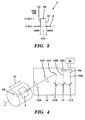
- Figure 3 illustrates a signal produced by a light detector (also known as a light sensor) 10A, depicted in Figure 4, in response to light spot 5 moving across plate 4 and groove 3A while holding the drum stationary.
- light source 9A and lenses 13A,B produce light spot 5 illuminating plate 4, the light is reflected off plate 4 toward light detector 10A which produces signal 7B in Figure 3.
- the light from source 9A is preferably applied generally normal (at about 90 degrees) to plate 4, groove 3A, and support surface 1B.
- a light beam is applied at about 7 degrees away from normal (e.g. at ⁇ 83 or ⁇ 97 degrees to the surface of the drum) as shown by angle 30 in figure 2.
- illuminating anti-reflective layer 6 almost all the light is absorbed by anti-reflective layer 6 in accordance with blackbody absorption theory as is well known.
- the side 7C of the signal illustrated in figure 3 corresponds to an exact edge 4A of plate 4.
- the change in voltage indicated at T1 or T2 in figure 3 represents an edge, e.g. 4A, of plate 4.
- Groove 3A extends across drum 1A from one end to the other end. As source 9A is scanned along groove 3A, two edges of plate 4 are detected and are shown in figure 3 as 7A and 7C.
- Light source 9A may be a laser, Light Emitting Diode (LED), incandescent, halogen, fluorescent or any other light source.
- Source 9A is fixedly mounted integral to a moveable assembly 14, which in turn is mounted proximate to support surface 1B.
- Moveable assembly 14 can be moved and controlled in the same manner as optic assemblies used to expose unimaged printing plates or film, as is well known in the art of making platesetters and imagesetters.
- Figure 4 shows a controller 31 interfacing with, and controlling assembly 14. Any wavelength light source may be used with the invention described herein.
- Light source 9A need not be coherent or collimated, may be monochromatic or have broadband spectra, and need not be in the visible range of wavelengths to the human eye. Any laser technology would be suitable such as a semiconductor laser, gas laser, dye laser, or solid state rod laser.
- a single source or a plurality of light sources combined into a single beam producing a single light spot 5 may also be employed.
- Reflectors 11A-C and beamsplitter 12 are used to facilitate compact packaging and to provide a reference signal to detector 10A (if detector 10A is a quadrant detector), also fixedly mounted integral to moveable assembly 14.
- Detector 10A may be a simple photodiode, phototransistor, photomultiplier tube or other light detection means.
- Light from light source 9A is focused with lenses 13A-B toward, and generally normal to, support surface 1B. Though a plurality of lenses 13A-B and reflectors 11A-B are shown in Figure 4, any number, or none may be used to practice the invention.
- Moveable assembly 14 moves across support surface 1B in a transverse direction shown by arrow 15 such that light spot 5 is continuously aligned with groove 3A. This continual alignment between light spot 5 and groove 3A may be accomplished by holding drum 1A stationary while source 9A is moved. Alternatively, moveable assembly 14 may have two degrees of freedom (e.g. the ability to move horizontally and vertically) so as to be able to follow groove 3A while drum 1A rotates.
- Light source 9A is preferably amplitude modulated with a sine wave to provide some rejection to background or stray light that may be incident upon the light sensor 10A, 10B.
- the modulation frequency in the preferred embodiment is approximately 100 KHz at about 80% depth of modulation, but is not limited to this frequency or modulation depth.
- Light source 9A may alternatively be operated in a continuous wave (CW) mode. Operating light source 9A in pulse mode is possible although synchronization of a light pulse with the alignment of light spot 5 over plate edge 4A is difficult. Further, as explained infra, precisely knowing the edge 4A of a plate 4 is critical to being able to detect small degrees of skew in a plate. Skew is a condition where a printing plate is mounted in a crooked manner, typically a lateral side being non-parallel to the end of the drum.
- CW continuous wave
- FIG. 5 An alternate embodiment is illustrated in Figure 5 where support surface 17B is of the internal drum configuration 17A shown with plate 4 mounted on internal drum 17A. Operation of the optical portion of the system and groove is similar as explained in the embodiments of Figures 1-4.
- An additional feature shown in Figure 5 is a second groove 18A formed into the surface 17B of internal drum 17A. Two or more spatially separated grooves having anti-reflective characteristics allow for detection of a skewed plate 4 mounted on a support surface.
- Figure 6 an alternate embodiment of an external drum 1B with two grooves 3A, 18B formed into said drum will be used to describe how a skewed plate is detected. The method to detect a skewed plate is independent of the type of support surface employed.
- Movable assembly 14 scans light spot 5 from end 1C of drum 1B, across groove 3A, until plate edge 4A is detected as shown by signal 7A in figure 3.
- the time, or alternatively, the distance from end 1C of the drum 1B, along groove 3A, to the edge 4A of plate 4 is recorded as X as shown in figure 6.
- Assembly 14 and drum 1B both move to re-position light spot 5 at said end 1C of drum 1B.
- Assembly 14 proceeds to scan light spot 5 across groove 18B, until plate edge 4A is again detected as shown by signal 7A in figure 3.
- the time, or alternatively, the distance from the end 1C of drum 1B to edge 4A of plate 4 is recorded as Y as shown in figure 6. If X and Y are not equal, then plate 4 is skewed.
- the direction of the skew can also be determined depending on whether X or Y is larger.
- the method for detecting a skewed plate is similar when the support surface is internal drum 17A.
- One difference being internal drums are typically stationary in the art. Consequently, moveable assembly 14 must be able to move spot 5 both laterally and vertically in contrast to external drum systems where rotation of the drum precludes the need for the assembly 14 to move vertically.
- the order of the steps outlined above for determining a skewed plate or finding an edge of a plate may be performed in other sequences e.g. a plate may be detected and then the groove.
- Figure 7 is an alternate embodiment showing light source 9B and light detector 10B as being co-located in moveable assembly 14, without the use of lenses, reflectors, or beamsplitters.
- Various configurations may be employed to exploit the invention herein ranging from simple to complex. The multitude of configurations demonstrates the utility and flexibility of the invention.
- the embodiments described herein have been shown to detect a side edge of a printing plate. In fact, the invention is equally applicable to detecting a leading or trailing (e.g. top or bottom edge) edge, or a plurality of edges, as may be required to suit a particular application.
- Figure 8 shows an embodiment with a plurality of diagonal grooves on an external drum. The techniques and methods described herein are also applicable to the embodiment of figure 8.
- Diagonal grooves may also be used on internal drums in a similar manner.
- Figures 9a-c illustrate unexpected test results obtained with the invention herein allowing very precise detection of edge 4A of imageable plate 4.
- the voltage levels 21 and 23 would not contain any noise, and rise and fall times 22A would be zero seconds.
- Sides or "skirts" 22A of the pulse in figure 9a would not contain any sharp discontinuities as edge 4A and side 20A of plate 4 would be perfectly orthogonal to the surface of plate 4.
- the expected waveform due to mechanical, electrical, optic, and fabrication errors is shown in figure 9b.
- FIG. 10a is a side view of groove 3A having a bottom surface 3C that is not mutually perpendicular with the two adjacent sides.
- the angles 31 and 32 are about 120 and 60 degrees respectively from each associated side.
- the purpose of the sloping bottom surface 3C of groove 3A is to redirect incident light, 28 and 29 originating from light source 9C away from a light sensor (not shown). Light rays 28 and 29 are redirected by the groove creating light patterns 28A and 29A respectively, as shown in figures 10a,b.
- Figure 10b is a view A-A of figure 10a looking toward light source 9C.
- Two patterns are created on either side of source 9C due to multiple reflections of light rays 28 and 29 as shown in figure 10a.
- a light sensor positioned in areas 30A or 30B as shown in figure 10b,d would not detect light from source 9C when source 9C illuminates the groove.
- source 9C illuminates plate 4 as shown in figures 10c,d
- a light pattern is created surrounding and encompassing source 9C.
- Light sensors placed adjacent source 9C for example in positions 30A or 30B, would now detect light indicating a plate is present.
- the antireflective material disclosed supra absorbs the incident light, rather than simply redirecting incident light in a desired direction either towards or away from a sensor.
- Many variations of the shape of groove 3 are possible that do not depart from the invention.
Landscapes
- Manufacture Or Reproduction Of Printing Formes (AREA)
- Exposure And Positioning Against Photoresist Photosensitive Materials (AREA)
- Length Measuring Devices By Optical Means (AREA)
- Inking, Control Or Cleaning Of Printing Machines (AREA)
Abstract
Description
- The invention is in the field of imaging systems for use in the printing industry. More particularly, the invention relates generally to the field of edge detection of imageable printing plates mounted in or on an internal or external drum platesetter used for imaging printing plates. The invention is also suitable for use in an imagesetter used for imaging a film media, which is thereafter used in the process to image a printing plate.
- A critical step in a process to transfer an image to a printing plate mounted on a platesetter, for subsequent use on a printing press, is obtaining precise alignment between the image and the plate. An image, e.g. a family portrait, can be skewed if it is not precisely aligned with the outer edges of the printing plate. To prevent skewing, the outer edges of the image should be aligned with the outer edges of the printing plate. Many printing presses have registration pins for installing the plate onto the press. Often the plate has a series of holes punched into it (i.e. a collinear array of holes at each end of the plate) so the plate may be placed over the registration pins on the press. This is done so as to duplicate the same precise alignment of the plate on the printing press as when the plate was exposed to the image on the platesetter. When holes are punched into the plate, precise alignment between the holes and the outer edges of the plate is also required.
- An alternate method of installing and aligning (known as registering) plates onto printing equipment e.g. platesetters, printing presses etc. is to simply place an outer edge of a plate up against the registration pins. The outer edges of the plate are then determined by various means and the image area defined with respect to the outer edges of the plate. Alignment errors are directly proportional to how accurately and how precisely edges of the plate can be determined. Various methods are employed to detect an edge of a plate. These methods include mechanical switches, optics, and various other electrical sensing techniques. Each technique has unique disadvantages. For example, mechanical switches cannot detect the edge of a plate with the same resolution that is used to create the image e.g. on the order of pixels. This limits the ability to maximize the available image area of the plate. Further, mechanical edge detection techniques can damage a portion of the plate.
Some optical techniques have been investigated, but can be limited for many reasons. For example, plates can be very thin, often on the order of 0.006 inches thick. This creates a difficult task of measuring the difference in round trip propagation time of a light pulse traveling to the plate and back versus the round trip propagation time of a light pulse traveling to the surface supporting the plate and back. The type of equipment supporting the plate also places limitations on optic techniques. Often the support surface is a metal drum, onto which the plate is mounted. The metal drum, opaque to light, makes an optic transmission method expensive to manufacture. A source must be positioned outside the drum, and a light detector placed in a recess formed in the surface of the drum. This technique is more difficult to implement on a rotating drum. Reflective methods employed by some workers rely on differences in contrast between different surfaces to reflect varying amounts of light.
Alternatively, attempting to rely on differences in projected focal area between different surfaces to reflect different amounts of light can be difficult. Consider that the amount of light reflected from a surface will vary depending on the size of the light spot (focal area) on the surface. A large spot, with lower light density, reflects less light toward a remote point, than a small spot with higher light density does. A thin plate mounted on a surface produces a very small difference in focal area (spot size) when the spot is on the plate verses the surface. Consequently, the difference in reflected light is very small and difficult to detect. The difference in reflected light is what makes detecting the edge of a plate possible. Large differences in the amount of reflected light between any two surfaces, simplify, or even eliminate the need for analog signal conditioning circuitry, and allow detection of very small physical discontinuities such as the edge of a thin plate. If the reflectivity between two surfaces is sufficiently different, a large difference in the amount of light reflected from each surface will result even though the physical difference in height is very small, or co-planar. An example is a piece of white paper next to a piece of black paper. The white paper reflects a large amount of light, where the black paper absorbs a large amount of light. Consequently, the black paper reflects less light compared to the white paper. The challenge is obtaining an adequate difference in reflectivity between a plate and a surface that supports the plate. When the difference in reflectivity between two surfaces is very small, e.g. between a black surface and a dark blue surface, it can be very difficult to determine a difference. The tiny difference is "smeared" and even often obscured by noise. Workers have experimented by coating a surface to reduce reflected light by painting the surface with black paint. This technique may be useful to detect a plate surface, if one is willing to accept the additional complexity to integrate the reflected signals over a period of time. This technique has not worked well to detect the precise edge of a plate. One reason is the very smooth black surface still reflects some light which manifests itself as noise in the light detector. This noise reduces the signal to noise ratio of the electrical signal which is proportional to the difference in reflected light between the plate and the surface. Other factors that contribute to lower Signal/Noise ratios (the difference between a signal and noise) are variations in the 1) reflectivity of printing plates due to different manufacturing processes used by different manufacturers, 2) reflectivity of the drum (or other support surface) due to different surface treatments and debris, 3) reflectivity of the drum (or other support surface) due to surface roughness, and 4) use of thin plates produces little change in light spot size. - A technique for detecting an edge of a printing plate, and any associated skew, is disclosed in co-pending U.S. patent applications Ser. No. 09/571,674 by Tice et al, and 09/573,638 by Wolber et al. Tice and Wolber employ a method of making a series of optical transmission measurements using a plurality of light sensors and light detectors. Edge detection sensors according to Tice et al and Wolber et al are not implemented on a drum, but in the loading and/or unloading paths to and from a drum.
- An edge detection system employed on a non-rotating internal drum imaging systems is described in U.S. Patents 5,889,547 to Rombult et al, and U.S. Patent 6,097,475 to Jakul. Both patents describe a light detector recessed into an imaging drum for making a transmission measurement. Such a configuration is unsuitable for an external drum imaging system since an external drum rotates and would require slip rings to carry electrical signals to and from the drum.
What is needed, is a method to further reduce the amount of light reflected from an external drum or other support surface.
Further, the mechanical integrity of the edges of the plate must
not be compromised and the edges must remain co-planer with the other portions of the plate e.g. not curled up or bowed down. Further, since the plate is often mounted in a stationary position, edge detection apparatus must be capable of moving with respect to the stationary plate. - It is an object of the invention herein to provide a reliable method and apparatus for precisely detecting an edge of an imageable printing plate or other imageble media mounted on a drum or other support surface of an internal or external drum imagesetter or platesetter.
It is a further object of the invention herein to increase the focal area (spot size) of a light beam by using at least one groove formed into a drum or other support surface where said focal area (spot) is inside of said groove so the amount of light reflected from a surface is reduced. - It is another object of the invention herein to decrease the amount of light reflected from a drum or other support surface using a groove formed into a drum or other support surface where the groove has anti-reflecting (light absorbing) layer deposed on an inside surface of said groove.
- It is another object of the invention herein to use a specially shaped groove formed into a support surface of a drum to redirect light originating from a light source away from a light sensor responsive to light from said light source.
- It is another object of the invention herein to provide a method for detecting a skewed plate or other imageable media mounted on a support surface of a drum.
The above-mentioned advantageous effects are realised by a system having the specific features set out in claim 1 and by a method having the specific features set out inclaim 12. Specific features for preferred embodiments of the invention are set out in the dependent claims.
Further advantages and embodiments of the present invention will become apparent from the following description and drawings. - The following description may be further understood with reference to the accompanying drawings in which:
- Figure 1 shows an imageable printing plate mounted on an external drum support surface having a groove illuminated with a light beam in accordance with one embodiment of the invention.
- Figure 2 shows an imageable plate mounted on a support surface of an external drum with an anti-reflective layer deposed on an inside surface of a groove and a light beam traveling along said groove in accordance with the invention.
- Figure 3 is a drawing of an electrical signal from a light detector detecting reflected light in accordance with the invention.
- Figure 4 shows one embodiment of a light source and light detector mounted in a moveable assembly in accordance with the invention.
- Figure 5 shows an imageable plate mounted on a portion of an internal drum with a plurality of grooves in accordance with the invention.
- Figure 6 is an alternate embodiment of an imageable plate mounted on an external drum with a plurality of anti-reflective grooves for detecting a skewed plate.
- Figure 7 shows alternate embodiment of the system of Figure 4.
- Figure 8 is an alternate embodiment of the system of Figure 1 showing at least one helical or diagonal groove.
- Figures 9a-c show test results demonstrating utility of the invention for precise edge detection of an imageable plate.
- Figures 10a-10d show an alternate embodiment of the groove of Figure 2 for redirecting light away from a light sensor.
-
- The drawings are shown for illustrative purposes only, and are not to scale.
- The invention described herein is implemented on machines for transferring an electronic image to an imageable media (referred to as imaging) such as a printing plate or film. Two general types of machines are those having a rotatable external drum and those having a non-rotatable internal drum. In both cases, the drums are used to support the media to be imaged. The media is supported on the outside surface in the case of an external drum machine. The media is supported on the inside surface of an internal drum machine. In both cases, a moveable light source is moved with respect to the media in order to image the media.
One embodiment of the invention is generally illustrated in Figure 1 showing a first anti-reflective (light absorbing)groove 3A formed into asupport surface 1B of anexternal drum 1A. Also shown in Figure 1 is animageable plate 4 mounted on asurface 1B ofexternal drum 1A.Groove 3A is preferably formed parallel to thelongitudinal axis 2 of the drum also known as the axial direction or spin axis of the drum. Withgroove 3A parallel to drumaxis 2, anedge 4A ofplate 4 is generally perpendicular to groove 3A whenplate 4 is properly mounted.Groove 3A cannot be parallel to and positioned under,edge 4A ofplate 4 asedge 4A may sag intogroove 3A, or may otherwise be damaged bygroove 3A, making precise detection ofedge 4A unreliable, and near impossible. Further,groove 3A cannot be too wide for the same reasons supra. Formost plates groove 3A is preferably less than about 2mm wide, with some plates requiring a groove between about 1-1.5mm. The limit on the minimum width ofgroove 3A is imposed by the ability to manufacture the narrow groove. The invention herein does not place a limitation on how narrow a groove can be used.
The depth of thegroove 3A need be only slightly more than the height of an anti-reflective layer deposed on the inside of the groove. This allows the anti-reflective layer to be completely recessed precluding contact between the plate and the anti-reflective layer. An alternate embodiment includes a groove that may be considerably deeper if an anti-reflective layer is not used, and the shape and/or depth of the groove is used to prevent light from alight source 9A from illuminating alight sensor 10A as disclosed infra .
A spot oflight 5, produced bylight source 9A depicted in figure 4, is shown illuminating a portion ofplate 4 that is positioned directly overgroove 3A.Light spot 5 fromlight source 9A is aligned with, and is moved along,groove 3A whiledrum 1A is held stationary. Figure 2 illustrates a positional relationship betweenplate 4,support surface 1B,groove 3A andlight spot 5 on a larger scale.
Also shown in Figure 2 is ananti-reflective layer 6 deposed on an inside surface ofgroove 3A for minimizing the amount of reflected light whenspot 5 illuminates groove 3A. Said anti-reflective layer approximates an infinite optical path length. An infinite optical path is defined as a path that does not reflect light toward a light detector. In contrast,plate 4 reflects a large amount of light.
By increasing the difference in the reflected light between the plate and the surface of the drum, the S/N ratio will be increased thereby preventing "smearing" of the signal and allowing detection of the exact edge of a printing plate.
Anti-reflective layer 6 may include, but is not limited to, black velvet, black paint, black oxide coating, black cloth/plush material, black polymer or any other material that absorbs all, or essentially all of the light fromsource 9A that is incident upon said anti-reflective layer. Alternatively,anti-reflective layer 6 may be any material having a chromophore (or color) whose peak absorbance wavelength is matched to the wavelength of opticlight source 9A so essentially all of the light fromsource 9A is absorbed.
Figure 3 illustrates a signal produced by a light detector (also known as a light sensor) 10A, depicted in Figure 4, in response tolight spot 5 moving acrossplate 4 and groove 3A while holding the drum stationary. Referring to Figures 1-4, whenlight source 9A andlenses 13A,B producelight spot 5 illuminatingplate 4, the light is reflected offplate 4 towardlight detector 10A which producessignal 7B in Figure 3. The light fromsource 9A is preferably applied generally normal (at about 90 degrees) toplate 4,groove 3A, andsupport surface 1B. In the preferred embodiment, a light beam is applied at about 7 degrees away from normal (e.g. at ∼83 or ∼97 degrees to the surface of the drum) as shown byangle 30 in figure 2. Aslight spot 5 moves from the plate, and entersgroove 3A, illuminatinganti-reflective layer 6, almost all the light is absorbed byanti-reflective layer 6 in accordance with blackbody absorption theory as is well known. Consequently, essentially no light fromsource 9A is reflected byanti-reflective layer 6 towarddetector 10A resulting insignal 8 of Figure 3 being produced bydetector 10A.
Theside 7C of the signal illustrated in figure 3 corresponds to anexact edge 4A ofplate 4. In other words, the change in voltage indicated at T1 or T2 in figure 3, represents an edge, e.g. 4A, ofplate 4.
The quality, e.g. how "clean" theedge 7C (in addition tosignals 7B and 8) is, affects how precisely edge 4A can be defined usingsignal 7.Groove 3A extends acrossdrum 1A from one end to the other end. Assource 9A is scanned alonggroove 3A, two edges ofplate 4 are detected and are shown in figure 3 as 7A and 7C. - Referring to Figure 4, operation of one embodiment of a system using the technique described supra will be described.
Light source 9A, may be a laser, Light Emitting Diode (LED), incandescent, halogen, fluorescent or any other light source.Source 9A is fixedly mounted integral to amoveable assembly 14, which in turn is mounted proximate to supportsurface 1B.
Moveable assembly 14 can be moved and controlled in the same manner as optic assemblies used to expose unimaged printing plates or film, as is well known in the art of making platesetters and imagesetters. Figure 4 shows acontroller 31 interfacing with, and controllingassembly 14.
Any wavelength light source may be used with the invention described herein. Use of a light source having a wavelength equal to a wavelength used to transfer an image to a photosensitive plate, e.g. writing on the plate, is also possible. However, the energy used to expose the plate must be different from the energy used to locate an edge of the plate. For example, the fluence or output power used to locate an edge, must be less than the power or fluence required to transfer an image to the plate in order to avoid "burning" an unwanted artifact onto the plate.
Light source 9A need not be coherent or collimated, may be monochromatic or have broadband spectra, and need not be in the visible range of wavelengths to the human eye. Any laser technology would be suitable such as a semiconductor laser, gas laser, dye laser, or solid state rod laser. The only limitations being cost, size, complexity, and power requirements. A single source or a plurality of light sources combined into a single beam producing a singlelight spot 5 may also be employed.Reflectors 11A-C andbeamsplitter 12 are used to facilitate compact packaging and to provide a reference signal todetector 10A (ifdetector 10A is a quadrant detector), also fixedly mounted integral tomoveable assembly 14.
Detector 10A may be a simple photodiode, phototransistor, photomultiplier tube or other light detection means. Light fromlight source 9A is focused withlenses 13A-B toward, and generally normal to,support surface 1B. Though a plurality oflenses 13A-B andreflectors 11A-B are shown in Figure 4, any number, or none may be used to practice the invention.Moveable assembly 14 moves acrosssupport surface 1B in a transverse direction shown byarrow 15 such thatlight spot 5 is continuously aligned withgroove 3A. This continual alignment betweenlight spot 5 and groove 3A may be accomplished by holdingdrum 1A stationary whilesource 9A is moved. Alternatively,moveable assembly 14 may have two degrees of freedom (e.g. the ability to move horizontally and vertically) so as to be able to followgroove 3A whiledrum 1A rotates.
Light source 9A is preferably amplitude modulated with a sine wave to provide some rejection to background or stray light that may be incident upon thelight sensor Light source 9A may alternatively be operated in a continuous wave (CW) mode. Operatinglight source 9A in pulse mode is possible although synchronization of a light pulse with the alignment oflight spot 5 overplate edge 4A is difficult.
Further, as explained infra, precisely knowing theedge 4A of aplate 4 is critical to being able to detect small degrees of skew in a plate. Skew is a condition where a printing plate is mounted in a crooked manner, typically a lateral side being non-parallel to the end of the drum. - An alternate embodiment is illustrated in Figure 5 where
support surface 17B is of theinternal drum configuration 17A shown withplate 4 mounted oninternal drum 17A. Operation of the optical portion of the system and groove is similar as explained in the embodiments of Figures 1-4. An additional feature shown in Figure 5 is a second groove 18A formed into thesurface 17B ofinternal drum 17A. Two or more spatially separated grooves having anti-reflective characteristics allow for detection of askewed plate 4 mounted on a support surface. Figure 6, an alternate embodiment of anexternal drum 1B with twogrooves Movable assembly 14 scanslight spot 5 fromend 1C ofdrum 1B, acrossgroove 3A, untilplate edge 4A is detected as shown bysignal 7A in figure 3. The time, or alternatively, the distance fromend 1C of thedrum 1B, alonggroove 3A, to theedge 4A ofplate 4 is recorded as X as shown in figure 6.Assembly 14 anddrum 1B both move to re-positionlight spot 5 at saidend 1C ofdrum 1B.Assembly 14 proceeds to scanlight spot 5 acrossgroove 18B, untilplate edge 4A is again detected as shown bysignal 7A in figure 3. The time, or alternatively, the distance from theend 1C ofdrum 1B to edge 4A ofplate 4 is recorded as Y as shown in figure 6. If X and Y are not equal, thenplate 4 is skewed. The direction of the skew can also be determined depending on whether X or Y is larger. The method for detecting a skewed plate is similar when the support surface isinternal drum 17A. One difference being internal drums are typically stationary in the art. Consequently,moveable assembly 14 must be able to movespot 5 both laterally and vertically in contrast to external drum systems where rotation of the drum precludes the need for theassembly 14 to move vertically. Further, the order of the steps outlined above for determining a skewed plate or finding an edge of a plate may be performed in other sequences e.g. a plate may be detected and then the groove.
Figure 7 is an alternate embodiment showinglight source 9B andlight detector 10B as being co-located inmoveable assembly 14, without the use of lenses, reflectors, or beamsplitters. Various configurations may be employed to exploit the invention herein ranging from simple to complex. The multitude of configurations demonstrates the utility and flexibility of the invention. Further, the embodiments described herein have been shown to detect a side edge of a printing plate. In fact, the invention is equally applicable to detecting a leading or trailing (e.g. top or bottom edge) edge, or a plurality of edges, as may be required to suit a particular application.
Figure 8 shows an embodiment with a plurality of diagonal grooves on an external drum. The techniques and methods described herein are also applicable to the embodiment of figure 8. Diagonal grooves may also be used on internal drums in a similar manner.
Figures 9a-c illustrate unexpected test results obtained with the invention herein allowing very precise detection ofedge 4A ofimageable plate 4. Aslight source 9A anddetector 10B are scanned alonggroove 3A andplate 4 bymoveable assembly 14, an ideal response shown in figure 9a is desired. Thevoltage levels fall times 22A would be zero seconds. Sides or "skirts" 22A of the pulse in figure 9a would not contain any sharp discontinuities asedge 4A andside 20A ofplate 4 would be perfectly orthogonal to the surface ofplate 4.
The expected waveform due to mechanical, electrical, optic, and fabrication errors is shown in figure 9b.Imperfections 20B in the side and edge ofplate 4 were predicted to cause multiple reflections resulting in long rise andfall times 26, andsharp discontinuities 27 making the detection of the exact edge of the plate very difficult.
Experiments have shown the results to be better than expected as illustrated in figure 9c. Of particular interest in figure 9c is the lack ofsharp discontinuities 27 shown in figure 9b. Withoutsharp discontinuities 27 in the signal, ambiguity in determining theexact edge 4A of theplate 4 can be avoided.
An alternate embodiment of the invention is shown in Figures 10a-10d. Figure 10a is a side view ofgroove 3A having abottom surface 3C that is not mutually perpendicular with the two adjacent sides. Theangles sloping bottom surface 3C ofgroove 3A is to redirect incident light, 28 and 29 originating fromlight source 9C away from a light sensor (not shown). Light rays 28 and 29 are redirected by the groove creatinglight patterns - Figure 10b is a view A-A of figure 10a looking toward
light source 9C. Two patterns are created on either side ofsource 9C due to multiple reflections oflight rays areas source 9C whensource 9C illuminates the groove. However, whensource 9C illuminatesplate 4 as shown in figures 10c,d, a light pattern is created surrounding and encompassingsource 9C. Light sensors placedadjacent source 9C, for example inpositions
Many variations of the shape of groove 3 are possible that do not depart from the invention. - In accordance with the provisions of the patent laws and jurisprudence, exemplary configurations described above are considered to represent a preferred embodiment of the invention. However, it should be noted that the invention may be practiced in a variety of configurations other than as specifically illustrated and described without departing from its scope.
Claims (13)
- A system for detecting an edge (4A) of a plate (4) on a support (1A,17B) for imaging the plate (4), the system comprising:a support surface (1B) for supporting said plate (4);a moveable assembly (14) comprising:i) a light source (9A) for directing light to said surface (1B); andii) a light sensor (10A) for detecting reflected light originating from said light source (9A); andat least one groove (3A) into said surface (1B) for preventing light from said light source (9A), from being directed towards said light sensor (10A).
- The system of claim 1 wherein said light source (9A) is for directing a beam of light toward said surface (1B) at an angle between about 83 degrees and 90 degrees with respect to said surface (1B).
- The system according to claim 1 or 2 wherein said surface (1B) is an internal surface or an external surface of a drum (1A) and at least one groove (3A) is parallel to a longitudinal axis (2) of said drum (1A).
- The system according to any one of claims 1 to 3 wherein a cross sectional shape of said at least one groove (3A) is generally rectangular, preferably square.
- The system according to any one of the previous claims wherein the width of said at least one groove (3A) is between 1 mm and 2 mm.
- The system according to any one of the previous claims wherein said at least one groove (3A) further comprises an antireflective layer (6) deposed on at least a portion of an inside surface of said at least one groove (3A) for reducing the amount of light reflected from the inside of said at least one groove (3A).
- The system according to claim 6 wherein said antireflective layer (6) is selected from the group consisting of black velvet, black plush, black cloth, black paint, a black polymer, a chromophore having a peak absorption wavelength substantially the same as said light source, and black oxide.
- The system according to any one of the previous claims wherein said at least one groove (3A) extends along the entire length of the portion of said surface (1B) operative to support said plate (4).
- The system according to any one of the previous claims wherein said at least one groove (3A) has a geometric cross section for directing light from said source (9C), that is incident upon said at least one groove (3A), away from said light sensor (30A,30B), wherein said groove (3A) preferably has a bottom surface (3C) positionedat an angle of about 120 degrees from a first side of said groove (3A)at an angle of about 60 degrees from a second side of said groove (3A).
- The system according to any one of the previous claims, wherein two grooves (1C,19) are formed diagonally across said surface (1B) for detecting a skewed plate (4).
- The system according to any one of the previous claims wherein said light sensor (10A) is for providing an electrical signal (7A,7B,7C,8) having at least two different voltage levels (7B,8)corresponding todetected light reflected from said plate (4); and,light reflected from said groove (3A).
- A method for detecting an edge of a plate (4) on a support surface (1B) for imaging said plate (4), the method comprising:providing a moveable assembly (14) having:i) a light source (9A); and,ii) a light sensor (10A) responsive to light from said light source (9A);providing a groove (3A) formed into said support surface (1B), said groove (3A) having an anti-reflective layer (6) deposed on an inside surface of said groove (3A);illuminating a portion of said groove (3A) with light from the light source (9A), said light applied generally normal to said groove (3A);detecting an absence of said light reflected from said groove (3A);said absence of reflected light from said groove (3A) corresponding to a first signal level (8) generated by said light sensor (10A);moving said light source (9A) along said groove (3A);detecting light reflected from the plate (4) mounted over a portion of said groove (3A) in response to said light from said light source (9A) illuminating a portion of the plate (4) as said light source (9A) passes over the plate (4);said reflected light corresponding to a second signal level (7B) generated by said light sensor (10A); andsaid edge of the plate (4) being detected when a difference between said first (8) and said second (7B) signal levels exceed a predetermined value.
- The method according to claim 12 for detecting a skewed plate (4) on said support surface (1B) comprising the steps of:moving said moveable assembly (14) along a path parallel to said first groove (3A) while monitoring a first spatial position (1C) of said light source (9A);recording a first position (X) of said moveable light source (9A) when a first difference between said first (8) and said second (7B) signal levels exceeds a first predetermined value;positioning said moveable assembly (14) at said first spatial position over a second groove (18B) into said surface (1B), said second groove (18B) formed parallel to said first groove (3A);illuminating a portion of said second groove (18B) with said beam of light from said moveable light source (9B), said light beam applied generally normal to said second groove (18B);detecting an absence of light reflected from said second groove (18B);said absence of reflected light from said second groove (18B) corresponding to a third signal level generated by said light sensor (10A);moving said moveable assembly (14) along a path parallel to said second groove (18B) while monitoring a second spatial position (1C) of said light source (9B);detecting light reflected from said plate (4) located over a portion of said second groove (18B) in response to said beam of light from said light source (9B) illuminating said plate (4) as said light source (9B) passes over said plate;said reflected light from said plate (4) corresponding to a fourth signal level generated by said light sensor (10A) ;recording a second position (Y) of said moveable light source (9B) when a second difference between said third and said fourth signal levels exceeds a second predetermined value; and,calculating a third difference between said first position (X) and said second position (Y) and determining if said third difference exceeds a third predetermined value indicating a skewed plate (4) is located on said surface.
Applications Claiming Priority (2)
| Application Number | Priority Date | Filing Date | Title |
|---|---|---|---|
| US4093 | 2001-10-23 | ||
| US10/004,093 US6815702B2 (en) | 2001-10-23 | 2001-10-23 | Method and apparatus for detection of an edge of a printing plate mounted on a drum imaging system |
Publications (3)
| Publication Number | Publication Date |
|---|---|
| EP1306213A2 true EP1306213A2 (en) | 2003-05-02 |
| EP1306213A3 EP1306213A3 (en) | 2004-01-21 |
| EP1306213B1 EP1306213B1 (en) | 2011-04-13 |
Family
ID=21709097
Family Applications (1)
| Application Number | Title | Priority Date | Filing Date |
|---|---|---|---|
| EP02102441A Expired - Lifetime EP1306213B1 (en) | 2001-10-23 | 2002-10-15 | Method and apparatus for detection of an edge of a printing plate mounted on a drum imaging system |
Country Status (4)
| Country | Link |
|---|---|
| US (1) | US6815702B2 (en) |
| EP (1) | EP1306213B1 (en) |
| JP (1) | JP2003202677A (en) |
| DE (1) | DE60239722D1 (en) |
Cited By (1)
| Publication number | Priority date | Publication date | Assignee | Title |
|---|---|---|---|---|
| EP1543966A1 (en) * | 2003-12-19 | 2005-06-22 | Creo Inc. | Method and apparatus for detecting the seam of a flexographic printing plate precursor |
Families Citing this family (22)
| Publication number | Priority date | Publication date | Assignee | Title |
|---|---|---|---|---|
| DE10066062A1 (en) * | 2000-08-04 | 2004-05-27 | Sca Hygiene Products Gmbh | Separating and / or perforating device |
| US7456379B2 (en) * | 2003-02-03 | 2008-11-25 | Kodak Graphic Communications Canada Company | Printing plate registration and optical alignment device including locating at least a part of a reference edge in at least one digital camera image |
| US6968782B2 (en) * | 2003-02-03 | 2005-11-29 | Creo Inc. | Printing plate registration and imaging |
| DE10306104B4 (en) * | 2003-02-14 | 2005-03-24 | Heidelberger Druckmaschinen Ag | Apparatus and method for detecting the edge of a recording material |
| DE10307381B3 (en) * | 2003-02-21 | 2004-06-03 | Heidelberger Druckmaschinen Ag | Printing plate recording device with pivoted sensor finger for detecting edge of printing plate incorporated in surface of printing plate exposure drum |
| JP4573567B2 (en) * | 2004-04-27 | 2010-11-04 | 大日本スクリーン製造株式会社 | Image recording device |
| KR100612451B1 (en) * | 2004-10-16 | 2006-08-16 | 삼성전자주식회사 | Print media recognition apparatus of image forming apparatus and method thereof |
| TWI244320B (en) * | 2004-10-20 | 2005-11-21 | Asia Optical Co Inc | Scanning unit having anti-reflective layers with high reflectivity |
| US7398732B2 (en) * | 2005-09-08 | 2008-07-15 | Agfa Corporation | Method for determining an image area to be exposed on a printing plate |
| US7854199B2 (en) * | 2007-03-29 | 2010-12-21 | Eastman Kodak Company | Printing plate registration using a camera |
| US20080245981A1 (en) * | 2007-04-05 | 2008-10-09 | Hebert Thomas K | Apparatus and method for edge detection |
| US7784402B2 (en) * | 2007-04-24 | 2010-08-31 | Eastman Kodak Company | Method for loading printing plate on imaging device |
| US7893416B2 (en) * | 2008-09-17 | 2011-02-22 | Eastman Kodak Company | Detecting printing plate edge alignment |
| US7989788B2 (en) * | 2008-12-03 | 2011-08-02 | Eastman Kodak Company | Determining position of a media page using a slot in the imaging drum |
| US8146498B2 (en) * | 2008-12-03 | 2012-04-03 | Eastman Kodak Company | Printing plate registration |
| WO2011044240A1 (en) * | 2009-10-06 | 2011-04-14 | The Curators Of The University Of Missouri | External/internal optical adapter with biased photodiodes for ftir spectrophotometer |
| US8950326B1 (en) | 2012-04-19 | 2015-02-10 | Laser Dot Holding B.V. | Method and apparatus for laser ablating an image on a mounted blank printing plate |
| US10261028B2 (en) * | 2016-02-10 | 2019-04-16 | Carl Zeiss Industrial Metrology, Llc | Device for optically inspecting a surface of a sample |
| JP6718793B2 (en) * | 2016-10-26 | 2020-07-08 | 株式会社Screenホールディングス | Image recording apparatus and image recording method |
| CN112666802B (en) * | 2020-12-31 | 2023-02-10 | 江苏友迪电气有限公司 | Plate specification detection method and device |
| US20230164279A1 (en) * | 2021-11-22 | 2023-05-25 | J.Morita Manufacturing Corporation | Reading apparatus |
| CN114963978B (en) * | 2022-05-05 | 2025-02-11 | 超美斯新材料股份有限公司 | A method and control device for detecting bow degree of aramid paper |
Citations (2)
| Publication number | Priority date | Publication date | Assignee | Title |
|---|---|---|---|---|
| US5889547A (en) | 1997-06-04 | 1999-03-30 | Bayer Corporation -- Agfa Division | Registration detection apparatus for imaging systems |
| US6097475A (en) | 1997-08-21 | 2000-08-01 | Agfa Corporation | Method and apparatus for orienting a recording media sheet on a support surface |
Family Cites Families (11)
| Publication number | Priority date | Publication date | Assignee | Title |
|---|---|---|---|---|
| US4687943A (en) * | 1985-01-18 | 1987-08-18 | Research Technology International | Optical motion picture film inspection system |
| JPS63157087A (en) | 1986-12-19 | 1988-06-30 | Dainippon Screen Mfg Co Ltd | Photosensitive material detecting device and photosensitive material detecting method using same |
| DE3732934A1 (en) * | 1987-09-30 | 1989-04-20 | Heidelberger Druckmasch Ag | SENSOR DEVICE |
| JPH03165569A (en) * | 1989-11-24 | 1991-07-17 | Nippon Sheet Glass Co Ltd | Image transmission element and manufacture thereof |
| US6130702A (en) * | 1995-07-28 | 2000-10-10 | Creo Products Inc. | Method for reliable loading of unexposed printing plates |
| DE19854845B4 (en) * | 1998-01-30 | 2011-02-24 | Heidelberger Druckmaschinen Ag | Method and device for automatic detection of at least one printing plate edge |
| US6469808B1 (en) * | 1998-05-15 | 2002-10-22 | Rohm Co., Ltd. | Image reading apparatus and illuminator used for the same |
| DE19926848A1 (en) * | 1999-06-13 | 2000-01-20 | Stephan Joerg | Edge position sensing of continuously moving fabric line by infrared light uses transverse line of emitters and receivers and deduces edge position from integrated value of reflected light |
| JP2001059720A (en) * | 1999-08-23 | 2001-03-06 | Fuji Photo Film Co Ltd | Sheet material inspection device |
| IL131671A0 (en) * | 1999-08-31 | 2001-01-28 | Scitex Corp Ltd | Apparatus and method for edge detection |
| DE10136871A1 (en) * | 2001-07-28 | 2003-02-06 | Koenig & Bauer Ag | Device for detecting the position of an edge of a material to be processed |
-
2001
- 2001-10-23 US US10/004,093 patent/US6815702B2/en not_active Expired - Fee Related
-
2002
- 2002-10-15 EP EP02102441A patent/EP1306213B1/en not_active Expired - Lifetime
- 2002-10-15 DE DE60239722T patent/DE60239722D1/en not_active Expired - Lifetime
- 2002-10-16 JP JP2002301802A patent/JP2003202677A/en active Pending
Patent Citations (2)
| Publication number | Priority date | Publication date | Assignee | Title |
|---|---|---|---|---|
| US5889547A (en) | 1997-06-04 | 1999-03-30 | Bayer Corporation -- Agfa Division | Registration detection apparatus for imaging systems |
| US6097475A (en) | 1997-08-21 | 2000-08-01 | Agfa Corporation | Method and apparatus for orienting a recording media sheet on a support surface |
Cited By (1)
| Publication number | Priority date | Publication date | Assignee | Title |
|---|---|---|---|---|
| EP1543966A1 (en) * | 2003-12-19 | 2005-06-22 | Creo Inc. | Method and apparatus for detecting the seam of a flexographic printing plate precursor |
Also Published As
| Publication number | Publication date |
|---|---|
| DE60239722D1 (en) | 2011-05-26 |
| US20030075696A1 (en) | 2003-04-24 |
| EP1306213A3 (en) | 2004-01-21 |
| JP2003202677A (en) | 2003-07-18 |
| EP1306213B1 (en) | 2011-04-13 |
| US6815702B2 (en) | 2004-11-09 |
Similar Documents
| Publication | Publication Date | Title |
|---|---|---|
| EP1306213B1 (en) | Method and apparatus for detection of an edge of a printing plate mounted on a drum imaging system | |
| US4727419A (en) | Method and apparatus for detecting tire information mark | |
| KR100898963B1 (en) | Inspection system for two-dimensional imaging with line light spots | |
| US5068912A (en) | Track gauges for aligning and focussing the imaging system in a high speed document handling system | |
| CA2505017C (en) | Synchronous optical measurement and inspection method and means | |
| KR20050056924A (en) | Spot grid array imaging system | |
| GB2065301A (en) | Apparatus to measure properties of a moving sheet with standardization means | |
| US8614798B2 (en) | Pattern generators, calibration systems and methods for patterning workpieces | |
| JP2023541838A (en) | Exposure control in photolithographic direct exposure processes for circuit board or circuit manufacturing | |
| US20080245981A1 (en) | Apparatus and method for edge detection | |
| EP1081458A2 (en) | Apparatus and method for edge detection | |
| CA2034017C (en) | Scanning device for optically scanning a surface along a line | |
| JP2004252458A (en) | Apparatus and method for detecting edge of recording material | |
| JP4033781B2 (en) | Optical object identification device, processing system, and conveyance processing system | |
| JP2633718B2 (en) | Shape recognition device | |
| JP2006003168A (en) | Method and apparatus for measuring surface shape | |
| JP5285530B2 (en) | Film formation unevenness inspection device | |
| JP2001004326A (en) | Apparatus and method for inspecting side edges of sheet material | |
| JP2004230722A (en) | Image forming device | |
| JP2001050905A (en) | Cylindrical defect inspection equipment | |
| KR0138313B1 (en) | Non-contact height measuring device using laser | |
| JP3313985B2 (en) | Laser beam measuring device | |
| JP4176320B2 (en) | Scanning optical system beam measuring apparatus and method | |
| KR100327038B1 (en) | Wafer alignment apparatus | |
| JP4048163B2 (en) | Optical object identification device and printing apparatus using the same |
Legal Events
| Date | Code | Title | Description |
|---|---|---|---|
| PUAI | Public reference made under article 153(3) epc to a published international application that has entered the european phase |
Free format text: ORIGINAL CODE: 0009012 |
|
| AK | Designated contracting states |
Designated state(s): AT BE BG CH CY CZ DE DK EE ES FI FR GB GR IE IT LI LU MC NL PT SE SK TR |
|
| AX | Request for extension of the european patent |
Extension state: AL LT LV MK RO SI |
|
| PUAL | Search report despatched |
Free format text: ORIGINAL CODE: 0009013 |
|
| AK | Designated contracting states |
Kind code of ref document: A3 Designated state(s): AT BE BG CH CY CZ DE DK EE ES FI FR GB GR IE IT LI LU MC NL PT SE SK TR |
|
| AX | Request for extension of the european patent |
Extension state: AL LT LV MK RO SI |
|
| RIC1 | Information provided on ipc code assigned before grant |
Ipc: 7B 41C 1/00 B Ipc: 7G 01B 11/02 B Ipc: 7B 41F 27/00 A |
|
| 17P | Request for examination filed |
Effective date: 20040721 |
|
| AKX | Designation fees paid |
Designated state(s): DE FR GB |
|
| 17Q | First examination report despatched |
Effective date: 20090519 |
|
| GRAP | Despatch of communication of intention to grant a patent |
Free format text: ORIGINAL CODE: EPIDOSNIGR1 |
|
| GRAS | Grant fee paid |
Free format text: ORIGINAL CODE: EPIDOSNIGR3 |
|
| GRAJ | Information related to disapproval of communication of intention to grant by the applicant or resumption of examination proceedings by the epo deleted |
Free format text: ORIGINAL CODE: EPIDOSDIGR1 |
|
| GRAP | Despatch of communication of intention to grant a patent |
Free format text: ORIGINAL CODE: EPIDOSNIGR1 |
|
| GRAS | Grant fee paid |
Free format text: ORIGINAL CODE: EPIDOSNIGR3 |
|
| GRAA | (expected) grant |
Free format text: ORIGINAL CODE: 0009210 |
|
| AK | Designated contracting states |
Kind code of ref document: B1 Designated state(s): DE FR GB |
|
| REG | Reference to a national code |
Ref country code: GB Ref legal event code: FG4D |
|
| REF | Corresponds to: |
Ref document number: 60239722 Country of ref document: DE Date of ref document: 20110526 Kind code of ref document: P |
|
| REG | Reference to a national code |
Ref country code: DE Ref legal event code: R096 Ref document number: 60239722 Country of ref document: DE Effective date: 20110526 |
|
| PGFP | Annual fee paid to national office [announced via postgrant information from national office to epo] |
Ref country code: FR Payment date: 20110829 Year of fee payment: 10 Ref country code: GB Payment date: 20110822 Year of fee payment: 10 |
|
| PLBE | No opposition filed within time limit |
Free format text: ORIGINAL CODE: 0009261 |
|
| STAA | Information on the status of an ep patent application or granted ep patent |
Free format text: STATUS: NO OPPOSITION FILED WITHIN TIME LIMIT |
|
| 26N | No opposition filed |
Effective date: 20120116 |
|
| REG | Reference to a national code |
Ref country code: DE Ref legal event code: R097 Ref document number: 60239722 Country of ref document: DE Effective date: 20120116 |
|
| PGFP | Annual fee paid to national office [announced via postgrant information from national office to epo] |
Ref country code: DE Payment date: 20110822 Year of fee payment: 10 |
|
| GBPC | Gb: european patent ceased through non-payment of renewal fee |
Effective date: 20121015 |
|
| REG | Reference to a national code |
Ref country code: FR Ref legal event code: ST Effective date: 20130628 |
|
| PG25 | Lapsed in a contracting state [announced via postgrant information from national office to epo] |
Ref country code: GB Free format text: LAPSE BECAUSE OF NON-PAYMENT OF DUE FEES Effective date: 20121015 Ref country code: DE Free format text: LAPSE BECAUSE OF NON-PAYMENT OF DUE FEES Effective date: 20130501 |
|
| REG | Reference to a national code |
Ref country code: DE Ref legal event code: R119 Ref document number: 60239722 Country of ref document: DE Effective date: 20130501 |
|
| PG25 | Lapsed in a contracting state [announced via postgrant information from national office to epo] |
Ref country code: FR Free format text: LAPSE BECAUSE OF NON-PAYMENT OF DUE FEES Effective date: 20121031 |