EP1306027B1 - Pull of a slider for a slide fastener - Google Patents
Pull of a slider for a slide fastener Download PDFInfo
- Publication number
- EP1306027B1 EP1306027B1 EP02022628A EP02022628A EP1306027B1 EP 1306027 B1 EP1306027 B1 EP 1306027B1 EP 02022628 A EP02022628 A EP 02022628A EP 02022628 A EP02022628 A EP 02022628A EP 1306027 B1 EP1306027 B1 EP 1306027B1
- Authority
- EP
- European Patent Office
- Prior art keywords
- pull
- slider
- pin
- main body
- connecting ring
- Prior art date
- Legal status (The legal status is an assumption and is not a legal conclusion. Google has not performed a legal analysis and makes no representation as to the accuracy of the status listed.)
- Expired - Fee Related
Links
Images


Classifications
-
- A—HUMAN NECESSITIES
- A44—HABERDASHERY; JEWELLERY
- A44B—BUTTONS, PINS, BUCKLES, SLIDE FASTENERS, OR THE LIKE
- A44B19/00—Slide fasteners
- A44B19/24—Details
- A44B19/26—Sliders
-
- Y—GENERAL TAGGING OF NEW TECHNOLOGICAL DEVELOPMENTS; GENERAL TAGGING OF CROSS-SECTIONAL TECHNOLOGIES SPANNING OVER SEVERAL SECTIONS OF THE IPC; TECHNICAL SUBJECTS COVERED BY FORMER USPC CROSS-REFERENCE ART COLLECTIONS [XRACs] AND DIGESTS
- Y10—TECHNICAL SUBJECTS COVERED BY FORMER USPC
- Y10T—TECHNICAL SUBJECTS COVERED BY FORMER US CLASSIFICATION
- Y10T24/00—Buckles, buttons, clasps, etc.
- Y10T24/25—Zipper or required component thereof
- Y10T24/2561—Slider having specific configuration, construction, adaptation, or material
- Y10T24/2586—Slider having specific configuration, construction, adaptation, or material including pull tab attaching means
Definitions
- the present invention relates to a pull of a slider for a slide fastener of a post-installed type in which the pull is attached after a slider main body is made, said pull being capable of being attached to or removed from a slider body of the slider for the slide fastener (see for example document EP-A-0369258).
- pulls having beautiful ornaments or special marks or letters
- these pulls are attached to slider bodies so as to meet customers' demands.
- a slider having a gap is prepared, a size of said gap suitable for a pull to be inserted between a slider body and a pull-attaching portion and then, a pull which a user demands,is inserted through the gap and attached. Then, the gap is sealed by plastically deforming the pull-attaching portion.
- the shape of the pull-attaching portion is a cantilever type.
- Japanese Utility Model Application Laid-Open No. 64-43707 has disclosed a slider which allows the pull 111 to be attached to a slider body 101 later, said slider body 101 having no gap between the pull-attaching portion 103 and the slider body 101 as shown in Fig. 10.
- a clamper 113 In the slider for a slide fastener shown in Fig. 10, its pull 111 is attached to the slider body 101 using a clamper 113.
- This pull 111 is formed of material having elasticity.
- the clamper 113 and a ring-like attaching portion 112 are provided with a first slit 114 and a second slit 115 for attaching the pull 111 to a pull-attaching portion 103 of the slider body 101.
- the clamper 113 is inserted through the pull-attaching portion 103 by elastically deforming the clamper 113 to widen a gap of the first slit 114, the ring-like attaching portion 112 of the pull 111 is coupled with the pull-attaching portion 103 by widening a gap of the second slit 115 and then, when the first and second slits 114, 115 are elastically restored to their original states, coupling between the slider body 101 and the pull 111 is achieved.
- the present invention has been achieved in consideration of the above-described problems and a main object of the present invention is to provide a pull of a slider for a slide fastener in which a pull-attaching portion of the slider is fixed completely to a slider body, wherein when the pull is attached after a slider main body is made, the pull can be easily attached to the slider body without elastically deforming any members for linking the pull with the slider body and, further, the pull can be replaced freely.
- Another object of the present invention is to provide a pull of a slider for a slide fastener which can bear long term use, wherein said pull can be linked with the slider body in a stable condition, and can be used in a stable condition, a pin being protected from damage even if an external force is applied to the pull, and the linking portion can be fixed easily when the pull is connected to the slider body.
- another object of the present invention is to provide a pull of a slider for a slide fastener, wherein the pull-connecting member can be mounted on the slider body very easily and said connecting member can be produced in a simple way.
- a pull of a slider for a slide fastener having the features of claim 1.
- Said pull comprises a pull main body and a pull-connecting ring having an opening on a side thereof and holding portions on both sides of the opening for connecting with the pull main body.
- Pin holes are provided in said pull main body and said holding portions, such that the connecting ring and the pull main body are linked and fixed with each other by a pin to be inserted into the pin holes so as to pivot freely each other.
- the pull can be mounted easily after a slider main body is made, and a slider which meets the user's needs can be provided quickly. Further, because the connecting ring does not have to be deformed elastically, a solid connecting ring can be used. Therefore, a slider which is hardly broken can be obtained and even if the pull is damaged, that pull can be replaced easily.
- the pull main body has the fitting protruded portion which can be fitted between the holding portions so as to be freely movable and the fitting protruded portion contains a pin hole. Consequently, space between the holding portions is filled so that the pull main body and the pull-connecting ring are more integrated and connection between the pull main body and the pull-connecting ring can be enhanced.
- supporting portions can be provided on both sides of the fitting protruded portion with an interval. It is preferable that pin holes, into which said pin can be inserted, are formed in said supporting portions. Consequently, the connecting portion between the pull main body and the connecting ring can be reinforced and the pin is protected from deformation or damage due to external forces such as pulling and twisting, so as to ensure smooth pivot operation.
- the pin can be fixed in the pin hole provided in the fitting protruded portion of the pull main body or in the pin holes provided in the holding portions of the connecting ring, or can be fixed in the pin holes provided in the supporting portions of the pull main body.
- the pin for connecting the pull-connecting ring and the pull main body can be fixed firmly, thereby finishing a highly durable pull.
- the connecting ring consists of a die-cast product in which the opening has a size not smaller than the thickness or the width of a pull-attaching portion of the body. With such a feature, the pull-connecting ring can be attached to the pull-attaching portion easily and further, mass production of solid connecting rings can be realized.
- a pull 2 of a slider for a slide fastener of the present invention is formed by combining a pull-connecting ring 4, a pull main body 10 and a pin 15, and is attached to a pull-attaching portion 3 in which both ends of an attaching lever 9 are fixed to a top face of an upper blade 20 of a slider body 1. Therefore, this slider is a post-installed type in which the pull 2 is attached to the pull-attaching portion 3 after the slider main body is made, said pull-attaching portion 3 being formed integrally on the body 1 of the slider.
- the pull main body 10 is connected to the pull-attaching portion 3 of the slider body 1 through the pull-connecting ring 4.
- the pull-connecting ring 4 has an opening 5, which opens to a side of its ring-like frame and the opening 5 is formed not smaller than the thickness or the width of an attaching lever 9 of the pull-attaching portion 3, so as to facilitate insertion of the attaching lever 9 through the opening 5.
- thick holding portions 6 are provided on inner side edges of this opening 5 such that they are protruded in parallel to each other while stepped portions 8 are formed outside the holding portions 6 and the thick holding portions 6 have pin holes 7 through which a pin 15 can be inserted.
- the pull main body 10 has a thick fitting protruded portion 11 which is provided in the center on a side where the pull main body connects to the pull-connecting ring 4 such that the fitting protruded portion 11 fits to the opening 5 so as to be freely movable.
- Protrudent thick supporting portions 12 are provided in parallel on both sides of this fitting protruded portion 11 with gaps to which the holding portions 6 fit being freely movable. These supporting portions 12 fit to the stepped portions 8 provided on the pull-connecting ring 4 so as to support the holding portions 6.
- the pin holes 7 through which the pin 15 can be inserted are provided through the thick supporting portions 12 on both sides and the thick fitting protruded portion 11 in the center.
- convex protrusions 13 protruding inward from the inner peripheral face of the pin hole 7 is provided. These protrusions 13 press and fix the pin 15 inserted through the pin hole 7.
- the pin 15 is provided with a wave-shaped expanding slot 16 in the length direction of a pipe or a straight expanding slot 16.
- the pull-connecting ring 4 and the pull main body 10 are formed by die-casting with metal such as zinc alloy.
- the configuration of the slider is not restricted to the pull-attaching portion in which the both ends of the attaching lever are fixed. This slider is also applicable for the pull-attaching portion whose attaching lever is a cantilever type and further, applicable for a slider with an automatic stop device having an automatic stop mechanism.
- the pull-connecting ring 4 is mounted to the pull-attaching portion 3 comprised of an attaching lever 9 formed on an upper blade 20 of the slider body 1 after the slider main body is made as shown in Figs. 3 and 4 by passing the opening 5 between the holding portions 6 through the pull-attaching portion 3 as shown in Fig. 5.
- the fitting protruded portion 11 and the supporting portions 12 of the pull main body 10 are inserted into the opening 5 and the stepped portions 8 of the pull-connecting ring 4.
- pin holes 7 of these members are made to coincide with each other and the pin 15 is inserted from one side of the pin holes 7.
- the pin 15 is fixed with the protrusions 13 provided in the pin hole 7 of the fitting protruded portion 11, so that the pull-connecting ring 4 and the pull main body 10 are supported by this pin 15, being freely pivotable.
- the pin 15 just has to be removed from the pin holes 7 provided in the supporting portions 12 and the fitting protruded portion 11 of the pull main body 10 and the holding portions 6 of the pull-connecting ring 4.
- the pull-connecting ring 4 can be easily separated from the pull main body 10, so that the pull main body 10 or the pull-connecting ring can be replaced arbitrarily.
- the protrusions for pressing and fixing the pin 15 inserted into the pin holes 7 may be provided in the pin holes 7 of the holding portions 6 of the pull-connecting ring 4 without providing the pull main body 10 with a fitting protruded portion 11, as shown in Fig. 7.
- the protrusions may be provided in the pin hole 7 of one of the holding portions 6, as shown in Fig. 8.
- the pull-connecting ring 4 is formed in a horseshoe shape and thick holding portions 6 are formed on both sides of the pull-connecting ring 4 so as to form the opening 5.
- the pull main body 10 is provided with the fitting protruded portion 11 in the center of its linking portion, such that the fitting protruded portion 11 can be inserted into the opening 5, while no supporting portions 12 are provided on both sides of this fitting protruded portion 11.
- the protrusions 13 are provided in the pin hole 7 of each holding portion 6 so as to fix the pin 15.
Description
- The present invention relates to a pull of a slider for a slide fastener of a post-installed type in which the pull is attached after a slider main body is made, said pull being capable of being attached to or removed from a slider body of the slider for the slide fastener (see for example document EP-A-0369258).
- Conventionally, there are pulls having beautiful ornaments or special marks or letters, and these pulls are attached to slider bodies so as to meet customers' demands. For example, a slider having a gap is prepared, a size of said gap suitable for a pull to be inserted between a slider body and a pull-attaching portion and then, a pull which a user demands,is inserted through the gap and attached. Then, the gap is sealed by plastically deforming the pull-attaching portion. In this type of the slider, the shape of the pull-attaching portion is a cantilever type. Thus, if an excessive force is applied to the pull, the pull-attaching portion is opened and deformed so that the pull slips out.
- To solve this problem, it is preferable to form the pull-attaching portion and the slider body integrally so that there may be no gaps between the pull-attaching portion and the body. Thus, Japanese Utility Model Application Laid-Open No. 64-43707 has disclosed a slider which allows the
pull 111 to be attached to aslider body 101 later, saidslider body 101 having no gap between the pull-attachingportion 103 and theslider body 101 as shown in Fig. 10. - In the slider for a slide fastener shown in Fig. 10, its
pull 111 is attached to theslider body 101 using aclamper 113. Thispull 111 is formed of material having elasticity. Theclamper 113 and a ring-like attachingportion 112 are provided with afirst slit 114 and asecond slit 115 for attaching thepull 111 to a pull-attachingportion 103 of theslider body 101. After theclamper 113 is inserted through the pull-attachingportion 103 by elastically deforming theclamper 113 to widen a gap of thefirst slit 114, the ring-like attachingportion 112 of thepull 111 is coupled with the pull-attachingportion 103 by widening a gap of thesecond slit 115 and then, when the first andsecond slits slider body 101 and thepull 111 is achieved. In this type of slider, when thepull 111 is pulled or twisted, the ring-like attachingportion 112 and theclamper 113 are deformed easily, so that the first andsecond slits pull 111 slips out of theclamper 113. - The present invention has been achieved in consideration of the above-described problems and a main object of the present invention is to provide a pull of a slider for a slide fastener in which a pull-attaching portion of the slider is fixed completely to a slider body, wherein when the pull is attached after a slider main body is made, the pull can be easily attached to the slider body without elastically deforming any members for linking the pull with the slider body and, further, the pull can be replaced freely.
- Another object of the present invention is to provide a pull of a slider for a slide fastener which can bear long term use, wherein said pull can be linked with the slider body in a stable condition, and can be used in a stable condition, a pin being protected from damage even if an external force is applied to the pull, and the linking portion can be fixed easily when the pull is connected to the slider body. Moreover, another object of the present invention is to provide a pull of a slider for a slide fastener, wherein the pull-connecting member can be mounted on the slider body very easily and said connecting member can be produced in a simple way.
- The above-described object can be achieved by a pull of a slider for a slide fastener, having the features of claim 1. Said pull comprises a pull main body and a pull-connecting ring having an opening on a side thereof and holding portions on both sides of the opening for connecting with the pull main body. Pin holes are provided in said pull main body and said holding portions, such that the connecting ring and the pull main body are linked and fixed with each other by a pin to be inserted into the pin holes so as to pivot freely each other.
- With the above-described feature, even in a slider whose pull-attaching portion is fixed on the body, the pull can be mounted easily after a slider main body is made, and a slider which meets the user's needs can be provided quickly. Further, because the connecting ring does not have to be deformed elastically, a solid connecting ring can be used. Therefore, a slider which is hardly broken can be obtained and even if the pull is damaged, that pull can be replaced easily.
- In the present invention, the pull main body has the fitting protruded portion which can be fitted between the holding portions so as to be freely movable and the fitting protruded portion contains a pin hole. Consequently, space between the holding portions is filled so that the pull main body and the pull-connecting ring are more integrated and connection between the pull main body and the pull-connecting ring can be enhanced.
- Further, supporting portions can be provided on both sides of the fitting protruded portion with an interval. It is preferable that pin holes, into which said pin can be inserted, are formed in said supporting portions. Consequently, the connecting portion between the pull main body and the connecting ring can be reinforced and the pin is protected from deformation or damage due to external forces such as pulling and twisting, so as to ensure smooth pivot operation.
- The pin can be fixed in the pin hole provided in the fitting protruded portion of the pull main body or in the pin holes provided in the holding portions of the connecting ring, or can be fixed in the pin holes provided in the supporting portions of the pull main body. With such a feature, the pin for connecting the pull-connecting ring and the pull main body can be fixed firmly, thereby finishing a highly durable pull. Moreover, in the present invention, it is preferable that the connecting ring consists of a die-cast product in which the opening has a size not smaller than the thickness or the width of a pull-attaching portion of the body. With such a feature, the pull-connecting ring can be attached to the pull-attaching portion easily and further, mass production of solid connecting rings can be realized.
-
- Fig. 1 is a front view of a slider having a pull.
- Fig. 2 is a side view of the same slider.
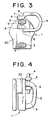
- Fig. 3 is a partially broken front view showing a process of attaching a connecting ring of the same slider.
- Fig. 4 is a side view showing the same process.
- Fig. 5 is an exploded front view of the same slider.
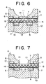
- Fig. 6 is an enlarged front view of a linking portion between the connecting ring and a pull main body in the same slider.
- Fig. 7 is an enlarged front view showing a modification of a connecting portion of the same slider.
- Fig. 8 is an enlarged front view showing another modification of the connecting portion of the same slider.
- Fig. 9 is a partially cutout front view showing a modification of the connecting ring and pull main body of the same slider.
- Fig. 10 is a perspective view of a slider having a well-known connecting ring.
- Hereinafter, embodiments of a pull of a slider for a slide fastener of the present invention will be described concretely with reference to the drawings.
- A
pull 2 of a slider for a slide fastener of the present invention is formed by combining a pull-connectingring 4, a pullmain body 10 and apin 15, and is attached to a pull-attachingportion 3 in which both ends of an attachinglever 9 are fixed to a top face of anupper blade 20 of a slider body 1. Therefore, this slider is a post-installed type in which thepull 2 is attached to the pull-attachingportion 3 after the slider main body is made, said pull-attachingportion 3 being formed integrally on the body 1 of the slider. - According to the embodiments of the slider shown in Figs. 1 to 6, the pull
main body 10 is connected to the pull-attachingportion 3 of the slider body 1 through the pull-connectingring 4. The pull-connectingring 4 has anopening 5, which opens to a side of its ring-like frame and theopening 5 is formed not smaller than the thickness or the width of an attachinglever 9 of the pull-attachingportion 3, so as to facilitate insertion of the attachinglever 9 through theopening 5. Meanwhile,thick holding portions 6 are provided on inner side edges of this opening 5 such that they are protruded in parallel to each other while steppedportions 8 are formed outside theholding portions 6 and thethick holding portions 6 havepin holes 7 through which apin 15 can be inserted. - The pull
main body 10 has a thick fitting protruded portion 11 which is provided in the center on a side where the pull main body connects to the pull-connectingring 4 such that the fitting protruded portion 11 fits to the opening 5 so as to be freely movable. Protrudent thick supportingportions 12 are provided in parallel on both sides of this fitting protruded portion 11 with gaps to which theholding portions 6 fit being freely movable. These supportingportions 12 fit to thestepped portions 8 provided on the pull-connectingring 4 so as to support theholding portions 6. Thepin holes 7 through which thepin 15 can be inserted are provided through the thick supportingportions 12 on both sides and the thick fitting protruded portion 11 in the center. In thepin hole 7 provided in and penetrating the fitting protruded portion 11, convexprotrusions 13 protruding inward from the inner peripheral face of thepin hole 7 is provided. Theseprotrusions 13 press and fix thepin 15 inserted through thepin hole 7. - The
pin 15, which is inserted through thepin holes 7 provided in and penetrating theholding portions 6 of the pull-connectingring 4 and the fitting protruded portion 11 and supportingportions 12 of the pullmain body 10 so as to join these members, preferably has spring property so that the diameter of thepin 15 can become smaller. As shown in Fig. 5, thepin 15 is provided with a wave-shaped expandingslot 16 in the length direction of a pipe or a straight expandingslot 16. - Preferably, the pull-connecting
ring 4 and the pullmain body 10 are formed by die-casting with metal such as zinc alloy. The configuration of the slider is not restricted to the pull-attaching portion in which the both ends of the attaching lever are fixed. This slider is also applicable for the pull-attaching portion whose attaching lever is a cantilever type and further, applicable for a slider with an automatic stop device having an automatic stop mechanism. - To connect the pull
main body 10 to the slider body 1, first, the pull-connectingring 4 is mounted to the pull-attachingportion 3 comprised of an attachinglever 9 formed on anupper blade 20 of the slider body 1 after the slider main body is made as shown in Figs. 3 and 4 by passing the opening 5 between theholding portions 6 through the pull-attachingportion 3 as shown in Fig. 5. Next, the fitting protruded portion 11 and the supportingportions 12 of the pullmain body 10 are inserted into theopening 5 and the steppedportions 8 of the pull-connectingring 4. Then, pin holes 7 of these members are made to coincide with each other and thepin 15 is inserted from one side of the pin holes 7. Thepin 15 is fixed with theprotrusions 13 provided in thepin hole 7 of the fitting protruded portion 11, so that the pull-connectingring 4 and the pullmain body 10 are supported by thispin 15, being freely pivotable. - To replace the pull
main body 10, thepin 15 just has to be removed from the pin holes 7 provided in the supportingportions 12 and the fitting protruded portion 11 of the pullmain body 10 and the holdingportions 6 of the pull-connectingring 4. In this way, the pull-connectingring 4 can be easily separated from the pullmain body 10, so that the pullmain body 10 or the pull-connecting ring can be replaced arbitrarily. - The protrusions for pressing and fixing the
pin 15 inserted into the pin holes 7 may be provided in the pin holes 7 of the holdingportions 6 of the pull-connectingring 4 without providing the pullmain body 10 with a fitting protruded portion 11, as shown in Fig. 7. Alternatively, the protrusions may be provided in thepin hole 7 of one of the holdingportions 6, as shown in Fig. 8. Further, as shown in Fig. 9, the pull-connectingring 4 is formed in a horseshoe shape andthick holding portions 6 are formed on both sides of the pull-connectingring 4 so as to form theopening 5. Meanwhile, the pullmain body 10 is provided with the fitting protruded portion 11 in the center of its linking portion, such that the fitting protruded portion 11 can be inserted into theopening 5, while no supportingportions 12 are provided on both sides of this fitting protruded portion 11. Theprotrusions 13 are provided in thepin hole 7 of each holdingportion 6 so as to fix thepin 15. -
- 1: slider body
- 3: pull-attaching portion
- 4: pull-connecting ring
- 5: opening
- 6: holding portion
- 7: pin hole
- 10: pull main body
- 11: fitting protruded portion
- 12: supporting portion
- 15: pin
Claims (7)
- A pull of a slider for a slide fastener comprising a pull main body (10) and a pull-connecting ring (4) having a holding portion (6) for connecting with the pull main body (10), in which pin holes (7) are formed in said pull main body (10) and said holding portion (6), and said pull main body (10) and said connecting ring (4) are linked and fixed with each other by a pin (15) to be inserted into the respective pin holes (7) so as to pivot freely each other, being characterized in that
the pull-connecting ring (4) has an opening (5) on a side thereof and holding portions (6) on both sides of the opening (5). - A pull of a slider for a slide fastener according to claim 1, being characterized in that the pull main body (10) has a fitting protruded portion (11) which can be fitted between the holding portions (6) such that said fitting protruded portion (11) is freely movable, and the fitting protruded portion (11) is provided with a pin hole (7).
- A pull of a slider for a slide fastener according to claim 2, being characterized in that supporting portions (12) are provided in parallel on both sides of the fitting protruded portion (11) with an interval, and has pin holes (7) into which the pin (15) can be inserted.
- A pull of a slider for a slide fastener according to claim 2, being characterized in that the pin (15) is fixed in the pin hole (7) provided in the fitting protruded portion (11) of the pull main body (10).
- A pull of a slider for a slide fastener according to claim 1, being characterized in that the pin (15) is fixed in the pin holes (7) provided in the holding portions (6) of the connecting ring (4).
- A pull of a slider for a slide fastener according to claim 3, being characterized in that the pin (15) is fixed in the pin holes (7) provided in the supporting portions (12) of the pull main body (10).
- A pull of a slider for a slide fastener according to claim 1, being characterized in that the connecting ring (4) consists of a die-cast product in which the opening (5) has a size not smaller than the thickness or the width of a pull-attaching portion (3) of a slider body (1).
Applications Claiming Priority (2)
| Application Number | Priority Date | Filing Date | Title |
|---|---|---|---|
| JP2001327821A JP2003125815A (en) | 2001-10-25 | 2001-10-25 | Slider tab for slide fastener |
| JP2001327821 | 2001-10-25 |
Publications (3)
| Publication Number | Publication Date |
|---|---|
| EP1306027A2 EP1306027A2 (en) | 2003-05-02 |
| EP1306027A3 EP1306027A3 (en) | 2004-05-19 |
| EP1306027B1 true EP1306027B1 (en) | 2006-06-14 |
Family
ID=19143987
Family Applications (1)
| Application Number | Title | Priority Date | Filing Date |
|---|---|---|---|
| EP02022628A Expired - Fee Related EP1306027B1 (en) | 2001-10-25 | 2002-10-09 | Pull of a slider for a slide fastener |
Country Status (9)
| Country | Link |
|---|---|
| US (1) | US20030079318A1 (en) |
| EP (1) | EP1306027B1 (en) |
| JP (1) | JP2003125815A (en) |
| KR (1) | KR100455706B1 (en) |
| CN (1) | CN1281166C (en) |
| DE (1) | DE60212290T2 (en) |
| ES (1) | ES2267918T3 (en) |
| HK (1) | HK1051788A1 (en) |
| TW (1) | TW589164B (en) |
Families Citing this family (13)
| Publication number | Priority date | Publication date | Assignee | Title |
|---|---|---|---|---|
| US7117567B1 (en) | 2003-02-12 | 2006-10-10 | Briggs & Riley Travelware Llc | Two-part connecting zipper pull |
| GB2407341B (en) * | 2003-10-24 | 2006-03-15 | Antler Ltd | A slider |
| TWI243658B (en) * | 2003-11-19 | 2005-11-21 | Ykk Corp | Slide fastener slider |
| KR100877858B1 (en) * | 2007-07-12 | 2009-01-13 | 김영석 | Pulling up ring |
| US9271548B2 (en) * | 2011-06-17 | 2016-03-01 | Ykk Corporation | Slider for slider fasteners |
| CN102771960B (en) * | 2012-07-17 | 2015-12-02 | 李甫文 | The puller slide block of interchangeable pull-tab and use the pull head of this slide block |
| KR101316641B1 (en) * | 2013-07-30 | 2013-10-15 | 박승동 | Connecting assembly for accessory |
| KR101341604B1 (en) | 2013-10-02 | 2013-12-16 | 박승동 | Manufacturing device of connecting assembly for accessory |
| US10064455B2 (en) * | 2016-04-01 | 2018-09-04 | Shah Technologies, LLC | Metal one piece slide and pull for slide fastener |
| US11432621B2 (en) | 2016-04-01 | 2022-09-06 | Shah Technologies, LLC | Metal one piece security slide and pull for slide fastener |
| US11006703B2 (en) | 2016-04-01 | 2021-05-18 | Shah Technologies, LLC | Metal one piece slide and pull for slide fastener |
| KR101878726B1 (en) * | 2017-05-24 | 2018-07-16 | 김기선 | Zipper |
| CN113142753B (en) * | 2020-01-22 | 2023-01-17 | Ykk株式会社 | Slider and slider assembling method |
Family Cites Families (5)
| Publication number | Priority date | Publication date | Assignee | Title |
|---|---|---|---|---|
| US3964252A (en) * | 1975-09-04 | 1976-06-22 | Timex Corporation | Adjustable hinge band |
| JPS6317609U (en) * | 1986-07-18 | 1988-02-05 | ||
| JPH085610Y2 (en) * | 1988-11-15 | 1996-02-21 | ワイケイケイ株式会社 | Slider puller for slide fastener |
| TW330378U (en) * | 1997-09-26 | 1998-04-21 | Keen Ching Ind Co Ltd | Pull tab of the zipper slide |
| US6035497A (en) * | 1998-07-14 | 2000-03-14 | Jackson; Terry R. | Zipper pull tab |
-
2001
- 2001-10-25 JP JP2001327821A patent/JP2003125815A/en active Pending
-
2002
- 2002-09-16 TW TW091121161A patent/TW589164B/en not_active IP Right Cessation
- 2002-09-23 US US10/253,043 patent/US20030079318A1/en not_active Abandoned
- 2002-10-09 EP EP02022628A patent/EP1306027B1/en not_active Expired - Fee Related
- 2002-10-09 ES ES02022628T patent/ES2267918T3/en not_active Expired - Lifetime
- 2002-10-09 DE DE60212290T patent/DE60212290T2/en not_active Expired - Lifetime
- 2002-10-11 KR KR10-2002-0062061A patent/KR100455706B1/en not_active IP Right Cessation
- 2002-10-24 CN CNB021471584A patent/CN1281166C/en not_active Expired - Lifetime
-
2003
- 2003-06-09 HK HK03104023A patent/HK1051788A1/en not_active IP Right Cessation
Also Published As
| Publication number | Publication date |
|---|---|
| US20030079318A1 (en) | 2003-05-01 |
| KR20030035893A (en) | 2003-05-09 |
| TW589164B (en) | 2004-06-01 |
| CN1413538A (en) | 2003-04-30 |
| EP1306027A3 (en) | 2004-05-19 |
| EP1306027A2 (en) | 2003-05-02 |
| CN1281166C (en) | 2006-10-25 |
| KR100455706B1 (en) | 2004-11-06 |
| HK1051788A1 (en) | 2003-08-22 |
| DE60212290T2 (en) | 2007-05-24 |
| JP2003125815A (en) | 2003-05-07 |
| DE60212290D1 (en) | 2006-07-27 |
| ES2267918T3 (en) | 2007-03-16 |
Similar Documents
| Publication | Publication Date | Title |
|---|---|---|
| EP1306027B1 (en) | Pull of a slider for a slide fastener | |
| JP3733311B2 (en) | Slide handle for slide fastener | |
| US4829638A (en) | Automatically locking slider | |
| TWI243657B (en) | Slider for slide fastener | |
| US5033171A (en) | Buckle for connecting two straps or the like | |
| JP2544865Y2 (en) | Watch band clasp | |
| EP2005852B1 (en) | Double-sided engaging element for slide fastener | |
| JP3829158B2 (en) | Joint for jewelry | |
| US6634066B2 (en) | Upper stopper device for slide fastener | |
| JP2008517685A (en) | Bracelet clasp with sliding latch | |
| JP3987954B2 (en) | Clasp with folding arm | |
| CA2176657C (en) | Automatic lock slider for slide fastener | |
| US20020178553A1 (en) | Zipper slide for invisible zipper | |
| JP4331600B2 (en) | Bracelet with clasp | |
| US6591464B2 (en) | Zipper slide of zip fastener | |
| EP0402690B1 (en) | Slide fastener slider | |
| KR101286365B1 (en) | Method of manufacturing a earing having all parts made of precious metal | |
| CN108354278B (en) | Zipper head | |
| JP2000102404A (en) | Buckle structure | |
| JPH049841Y2 (en) | ||
| JP2551067Y2 (en) | Metal clasp for portable band | |
| JP2681870B2 (en) | Nakadome metal fittings for watch bands | |
| EP1020132B1 (en) | Method of removing a pull tab from a slide fastener | |
| JP3220902B2 (en) | Accessories for accessories | |
| JP3490284B2 (en) | Central clasp of band and wrist watch using the clasp |
Legal Events
| Date | Code | Title | Description |
|---|---|---|---|
| PUAI | Public reference made under article 153(3) epc to a published international application that has entered the european phase |
Free format text: ORIGINAL CODE: 0009012 |
|
| AK | Designated contracting states |
Designated state(s): AT BE BG CH CY CZ DE DK EE ES FI FR GB GR IE IT LI LU MC NL PT SE SK TR |
|
| AX | Request for extension of the european patent |
Extension state: AL LT LV MK RO SI |
|
| PUAL | Search report despatched |
Free format text: ORIGINAL CODE: 0009013 |
|
| AK | Designated contracting states |
Kind code of ref document: A3 Designated state(s): AT BE BG CH CY CZ DE DK EE ES FI FR GB GR IE IT LI LU MC NL PT SE SK TR |
|
| AX | Request for extension of the european patent |
Extension state: AL LT LV MK RO SI |
|
| 17P | Request for examination filed |
Effective date: 20040811 |
|
| AKX | Designation fees paid |
Designated state(s): DE ES FR GB IT |
|
| GRAP | Despatch of communication of intention to grant a patent |
Free format text: ORIGINAL CODE: EPIDOSNIGR1 |
|
| GRAS | Grant fee paid |
Free format text: ORIGINAL CODE: EPIDOSNIGR3 |
|
| GRAA | (expected) grant |
Free format text: ORIGINAL CODE: 0009210 |
|
| AK | Designated contracting states |
Kind code of ref document: B1 Designated state(s): DE ES FR GB IT |
|
| PG25 | Lapsed in a contracting state [announced via postgrant information from national office to epo] |
Ref country code: IT Free format text: LAPSE BECAUSE OF FAILURE TO SUBMIT A TRANSLATION OF THE DESCRIPTION OR TO PAY THE FEE WITHIN THE PRESCRIBED TIME-LIMIT;WARNING: LAPSES OF ITALIAN PATENTS WITH EFFECTIVE DATE BEFORE 2007 MAY HAVE OCCURRED AT ANY TIME BEFORE 2007. THE CORRECT EFFECTIVE DATE MAY BE DIFFERENT FROM THE ONE RECORDED. Effective date: 20060614 |
|
| REG | Reference to a national code |
Ref country code: GB Ref legal event code: FG4D |
|
| REF | Corresponds to: |
Ref document number: 60212290 Country of ref document: DE Date of ref document: 20060727 Kind code of ref document: P |
|
| ET | Fr: translation filed | ||
| REG | Reference to a national code |
Ref country code: ES Ref legal event code: FG2A Ref document number: 2267918 Country of ref document: ES Kind code of ref document: T3 |
|
| PLBE | No opposition filed within time limit |
Free format text: ORIGINAL CODE: 0009261 |
|
| STAA | Information on the status of an ep patent application or granted ep patent |
Free format text: STATUS: NO OPPOSITION FILED WITHIN TIME LIMIT |
|
| 26N | No opposition filed |
Effective date: 20070315 |
|
| PGFP | Annual fee paid to national office [announced via postgrant information from national office to epo] |
Ref country code: DE Payment date: 20091001 Year of fee payment: 8 Ref country code: ES Payment date: 20091023 Year of fee payment: 8 |
|
| PGFP | Annual fee paid to national office [announced via postgrant information from national office to epo] |
Ref country code: FR Payment date: 20091029 Year of fee payment: 8 Ref country code: GB Payment date: 20091007 Year of fee payment: 8 Ref country code: IT Payment date: 20091016 Year of fee payment: 8 |
|
| GBPC | Gb: european patent ceased through non-payment of renewal fee |
Effective date: 20101009 |
|
| PG25 | Lapsed in a contracting state [announced via postgrant information from national office to epo] |
Ref country code: FR Free format text: LAPSE BECAUSE OF NON-PAYMENT OF DUE FEES Effective date: 20101102 |
|
| REG | Reference to a national code |
Ref country code: FR Ref legal event code: ST Effective date: 20110630 |
|
| PG25 | Lapsed in a contracting state [announced via postgrant information from national office to epo] |
Ref country code: GB Free format text: LAPSE BECAUSE OF NON-PAYMENT OF DUE FEES Effective date: 20101009 |
|
| REG | Reference to a national code |
Ref country code: DE Ref legal event code: R119 Ref document number: 60212290 Country of ref document: DE Effective date: 20110502 |
|
| REG | Reference to a national code |
Ref country code: ES Ref legal event code: FD2A Effective date: 20111118 |
|
| PG25 | Lapsed in a contracting state [announced via postgrant information from national office to epo] |
Ref country code: IT Free format text: LAPSE BECAUSE OF NON-PAYMENT OF DUE FEES Effective date: 20101009 |
|
| PG25 | Lapsed in a contracting state [announced via postgrant information from national office to epo] |
Ref country code: ES Free format text: LAPSE BECAUSE OF NON-PAYMENT OF DUE FEES Effective date: 20101010 |
|
| PG25 | Lapsed in a contracting state [announced via postgrant information from national office to epo] |
Ref country code: DE Free format text: LAPSE BECAUSE OF NON-PAYMENT OF DUE FEES Effective date: 20110502 |