EP1305224B1 - Stand-up bag of a heat-sealable plastic film for flowable products - Google Patents
Stand-up bag of a heat-sealable plastic film for flowable products Download PDFInfo
- Publication number
- EP1305224B1 EP1305224B1 EP01936035A EP01936035A EP1305224B1 EP 1305224 B1 EP1305224 B1 EP 1305224B1 EP 01936035 A EP01936035 A EP 01936035A EP 01936035 A EP01936035 A EP 01936035A EP 1305224 B1 EP1305224 B1 EP 1305224B1
- Authority
- EP
- European Patent Office
- Prior art keywords
- spout
- bag
- discharge
- side seams
- wall
- Prior art date
- Legal status (The legal status is an assumption and is not a legal conclusion. Google has not performed a legal analysis and makes no representation as to the accuracy of the status listed.)
- Expired - Lifetime
Links
- 239000002985 plastic film Substances 0.000 title claims abstract description 4
- 229920006255 plastic film Polymers 0.000 title claims abstract description 4
- 230000009969 flowable effect Effects 0.000 title claims description 3
- 239000007788 liquid Substances 0.000 claims description 9
- 239000012263 liquid product Substances 0.000 claims description 5
- XLYOFNOQVPJJNP-UHFFFAOYSA-N water Substances O XLYOFNOQVPJJNP-UHFFFAOYSA-N 0.000 claims description 4
- 239000000047 product Substances 0.000 claims description 2
- 239000010410 layer Substances 0.000 description 9
- 230000035622 drinking Effects 0.000 description 6
- 238000007789 sealing Methods 0.000 description 6
- 239000005026 oriented polypropylene Substances 0.000 description 4
- 238000004519 manufacturing process Methods 0.000 description 3
- 239000004743 Polypropylene Substances 0.000 description 2
- 230000004888 barrier function Effects 0.000 description 2
- WXZMFSXDPGVJKK-UHFFFAOYSA-N pentaerythritol Chemical compound OCC(CO)(CO)CO WXZMFSXDPGVJKK-UHFFFAOYSA-N 0.000 description 2
- 239000005020 polyethylene terephthalate Substances 0.000 description 2
- 229920000139 polyethylene terephthalate Polymers 0.000 description 2
- 241000219198 Brassica Species 0.000 description 1
- 235000003351 Brassica cretica Nutrition 0.000 description 1
- 235000003343 Brassica rupestris Nutrition 0.000 description 1
- 239000004952 Polyamide Substances 0.000 description 1
- XAGFODPZIPBFFR-UHFFFAOYSA-N aluminium Chemical compound [Al] XAGFODPZIPBFFR-UHFFFAOYSA-N 0.000 description 1
- 229910052782 aluminium Inorganic materials 0.000 description 1
- 239000004411 aluminium Substances 0.000 description 1
- QKSKPIVNLNLAAV-UHFFFAOYSA-N bis(2-chloroethyl) sulfide Chemical compound ClCCSCCCl QKSKPIVNLNLAAV-UHFFFAOYSA-N 0.000 description 1
- 229920001577 copolymer Polymers 0.000 description 1
- 235000013365 dairy product Nutrition 0.000 description 1
- 230000003247 decreasing effect Effects 0.000 description 1
- 235000008960 ketchup Nutrition 0.000 description 1
- 239000008268 mayonnaise Substances 0.000 description 1
- 235000010746 mayonnaise Nutrition 0.000 description 1
- 238000001465 metallisation Methods 0.000 description 1
- 235000010460 mustard Nutrition 0.000 description 1
- 229920002647 polyamide Polymers 0.000 description 1
- 229920000728 polyester Polymers 0.000 description 1
- 229920000098 polyolefin Polymers 0.000 description 1
- 239000002344 surface layer Substances 0.000 description 1
Images


Classifications
-
- B—PERFORMING OPERATIONS; TRANSPORTING
- B65—CONVEYING; PACKING; STORING; HANDLING THIN OR FILAMENTARY MATERIAL
- B65D—CONTAINERS FOR STORAGE OR TRANSPORT OF ARTICLES OR MATERIALS, e.g. BAGS, BARRELS, BOTTLES, BOXES, CANS, CARTONS, CRATES, DRUMS, JARS, TANKS, HOPPERS, FORWARDING CONTAINERS; ACCESSORIES, CLOSURES, OR FITTINGS THEREFOR; PACKAGING ELEMENTS; PACKAGES
- B65D75/00—Packages comprising articles or materials partially or wholly enclosed in strips, sheets, blanks, tubes or webs of flexible sheet material, e.g. in folded wrappers
- B65D75/008—Standing pouches, i.e. "Standbeutel"
-
- B—PERFORMING OPERATIONS; TRANSPORTING
- B65—CONVEYING; PACKING; STORING; HANDLING THIN OR FILAMENTARY MATERIAL
- B65D—CONTAINERS FOR STORAGE OR TRANSPORT OF ARTICLES OR MATERIALS, e.g. BAGS, BARRELS, BOTTLES, BOXES, CANS, CARTONS, CRATES, DRUMS, JARS, TANKS, HOPPERS, FORWARDING CONTAINERS; ACCESSORIES, CLOSURES, OR FITTINGS THEREFOR; PACKAGING ELEMENTS; PACKAGES
- B65D75/00—Packages comprising articles or materials partially or wholly enclosed in strips, sheets, blanks, tubes or webs of flexible sheet material, e.g. in folded wrappers
- B65D75/52—Details
- B65D75/58—Opening or contents-removing devices added or incorporated during package manufacture
- B65D75/5861—Spouts
- B65D75/5866—Integral spouts
Definitions
- the invention relates to a stand-up bag of a heat-sealable plastic film for flowable products, said bag comprising:
- EP-Al-0052151 discloses a bag of the above type provided with a comparatively wide spout through which the bag is filled. After filling of the bag, the spout opening is sealed, whereby the bag is closed.
- the object of the invention is to provide a stand-up bag of the above type provided with a discharge spout suitable for drinking out of the bag.
- the stand-up bag according to the invention is characterised in that one of the side seams has an unsealed portion between the V-fold of the bottom wall and the V-fold of the top wall so as to provide an opening, into which a filling pipe can be inserted for filling the bag, and in that after removal of the removable end portion the discharge spout has an outer width of less than or equal to 50 mm at least in the spout discharge portion provided by removing the removable end portion.
- the bag is completely ready-made with the exception of me said unsealed portion of one side seam, when the bag is filled with the liquid product to be packed therein.
- the discharge spout with the discharge passage and the removable end portion have been formed before the liquid product is filled into the bag.
- the outer discharge portion of the discharge spout may be inserted into a person's mouth or between a person's lips, whereby the discharge spout serves as a drinking spout. Furthermore the narrow width of the spout and thus of the discharge passage allows a user to easily control the discharge of the contents of the bag, eg if the contents or a portion thereof has to be transferred to another container and the bag is turned and pressure is applied thereto.
- the outer width of the discharge spout may be less than or equal to 40 mm, preferably less than or equal to 30 mm, and most preferably less than or equal to 25 mm, at least in the spout discharge portion provided by removing the removable end portion. Decreasing discharge spout sizes make drinking out of the spout more pleasant for an increasing number of persons, including children.
- the interior distance between the spout side seams may be less than or equal to 30 mm, preferably less than or equal to 20 mm and most preferably less than or equal to 15 mm, at least in the area defining the effective flow area of the discharge passage.
- the effective flow area of the passage is chosen in consideration of the desired flow velocity and the viscosity of the liquid product contained in the bag.
- the width of the discharge passage may be such that the parts of the second top wall panel and the second side wall, respectively, forming the spout abut each other for closing the passage so as to prevent a liquid contained in the container and having a viscosity corresponding to the viscosity of water substantially from flowing out through the spout when the bag rests on the second side wall subsequent to the removal of the removable end portion.
- the discharge passage has such a width that in order to make the liquid contained in the container flow out through the discharge passage, a certain amount of pressure has to be applied to the liquid product in the bag by squeezing the bag. The risk of unintended discharge of the liquid contained in the bag is thus minimized.
- the spout side seams may extend substantially parallel to each other so as to provide a discharge passage having the same flow area over its entire length.
- the spout side seams may, however, also extend in a substantially converging manner when seen in outward direction, whereby the effective flow area of the discharge passage is positioned at the discharge end of the spout.
- This embodiment of the invention is considered particularly advantageous in connection with more viscous or paste-like liquids such as sour dairy product, mayonnaise, ketchup and mustard, where a controlled discharge is desired.
- the spout side seams may, however, also extend in a substantially diverging manner when seen in outward direction, whereby the smallest and effective flow area determines the volume flow rate through the passage, when the bag is squeezed. Conversely the outer end of the passage having a larger flow area determines the discharge velocity.
- the embodiment is thus considered particularly advantageous in cases, where the user is to drink directly out of the spout, the desired combination of volume flow rate and discharge velocity thereby being obtained, when the bag is squeezed.
- the bag may have an interior volume less than or equal to one litre, but may also have an interior volume less than or equal to 0.5 litres or less than or equal to 0.25 litres.
- a weakened portion in form of an incision and/or a laser perforation may be provided between the removable and portion and the discharge spout to obtain a defined removal of the removable end portion.
- one or more flexible films are used and which - when seen in relation to the interior of the bag - has/have at least one inner heat-sealable surface, preferably comprising a polyolefin, ie PE or PP.
- a softer or more flexible, eg thicker, film is used for the top and bottom walls than for the side walls to obtain the intended standing properties.
- multi-layer films are preferably used comprising an inner heat-sealable surface layer.
- the laminate COEX OPP/PETP may for instance be used, in which the PE layer is on inner side seen in relation to the finished or prefabricated bag and COEX OPP denotes a co-extruded oriented polypropylene film on either side provided with a thin sealing medium layer comprising a copolymer of PP and PE.
- a barrier layer eg a metallisation layer or an aluminium film, maybe provided between the PBTP layer and the PE layer or between the COBX OPP film and the PBTP layer.
- the PETP layer may be replaced by an oriented polyamide, OPA.
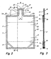
- the stand-up bag shown in Figs. 1 to 3 comprises a first side wall 1 and a second side wall 2 arranged opposite each other and a top wall 3 and a bottom wall 4 also arranged opposite each other.
- the side walls 1,2 are sealed together by means of side sealing seams 5,6 extending along two opposed side edges.
- the bottom wall 4 is folded inwards along a bottom wall fold 13 and sealed to the side walls 1,2 along two opposed transverse bottom seams 7, 8.
- the bottom wall panels 4a, 4b are sealed together and also sealed to the side walls 1,2 along the bottom side seams 9,10 aligned with the side seams 5,6.
- the top wall is folded inwards into V-shape along a top wall fold 14 and thus comprises a first top wall panel 3a and a second top wall panel 3b.
- the two top wall panels 3a, 3b are sealed together and sealed to the first side wall and the second side wall, respectively, along top side seams 15,16 aligned with the side seams 5,6.
- the first top wall panel 3a is sealed to the first side wall 1 along a transverse top sealing 11.
- the second top wall panel 3b and the second side wall 2 are sealed together along transverse aligned top seam potions 12a, 12b, an unsealed central area being provided therebetween.
- the second top wall panel 3b and the second side wall 2 both extend beyond the upper transverse top seam portions 12a, 12b, which are flush with the upper transverse top seam 11.
- the extension 17 of the second top wall panel 3b and the extension 18 of the second side wall 2 are sealed together to form a discharge spout 19 having a discharge passage 20.
- the discharge passage 20 is sideways defined by the spout side seams 21,22 connected to the respective upper transverse top seam portion. 12a and 12b.
- the discharge passage 20 is closed by means of a sealing seam 23 interconnecting the spout side seams 21, 22 in an outer removable end portion 24 providing the passage with a discharge opening 25 when removed.
- the discharge spout 19 is provided with an incision 26 for easy and wen-defined removal of the removable end portion 24.
- the spout In order for the discharge spout 19 to serve as a drinking spout after the removable discharge portion 24 has been removed, the spout has an outer width B in the discharge portion 27 under the incision 26 preferably of less than 30 mm and a projecting length L preferably exceeding 10 mm.
- the shape and size of the removable end portion 24 may be altered in any way, as it has no influence on the function of the discharge spout 19 as a drinking spout.
- the spout side seams 21, 22 extend substantially parallel such that the discharge passage 20 has a substantially constant effective flow area.
- the chosen effective flow area preferably corresponds to an effective passage width b preferably less than or equal to 15 mm, most preferably less than or equal to 10 mm, a suitable combination of the volume flow rate through The passage and the discharge velocity from the passage being obtained thereby.
- a self-sealing passage is obtained in the sense that the wall portions of the passage abut each other substantially so as to prevent liquid having a viscosity corresponding to that of water from flowing out of the passage, when pressure is not applied to the liquid contained in the bag by squeezing the latter when it horizontally positioned.
- Figs. 1 and 2 further illustrate a prefabricated bag according to the invention for the manufacture of the bag.
- the prefabricated bag is identical to the shown bag with the exception that the side seam 6 has a unsealed area 30 between the bottom wall fold 13 of the bottom wall 4 and the top wall fold 14 of the top wall 3, said area 30 being between the lines 31 and 32.
- the unsealed area is further illustrated by means of dotted lines between the lines 31 and 32.
- the unsealed area 30 of the side seam 6 between the side walls 1 and 2 forms an opening 33 into the interior of the bag.
- a filling tube for filling the prefabricated bag may be inserted through the opening 33. Subsequent to filling of the prefabricated bag the filling opening 33 is closed by sealing the side walls 2 together in the unsealed area 30 of the side seam 6.
- the bag may further be provided with oblique bottom side seams 34,35,36,37 extending from a level of the side seams 5,6 corresponding to the bottom wall fold 13 and between a side seam 5,6 and a transverse bottom seam 7,8.
- Each of the oblique seams 34-37 connects a bottom wall panel 4a,4b to the adjacent side wall 1,2.
- the provision of the oblique bottom side seams 34-37 makes it possible to cut away the corner portions of the side walls 1,2 and corner portions of the bottom wall 4, said corner portions of the side walls being positioned outside of these oblique seams.
- the top wall 3 may be connected to the side walls 1,2 by means of corresponding oblique top side seams.
- a bag is diagrammatically shown comprising a discharge spout 39 having spout side seams 41,42 extending from the top seams portions 32a,32b so as to define a discharge passage 40 converging when seen in outward direction.
- the effective sectional area offlow of the discharge passage is thus determined by the inner width b of the passage 40 at the discharge opening 45 provided when the removable end portion 44 has been torn off along the tear line defined by the tear incision 46.
- the width and the projecting length of the discharge spout 39 correspond to the width and length of the above discharge spout 19.
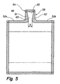
- Fig. 5 is a diagrammatic view of a bag according to the invention, said bag comprising a discharge spout 59 with spout side seams 61,62 extending such from the upper top seam portions 52a,52b so as to define a discharge passage 60 substantially diverging when seen in outward direction.
- the smallest width b or the effective flow area of the discharge passage 60 is thus spaced apart from the discharge opening 65 formed by tearing off the removable end portion 64 along the tear line defined by the tear incision 66.
- the width b of the discharge passage 60 may for instance be between 6-10 mm and the width of the passage in the discharge opening 65 may for instance be 15 mm.
- the outer width and the projecting length of the discharge spout 59 is advantageously as described above with reference to the discharge spout 19.
Landscapes
- Engineering & Computer Science (AREA)
- Mechanical Engineering (AREA)
- Bag Frames (AREA)
- Wrappers (AREA)
- Packages (AREA)
- Making Paper Articles (AREA)
Abstract
Description
- The invention relates to a stand-up bag of a heat-sealable plastic film for flowable products, said bag comprising:
- a first and a second opposing side wall interconnected along two side seams,
- a bottom wall folded inwards into V-shape and having with two bottom wall panels connected to the first and the second side wall, respectively, along transverse bottom connections and along bottom side seams,
- a top wall folded inwards into V-shape and having with a first top wall panel connected to the first side wall and a second top wall panel connected to the second side wall along top side seams, the first top wall panel further being connected to the first side wall along a transverse top connection, and the second top wall panel and the second side wall further extending beyond the transverse upper connection and sealed to each other to form a discharge spout having a discharge passage closed by a removable end portion and sideways defined by spout side seams.
- DB published specification No. A1 39 25 981 and EP patent No 0 052 151 both disclose a stand-up bag of the above type provided with a comparatively large or wide discharge spout.
- Further EP-Al-0052151 discloses a bag of the above type provided with a comparatively wide spout through which the bag is filled. After filling of the bag, the spout opening is sealed, whereby the bag is closed.
- The object of the invention is to provide a stand-up bag of the above type provided with a discharge spout suitable for drinking out of the bag.
- The stand-up bag according to the invention is characterised in that one of the side seams has an unsealed portion between the V-fold of the bottom wall and the V-fold of the top wall so as to provide an opening, into which a filling pipe can be inserted for filling the bag, and in that after removal of the removable end portion the discharge spout has an outer width of less than or equal to 50 mm at least in the spout discharge portion provided by removing the removable end portion. As a result the bag is completely ready-made with the exception of me said unsealed portion of one side seam, when the bag is filled with the liquid product to be packed therein. Especially, the discharge spout with the discharge passage and the removable end portion have been formed before the liquid product is filled into the bag. After filling of the bag only the side walls in the unsealed portion of said one side seams need be sealed. Further after removal of the removable end portion the outer discharge portion of the discharge spout may be inserted into a person's mouth or between a person's lips, whereby the discharge spout serves as a drinking spout. Furthermore the narrow width of the spout and thus of the discharge passage allows a user to easily control the discharge of the contents of the bag, eg if the contents or a portion thereof has to be transferred to another container and the bag is turned and pressure is applied thereto.
- As every person has an individual mouth size and some people find it uncomfortable to insert large objects into their mouths, according to the invention the outer width of the discharge spout may be less than or equal to 40 mm, preferably less than or equal to 30 mm, and most preferably less than or equal to 25 mm, at least in the spout discharge portion provided by removing the removable end portion. Decreasing discharge spout sizes make drinking out of the spout more pleasant for an increasing number of persons, including children.
- Moreover according to the invention the interior distance between the spout side seams may be less than or equal to 30 mm, preferably less than or equal to 20 mm and most preferably less than or equal to 15 mm, at least in the area defining the effective flow area of the discharge passage.
- Naturally, the effective flow area of the passage is chosen in consideration of the desired flow velocity and the viscosity of the liquid product contained in the bag. In connection with the liquids having a viscosity corresponding to that of water, it may for instance be advantageous to use an effective passage width of 6 to 10 mm to obtain a flow velocity and a volume flow rate perceived as pleasant by the individual drinking out of the bag.
- Furthermore according to the invention the width of the discharge passage may be such that the parts of the second top wall panel and the second side wall, respectively, forming the spout abut each other for closing the passage so as to prevent a liquid contained in the container and having a viscosity corresponding to the viscosity of water substantially from flowing out through the spout when the bag rests on the second side wall subsequent to the removal of the removable end portion. As a result user convenience is obtained in that the contents of the bag do not flow out, if the bag falls over or a user inadvertently places the bag on the second side wall after opening of the bag.
- Moreover according to the invention the discharge passage has such a width that in order to make the liquid contained in the container flow out through the discharge passage, a certain amount of pressure has to be applied to the liquid product in the bag by squeezing the bag. The risk of unintended discharge of the liquid contained in the bag is thus minimized.
- Moreover according to the invention the spout side seams may extend substantially parallel to each other so as to provide a discharge passage having the same flow area over its entire length.
- According to yet another embodiment of the invention the spout side seams may, however, also extend in a substantially converging manner when seen in outward direction, whereby the effective flow area of the discharge passage is positioned at the discharge end of the spout. This embodiment of the invention is considered particularly advantageous in connection with more viscous or paste-like liquids such as sour dairy product, mayonnaise, ketchup and mustard, where a controlled discharge is desired.
- According to a further embodiment of the invention the spout side seams may, however, also extend in a substantially diverging manner when seen in outward direction, whereby the smallest and effective flow area determines the volume flow rate through the passage, when the bag is squeezed. Conversely the outer end of the passage having a larger flow area determines the discharge velocity. The embodiment is thus considered particularly advantageous in cases, where the user is to drink directly out of the spout, the desired combination of volume flow rate and discharge velocity thereby being obtained, when the bag is squeezed.
- Moreover according to the invention the bag may have an interior volume less than or equal to one litre, but may also have an interior volume less than or equal to 0.5 litres or less than or equal to 0.25 litres.
- Furthermore according to the invention a weakened portion in form of an incision and/or a laser perforation may be provided between the removable and portion and the discharge spout to obtain a defined removal of the removable end portion.
- For the manufacture of the bag and/or the prefabricated bag according to the invention one or more flexible films are used and which - when seen in relation to the interior of the bag - has/have at least one inner heat-sealable surface, preferably comprising a polyolefin, ie PE or PP. Preferably, a softer or more flexible, eg thicker, film is used for the top and bottom walls than for the side walls to obtain the intended standing properties. Furthermore multi-layer films are preferably used comprising an inner heat-sealable surface layer. For the manufacture of the bag the laminate COEX OPP/PETP (polyester) may for instance be used, in which the PE layer is on inner side seen in relation to the finished or prefabricated bag and COEX OPP denotes a co-extruded oriented polypropylene film on either side provided with a thin sealing medium layer comprising a copolymer of PP and PE. In order to obtain enhanced barrier properties a barrier layer, eg a metallisation layer or an aluminium film, maybe provided between the PBTP layer and the PE layer or between the COBX OPP film and the PBTP layer. Furthermore the PETP layer may be replaced by an oriented polyamide, OPA.
- The invention is explained in greater detail below with reference to the accompanying drawings, in which
- fig. 1 is an isometric view of a stand-up bag according to the invention,
- Fig. 2 illustrates a collapsed stand-up bag according to the invention seen in a side view in the direction II in Fig. 1,
- Fig. 3 is a sectional view along the line III-III in Fig. 2,
- Fig. 4 is a side view corresponding to that in Fig. 2 of a bag according to the invention comprising a first alternative embodiment of the discharge spout, and
- Fig. 5 is a side view corresponding to that in Fig. 2 of a bag according to the invention comprising a second alternative embodiment of the discharge spout.
- The stand-up bag shown in Figs. 1 to 3 comprises a
first side wall 1 and asecond side wall 2 arranged opposite each other and atop wall 3 and abottom wall 4 also arranged opposite each other. Theside walls side sealing seams bottom wall 4 is folded inwards along abottom wall fold 13 and sealed to theside walls bottom wall panels 4a, 4b are sealed together and also sealed to theside walls bottom side seams side seams - In a corresponding manner the top wall is folded inwards into V-shape along a
top wall fold 14 and thus comprises a first top wall panel 3a and a secondtop wall panel 3b. The twotop wall panels 3a, 3b are sealed together and sealed to the first side wall and the second side wall, respectively, alongtop side seams side seams first side wall 1 along a transverse top sealing 11. The secondtop wall panel 3b and thesecond side wall 2 are sealed together along transverse alignedtop seam potions top wall panel 3b and thesecond side wall 2 both extend beyond the upper transversetop seam portions top seam 11. Theextension 17 of the secondtop wall panel 3b and theextension 18 of thesecond side wall 2 are sealed together to form adischarge spout 19 having adischarge passage 20. Thedischarge passage 20 is sideways defined by thespout side seams discharge passage 20 is closed by means of a sealingseam 23 interconnecting thespout side seams removable end portion 24 providing the passage with a discharge opening 25 when removed. In the embodiment shown in figs. 1-3, thedischarge spout 19 is provided with anincision 26 for easy and wen-defined removal of theremovable end portion 24. - In order for the
discharge spout 19 to serve as a drinking spout after theremovable discharge portion 24 has been removed, the spout has an outer width B in thedischarge portion 27 under theincision 26 preferably of less than 30 mm and a projecting length L preferably exceeding 10 mm. The shape and size of theremovable end portion 24 may be altered in any way, as it has no influence on the function of thedischarge spout 19 as a drinking spout. - In the embodiment shown in Figs. 1-3 the
spout side seams discharge passage 20 has a substantially constant effective flow area. The chosen effective flow area preferably corresponds to an effective passage width b preferably less than or equal to 15 mm, most preferably less than or equal to 10 mm, a suitable combination of the volume flow rate through The passage and the discharge velocity from the passage being obtained thereby. At a suitably small effective passage width, a self-sealing passage is obtained in the sense that the wall portions of the passage abut each other substantially so as to prevent liquid having a viscosity corresponding to that of water from flowing out of the passage, when pressure is not applied to the liquid contained in the bag by squeezing the latter when it horizontally positioned. - Figs. 1 and 2 further illustrate a prefabricated bag according to the invention for the manufacture of the bag. The prefabricated bag is identical to the shown bag with the exception that the
side seam 6 has a unsealedarea 30 between the bottom wall fold 13 of thebottom wall 4 and thetop wall fold 14 of thetop wall 3, saidarea 30 being between thelines lines area 30 of theside seam 6 between theside walls side walls 2 together in the unsealedarea 30 of theside seam 6. - As shown in Figs. 1 and 2, the bag may further be provided with oblique bottom side seams 34,35,36,37 extending from a level of the side seams 5,6 corresponding to the
bottom wall fold 13 and between aside seam bottom wall panel 4a,4b to theadjacent side wall side walls bottom wall 4, said corner portions of the side walls being positioned outside of these oblique seams. Naturally, thetop wall 3 may be connected to theside walls - Referring now to Fig. 4, in which a bag is diagrammatically shown comprising a
discharge spout 39 having spout side seams 41,42 extending from thetop seams portions discharge passage 40 converging when seen in outward direction. The effective sectional area offlow of the discharge passage is thus determined by the inner width b of thepassage 40 at thedischarge opening 45 provided when theremovable end portion 44 has been torn off along the tear line defined by thetear incision 46. - Advantageously, the width and the projecting length of the
discharge spout 39 correspond to the width and length of theabove discharge spout 19. - Fig. 5 is a diagrammatic view of a bag according to the invention, said bag comprising a
discharge spout 59 with spout side seams 61,62 extending such from the uppertop seam portions discharge opening 65 formed by tearing off theremovable end portion 64 along the tear line defined by thetear incision 66. The width b of the discharge passage 60 may for instance be between 6-10 mm and the width of the passage in thedischarge opening 65 may for instance be 15 mm. - The outer width and the projecting length of the
discharge spout 59 is advantageously as described above with reference to thedischarge spout 19.
Claims (9)
- A stand-up bag of a heat-sealable plastic film for flowable products, said bag comprising:a first and a second opposing side wall (1,2) being interconnected along two side seams (5,6),a bottom wall (4) folded in wards into V-shape and having with two bottom wall panels (4a,4b) connected, to the first and the second side wall, respectively, along transverse bottom connections (7,8) and along bottom side seams (34-36),a top wall (3) folded inwards into V-shape and having with a first top wall panel (3a) connected to the first side wall (1) and a second top wall panel (3b) connected to the second side wall (2) along top side seams (15,16), the fast top wall panel (3a) farther connected to the first side wall (1) along a transverse top connection (11) and the second top wall panel (3b) and the second side wall (2) further extending beyond the transverse top connection (11) and sealed together to form a discharge spout (19;39;59) having a discharge passage (20;40;60) closed by the means of a removable end portion (24, 44, 64) and sideways defined by spout side seams (21, 22; 41, 42; 61, 62),characterised in that one of the side seams (6) has an unsealed area (30) between the V-fold (13) of the bottom wall (4) and the V-fold (14) of the top wall (3) so as to provide an opening (33) in which a filling tube can be inserted for filling the prefabricated bag, and in that after removal of the removable end portion (24;44;64) the discharge spout (19;39;59) has an outer width (B) of less than or equal to 50 mm at least in the spout discharge portion (27) provided by removing the removable end portion.
- A bag according to claim 1, characterised in that the outer width (9) of the discharge spout (19; 39; 59) is leas than 40 mm, preferably less than 30 mm and most preferably less than 25 mm, at least in the spout discharge portion provided by removing the removable portion.
- A bag according to claim 1 or 2, characterised in that the interior distance (b) between the spout side seams (21, 22; 41, 42; 61, 62) is less than or equal to 30 mm, preferably less than or equal to 20 mm and most preferably less than or equal to 15 mm, at least in area defining the effective flow area of the discharge passage (19; 39; 59).
- A bag according to claim 3, characterised in that the width of the discharge passage (20;40;60) is such that the parts of the second top wall panel (3b) and the second side wall (2), respectively, forming the spout abut each other for closing the passage so as to prevent a liquid contained in the container and having a viscosity corresponding to the viscosity of water substantially from flowing out through the spout when the bag rests on the second side wall (2) after the removal of the removable end portion.
- A bag according to claim 4, characterised in that the discharge passage (20;40;60) has such a width that in order to make the liquid contained in the container flow out through the discharge passage, a certain amount of pressure has to be applied on the liquid product in the bag by squeezing the bag.
- A bag according to any of the preceding claims, characterised in that the spout side seams (21, 22) extend substantially parallel to each other.
- A bag according to any of the claims 1-5, characterised in that the spout side seams (41, 42) extend in a substantially converging manner when seen in outward direction.
- A bag according to any of the claims 1-5, characterised in that the spout side seams (61, 62) extend in a substantially diverging manner when seen in outward direction.
- A bag according to any of the preceding claims, characterised in that it has an interior volume less than or equal to one litre.
Applications Claiming Priority (3)
| Application Number | Priority Date | Filing Date | Title |
|---|---|---|---|
| DK200000757 | 2000-05-08 | ||
| DKPA200000757 | 2000-05-08 | ||
| PCT/DK2001/000319 WO2001085560A1 (en) | 2000-05-08 | 2001-05-08 | Stand-up bag of a heat-sealable plastic film for flowable products |
Publications (2)
| Publication Number | Publication Date |
|---|---|
| EP1305224A1 EP1305224A1 (en) | 2003-05-02 |
| EP1305224B1 true EP1305224B1 (en) | 2006-10-25 |
Family
ID=8159479
Family Applications (1)
| Application Number | Title | Priority Date | Filing Date |
|---|---|---|---|
| EP01936035A Expired - Lifetime EP1305224B1 (en) | 2000-05-08 | 2001-05-08 | Stand-up bag of a heat-sealable plastic film for flowable products |
Country Status (7)
| Country | Link |
|---|---|
| US (1) | US20030077010A1 (en) |
| EP (1) | EP1305224B1 (en) |
| AT (1) | ATE343529T1 (en) |
| AU (1) | AU2001262060A1 (en) |
| CA (1) | CA2407904A1 (en) |
| DE (1) | DE60124105T2 (en) |
| WO (1) | WO2001085560A1 (en) |
Families Citing this family (36)
| Publication number | Priority date | Publication date | Assignee | Title |
|---|---|---|---|---|
| WO2003084837A1 (en) * | 2002-04-09 | 2003-10-16 | Cellpack Ag | Bag for storing and supplying free-flowing substances, and discharge/closing device, specially for a bag of this type |
| US8701947B2 (en) | 2004-02-19 | 2014-04-22 | Pinar Holdings Llc | Easy-to-use conical container |
| US20050238765A1 (en) * | 2004-04-23 | 2005-10-27 | Weaver Rodney M | Flexible carbonated beverage pouch |
| US7364047B2 (en) * | 2004-05-27 | 2008-04-29 | Zweigniederlassung Der Huhtamaki Deutschaland, Gmbh & Co. Kg | Tubular, especially can-shaped, receptacle for the accommodation of fluids, a method of manufacture, and use |
| DE102005006827A1 (en) | 2004-11-04 | 2006-05-24 | Huhtamaki Ronsberg, Zweigniederlassung Der Huhtamaki Deutschland Gmbh & Co. Kg | Process for producing a bottle-like or hose-like container, in particular a tubular bag, with a sealed bottom and a correspondingly produced tubular bag |
| DE102005026903A1 (en) * | 2005-02-25 | 2006-08-31 | Huhtamaki Ronsberg, Zweigniederlassung Der Huhtamaki Deutschland Gmbh & Co. Kg | Tubular bag container, for lightweight loose or solid contents, has a fixed tab to be held firmly while a cover tab is pulled to open the cover along a nominal tearing line |
| WO2006089782A1 (en) * | 2005-02-25 | 2006-08-31 | Huhtamaki Ronsberg, Zweigniederlassung Der Huhtamaki Deutschland Gmbh & Co. Kg | Tubular bag with a cover |
| DE102005026905A1 (en) * | 2005-03-01 | 2006-09-07 | Huhtamaki Ronsberg, Zweigniederlassung Der Huhtamaki Deutschland Gmbh & Co. Kg | Tubular bag with lid |
| DE102005010639A1 (en) * | 2005-03-08 | 2006-09-14 | Huhtamaki Ronsberg, Zweigniederlassung Der Huhtamaki Deutschland Gmbh & Co. Kg | Packaging container, in particular can-like container |
| DE102005024218A1 (en) * | 2005-05-25 | 2006-11-30 | Huhtamaki Ronsberg, Zweigniederlassung Der Huhtamaki Deutschland Gmbh & Co. Kg | Tubular bag with lid and grip tab |
| US20070242905A1 (en) * | 2006-04-13 | 2007-10-18 | Weaver Rodney M | Gusseted pouch |
| WO2008019385A1 (en) * | 2006-08-08 | 2008-02-14 | Kellogg Company | Flexible container for pourable product |
| US20110049154A1 (en) * | 2006-08-31 | 2011-03-03 | Andreas Michalsky | Packaging container, in particular can-like container |
| DE102007017339A1 (en) * | 2006-11-17 | 2008-05-21 | Huhtamaki Ronsberg, Zweigniederlassung Der Huhtamaki Deutschland Gmbh & Co. Kg | Container, in particular flexible tubular bag and / or can-like packaging container |
| US20080179357A1 (en) * | 2007-01-30 | 2008-07-31 | Conopco, Inc., D/B/A Unilever | Package |
| US20090056281A1 (en) * | 2007-08-27 | 2009-03-05 | Pouch Pac Innovations, Llc | Shaped Flexible Pouch With Elongated Neck And Method Of Manufacture |
| FR2925465A1 (en) * | 2007-12-21 | 2009-06-26 | Pack 3D Sarl | FLEXIBLE PACKAGING FOR FOOD PRODUCT FLUID. |
| US8123078B2 (en) * | 2008-04-28 | 2012-02-28 | Fres-Co System Usa, Inc. | Flexible packages for connection to a dispensing system and clamping devices for releasably connecting such packages to the inlet tube of a dispensing system and methods of dispensing flowable materials from flexible packages |
| WO2011060787A1 (en) * | 2009-11-19 | 2011-05-26 | Paul Bjerring | Dispenser |
| US20110286688A1 (en) * | 2010-05-18 | 2011-11-24 | Gum Mark W | Recolsable gusset bag |
| JP5887694B2 (en) * | 2011-01-26 | 2016-03-16 | 凸版印刷株式会社 | Method for manufacturing a horizontal gusset bag with an opening at the top |
| ES2714678T3 (en) | 2012-03-06 | 2019-05-29 | Hydrapak Llc | Flexible container |
| US20140044379A1 (en) * | 2012-08-10 | 2014-02-13 | Mark W. Gum | Stand-up bag of a weldable foil for holding pourable contents |
| USD693241S1 (en) | 2013-02-01 | 2013-11-12 | Curwood, Inc. | Flexible pouch |
| USD721595S1 (en) | 2013-02-01 | 2015-01-27 | Curwood, Inc. | Flexible pouch |
| US20140248005A1 (en) * | 2013-03-01 | 2014-09-04 | Stokely-Van Camp, Inc. | Stand-Up Pouch |
| WO2014179457A1 (en) * | 2013-05-03 | 2014-11-06 | Printpack Illinois, Inc. | Recloseable stand-up flexible packages |
| US9650178B2 (en) * | 2014-01-16 | 2017-05-16 | The Fresh Group, Ltd. | Watermelon pouch |
| US9994365B2 (en) * | 2014-02-11 | 2018-06-12 | Poly-America, L.P. | Drawstring trash bag with thick hem region |
| PL3169593T3 (en) * | 2014-07-16 | 2019-09-30 | Dow Global Technologies Llc | Flexible container with fitment and process for producing same |
| BR112017000283A2 (en) * | 2014-07-16 | 2017-10-31 | Dow Global Technologies Llc | snap-on container and process to produce the same |
| USD817632S1 (en) * | 2015-10-02 | 2018-05-15 | Hydrapak, Inc. | Flask |
| EP3397572B1 (en) * | 2015-12-31 | 2021-09-08 | Kimberly-Clark Worldwide, Inc. | Gusseted dispenser package for wet wipes |
| IT201700052473A1 (en) * | 2017-05-15 | 2018-11-15 | Egidio Galbani S R L | PACKAGING FOR CASE PRODUCTS AND RELATIVE PROCEDURE FOR REALIZATION |
| JP2019199294A (en) * | 2018-05-18 | 2019-11-21 | 凸版印刷株式会社 | Packaging bag with spout |
| DE102018114001A1 (en) * | 2018-06-12 | 2019-12-12 | Dy-Pack Verpackungen Gustav Dyckerhoff Gmbh | Multi-ply bag |
Family Cites Families (19)
| Publication number | Priority date | Publication date | Assignee | Title |
|---|---|---|---|---|
| DE1219385B (en) * | 1957-09-10 | 1966-06-16 | Rene Orsini | Packaging in the form of a bag |
| US3367380A (en) * | 1964-03-05 | 1968-02-06 | Dev Consultants Inc | Collapsible container |
| FR2215359B1 (en) * | 1973-01-26 | 1980-03-21 | Doyen Leon | |
| US4171755A (en) * | 1977-07-12 | 1979-10-23 | Carlisle Richard S | Flexible container with pouring spout |
| DE3070225D1 (en) * | 1980-11-13 | 1985-03-28 | Kessel Christoph | Ply-bottom bag and apparatus for making it |
| DE8900883U1 (en) * | 1989-01-26 | 1989-03-16 | INDAG Gesellschaft für Industriebedarf mbH, 6900 Heidelberg | Stand-up pouch |
| DE3904847A1 (en) * | 1989-02-17 | 1990-08-23 | Henkel Kgaa | STANDING BAG |
| DE3925981A1 (en) * | 1989-08-05 | 1991-02-07 | Hoechst Ag | Self-standing prismatic bag for flowable material - has pouring aid formed by top projection of sleeve foil |
| EP0558486A1 (en) * | 1991-05-30 | 1993-09-08 | Packart Holding | Self stable bag intended to contain a liquid, pasty or powder product |
| US5378065A (en) * | 1993-12-30 | 1995-01-03 | Tobolka; Stefan | Container |
| DE19501369A1 (en) * | 1995-01-18 | 1996-07-25 | Rovema Gmbh | Foil bag with welded upper seam |
| US5761884A (en) * | 1995-11-29 | 1998-06-09 | Arkmount Systems Inc. | Method of making a filled container |
| US5916685A (en) * | 1996-07-09 | 1999-06-29 | Tetra Laval Holdings & Finance, Sa | Transparent high barrier multilayer structure |
| JP3336878B2 (en) * | 1996-09-27 | 2002-10-21 | 花王株式会社 | Gazette bag |
| JPH1143155A (en) * | 1997-07-23 | 1999-02-16 | Hosokawa Yoko Co Ltd | Liquid container |
| US6655837B2 (en) * | 1998-05-29 | 2003-12-02 | Toyo Seikan Kaisha, Ltd. | Pouch having a branched chamber |
| US6667081B1 (en) * | 1998-06-19 | 2003-12-23 | Dai Nippon Printing Co., Ltd. | Pouch and method of producing film for pouch |
| BR0009390B1 (en) * | 1999-03-29 | 2011-01-25 | bag that remains standing on a heat-sealable or weldable plastic film. | |
| NZ514430A (en) * | 1999-03-29 | 2003-02-28 | Amcor Flexibles Europe As | Stand-up bag for flowable or pourable products |
-
2001
- 2001-05-08 US US10/275,051 patent/US20030077010A1/en not_active Abandoned
- 2001-05-08 CA CA002407904A patent/CA2407904A1/en not_active Abandoned
- 2001-05-08 EP EP01936035A patent/EP1305224B1/en not_active Expired - Lifetime
- 2001-05-08 WO PCT/DK2001/000319 patent/WO2001085560A1/en not_active Ceased
- 2001-05-08 DE DE60124105T patent/DE60124105T2/en not_active Expired - Lifetime
- 2001-05-08 AT AT01936035T patent/ATE343529T1/en not_active IP Right Cessation
- 2001-05-08 AU AU2001262060A patent/AU2001262060A1/en not_active Abandoned
Also Published As
| Publication number | Publication date |
|---|---|
| AU2001262060A1 (en) | 2001-11-20 |
| ATE343529T1 (en) | 2006-11-15 |
| EP1305224A1 (en) | 2003-05-02 |
| CA2407904A1 (en) | 2001-11-15 |
| DE60124105D1 (en) | 2006-12-07 |
| US20030077010A1 (en) | 2003-04-24 |
| DE60124105T2 (en) | 2007-02-22 |
| WO2001085560A1 (en) | 2001-11-15 |
Similar Documents
| Publication | Publication Date | Title |
|---|---|---|
| US20030077010A1 (en) | Stand-up bag of a heat-sealable plastic film for flowable products | |
| US5761884A (en) | Method of making a filled container | |
| AU2021201252B2 (en) | Package valve closure system and method | |
| EP1230132B1 (en) | Reclosable dispenser package | |
| US5378065A (en) | Container | |
| EP0690811B1 (en) | A bag or pouch for containing a fluid | |
| CN101990514A (en) | Pour channel with adhesive shut-off valve and locking bubble | |
| US4171755A (en) | Flexible container with pouring spout | |
| US20040136620A1 (en) | Stand-up pouch | |
| AU2016325593A1 (en) | Liner for a vessel | |
| JPH10273153A (en) | Self-supporting bag for packaging fluid | |
| JP2003002341A (en) | Bag with member for drinking spout | |
| US11136166B2 (en) | Pouch with flexible self-sealing dispensing valve | |
| JP4549565B2 (en) | bag | |
| EP0811561A1 (en) | Multi-use controlled dosage sachet for liquid products | |
| JP2001301775A (en) | Independence bag | |
| CA2239006C (en) | Container with dispensing spout and method for making same | |
| JP4802390B2 (en) | bag | |
| JPH11321886A (en) | Deformed gusset pouch | |
| JPH07232743A (en) | Self-standing type package | |
| JP2001158443A (en) | Independence bag | |
| JP3120436U (en) | Gusset bag | |
| JP2004250068A (en) | Fluid container | |
| JP2001163342A (en) | Self-standing bag | |
| HK1156009A (en) | Pour channel with cohesive closure valve and locking bubble |
Legal Events
| Date | Code | Title | Description |
|---|---|---|---|
| PUAI | Public reference made under article 153(3) epc to a published international application that has entered the european phase |
Free format text: ORIGINAL CODE: 0009012 |
|
| 17P | Request for examination filed |
Effective date: 20021104 |
|
| AK | Designated contracting states |
Designated state(s): AT BE CH CY DE DK ES FI FR GB GR IE IT LI LU MC NL PT SE TR |
|
| AX | Request for extension of the european patent |
Extension state: AL LT LV MK RO SI |
|
| GRAP | Despatch of communication of intention to grant a patent |
Free format text: ORIGINAL CODE: EPIDOSNIGR1 |
|
| GRAS | Grant fee paid |
Free format text: ORIGINAL CODE: EPIDOSNIGR3 |
|
| RAP1 | Party data changed (applicant data changed or rights of an application transferred) |
Owner name: AMCOR FLEXIBLES A/S |
|
| GRAA | (expected) grant |
Free format text: ORIGINAL CODE: 0009210 |
|
| AK | Designated contracting states |
Kind code of ref document: B1 Designated state(s): AT BE CH CY DE DK ES FI FR GB GR IE IT LI LU MC NL PT SE TR |
|
| PG25 | Lapsed in a contracting state [announced via postgrant information from national office to epo] |
Ref country code: IT Free format text: LAPSE BECAUSE OF FAILURE TO SUBMIT A TRANSLATION OF THE DESCRIPTION OR TO PAY THE FEE WITHIN THE PRESCRIBED TIME-LIMIT;WARNING: LAPSES OF ITALIAN PATENTS WITH EFFECTIVE DATE BEFORE 2007 MAY HAVE OCCURRED AT ANY TIME BEFORE 2007. THE CORRECT EFFECTIVE DATE MAY BE DIFFERENT FROM THE ONE RECORDED. Effective date: 20061025 Ref country code: BE Free format text: LAPSE BECAUSE OF FAILURE TO SUBMIT A TRANSLATION OF THE DESCRIPTION OR TO PAY THE FEE WITHIN THE PRESCRIBED TIME-LIMIT Effective date: 20061025 Ref country code: AT Free format text: LAPSE BECAUSE OF FAILURE TO SUBMIT A TRANSLATION OF THE DESCRIPTION OR TO PAY THE FEE WITHIN THE PRESCRIBED TIME-LIMIT Effective date: 20061025 Ref country code: FI Free format text: LAPSE BECAUSE OF FAILURE TO SUBMIT A TRANSLATION OF THE DESCRIPTION OR TO PAY THE FEE WITHIN THE PRESCRIBED TIME-LIMIT Effective date: 20061025 |
|
| REG | Reference to a national code |
Ref country code: GB Ref legal event code: FG4D |
|
| REG | Reference to a national code |
Ref country code: CH Ref legal event code: EP |
|
| REG | Reference to a national code |
Ref country code: IE Ref legal event code: FG4D |
|
| REF | Corresponds to: |
Ref document number: 60124105 Country of ref document: DE Date of ref document: 20061207 Kind code of ref document: P |
|
| REG | Reference to a national code |
Ref country code: CH Ref legal event code: NV Representative=s name: E. BLUM & CO. AG PATENT- UND MARKENANWAELTE VSP |
|
| PG25 | Lapsed in a contracting state [announced via postgrant information from national office to epo] |
Ref country code: DK Free format text: LAPSE BECAUSE OF FAILURE TO SUBMIT A TRANSLATION OF THE DESCRIPTION OR TO PAY THE FEE WITHIN THE PRESCRIBED TIME-LIMIT Effective date: 20070125 Ref country code: SE Free format text: LAPSE BECAUSE OF FAILURE TO SUBMIT A TRANSLATION OF THE DESCRIPTION OR TO PAY THE FEE WITHIN THE PRESCRIBED TIME-LIMIT Effective date: 20070125 |
|
| PG25 | Lapsed in a contracting state [announced via postgrant information from national office to epo] |
Ref country code: ES Free format text: LAPSE BECAUSE OF FAILURE TO SUBMIT A TRANSLATION OF THE DESCRIPTION OR TO PAY THE FEE WITHIN THE PRESCRIBED TIME-LIMIT Effective date: 20070205 |
|
| PG25 | Lapsed in a contracting state [announced via postgrant information from national office to epo] |
Ref country code: PT Free format text: LAPSE BECAUSE OF FAILURE TO SUBMIT A TRANSLATION OF THE DESCRIPTION OR TO PAY THE FEE WITHIN THE PRESCRIBED TIME-LIMIT Effective date: 20070326 |
|
| ET | Fr: translation filed | ||
| PLBE | No opposition filed within time limit |
Free format text: ORIGINAL CODE: 0009261 |
|
| STAA | Information on the status of an ep patent application or granted ep patent |
Free format text: STATUS: NO OPPOSITION FILED WITHIN TIME LIMIT |
|
| 26N | No opposition filed |
Effective date: 20070726 |
|
| PG25 | Lapsed in a contracting state [announced via postgrant information from national office to epo] |
Ref country code: MC Free format text: LAPSE BECAUSE OF NON-PAYMENT OF DUE FEES Effective date: 20070531 |
|
| PG25 | Lapsed in a contracting state [announced via postgrant information from national office to epo] |
Ref country code: GR Free format text: LAPSE BECAUSE OF FAILURE TO SUBMIT A TRANSLATION OF THE DESCRIPTION OR TO PAY THE FEE WITHIN THE PRESCRIBED TIME-LIMIT Effective date: 20070126 |
|
| PG25 | Lapsed in a contracting state [announced via postgrant information from national office to epo] |
Ref country code: IE Free format text: LAPSE BECAUSE OF NON-PAYMENT OF DUE FEES Effective date: 20070508 |
|
| PG25 | Lapsed in a contracting state [announced via postgrant information from national office to epo] |
Ref country code: LU Free format text: LAPSE BECAUSE OF NON-PAYMENT OF DUE FEES Effective date: 20070508 Ref country code: CY Free format text: LAPSE BECAUSE OF FAILURE TO SUBMIT A TRANSLATION OF THE DESCRIPTION OR TO PAY THE FEE WITHIN THE PRESCRIBED TIME-LIMIT Effective date: 20061025 |
|
| PG25 | Lapsed in a contracting state [announced via postgrant information from national office to epo] |
Ref country code: TR Free format text: LAPSE BECAUSE OF FAILURE TO SUBMIT A TRANSLATION OF THE DESCRIPTION OR TO PAY THE FEE WITHIN THE PRESCRIBED TIME-LIMIT Effective date: 20061025 |
|
| REG | Reference to a national code |
Ref country code: FR Ref legal event code: PLFP Year of fee payment: 16 |
|
| REG | Reference to a national code |
Ref country code: FR Ref legal event code: PLFP Year of fee payment: 17 |
|
| PGFP | Annual fee paid to national office [announced via postgrant information from national office to epo] |
Ref country code: NL Payment date: 20170526 Year of fee payment: 17 |
|
| PGFP | Annual fee paid to national office [announced via postgrant information from national office to epo] |
Ref country code: DE Payment date: 20170530 Year of fee payment: 17 Ref country code: GB Payment date: 20170530 Year of fee payment: 17 Ref country code: FR Payment date: 20170525 Year of fee payment: 17 Ref country code: CH Payment date: 20170527 Year of fee payment: 17 |
|
| REG | Reference to a national code |
Ref country code: DE Ref legal event code: R119 Ref document number: 60124105 Country of ref document: DE |
|
| REG | Reference to a national code |
Ref country code: CH Ref legal event code: PL |
|
| REG | Reference to a national code |
Ref country code: NL Ref legal event code: MM Effective date: 20180601 |
|
| GBPC | Gb: european patent ceased through non-payment of renewal fee |
Effective date: 20180508 |
|
| PG25 | Lapsed in a contracting state [announced via postgrant information from national office to epo] |
Ref country code: CH Free format text: LAPSE BECAUSE OF NON-PAYMENT OF DUE FEES Effective date: 20180531 Ref country code: LI Free format text: LAPSE BECAUSE OF NON-PAYMENT OF DUE FEES Effective date: 20180531 |
|
| PG25 | Lapsed in a contracting state [announced via postgrant information from national office to epo] |
Ref country code: NL Free format text: LAPSE BECAUSE OF NON-PAYMENT OF DUE FEES Effective date: 20180601 Ref country code: DE Free format text: LAPSE BECAUSE OF NON-PAYMENT OF DUE FEES Effective date: 20181201 Ref country code: GB Free format text: LAPSE BECAUSE OF NON-PAYMENT OF DUE FEES Effective date: 20180508 Ref country code: FR Free format text: LAPSE BECAUSE OF NON-PAYMENT OF DUE FEES Effective date: 20180531 |