EP1304510A2 - Verfahren zur Steuerung eines Doppelkupplungsgetriebes - Google Patents
Verfahren zur Steuerung eines Doppelkupplungsgetriebes Download PDFInfo
- Publication number
- EP1304510A2 EP1304510A2 EP02022823A EP02022823A EP1304510A2 EP 1304510 A2 EP1304510 A2 EP 1304510A2 EP 02022823 A EP02022823 A EP 02022823A EP 02022823 A EP02022823 A EP 02022823A EP 1304510 A2 EP1304510 A2 EP 1304510A2
- Authority
- EP
- European Patent Office
- Prior art keywords
- transmission
- clutch
- drive motor
- gear
- sub
- Prior art date
- Legal status (The legal status is an assumption and is not a legal conclusion. Google has not performed a legal analysis and makes no representation as to the accuracy of the status listed.)
- Granted
Links
- 238000000034 method Methods 0.000 title claims abstract description 10
- 230000009977 dual effect Effects 0.000 title claims abstract description 7
- 230000005540 biological transmission Effects 0.000 title claims description 36
- 230000001276 controlling effect Effects 0.000 claims 2
- 230000001105 regulatory effect Effects 0.000 claims 1
- 230000008878 coupling Effects 0.000 description 3
- 238000010168 coupling process Methods 0.000 description 3
- 238000005859 coupling reaction Methods 0.000 description 3
- 238000013519 translation Methods 0.000 description 2
- 238000013459 approach Methods 0.000 description 1
- 230000000994 depressogenic effect Effects 0.000 description 1
- 238000013461 design Methods 0.000 description 1
- 230000000694 effects Effects 0.000 description 1
Images
Classifications
-
- B—PERFORMING OPERATIONS; TRANSPORTING
- B60—VEHICLES IN GENERAL
- B60W—CONJOINT CONTROL OF VEHICLE SUB-UNITS OF DIFFERENT TYPE OR DIFFERENT FUNCTION; CONTROL SYSTEMS SPECIALLY ADAPTED FOR HYBRID VEHICLES; ROAD VEHICLE DRIVE CONTROL SYSTEMS FOR PURPOSES NOT RELATED TO THE CONTROL OF A PARTICULAR SUB-UNIT
- B60W30/00—Purposes of road vehicle drive control systems not related to the control of a particular sub-unit, e.g. of systems using conjoint control of vehicle sub-units
- B60W30/18—Propelling the vehicle
- B60W30/19—Improvement of gear change, e.g. by synchronisation or smoothing gear shift
-
- B—PERFORMING OPERATIONS; TRANSPORTING
- B60—VEHICLES IN GENERAL
- B60W—CONJOINT CONTROL OF VEHICLE SUB-UNITS OF DIFFERENT TYPE OR DIFFERENT FUNCTION; CONTROL SYSTEMS SPECIALLY ADAPTED FOR HYBRID VEHICLES; ROAD VEHICLE DRIVE CONTROL SYSTEMS FOR PURPOSES NOT RELATED TO THE CONTROL OF A PARTICULAR SUB-UNIT
- B60W10/00—Conjoint control of vehicle sub-units of different type or different function
- B60W10/02—Conjoint control of vehicle sub-units of different type or different function including control of driveline clutches
-
- B—PERFORMING OPERATIONS; TRANSPORTING
- B60—VEHICLES IN GENERAL
- B60W—CONJOINT CONTROL OF VEHICLE SUB-UNITS OF DIFFERENT TYPE OR DIFFERENT FUNCTION; CONTROL SYSTEMS SPECIALLY ADAPTED FOR HYBRID VEHICLES; ROAD VEHICLE DRIVE CONTROL SYSTEMS FOR PURPOSES NOT RELATED TO THE CONTROL OF A PARTICULAR SUB-UNIT
- B60W10/00—Conjoint control of vehicle sub-units of different type or different function
- B60W10/04—Conjoint control of vehicle sub-units of different type or different function including control of propulsion units
- B60W10/06—Conjoint control of vehicle sub-units of different type or different function including control of propulsion units including control of combustion engines
-
- B—PERFORMING OPERATIONS; TRANSPORTING
- B60—VEHICLES IN GENERAL
- B60W—CONJOINT CONTROL OF VEHICLE SUB-UNITS OF DIFFERENT TYPE OR DIFFERENT FUNCTION; CONTROL SYSTEMS SPECIALLY ADAPTED FOR HYBRID VEHICLES; ROAD VEHICLE DRIVE CONTROL SYSTEMS FOR PURPOSES NOT RELATED TO THE CONTROL OF A PARTICULAR SUB-UNIT
- B60W10/00—Conjoint control of vehicle sub-units of different type or different function
- B60W10/10—Conjoint control of vehicle sub-units of different type or different function including control of change-speed gearings
-
- B—PERFORMING OPERATIONS; TRANSPORTING
- B60—VEHICLES IN GENERAL
- B60W—CONJOINT CONTROL OF VEHICLE SUB-UNITS OF DIFFERENT TYPE OR DIFFERENT FUNCTION; CONTROL SYSTEMS SPECIALLY ADAPTED FOR HYBRID VEHICLES; ROAD VEHICLE DRIVE CONTROL SYSTEMS FOR PURPOSES NOT RELATED TO THE CONTROL OF A PARTICULAR SUB-UNIT
- B60W10/00—Conjoint control of vehicle sub-units of different type or different function
- B60W10/10—Conjoint control of vehicle sub-units of different type or different function including control of change-speed gearings
- B60W10/11—Stepped gearings
- B60W10/113—Stepped gearings with two input flow paths, e.g. double clutch transmission selection of one of the torque flow paths by the corresponding input clutch
-
- B—PERFORMING OPERATIONS; TRANSPORTING
- B60—VEHICLES IN GENERAL
- B60W—CONJOINT CONTROL OF VEHICLE SUB-UNITS OF DIFFERENT TYPE OR DIFFERENT FUNCTION; CONTROL SYSTEMS SPECIALLY ADAPTED FOR HYBRID VEHICLES; ROAD VEHICLE DRIVE CONTROL SYSTEMS FOR PURPOSES NOT RELATED TO THE CONTROL OF A PARTICULAR SUB-UNIT
- B60W30/00—Purposes of road vehicle drive control systems not related to the control of a particular sub-unit, e.g. of systems using conjoint control of vehicle sub-units
- B60W30/18—Propelling the vehicle
- B60W30/1819—Propulsion control with control means using analogue circuits, relays or mechanical links
-
- F—MECHANICAL ENGINEERING; LIGHTING; HEATING; WEAPONS; BLASTING
- F16—ENGINEERING ELEMENTS AND UNITS; GENERAL MEASURES FOR PRODUCING AND MAINTAINING EFFECTIVE FUNCTIONING OF MACHINES OR INSTALLATIONS; THERMAL INSULATION IN GENERAL
- F16H—GEARING
- F16H61/00—Control functions within control units of change-speed- or reversing-gearings for conveying rotary motion ; Control of exclusively fluid gearing, friction gearing, gearings with endless flexible members or other particular types of gearing
- F16H61/04—Smoothing ratio shift
- F16H61/0437—Smoothing ratio shift by using electrical signals
-
- F—MECHANICAL ENGINEERING; LIGHTING; HEATING; WEAPONS; BLASTING
- F16—ENGINEERING ELEMENTS AND UNITS; GENERAL MEASURES FOR PRODUCING AND MAINTAINING EFFECTIVE FUNCTIONING OF MACHINES OR INSTALLATIONS; THERMAL INSULATION IN GENERAL
- F16H—GEARING
- F16H61/00—Control functions within control units of change-speed- or reversing-gearings for conveying rotary motion ; Control of exclusively fluid gearing, friction gearing, gearings with endless flexible members or other particular types of gearing
- F16H61/68—Control functions within control units of change-speed- or reversing-gearings for conveying rotary motion ; Control of exclusively fluid gearing, friction gearing, gearings with endless flexible members or other particular types of gearing specially adapted for stepped gearings
- F16H61/684—Control functions within control units of change-speed- or reversing-gearings for conveying rotary motion ; Control of exclusively fluid gearing, friction gearing, gearings with endless flexible members or other particular types of gearing specially adapted for stepped gearings without interruption of drive
- F16H61/688—Control functions within control units of change-speed- or reversing-gearings for conveying rotary motion ; Control of exclusively fluid gearing, friction gearing, gearings with endless flexible members or other particular types of gearing specially adapted for stepped gearings without interruption of drive with two inputs, e.g. selection of one of two torque-flow paths by clutches
-
- B—PERFORMING OPERATIONS; TRANSPORTING
- B60—VEHICLES IN GENERAL
- B60Y—INDEXING SCHEME RELATING TO ASPECTS CROSS-CUTTING VEHICLE TECHNOLOGY
- B60Y2400/00—Special features of vehicle units
- B60Y2400/42—Clutches or brakes
- B60Y2400/428—Double clutch arrangements; Dual clutches
-
- F—MECHANICAL ENGINEERING; LIGHTING; HEATING; WEAPONS; BLASTING
- F16—ENGINEERING ELEMENTS AND UNITS; GENERAL MEASURES FOR PRODUCING AND MAINTAINING EFFECTIVE FUNCTIONING OF MACHINES OR INSTALLATIONS; THERMAL INSULATION IN GENERAL
- F16H—GEARING
- F16H61/00—Control functions within control units of change-speed- or reversing-gearings for conveying rotary motion ; Control of exclusively fluid gearing, friction gearing, gearings with endless flexible members or other particular types of gearing
- F16H61/04—Smoothing ratio shift
- F16H2061/0444—Smoothing ratio shift during fast shifting over two gearsteps, e.g. jumping from fourth to second gear
-
- F—MECHANICAL ENGINEERING; LIGHTING; HEATING; WEAPONS; BLASTING
- F16—ENGINEERING ELEMENTS AND UNITS; GENERAL MEASURES FOR PRODUCING AND MAINTAINING EFFECTIVE FUNCTIONING OF MACHINES OR INSTALLATIONS; THERMAL INSULATION IN GENERAL
- F16H—GEARING
- F16H2306/00—Shifting
- F16H2306/14—Skipping gear shift
-
- F—MECHANICAL ENGINEERING; LIGHTING; HEATING; WEAPONS; BLASTING
- F16—ENGINEERING ELEMENTS AND UNITS; GENERAL MEASURES FOR PRODUCING AND MAINTAINING EFFECTIVE FUNCTIONING OF MACHINES OR INSTALLATIONS; THERMAL INSULATION IN GENERAL
- F16H—GEARING
- F16H2306/00—Shifting
- F16H2306/40—Shifting activities
- F16H2306/54—Synchronising engine speed to transmission input speed
-
- F—MECHANICAL ENGINEERING; LIGHTING; HEATING; WEAPONS; BLASTING
- F16—ENGINEERING ELEMENTS AND UNITS; GENERAL MEASURES FOR PRODUCING AND MAINTAINING EFFECTIVE FUNCTIONING OF MACHINES OR INSTALLATIONS; THERMAL INSULATION IN GENERAL
- F16H—GEARING
- F16H63/00—Control outputs from the control unit to change-speed- or reversing-gearings for conveying rotary motion or to other devices than the final output mechanism
- F16H63/40—Control outputs from the control unit to change-speed- or reversing-gearings for conveying rotary motion or to other devices than the final output mechanism comprising signals other than signals for actuating the final output mechanisms
- F16H63/46—Signals to a clutch outside the gearbox
-
- Y—GENERAL TAGGING OF NEW TECHNOLOGICAL DEVELOPMENTS; GENERAL TAGGING OF CROSS-SECTIONAL TECHNOLOGIES SPANNING OVER SEVERAL SECTIONS OF THE IPC; TECHNICAL SUBJECTS COVERED BY FORMER USPC CROSS-REFERENCE ART COLLECTIONS [XRACs] AND DIGESTS
- Y10—TECHNICAL SUBJECTS COVERED BY FORMER USPC
- Y10T—TECHNICAL SUBJECTS COVERED BY FORMER US CLASSIFICATION
- Y10T74/00—Machine element or mechanism
- Y10T74/19—Gearing
- Y10T74/19219—Interchangeably locked
- Y10T74/19251—Control mechanism
-
- Y—GENERAL TAGGING OF NEW TECHNOLOGICAL DEVELOPMENTS; GENERAL TAGGING OF CROSS-SECTIONAL TECHNOLOGIES SPANNING OVER SEVERAL SECTIONS OF THE IPC; TECHNICAL SUBJECTS COVERED BY FORMER USPC CROSS-REFERENCE ART COLLECTIONS [XRACs] AND DIGESTS
- Y10—TECHNICAL SUBJECTS COVERED BY FORMER USPC
- Y10T—TECHNICAL SUBJECTS COVERED BY FORMER US CLASSIFICATION
- Y10T74/00—Machine element or mechanism
- Y10T74/19—Gearing
- Y10T74/19219—Interchangeably locked
- Y10T74/19284—Meshing assisters
- Y10T74/19288—Double clutch and interposed transmission
Definitions
- the invention relates to a method for control a double clutch transmission according to the preamble of Main claim.
- Double clutch transmissions are one special design of automated gearboxes with two sub-transmissions.
- conventional automated Manual transmissions usually as countershaft transmissions trained, there is the disadvantage that all Circuits with an interruption in tractive power. Especially with upshifts and higher traction levels the interruption of traction has a comfort-reducing effect. It various considerations are in progress, such as the interruption of tractive power can be prevented or mitigated.
- a double clutch transmission there are two sub-transmissions provided, a first sub-transmission by a first clutch and a second partial transmission through a second clutch can be coupled with the drive motor are.
- Each sub-transmission is part of a separate power branch. Both branches of the service are common Downforce merged.
- Each sub-transmission has Several, optionally switchable pairs of wheels or gear ratios on. The gear ratios of both sub-transmissions are matched so that two consecutive Gear stages are not assigned to the same sub-transmission. While a gear is engaged stationary, is only the clutch involved in the torque transmission, which is assigned to the sub-transmission which this gear stage includes.
- the invention is therefore based on the object Procedure for controlling a double gear change in a vehicle with a dual clutch transmission, where the maximum mileage is very fast is provided and in which high loads on the clutch or switching elements can be avoided.
- a request is made Double downshift a gear change within the same sub-transmission, without that during the gear change the other sub-transmission has a torque from the drive motor transfers to the downforce.
- This can delivered to the drive motor during the gear change Torque essentially for accelerating the engine side Rotary masses are used and the drive motor turns with a high in a very short time Rotational speed. So far, this type of gear change has been used in the dual clutch transmission due to the associated interruption in tractive power consciously avoided for comfort reasons. Surprisingly, however, the traction interruption not, as is generally assumed, very much at this point felt annoying.
- the clutch of the partial transmission within which the double downshift takes place during the gear change opened and is only closed again after the Gear stage change within the partial transmission completed is.
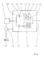
- 2 is a double clutch transmission designated, which can be driven by a drive motor 4 is.
- the double clutch transmission 2 comprises a first partial transmission 6, which is driven by a first clutch 8 can be coupled to the drive motor 4.
- a second sub-transmission 10 is also driven by the second clutch 12 can be coupled to the drive motor. Both sub-transmissions 6, 10 have a common output 14.
- Each of the sub-transmissions 6, 10 has several gear ratios on. Adjacent translation levels in the translation series are not assigned to the same sub-transmission, so with every simple gear change from one is switched to the other sub-transmission.
- a double downshift can be done by a driver for example be requested that he accelerator pedal 16 very quickly depressed by a large amount. Such Operation is by an electronic control device 18 converted into a double downshift command.
Landscapes
- Engineering & Computer Science (AREA)
- Mechanical Engineering (AREA)
- Chemical & Material Sciences (AREA)
- Combustion & Propulsion (AREA)
- Transportation (AREA)
- General Engineering & Computer Science (AREA)
- Automation & Control Theory (AREA)
- Control Of Transmission Device (AREA)
- Hybrid Electric Vehicles (AREA)
Abstract
Description
- 2
- Doppelkupplungsgetriebe
- 4
- Antriebsmotor
- 6
- erstes Teilgetriebe
- 8
- erste Kupplung
- 10
- zweites Teilgetriebe
- 12
- zweite Kupplung
- 14
- Abtrieb
- 16
- Fahrpedal
- 18
- Steuerung
- 20, 22
- Radpaar
- 24, 26
- Radpaar
- 28
- Kupplungshälfte
- 30
- Kupplungshälfte
Claims (4)
- Verfahren zur Steuerung eines Gangstufenwechsels bei einem Fahrzeug mit einem von einem Antriebsmotor (4) antreibbaren Doppelkupplungsgetriebe (2), mit mehreren Gangstufen, bei welchem ein erstes Teilgetriebe (6) durch eine erste Kupplung (8) und ein zweites Teilgetriebe (10) durch eine zweite Kupplung (12) trieblich mit dem Antriebsmotor (4) koppelbar ist und beide Teilgetriebe (6, 10) einen gemeinsamen Abtrieb (14) aufweisen, wobei jedes Teilgetriebe (6, 10) vorzugsweise mehrere Übersetzungsstufen aufweist und zumindest zwei aufeinanderfolgende Gangstufen des Doppelkupplungsgetriebes (2) nicht dem selben Teilgetriebe (6, 10) zugeordnet sind, dadurch gekennzeichnet, dass auf eine Anforderung einer Doppelrückschaltung ein Gangstufenwechsel innerhalb desselben Teilgetriebes (6) erfolgt, ohne dass während des Gangstufenwechsels das andere Teilgetriebe (10) ein Drehmoment vom Antriebsmotor (4) auf den Abtrieb (14) überträgt, und dass das vom Antriebsmotor (4) während des Gangstufenwechsels abgegebene Drehmoment im wesentlichen zum Beschleunigen von antriebsmotorseitigen Drehmassen verwendet wird.
- Verfahren nach Anspruch 1, dadurch gekennzeichnet, dass die Kupplung (8) des Teilgetriebes, innerhalb dessen die Doppelrückschaltung erfolgt, während des Gangstufenwechsels geöffnet ist und erst wieder geschlossen wird, nachdem der Gangstufenwechsel innerhalb des Teilgetriebes (6) abgeschlossen ist.
- Verfahren nach Anspruch 2, dadurch gekennzeichnet, dass der Antriebsmotor (4) während des Gangstufenwechsels unter Last betrieben wird, so dass zum Zeitpunkt, wenn der Gangstufenwechsel innerhalb des Teilgetriebes (6) abgeschlossen ist, eine antriebsmotorseitige Hälfte (28) der Kupplung (8) mindestens dieselbe Drehzahl wie eine teilgetriebeseitige Hälfte (30) der Kupplung (8) aufweist.
- Verfahren nach Anspruch 3, dadurch gekennzeichnet, dass zur Steuerung bzw. Regelung der Motordrehzahl während des Gangstufenwechsels in einer Steuerungseinrichtung (18) eine Motoreingriffsfunktion abgelegt ist, welche den Antriebsmotor (4) derart ansteuert, dass in einer ersten Phase des Gangstufenwechsels ein schneller Drehzahlanstieg erfolgt.
Applications Claiming Priority (2)
| Application Number | Priority Date | Filing Date | Title |
|---|---|---|---|
| DE10151260A DE10151260A1 (de) | 2001-10-17 | 2001-10-17 | Verfahren zur Steuerung eines Doppelkupplungsgetriebes |
| DE10151260 | 2001-10-17 |
Publications (3)
| Publication Number | Publication Date |
|---|---|
| EP1304510A2 true EP1304510A2 (de) | 2003-04-23 |
| EP1304510A3 EP1304510A3 (de) | 2007-02-28 |
| EP1304510B1 EP1304510B1 (de) | 2008-04-09 |
Family
ID=7702801
Family Applications (1)
| Application Number | Title | Priority Date | Filing Date |
|---|---|---|---|
| EP02022823A Revoked EP1304510B1 (de) | 2001-10-17 | 2002-10-12 | Verfahren zur Steuerung eines Doppelkupplungsgetriebes |
Country Status (3)
| Country | Link |
|---|---|
| US (1) | US6698304B2 (de) |
| EP (1) | EP1304510B1 (de) |
| DE (2) | DE10151260A1 (de) |
Cited By (1)
| Publication number | Priority date | Publication date | Assignee | Title |
|---|---|---|---|---|
| WO2015197095A1 (en) * | 2014-06-27 | 2015-12-30 | Volvo Truck Corporation | A method for controlling a drivetrain of a vehicle for improved driver comfort |
Families Citing this family (29)
| Publication number | Priority date | Publication date | Assignee | Title |
|---|---|---|---|---|
| US6941830B2 (en) * | 2000-03-10 | 2005-09-13 | Hitachi, Ltd. | Automatic transmission, dynamo-electric machine, and car |
| GB2415022B (en) * | 2003-04-28 | 2007-07-25 | Volkswagen Ag | Drive transmission |
| US7510506B2 (en) * | 2004-02-10 | 2009-03-31 | Luk Lamellen Und Kupplungabau Beteiligungs Kg | Method and device for controlling gear ratio change in a transmission contained in the drive train of a motor vehicle with gears that can be shifted under power |
| DE102004046558A1 (de) * | 2004-09-24 | 2006-04-06 | Volkswagen Ag | Sensoranordnung und Verfahren zur Steuerung eines automatisierten Doppelkupplungsgetriebes |
| DE102005030987A1 (de) * | 2005-07-02 | 2007-01-18 | Daimlerchrysler Ag | Antriebstrang eines Kraftfahrzeugs |
| US7861613B2 (en) * | 2007-04-17 | 2011-01-04 | Eaton Corporation | Selector mechanism for dual-clutch transmissions |
| US8475336B2 (en) * | 2009-07-30 | 2013-07-02 | GM Global Technology Operations LLC | Hydraulic control system for a dual clutch transmission |
| US8429994B2 (en) | 2009-09-09 | 2013-04-30 | GM Global Technology Operations LLC | Hydraulic control systems for dual clutch transmissions |
| US8225687B2 (en) * | 2009-09-09 | 2012-07-24 | GM Global Technology Operations LLC | Hydraulic control systems for dual clutch transmissions |
| US8403792B2 (en) * | 2009-10-21 | 2013-03-26 | GM Global Technology Operations LLC | Hydraulic control systems for dual clutch transmissions |
| US8192176B2 (en) * | 2009-12-10 | 2012-06-05 | GM Global Technology Operations LLC | Hydraulic fluid supply system having active regulator |
| US8443687B2 (en) * | 2009-12-14 | 2013-05-21 | GM Global Technology Operations LLC | Electro-hydraulic control system for a dual clutch transmission |
| US8887498B2 (en) | 2009-12-18 | 2014-11-18 | Gm Global Technology Operations, Llc | Transmission hydraulic control system having an accumulator bypass valve assembly |
| US8402855B2 (en) * | 2010-01-11 | 2013-03-26 | GM Global Technology Operations LLC | Hydraulic control systems for dual clutch transmissions |
| US8567580B2 (en) * | 2010-01-22 | 2013-10-29 | GM Global Technology Operations LLC | Electro-hydraulic control system for a dual clutch transmission |
| US8234946B2 (en) * | 2010-02-17 | 2012-08-07 | GM Global Technology Operations LLC | Hydraulic control system for a dual clutch transmission |
| US8413777B2 (en) * | 2010-02-17 | 2013-04-09 | GM Global Technology Operations LLC | High efficiency hydraulic transmission control system |
| DE102010018532B3 (de) | 2010-04-27 | 2011-07-07 | GETRAG FORD Transmissions GmbH, 50735 | Verfahren zum Schalten eines Doppelkupplungsgetriebes |
| US8308609B2 (en) * | 2010-06-14 | 2012-11-13 | Ford Global Technologies, Llc | Power-off downshift engagement dampening |
| US8839928B2 (en) | 2010-12-02 | 2014-09-23 | Gm Global Technology Operations, Llc | Electro-hydraulic control system for a dual clutch transmission |
| US8904893B2 (en) | 2010-12-06 | 2014-12-09 | Gm Global Technology Operations, Llc | Method of controlling a dual clutch transmission |
| US8733521B2 (en) | 2010-12-06 | 2014-05-27 | Gm Global Technology Operations | Apparatus for and method of controlling a dual clutch transmission |
| US8738257B2 (en) | 2010-12-08 | 2014-05-27 | Gm Global Technology Operations, Llc | Electro-hydraulic control system and method for a dual clutch transmission |
| US8740748B2 (en) | 2010-12-08 | 2014-06-03 | Gm Global Technology Operations, Llc | Control system and method for a dual clutch transmission |
| US8702564B2 (en) | 2010-12-09 | 2014-04-22 | GM Global Technology Operations LLC | Electro-hydraulic control system and method for a dual clutch transmission |
| DE102011087126B4 (de) * | 2011-11-25 | 2025-06-18 | Zf Friedrichshafen Ag | Steuerungseinrichtung eines Kraftfahrzeugs |
| JP5242820B1 (ja) * | 2012-02-17 | 2013-07-24 | 株式会社エクセディ | ツインクラッチ装置用アクチュエータ |
| US9897182B2 (en) * | 2012-07-24 | 2018-02-20 | Dti Group B.V. | Transmission system |
| JP2014058286A (ja) * | 2012-09-19 | 2014-04-03 | Toyota Motor Corp | ハイブリッド車両の制御装置 |
Citations (1)
| Publication number | Priority date | Publication date | Assignee | Title |
|---|---|---|---|---|
| DE19853824A1 (de) | 1998-11-21 | 2000-05-31 | Getrag Getriebe Zahnrad | Automatisierbarer Kraftfahrzeug-Antriebsstrang sowie Verfahren zum Steuern eines solchen Antriebsstranges |
Family Cites Families (7)
| Publication number | Priority date | Publication date | Assignee | Title |
|---|---|---|---|---|
| US2599801A (en) * | 1949-06-11 | 1952-06-10 | Borg Warner | Double countershaft transmission |
| US4513631A (en) * | 1983-06-16 | 1985-04-30 | General Motors Corporation | Dual input clutch transmission |
| DE4031570C2 (de) * | 1990-10-05 | 1995-10-12 | Daimler Benz Ag | Anordnung zum selbsttätigen Schalten mittels Druckmittel-Hilfskraft eines Mehrwege-Zahnräderwechselgetriebes |
| DE19631983C1 (de) * | 1996-08-08 | 1998-02-12 | Volkswagen Ag | Verfahren zum Schalten eines Doppelkupplungsgetriebes und Doppelkupplungsgetriebe mit Synchronisiereinrichtung |
| DE19711820A1 (de) | 1996-08-08 | 1998-09-24 | Volkswagen Ag | Verfahren zum Schalten eines Doppelkupplungsgetriebes und Doppelkupplungsgetriebe |
| DE19939334A1 (de) * | 1999-08-19 | 2001-03-08 | Daimler Chrysler Ag | Verfahren zum Schalten eines Doppelkupplungsgetriebes und Doppelkupplungsgetriebe |
| DE10165097B3 (de) * | 2000-07-18 | 2015-07-23 | Schaeffler Technologies AG & Co. KG | Doppelkupplungsgetriebe |
-
2001
- 2001-10-17 DE DE10151260A patent/DE10151260A1/de not_active Withdrawn
-
2002
- 2002-09-19 US US10/247,446 patent/US6698304B2/en not_active Expired - Fee Related
- 2002-10-12 DE DE50212054T patent/DE50212054D1/de not_active Expired - Lifetime
- 2002-10-12 EP EP02022823A patent/EP1304510B1/de not_active Revoked
Patent Citations (1)
| Publication number | Priority date | Publication date | Assignee | Title |
|---|---|---|---|---|
| DE19853824A1 (de) | 1998-11-21 | 2000-05-31 | Getrag Getriebe Zahnrad | Automatisierbarer Kraftfahrzeug-Antriebsstrang sowie Verfahren zum Steuern eines solchen Antriebsstranges |
Cited By (1)
| Publication number | Priority date | Publication date | Assignee | Title |
|---|---|---|---|---|
| WO2015197095A1 (en) * | 2014-06-27 | 2015-12-30 | Volvo Truck Corporation | A method for controlling a drivetrain of a vehicle for improved driver comfort |
Also Published As
| Publication number | Publication date |
|---|---|
| EP1304510A3 (de) | 2007-02-28 |
| US6698304B2 (en) | 2004-03-02 |
| US20030074992A1 (en) | 2003-04-24 |
| DE50212054D1 (de) | 2008-05-21 |
| EP1304510B1 (de) | 2008-04-09 |
| DE10151260A1 (de) | 2003-04-30 |
Similar Documents
| Publication | Publication Date | Title |
|---|---|---|
| EP1304510B1 (de) | Verfahren zur Steuerung eines Doppelkupplungsgetriebes | |
| EP0478945B1 (de) | Verfahren zum selbsttätigen Schalten mittels Druckmittel-Hilfskraft eines Mehrwege-Zahnräderwechselgetriebes | |
| EP0517705B1 (de) | Verfahren zum schalten eines stufenwechselgetriebes | |
| DE19939819C1 (de) | Verfahren zum Schalten eines Mehrwege-Zahnräder-Wechselgetriebes | |
| DE3207938C2 (de) | Unter Last schaltbare mechanische Getriebeanordnung | |
| EP1031769B1 (de) | Automatisierter Antriebsstrang für ein Kraftfahrzeug und Verfahren zum Steuern eines Antriebsstranges | |
| DE60207135T2 (de) | Automatikgetriebe | |
| DE3534971A1 (de) | Steuereinrichtung zum selbsttaetigen schalten von stufenwechselgetrieben | |
| WO2007134943A1 (de) | Mehrgruppengetriebe und verfahren zum gangwechsel bei einem mehrgruppengetriebe | |
| DE10349220B4 (de) | Verfahren zum Schalten eines Doppelkupplungsgetriebes eines Kraftfahrzeuges | |
| DE19722480B4 (de) | Gangschaltsteuersystem für ein Automatikgetriebe | |
| EP1357309A2 (de) | Verfahren zur Steuerung eines Anfahrvorgangs mit einem Doppelkupplungsgetriebe | |
| DE102015003407A1 (de) | Kraftfahrzeug mit einem Doppelkupplungsgetriebe | |
| EP0713984A2 (de) | Verfahren zur Bestimmung der Schaltzeit für einen Übersetzungswechsel in einem stufenlosen Getriebe | |
| DE19814569C2 (de) | Zahnräderwechselgetriebe mit einem Zahnräder-Synchronisiergetriebe | |
| EP1002971B1 (de) | Kraftfahrzeug-Antriebsstrang und Verfahren zum Steuern eines Schaltvorganges eines Kraftfahrzeug-Antriebsstranges | |
| DE19845604C5 (de) | Stufengetriebe und Verfahren zum Auslegen eines Ganges eines Stufengetriebes | |
| WO2005008103A1 (de) | Verfahren zum schalten eines doppelkupplungsgetriebes eines kraftfahrzeuges | |
| DE10232832A1 (de) | Verfahren zum Anfahren bei einem Mehrfachkupplungsgetriebe, insbesondere bei einem Doppelkupplungsgetriebe | |
| DE967545C (de) | Zahnraederwechselgetriebe, insbesondere fuer Kraftfahrzeuge mit Verbrennungsmotoren | |
| DE19912315C1 (de) | Zahnräderwechselgetriebe mit zwei in bezug auf den Kraftfluß parallelen Teilgetrieben und Verfahren zum Schalten eines Zahnräderwechselgetriebes | |
| DE102012203582B4 (de) | Verfahren zur Schaltsteuerung eines automatisierten Gruppengetriebes | |
| DE19850546C1 (de) | Mehrgängiges Mehrwege-Zahnräderwechselgetriebe | |
| EP1028270B1 (de) | Automatisierbarer Antriebsstrang für ein Kraftfahrzeug | |
| EP3878672B1 (de) | Verfahren zum betreiben einer hybrid-antriebsbaugruppe mit schaltgetriebe und e-maschine |
Legal Events
| Date | Code | Title | Description |
|---|---|---|---|
| PUAI | Public reference made under article 153(3) epc to a published international application that has entered the european phase |
Free format text: ORIGINAL CODE: 0009012 |
|
| AK | Designated contracting states |
Designated state(s): AT BE BG CH CY CZ DE DK EE ES FI FR GB GR IE IT LI LU MC NL PT SE SK TR |
|
| AX | Request for extension of the european patent |
Extension state: AL LT LV MK RO SI |
|
| PUAL | Search report despatched |
Free format text: ORIGINAL CODE: 0009013 |
|
| AK | Designated contracting states |
Kind code of ref document: A3 Designated state(s): AT BE BG CH CY CZ DE DK EE ES FI FR GB GR IE IT LI LU MC NL PT SE SK TR |
|
| AX | Request for extension of the european patent |
Extension state: AL LT LV MK RO SI |
|
| 17P | Request for examination filed |
Effective date: 20070203 |
|
| AKX | Designation fees paid |
Designated state(s): DE FR GB |
|
| GRAP | Despatch of communication of intention to grant a patent |
Free format text: ORIGINAL CODE: EPIDOSNIGR1 |
|
| RIC1 | Information provided on ipc code assigned before grant |
Ipc: B60W 10/10 20060101ALN20071018BHEP Ipc: F16H 37/06 20060101ALI20071018BHEP Ipc: F16H 61/02 20060101AFI20071018BHEP Ipc: B60W 10/02 20060101ALN20071018BHEP Ipc: B60W 30/18 20060101ALI20071018BHEP Ipc: B60W 10/06 20060101ALN20071018BHEP |
|
| GRAS | Grant fee paid |
Free format text: ORIGINAL CODE: EPIDOSNIGR3 |
|
| GRAA | (expected) grant |
Free format text: ORIGINAL CODE: 0009210 |
|
| AK | Designated contracting states |
Kind code of ref document: B1 Designated state(s): DE FR GB |
|
| REG | Reference to a national code |
Ref country code: GB Ref legal event code: FG4D Free format text: NOT ENGLISH |
|
| REF | Corresponds to: |
Ref document number: 50212054 Country of ref document: DE Date of ref document: 20080521 Kind code of ref document: P |
|
| ET | Fr: translation filed | ||
| PLBI | Opposition filed |
Free format text: ORIGINAL CODE: 0009260 |
|
| PLBI | Opposition filed |
Free format text: ORIGINAL CODE: 0009260 |
|
| 26 | Opposition filed |
Opponent name: LUK LAMELLEN UND KUPPLUNGSBAU BETEILIGUNGS KG Effective date: 20081211 |
|
| PLAX | Notice of opposition and request to file observation + time limit sent |
Free format text: ORIGINAL CODE: EPIDOSNOBS2 |
|
| 26 | Opposition filed |
Opponent name: LUK LAMELLEN UND KUPPLUNGSBAU BETEILIGUNGS KG Effective date: 20081211 Opponent name: GETRAG GETRIEBE- UND ZAHNRADFABRIK HERMANN HAGENME Effective date: 20090107 |
|
| GBPC | Gb: european patent ceased through non-payment of renewal fee |
Effective date: 20081012 |
|
| PLBB | Reply of patent proprietor to notice(s) of opposition received |
Free format text: ORIGINAL CODE: EPIDOSNOBS3 |
|
| PG25 | Lapsed in a contracting state [announced via postgrant information from national office to epo] |
Ref country code: GB Free format text: LAPSE BECAUSE OF NON-PAYMENT OF DUE FEES Effective date: 20081012 |
|
| PGFP | Annual fee paid to national office [announced via postgrant information from national office to epo] |
Ref country code: FR Payment date: 20101020 Year of fee payment: 9 |
|
| PGFP | Annual fee paid to national office [announced via postgrant information from national office to epo] |
Ref country code: DE Payment date: 20101006 Year of fee payment: 9 |
|
| PLAB | Opposition data, opponent's data or that of the opponent's representative modified |
Free format text: ORIGINAL CODE: 0009299OPPO |
|
| RDAF | Communication despatched that patent is revoked |
Free format text: ORIGINAL CODE: EPIDOSNREV1 |
|
| REG | Reference to a national code |
Ref country code: DE Ref legal event code: R064 Ref document number: 50212054 Country of ref document: DE Ref country code: DE Ref legal event code: R103 Ref document number: 50212054 Country of ref document: DE |
|
| R26 | Opposition filed (corrected) |
Opponent name: GETRAG GETRIEBE- UND ZAHNRADFABRIK HERMANN HAGENME Effective date: 20090107 Opponent name: LUK VERMOEGENSVERWALTUNGSGESELLSCHAFT MBH Effective date: 20081211 |
|
| RDAG | Patent revoked |
Free format text: ORIGINAL CODE: 0009271 |
|
| STAA | Information on the status of an ep patent application or granted ep patent |
Free format text: STATUS: PATENT REVOKED |
|
| 27W | Patent revoked |
Effective date: 20110605 |
|
| REG | Reference to a national code |
Ref country code: DE Ref legal event code: R107 Ref document number: 50212054 Country of ref document: DE Effective date: 20111201 |