EP1304491B1 - Elektrisch betätigte Vorrichtung zum selbsttätigen Laufeinstellen und Spielausgleich für ein Zugseil in einem Fahrzeug - Google Patents
Elektrisch betätigte Vorrichtung zum selbsttätigen Laufeinstellen und Spielausgleich für ein Zugseil in einem Fahrzeug Download PDFInfo
- Publication number
- EP1304491B1 EP1304491B1 EP02023190A EP02023190A EP1304491B1 EP 1304491 B1 EP1304491 B1 EP 1304491B1 EP 02023190 A EP02023190 A EP 02023190A EP 02023190 A EP02023190 A EP 02023190A EP 1304491 B1 EP1304491 B1 EP 1304491B1
- Authority
- EP
- European Patent Office
- Prior art keywords
- unit
- flexible cable
- vehicle
- deformation
- cable
- Prior art date
- Legal status (The legal status is an assumption and is not a legal conclusion. Google has not performed a legal analysis and makes no representation as to the accuracy of the status listed.)
- Expired - Lifetime
Links
- 230000005540 biological transmission Effects 0.000 claims abstract description 38
- 230000000694 effects Effects 0.000 claims abstract description 10
- 230000006835 compression Effects 0.000 claims description 8
- 238000007906 compression Methods 0.000 claims description 8
- 238000000034 method Methods 0.000 claims description 6
- 238000012423 maintenance Methods 0.000 claims description 4
- 230000001419 dependent effect Effects 0.000 claims 4
- 230000006870 function Effects 0.000 description 4
- 230000009467 reduction Effects 0.000 description 4
- 230000008859 change Effects 0.000 description 3
- 239000006096 absorbing agent Substances 0.000 description 2
- 238000006243 chemical reaction Methods 0.000 description 2
- 230000000994 depressogenic effect Effects 0.000 description 2
- 238000004519 manufacturing process Methods 0.000 description 2
- 230000007246 mechanism Effects 0.000 description 2
- 238000004904 shortening Methods 0.000 description 2
- 230000002547 anomalous effect Effects 0.000 description 1
- 238000010276 construction Methods 0.000 description 1
- 230000000881 depressing effect Effects 0.000 description 1
- 238000001514 detection method Methods 0.000 description 1
- 230000008030 elimination Effects 0.000 description 1
- 238000003379 elimination reaction Methods 0.000 description 1
- 230000003449 preventive effect Effects 0.000 description 1
- 230000008439 repair process Effects 0.000 description 1
- 230000004044 response Effects 0.000 description 1
Images


Classifications
-
- B—PERFORMING OPERATIONS; TRANSPORTING
- B60—VEHICLES IN GENERAL
- B60T—VEHICLE BRAKE CONTROL SYSTEMS OR PARTS THEREOF; BRAKE CONTROL SYSTEMS OR PARTS THEREOF, IN GENERAL; ARRANGEMENT OF BRAKING ELEMENTS ON VEHICLES IN GENERAL; PORTABLE DEVICES FOR PREVENTING UNWANTED MOVEMENT OF VEHICLES; VEHICLE MODIFICATIONS TO FACILITATE COOLING OF BRAKES
- B60T7/00—Brake-action initiating means
- B60T7/02—Brake-action initiating means for personal initiation
- B60T7/08—Brake-action initiating means for personal initiation hand actuated
- B60T7/10—Disposition of hand control
- B60T7/107—Disposition of hand control with electrical power assistance
-
- B—PERFORMING OPERATIONS; TRANSPORTING
- B60—VEHICLES IN GENERAL
- B60T—VEHICLE BRAKE CONTROL SYSTEMS OR PARTS THEREOF; BRAKE CONTROL SYSTEMS OR PARTS THEREOF, IN GENERAL; ARRANGEMENT OF BRAKING ELEMENTS ON VEHICLES IN GENERAL; PORTABLE DEVICES FOR PREVENTING UNWANTED MOVEMENT OF VEHICLES; VEHICLE MODIFICATIONS TO FACILITATE COOLING OF BRAKES
- B60T13/00—Transmitting braking action from initiating means to ultimate brake actuator with power assistance or drive; Brake systems incorporating such transmitting means, e.g. air-pressure brake systems
- B60T13/74—Transmitting braking action from initiating means to ultimate brake actuator with power assistance or drive; Brake systems incorporating such transmitting means, e.g. air-pressure brake systems with electrical assistance or drive
- B60T13/746—Transmitting braking action from initiating means to ultimate brake actuator with power assistance or drive; Brake systems incorporating such transmitting means, e.g. air-pressure brake systems with electrical assistance or drive and mechanical transmission of the braking action
-
- B—PERFORMING OPERATIONS; TRANSPORTING
- B60—VEHICLES IN GENERAL
- B60T—VEHICLE BRAKE CONTROL SYSTEMS OR PARTS THEREOF; BRAKE CONTROL SYSTEMS OR PARTS THEREOF, IN GENERAL; ARRANGEMENT OF BRAKING ELEMENTS ON VEHICLES IN GENERAL; PORTABLE DEVICES FOR PREVENTING UNWANTED MOVEMENT OF VEHICLES; VEHICLE MODIFICATIONS TO FACILITATE COOLING OF BRAKES
- B60T7/00—Brake-action initiating means
- B60T7/02—Brake-action initiating means for personal initiation
- B60T7/08—Brake-action initiating means for personal initiation hand actuated
- B60T7/10—Disposition of hand control
- B60T7/108—Disposition of hand control with mechanisms to take up slack in the linkage to the brakes
-
- F—MECHANICAL ENGINEERING; LIGHTING; HEATING; WEAPONS; BLASTING
- F16—ENGINEERING ELEMENTS AND UNITS; GENERAL MEASURES FOR PRODUCING AND MAINTAINING EFFECTIVE FUNCTIONING OF MACHINES OR INSTALLATIONS; THERMAL INSULATION IN GENERAL
- F16C—SHAFTS; FLEXIBLE SHAFTS; ELEMENTS OR CRANKSHAFT MECHANISMS; ROTARY BODIES OTHER THAN GEARING ELEMENTS; BEARINGS
- F16C1/00—Flexible shafts; Mechanical means for transmitting movement in a flexible sheathing
- F16C1/10—Means for transmitting linear movement in a flexible sheathing, e.g. "Bowden-mechanisms"
- F16C1/22—Adjusting; Compensating length
- F16C1/226—Adjusting; Compensating length by adjusting the effective length of the sheathing
-
- F—MECHANICAL ENGINEERING; LIGHTING; HEATING; WEAPONS; BLASTING
- F16—ENGINEERING ELEMENTS AND UNITS; GENERAL MEASURES FOR PRODUCING AND MAINTAINING EFFECTIVE FUNCTIONING OF MACHINES OR INSTALLATIONS; THERMAL INSULATION IN GENERAL
- F16C—SHAFTS; FLEXIBLE SHAFTS; ELEMENTS OR CRANKSHAFT MECHANISMS; ROTARY BODIES OTHER THAN GEARING ELEMENTS; BEARINGS
- F16C1/00—Flexible shafts; Mechanical means for transmitting movement in a flexible sheathing
- F16C1/26—Construction of guiding-sheathings or guiding-tubes
- F16C1/262—End fittings; Attachment thereof to the sheathing or tube
-
- F—MECHANICAL ENGINEERING; LIGHTING; HEATING; WEAPONS; BLASTING
- F16—ENGINEERING ELEMENTS AND UNITS; GENERAL MEASURES FOR PRODUCING AND MAINTAINING EFFECTIVE FUNCTIONING OF MACHINES OR INSTALLATIONS; THERMAL INSULATION IN GENERAL
- F16D—COUPLINGS FOR TRANSMITTING ROTATION; CLUTCHES; BRAKES
- F16D13/00—Friction clutches
- F16D13/58—Details
- F16D13/75—Features relating to adjustment, e.g. slack adjusters
- F16D13/752—Features relating to adjustment, e.g. slack adjusters the adjusting device being located in the actuating mechanism arranged outside the clutch
-
- F—MECHANICAL ENGINEERING; LIGHTING; HEATING; WEAPONS; BLASTING
- F16—ENGINEERING ELEMENTS AND UNITS; GENERAL MEASURES FOR PRODUCING AND MAINTAINING EFFECTIVE FUNCTIONING OF MACHINES OR INSTALLATIONS; THERMAL INSULATION IN GENERAL
- F16D—COUPLINGS FOR TRANSMITTING ROTATION; CLUTCHES; BRAKES
- F16D23/00—Details of mechanically-actuated clutches not specific for one distinct type
- F16D23/12—Mechanical clutch-actuating mechanisms arranged outside the clutch as such
-
- F—MECHANICAL ENGINEERING; LIGHTING; HEATING; WEAPONS; BLASTING
- F16—ENGINEERING ELEMENTS AND UNITS; GENERAL MEASURES FOR PRODUCING AND MAINTAINING EFFECTIVE FUNCTIONING OF MACHINES OR INSTALLATIONS; THERMAL INSULATION IN GENERAL
- F16C—SHAFTS; FLEXIBLE SHAFTS; ELEMENTS OR CRANKSHAFT MECHANISMS; ROTARY BODIES OTHER THAN GEARING ELEMENTS; BEARINGS
- F16C2326/00—Articles relating to transporting
- F16C2326/01—Parts of vehicles in general
-
- F—MECHANICAL ENGINEERING; LIGHTING; HEATING; WEAPONS; BLASTING
- F16—ENGINEERING ELEMENTS AND UNITS; GENERAL MEASURES FOR PRODUCING AND MAINTAINING EFFECTIVE FUNCTIONING OF MACHINES OR INSTALLATIONS; THERMAL INSULATION IN GENERAL
- F16C—SHAFTS; FLEXIBLE SHAFTS; ELEMENTS OR CRANKSHAFT MECHANISMS; ROTARY BODIES OTHER THAN GEARING ELEMENTS; BEARINGS
- F16C2361/00—Apparatus or articles in engineering in general
- F16C2361/43—Clutches, e.g. disengaging bearing
Definitions
- the present invention relates to an automatic device for adjusting travel and taking up play and wear for a unit of a motor vehicle, such as a clutch or brake unit, operable by a remote-control member, by means of a flexible-cable transmission, as specified in the preamble to Claim 1.
- the device in a flexible-cable transmission for operating a motorcar clutch.
- This application should not, however, be understood as limiting of the scope of the invention since the device may be used for any unit which is arranged to be operated, by means of a flexible transmission, by a control member situated in a position remote from the unit, not only in a motorcar but also, for example, in a motorcycle.
- the clutch is generally operated by a pedal control of the type shown in Figure 1 of the appended drawings, in which the release position and the travel-limit position of a pedal 25 are indicated A and B, respectively.
- the controls imparted by the driver of the vehicle to the pedal 25 are transmitted to the clutch (not shown) by means of a flexible-cable transmission constituted by a cable 12 slidable inside a sheath 11.
- the total travel of the pedal 25 (indicated c in Figure 1) must allow the clutch disk to be released completely so that the engine shaft is rotationally disconnected from the input shaft of the gearbox.
- Figure 2 shows a characteristic graph for a clutch pedal giving the load on the pedal as a function of the pedal travel.
- Two characteristic points, indicated P1 and P2 identify the disengagement-travel value which corresponds to the complete release of the clutch disk, and the total-travel value, respectively.
- the disengagement travel depends substantially on the tolerance chain of the components of the control transmission.
- the total travel depends basically on the adjustment of the control, so that, if an infinitely precise adjustment method were available, it would therefore be equal for all cars produced. In reality, the total travel is also subject to variations due to the following factors:
- an adjustment device 62 advantageously usable in the flexible-cable transmission for operating a motorcar parking brake, comprises substantially:
- the spring 86 tends to extend, causing the radial teeth 82 of the nut 66 to mesh with the radial teeth 84 of the sleeve 72.
- the sleeve 72 When the sleeve 72 is set in rotation by the actuator unit, it therefore brings with it the nut 66 and the insert 68, which rotates, moving axially along the end portion 70 of the sheath (which is prevented from rotating) until the radial teeth 82 and 84 are disconnected when the correct distance between the nut 66 and the end member 64 has been reached.
- a disadvantage of a device of this type is the fact that it enables the travel to be adjusted in only one direction to compensate solely for the effect of wear. Moreover, there is no control system which can monitor the adjustment.
- a flexible-cable transmission for operating a unit 3 (such as, in particular, a clutch) comprises a flexible cable 1 which, for part of its length, is arranged slidably in a sheath 2 having a first fixed end 12 and a second end 13 movable axially in both directions between two limit positions. Translation of the end 13 of the sheath 2 is brought about by an actuator 200 under the control of a computer 40.
- the transmission control makes use of two position sensors 50 and 51 for detecting the position of the clutch pedal 8, of a position sensor 60 for detecting the position of the end 13 of the sheath 2, and of a force sensor 80 for detecting the tensile force in the flexible cable 1.
- the force sensor 80 detects a residual tensile force in the cable 1, clearly due to wear of the clutch disk, the actuator 200 brings about movement of the end 13 of the sheath, under the control of the computer 40, until this residual force is cancelled out.
- an adjustment device of this type is complex and expensive since it uses a large number of sensors including, in particular, a force sensor.
- the object of the present invention is to provide an automatic device for adjusting travel and taking up play and wear for a flexible-cable transmission which can transmit to a unit of a motor vehicle, such as a clutch unit or a braking unit, the controls imparted by the driver by means of a remote-control member, which device can eliminate the disadvantages of the prior art discussed above.
- the device should be able to perform the following functions:
- the invention also proposes to provide a device which is easy to manufacture and to fit, which has a compact structure, and which requires a minimal number of sensors, eliminating, in particular, the need to use position sensors on the pedal or force sensors on the flexible cable.
- a first embodiment provides for the mounting of the automatic adjustment device on the sheath in which the flexible cable slides.
- a second preferred embodiment provides for the mounting of the device directly on the flexible cable, preferably in the vicinity of the remote-control member or in the vicinity of the operating member within the unit to be operated.
- an automatic adjustment device is arranged, according to a first embodiment of the invention, to cooperate with the sheath 11.
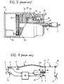
- the device 10 comprises, first of all, an outer casing 13 having a first essentially cylindrical, tubular portion 13a through the entire length of which the flexible cable 12 extends, and a second portion 13b disposed adjacent to the first and having a suitable, substantially parallelepipedal shape, for housing an actuator unit 30 (described further below).
- An axial face of the tubular portion 13a has an opening 14 through which an end portion 11a of the sheath 11 can pass.
- the portion 13a is closed by an abutment element 15 in the form of a cover ( Figure 6).
- the abutment element 15 is provided with a cylindrical, tubular appendage 15a which is coaxial with the portion 13a and in which there is provided a hole 16 through which the cable 12 can pass.
- the device 10 co-operates, at one end, with the sheath 11 in the region of the opening 14 and, at the axially opposite end, with a reaction restraint provided by a fixed portion of the vehicle, reacting on the appendage 15a of the abutment element 15.
- This reaction restraint may also be provided by another end of the sheath if the device 10 is mounted in the flexible transmission in an intermediate position between the pedal 25 and the clutch 26.
- the flexible cable 12 passes through the tubular portion 13a throughout the length thereof, whereas the sheath 11 enters only part of the portion 13a, through the opening 14.
- the end portion 11a of the sheath 11 in the region of the opening 14 is locked in a coaxial, cylindrical cavity of a guide sleeve 17 which is partially housed so as to be slidable axially in an internal cylindrical cavity 18 of the portion 13a.
- the spring 24 thus urges, at one end, against the abutment element 15 which, as stated above, may be either clamped to a fixed portion of the motor vehicle or fixed to the end of a second portion of sheath.
- the spring 24 acts on the assembly constituted by the cup 23, the shock-absorber ring 22, the slider 21, the nut screw 20, the screw 19, the guide sleeve 17, and the end portion 11a of the sheath 11.
- the spring 24 has the function of keeping the flexible-cable transmission system in equilibrium by reacting resiliently to the compression force which the sheath 11 exerts on the abutment element 15 via the various components interposed between its end portion 11a and the cup 23, in response to the tensile force in the flexible cable 12.
- the elastic characteristics of the spring 24 are set so as to assure a given preloading force on the clutch disk in rest conditions, that is, when no pressure is exerted on the clutch pedal.
- the portion 13b of the casing 13 houses the actuator unit 30 which, as will be explained further below, is arranged to move the end portion 11a of the sheath 11 axially by means of the system comprising the screw 19 and the nut screw 20, so as to compensate for the above-described effects of settling and wear.
- the actuator unit 30 comprises an electric motor 31 which can set in rotation the nut screw 20, preferably by means of a reduction-gear unit 32.
- An electronic control unit 33 ( Figure 6) is arranged to receive as inputs, from one or more position sensors 34, signals indicative of the position of the cup 23, and hence of the deformation of the spring 24, and to power the electric motor 31 in dependence on these signals.
- the consequence of settling in the control mechanism of the clutch unit is a lengthening of the flexible cable 12.
- the spring 24 consequently also lengthens and, by pushing against the various components interposed between the cup 23 and the guide sleeve 17, moves the end portion 11a of the sheath 11 axially towards the outside of the device.
- the movement of the cup 23 is detected by the position sensors 34 which transmit a corresponding signal to the electronic control unit 33 of the actuator unit 30, which powers the electric motor 31 in order to set in rotation the nut screw 20.
- This rotation is controlled by the electronic control unit 33 in a manner such as to move the screw 19, and hence the sheath portion 11a (restrained on the guide sleeve 17), towards the outside of the device until the flexible transmission is brought back into equilibrium with the spring 24 in the original preloading position.
- the electronic control unit 33 is arranged to inhibit the operation of the device when the change in the length of the spring 24, either in the lengthening direction (settling) or in the shortening direction (wear), is greater than a given limit value for the intervention of the device.
- the control unit 33 If the spring 24 is shortened by more than this limit value as a result of the fact that the driver is depressing the clutch pedal, and the flexible cable 12 is thus subjected to a tensile force greater than that which would result from wear of the clutch disk, the control unit 33 therefore detects this condition by means of the sensors 34 and consequently prevents the electric motor 31 from operating.
- the adjustment device thus remains inactive, acting as a rigid body which does not cause the length of the flexible transmission to change.
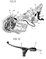
- a second preferred embodiment of the present invention provides for the automatic adjustment device 10 to be mounted directly on the flexible cable 12, advantageously in the vicinity of the pedal 25 (position I of Figure 9) or in the vicinity of the clutch unit 26 (position II of Figure 9).
- the operation of the device according to this further embodiment is similar to that described above, with the difference that, in this case, the adjustment is performed by varying the length of the flexible cable 12 instead of the sheath 11.
- the automatic adjustment device 10 comprises an essentially cylindrical outer casing 13 to one end of which is fixed an abutment element 15 having a through-hole 16 through which an end portion 12a of the flexible cable 12 is introduced.
- a head element 23' clamped onto the end portion 12a of the cable is movable axially in a cylindrical cavity 18 of the casing 13.
- a compression spring 24 is interposed axially between the abutment element 15 and the head element 23', the stiffness of the spring 24 being set so as to keep the flexible transmission in equilibrium with a preloading force of given value on the clutch disk.
- This movement is detected by one or more position sensors 34 which send a corresponding signal to an electronic control unit 33, which is arranged to operate an actuator 30 in dependence on the signals received from the sensors 34.
- the actuator 30, which comprises substantially an electric motor 31 and a geared reduction unit 32, is arranged to set in rotation a nut screw 20 of a male-and-female screw system.
- the rotation of the nut screw 20 causes a screw 19 to move axially in one of the two directions (according to the direction of rotation), the screw 19 passing through an opening 14 formed in the face of the casing 13 axially opposite that having the opening 16, and being connected, directly or indirectly, to an operating lever 26a of the clutch 26, or to the pedal 25, if the device 10 is mounted in the vicinity of the clutch, or of the pedal, respectively.
- the axial movement of the screw 19 which varies the relative distance between the screw and the end 12a of the flexible cable 12, is brought about by the control unit 33 by means of the actuator 30 in dependence on the signals transmitted by the sensors 34, with the objective of keeping the spring 24 in the original conditions of equilibrium (which can ensure the given value of the preloading force on the clutch disk), compensating for the lengthening or shortening of the spring caused by settling of the flexible transmission or by wear of the clutch disk, respectively.
- the automatic adjustment device 10 is provided with electrical connection means (not shown) for the power supply of the electronic control unit 33 and of the electric motor 31.
- the electronic control unit 33 also comprises memory means for storing all of the data useful for the correct operation of the device, such as, for example, the limit values of the movement of the spring 24 in the two directions, beyond which the control unit inhibits the operation of the device.
- the automatic device 10 can advantageously store all of the adjustments performed in the wear-compensation direction in order to be able to provide the driver (for example, by means of a suitable warning light on the dashboard) with an indication of the state of wear of the clutch disk, usable for the purposes of preventive maintenance of the vehicle.
- the automatic adjustment device 10 is mounted in the flexible transmission for operating the clutch unit 26, in one of the two positions I, II described above ( Figure 9), with the compensation screw 19 in the most extended position, and then it is connected to the electrical system of the vehicle with the ignition key in the "off" position. Movement of the key to the "on” position starts a first automatic adjustment step during which the device puts the flexible cable 12 under tension with a predetermined force (for example, 35 N) in order to compensate for the play present in the flexible transmission. After a certain number of operations of the pedal 25, the ignition key is returned to the "off" position.
- a predetermined force for example, 35 N
- the device then performs a second automatic adjustment step, reestablishing the condition in which the cable 12 is preloaded with a predetermined tensile force (for example, 35N).
- a predetermined tensile force for example, 35N
- the automatic device 10 performs the adjustment of the travel to compensate for the effect of settling and wear solely when the ignition key is in the "off" position and when the clutch pedal is in the released position.
- a predetermined period of time for example, 3s
- the electronic control unit 33 receives, as an input, the position signal coming from the sensor 34 and compares its instantaneous value with the predetermined reference value. In dependence on the difference between these two values (error), the control unit 33 determines the magnitude and direction of the axial movement to be imparted to the screw 19 in order to compensate for this error, returning the system to predetermined equilibrium conditions, and sends a corresponding control signal to the electric motor 31.
- the adjustment device Upon completion of the adjustment step, the adjustment device returns to the "stand-by" condition.
- the automatic adjustment device remains inactive; the device performs the adjustment only when a certain period of time (for example, 3s) has elapsed after the pedal has been released, and then returns to the "stand-by" condition.
- the exertion of a pressure on the clutch pedal can be detected by the control unit 33 of the device substantially in two ways.
- the first way relates to the situation in which the pressure on the pedal is great enough to produce a tensile force in the flexible cable 12 such as to compress the spring 24 by more than the limit value beyond which the operation of the adjustment device is inhibited.
- the second way enables the pressure on the pedal to be detected, even when it is so small as to bring about a compression of the spring within the adjustment limit.
- the device is in fact advantageously arranged, according to the invention, to perform a series of readings of the position of the spring, within the period of time between the switching-off of the engine and the start of the adjustment.
- control unit recognizes that it is not settling or wear that has taken place but that a pressure is being applied to the pedal (for example, owing to the fact that, having switched off the engine, the driver has remained in the vehicle in the driving position and, perhaps without noticing, still has his foot on the clutch pedal), and consequently prevents the adjustment.
- the compensation screw 19 can be moved to the most extended position by sending a specific command to the device.
- This command can be imparted by serial connection to an external electronic control unit or by a predetermined procedure comprising, for example, the steps of disconnection and subsequent connection of the power supply and the execution of a certain number of operating cycles of the remote-control member.
- an automatic adjustment device according to the invention in the flexible-cable control system of a motorcycle clutch is illustrated schematically in Figure 10, in which parts and elements identical or corresponding to those shown in Figures 5 to 9 have been attributed the same reference numerals.
- the remote-control member is represented by a lever 25 disposed on the handlebar of the motorcycle (not shown) and the automatic adjustment device 10 is fitted directly on the flexible cable 12, in the vicinity of the lever 25.
Landscapes
- Engineering & Computer Science (AREA)
- General Engineering & Computer Science (AREA)
- Mechanical Engineering (AREA)
- Transportation (AREA)
- Health & Medical Sciences (AREA)
- Oral & Maxillofacial Surgery (AREA)
- Mechanical Control Devices (AREA)
- Mechanical Operated Clutches (AREA)
- Flexible Shafts (AREA)
- Braking Arrangements (AREA)
- Vehicle Body Suspensions (AREA)
- Braking Elements And Transmission Devices (AREA)
- Harvester Elements (AREA)
- Control Of Position, Course, Altitude, Or Attitude Of Moving Bodies (AREA)
Claims (26)
- Automatische Vorrichtung (10) zum Einstellen des Hubs sowie für die Aufnahme von einem Spiel und von einem Verschleiß bei einer Kraftübertragung mit einem flexiblen Kabel (12) und einer Hülle (11), um zu einer Einheit (26) eines Kraftfahrzeugs, beispielsweise zu einer Kupplungs- oder Bremseinheit, jene Steuerungen zu übertragen, die der Lenker des Fahrzeugs mit Hilfe eines Fernsteuerelements (25) ausführt, wobei die Vorrichtung dadurch gekennzeichnet ist, dass sie enthält:eine elastische Einrichtung (24), die direkt oder indirekt mit einem Endteil (11a) der Hülle (11) verbunden und so angeordnet ist, dass sie als Ergebnis von Änderungen in der Länge der Hülle (11) und/oder in der Zugkraft im flexiblen Kabel (12) verformt wird, die von einem Nachlassen der Kraftübertragung und/oder von einem Verschleiß der Einheit (26) stammen, die betätigt werden soll,eine Sensoreinrichtung (34), um die Verformung der elastischen Einrichtung (24) abzutasten und ein Signal bereit zu stellen, das die Verformung anzeigt,eine Prozessoreinrichtung (33), um das Verformungssignal zu empfangen und zu verarbeiten, um ein Steuersignal zu erzeugen,eine Stelleinrichtung (30), um das Steuersignal zu empfangen und ein bewegbares Element (19) zu bewegen, an dem der Endteil (11a) der Hülle (11) befestigt ist, um die Auswirkung von einem Nachlassen und/oder von einem Verschleiß durch das Einstellen der Länge der Kraftübertragung zu kompensieren und die Größe der Zugkraft im Kabel (12) zu steuern.
- Automatische Vorrichtung (10) zum Einstellen des Hubs sowie für die Aufnahme von einem Spiel und von einem Verschleiß bei einer Kraftübertragung mit einem flexiblen Kabel (12), um zu einer Einheit (26) eines Kraftfahrzeugs, beispielsweise zu einer Kupplungs- oder Bremseinheit, jene Steuerungen zu übertragen, die der Lenker des Fahrzeugs mit Hilfe eines Fernsteuerelements (25) ausführt, wobei die Vorrichtung dadurch gekennzeichnet ist, dass sie enthält:eine elastische Einrichtung (24), die direkt oder indirekt mit einem Endteil (12a) des flexiblen Kabels (12) verbunden und so angeordnet ist, dass sie als Ergebnis von einer Änderung in der Zugkraft im Kabel (12) verformt wird, die von einem Nachlassen des Kraftübertragungssystems und/oder von einem Verschleiß in der Einheit (26) stammt, die betätigt werden soll,eine Sensoreinrichtung (34), um die Verformung der elastischen Einrichtung (24) abzutasten und ein Signal bereit zu stellen, das die Verformung anzeigt,eine Prozessoreinrichtung (33), um das Verformungssignal zu empfangen und zu verarbeiten, um ein Steuersignal zu erzeugen,eine Stelleinrichtung (30), um das Steuersignal zu empfangen und ein bewegbares Element (19) zu bewegen, das zwischen zumindest einem Teil des flexiblen Kabels (12) und dem Fernsteuerelement (25) oder der Einheit (26) liegt, die betätigt werden soll, um die Auswirkung von einem Nachlassen und/oder von einem Verschleiß durch das Einstellen der Länge der Kraftübertragung zu kompensieren und die Größe der Zugkraft im Kabel (12) zu steuern.
- Vorrichtung gemäß Anspruch 1 oder 2, dadurch gekennzeichnet, dass die Prozessoreinrichtung (33) so aufgebaut ist, dass sie die Stelleinrichtung (30) so steuert, dass die Zugkraft im flexiblen Kabel (12) auf einem konstanten und vorgegebenen Wert gehalten wird, um eine konstante und vorgegebene Vorspannungskraft auf die Einheit (26) sicher zu stellen, die betätigt werden soll.
- vorrichtung gemäß irgendeinem der bisherigen Ansprüche, dadurch gekennzeichnet, dass die Vorrichtung ein Gehäuse (13) enthält, in dem die elastische Einrichtung (24), die Sensoreinrichtung (34), die Prozessoreinrichtung (33) und die Stelleinrichtung (30) untergebracht sind.
- Vorrichtung gemäß Anspruch 4, wenn dieser vom Anspruch 1 abhängt, dadurch gekennzeichnet, dass das Gehäuse (13) eine erste Öffnung (16), durch die das flexible Kabel (12) eingeführt wird, sowie eine zweite Öffnung (14) besitzt, durch die das Kabel (12) und das bewegbare Element (19) mit dem Endteil (11a) der Hülle (11) vorspringen.
- Vorrichtung gemäß Anspruch 4, wenn dieser vom Anspruch 2 abhängt, dadurch gekennzeichnet, dass das Gehäuse (13) eine erste Öffnung (16), durch die der Endteil (12a) des flexiblen Kabels (12) eingeführt wird, sowie eine zweite Öffnung (14) besitzt, durch die das bewegbare Element (19) vorspringt.
- Vorrichtung gemäß Anspruch 5 oder 6, dadurch gekennzeichnet, dass die erste und die zweite Öffnung (16, 14) koaxial zueinander liegen.
- Vorrichtung gemäß Anspruch 2, dadurch gekennzeichnet, dass die Vorrichtung an einer ersten Stelle (I) in der Nähe des Fernsteuerelements (25) befestigt werden kann, wobei sie so ausgerichtet ist, dass das bewegbare Element (19) direkt oder indirekt mit dem Steuerelement (25) verbunden werden kann.
- Vorrichtung gemäß Anspruch 2, dadurch gekennzeichnet, dass die Vorrichtung an einer zweiten Stelle (II) in der Nähe jener Einheit (26) befestigt werden kann, die betätigt werden soll, wobei sie so ausgerichtet ist, dass das bewegbare Element (19) direkt oder indirekt mit einem Betätigungshebel (26a) der Einheit (26) verbunden werden kann.
- Vorrichtung gemäß irgendeinem der bisherigen Ansprüche, dadurch gekennzeichnet, dass das bewegbare Element (19) mit einem Gewinde versehen ist.
- Vorrichtung gemäß Anspruch 10, dadurch gekennzeichnet, dass das bewegbare Element (19) eine Schnecke ist, die axial mit Hilfe einer Mutter (20) bewegt werden kann, die von der Stelleinrichtung (30) direkt oder indirekt in Drehung versetzt werden kann.
- Vorrichtung gemäß Anspruch 11, dadurch gekennzeichnet, dass die Schnecke (19) rohrförmig mit einer koaxialen Durchgangsöffnung ausgebildet ist, durch die das flexible Kabel (12) verläuft.
- Vorrichtung gemäß Anspruch 1 oder 2, dadurch gekennzeichnet, dass die elastische Einrichtung eine Druckfeder. (24) enthält, die in einer Stellung im Wesentlichen koaxial zum flexiblen Kabel (12) liegt.
- Vorrichtung gemäß Anspruch 4 und 13, wenn diese vom Anspruch 1 abhängen, dadurch gekennzeichnet, dass die Druckfeder (24) an einem Ende auf einem Auflagerelement (15) aufliegt, das am Gehäuse (13) befestigt ist, und am axial gegenüber liegenden Ende indirekt mit dem Endteil (11a) der Hülle (11) verbunden ist.
- Vorrichtung gemäß Anspruch 4 und 13, wenn diese vom Anspruch 2 abhängen, dadurch gekennzeichnet, dass die Druckfeder (24) an einem Ende auf einem Auflagerelement (15) aufliegt, das am Gehäuse (13) befestigt ist, und am axial gegenüber liegenden Ende mit dem Endteil (12a) des flexiblen Kabels (12) verbunden ist.
- Vorrichtung gemäß Anspruch 14, dadurch gekennzeichnet, dass das Auflagerelement (15) an einem ortsfesten Teil des Fahrzeugs angebracht ist.
- Vorrichtung gemäß Anspruch 14, dadurch gekennzeichnet, dass das Auflagerelement (15) mit einem Ende eines Hüllenteils (11) verbunden ist, auf den nicht die Druckfeder (24) wirkt.
- Vorrichtung gemäß irgendeinem der bisherigen Ansprüche, dadurch gekennzeichnet, dass die Prozessoreinrichtung (33) so aufgebaut ist, dass sie eine automatische Einstellung der flexiblen Kraftübertragung für die Betätigung der Einheit (26) sowohl während der Befestigung am Fahrzeug, als auch während der normalen Verwendung des Fahrzeugs vornimmt.
- Vorrichtung gemäß irgendeinem der bisherigen Ansprüche, dadurch gekennzeichnet, dass die Prozessoreinrichtung (33) so aufgebaut ist, dass sie das bewegbare Element (19) in eine Grenzstellung der Auslenkung bewegt, um die Demontage des flexiblen Kabels (12) im Falle von Wartungsvorgängen zu erleichtern, die an der Einheit (26) ausgeführt werden.
- Vorrichtung gemäß irgendeinem der bisherigen Ansprüche, dadurch gekennzeichnet, dass die Prozessoreinrichtung (33) so aufgebaut ist, dass sie die automatische Einstellung während der normalen Verwendung des Fahrzeugs mit folgenden Schritten vornimmt:wenn ein vorgegebenes Zeitintervall (beispielsweise 3 Sekunden) vergangen ist, nachdem der Zündschlüssel in die Stellung "AUS" geschaltet wurde, wobei sich das Fernsteuerelement (25) in der freigegebenen Stellung befindet, setzt die Prozessoreinrichtung (33) der Vorrichtung (10) die Stelleinrichtung (30) für ein kurzes Zeitintervall (beispielsweise 1 Sekunde) in Betrieb, um die Auswirkung von einem Nachlassen und/oder von einem Verschleiß zu kompensieren, wodurch ein vorgegebener Wert der Zugkraft im flexiblen Kabel (12) sicher gestellt wird, unddie Vorrichtung (10) kehrt in den Bereitschaftszustand zurück, in dem das bewegbare Element (19) in jener Stellung verriegelt gehalten wird, die bei einem Abschluss des Einstellschritts erreicht wurde.
- Vorrichtung gemäß irgendeinem der bisherigen Ansprüche, dadurch gekennzeichnet, dass dann, wenn der Zündschlüssel des Fahrzeugs in die Stellung "EIN" geschaltet und/oder das Fernsteuerelement (25) betätigt wird, die Prozessoreinrichtung (33) so aufgebaut ist, dass ein Betrieb der Vorrichtung (10) verhindert wird.
- Vorrichtung gemäß irgendeinem der bisherigen Ansprüche, dadurch gekennzeichnet, dass die Prozessoreinrichtung (33) so aufgebaut ist, dass sie die Einstellung nur dann ausführt, wenn die Verformung der elastischen Einrichtung (24) innerhalb von vorgegebenen Grenzen liegt, wobei ein Überschreiten dieser Grenzen die Betätigung des Fernsteuerelements (25) anzeigt.
- Vorrichtung gemäß Anspruch 22, dadurch gekennzeichnet, dass die Vorrichtung weiters eine Speichereinrichtung enthält, um die vorgegebenen Grenzwerte der Verformung der elastischen Einrichtung (24) zu speichern.
- Vorrichtung gemäß Anspruch 23, dadurch gekennzeichnet, dass die Prozessoreinrichtung (33) so aufgebaut ist, dass:Daten, die die Verformung der elastischen Einrichtung (24) anzeigen, mit der Sensoreinrichtung (34) zu verschiedenen Zeitpunkten innerhalb des Zeitintervalls zwischen dem Schalten des Zündschlüssels in die Stellung "AUS" und dem Beginn des Einstellschritts erfasst werden,Daten der Verformung, die auf diese Weise erfasst werden, in der Speichereinrichtung gespeichert werden,jeder Datenwert der Verformung mit dem Datenwert der Verformung verglichen wird, der zum Zeitpunkt unmittelbar vorher erfasst wurde, unddie Einstellung verhindert wird, wenn der Unterschied zwischen den oben erwähnten beiden Datenwerten der Verformung größer als ein vorgegebener Fehlerschwellenwert ist.
- Vorrichtung gemäß Anspruch 23, im Besonderen für eine Verwendung in einer Kraftübertragung mit einem flexiblen Kabel zur Betätigung einer Kupplung (26), dadurch gekennzeichnet, dass die Prozessoreinrichtung (33) so aufgebaut ist, um die Größen der Einstellungen zu speichern, die in Richtung einer Kompensation von einem Verschleiß ausgeführt werden, um dem Lenker oder einer Bedienungsperson, die eine Wartung des Fahrzeugs durchführen soll, eine Anzeige über den letzten Stand des Verschleißes der Kupplungsscheibe (26) zu liefern.
- Verfahren zum Einstellen des Hubs in einer Kraftübertragung mit einem flexiblen Kabel (12), um zu einer Einheit (26) eines Kraftfahrzeugs, beispielsweise einer Kupplungs- oder Bremseinheit, jene Steuerungen zu übertragen, die vom Lenker des Fahrzeugs mit Hilfe eines Fernsteuerelements (25) ausgeführt werden, wobei die Einstellung mit einer automatischen Vorrichtung (10) gemäß irgendeinem der bisherigen Ansprüche vorgenommen wird, wobei das Verfahren dadurch gekennzeichnet ist, dass es folgende Schritte enthält:Befestigen der Vorrichtung (10), wobei sich das bewegbare Element (19) in seiner maximalen Auslenkung befindet, an einer Zwischenstelle der Kraftübertragung zwischen dem Fernsteuerelement (25) und jener Einheit (26), die betätigt werden soll,Verbinden der Vorrichtung (10) mit dem elektrischen System des Fahrzeugs, wobei der Zündschlüssel nicht eingesteckt ist,Ausführen mit Hilfe der Vorrichtung (10), nachdem der Zündschlüssel des Fahrzeugs eingesteckt und in die Stellung "EIN" geschaltet wurde, eines ersten Einstellschritts, bei dem das flexible Kabel (12) mit einer Kraft, die einen vorgegebenen Wert besitzt, unter Zug gesetzt wird, um jenes Spiel zu kompensieren, das in der Kraftübertragung vorhanden ist,Rückführen des Zündschlüssels in die Stellung "AUS", nachdem eine bestimmte Anzahl von Betätigungen des Fernsteuerelements (25) vorgenommen wurden, undAusführen mit Hilfe der Vorrichtung (10) eines zweiten automatischen Einstellschritts, wenn ein minimales Zeitintervall (beispielsweise 1 Sekunde) vergangen ist, wobei das Fernsteuerelement (25) freigegeben wurde, um das flexible Kabel (12) mit dem vorgegebenen Kraftwert wieder unter Zug zu setzen.
Applications Claiming Priority (2)
| Application Number | Priority Date | Filing Date | Title |
|---|---|---|---|
| ITTO20010986 | 2001-10-17 | ||
| IT2001TO000986A ITTO20010986A1 (it) | 2001-10-17 | 2001-10-17 | Dispositivo automatico di regolazione della corsa e di recupero del gioco e dell'usura per gruppi azionabili mediante trasmissione a cavo fl |
Publications (2)
| Publication Number | Publication Date |
|---|---|
| EP1304491A1 EP1304491A1 (de) | 2003-04-23 |
| EP1304491B1 true EP1304491B1 (de) | 2005-11-02 |
Family
ID=11459265
Family Applications (1)
| Application Number | Title | Priority Date | Filing Date |
|---|---|---|---|
| EP02023190A Expired - Lifetime EP1304491B1 (de) | 2001-10-17 | 2002-10-16 | Elektrisch betätigte Vorrichtung zum selbsttätigen Laufeinstellen und Spielausgleich für ein Zugseil in einem Fahrzeug |
Country Status (6)
| Country | Link |
|---|---|
| EP (1) | EP1304491B1 (de) |
| AT (1) | ATE308686T1 (de) |
| DE (1) | DE60207030T2 (de) |
| DK (1) | DK1304491T3 (de) |
| ES (1) | ES2251556T3 (de) |
| IT (1) | ITTO20010986A1 (de) |
Cited By (1)
| Publication number | Priority date | Publication date | Assignee | Title |
|---|---|---|---|---|
| CN105465216A (zh) * | 2014-09-25 | 2016-04-06 | 舍弗勒技术股份两合公司 | 离合器操作系统 |
Families Citing this family (4)
| Publication number | Priority date | Publication date | Assignee | Title |
|---|---|---|---|---|
| EP1619398B1 (de) * | 2004-07-23 | 2007-05-02 | Siemens Aktiengesellschaft | Stelleinrichtung, insbesondere Kraftfahrzeugfeststellbremse |
| US20060272444A1 (en) * | 2005-06-03 | 2006-12-07 | Ray Cockerham | Electromechanical cable actuator assembly controller |
| US9726216B2 (en) * | 2013-02-04 | 2017-08-08 | Shimano Inc. | Cable adjusting unit |
| DE102019134460A1 (de) * | 2019-12-16 | 2021-06-17 | Fte Automotive Gmbh | Kupplungsaktuator und Verfahren zur Ansteuerung eines Kupplungsaktuators |
Family Cites Families (7)
| Publication number | Priority date | Publication date | Assignee | Title |
|---|---|---|---|---|
| FR2652549B1 (fr) * | 1989-09-29 | 1994-09-30 | Valeo | Timonerie de transmission de forces pour vehicules automobiles. |
| US4987793A (en) * | 1990-01-04 | 1991-01-29 | Babcock Industries, Inc. | Cable control system with adjustment device |
| US5167166A (en) * | 1991-10-11 | 1992-12-01 | Teleflex Incorporated | Rack and roller core element adjust |
| GB9203278D0 (en) * | 1992-02-14 | 1992-04-01 | Acco Cables Controls Ltd | Control cable adjuster devices |
| US5884433A (en) * | 1996-03-19 | 1999-03-23 | Mitsui Kinzoku Kogyo Kabushiki Kaisha | Tension adjusting apparatus for use in vehicle door powered sliding device |
| DE19800858C2 (de) * | 1997-09-18 | 2003-06-18 | Kuester & Co Gmbh | Einstellvorrichtung zum Längenausgleich für einen Betätigungszug |
| FR2797244B1 (fr) * | 1999-08-04 | 2002-03-22 | Lemforder Nacam Sa | Direction de vehicule automobile a correction automatique de trajectoire |
-
2001
- 2001-10-17 IT IT2001TO000986A patent/ITTO20010986A1/it unknown
-
2002
- 2002-10-16 EP EP02023190A patent/EP1304491B1/de not_active Expired - Lifetime
- 2002-10-16 DK DK02023190T patent/DK1304491T3/da active
- 2002-10-16 AT AT02023190T patent/ATE308686T1/de not_active IP Right Cessation
- 2002-10-16 ES ES02023190T patent/ES2251556T3/es not_active Expired - Lifetime
- 2002-10-16 DE DE60207030T patent/DE60207030T2/de not_active Expired - Fee Related
Cited By (1)
| Publication number | Priority date | Publication date | Assignee | Title |
|---|---|---|---|---|
| CN105465216A (zh) * | 2014-09-25 | 2016-04-06 | 舍弗勒技术股份两合公司 | 离合器操作系统 |
Also Published As
| Publication number | Publication date |
|---|---|
| DE60207030T2 (de) | 2006-04-20 |
| ATE308686T1 (de) | 2005-11-15 |
| DK1304491T3 (da) | 2006-03-27 |
| ITTO20010986A1 (it) | 2003-04-17 |
| EP1304491A1 (de) | 2003-04-23 |
| ES2251556T3 (es) | 2006-05-01 |
| DE60207030D1 (de) | 2005-12-08 |
Similar Documents
| Publication | Publication Date | Title |
|---|---|---|
| US5928110A (en) | Power train with automated clutch for use in motor vehicles | |
| US5954178A (en) | Apparatus for actuating an aggregate in the power train of a motor vehicle | |
| CN108291593B (zh) | 盘式制动器的电磨损补偿调整装置、相应的盘式制动器和用于测量、调节气隙和测量磨损的方法 | |
| EP0872670B1 (de) | Steuerung für Servo-Schaltung | |
| US6701797B2 (en) | Parking assembly | |
| US5141070A (en) | Engine loading device with electric and mechanical control of a throttle valve | |
| JP5752695B2 (ja) | 電子コントロールされる駐車・ブレーキ・システム | |
| EP1375294B1 (de) | Kraftfahrzeuglenkeinrichtung | |
| US5417624A (en) | Actuating means for a motor vehicle locking brake | |
| JP2010107039A (ja) | クラッチ | |
| US7648006B2 (en) | Regulating device for a motor vehicle parking brake | |
| EP1056961A1 (de) | Verfahren, methode und system zur steuerung einer elektrisch betriebenen parkbremse | |
| JP2001514597A (ja) | 車両用の駐車ブレーキ装置 | |
| JP2005527420A (ja) | 電気作動式の摩耗後調節装置を制御するための方法及び装置 | |
| JP2005538323A (ja) | 自動車の自動変速機用駆動ギヤセレクタ装置 | |
| EP1304491B1 (de) | Elektrisch betätigte Vorrichtung zum selbsttätigen Laufeinstellen und Spielausgleich für ein Zugseil in einem Fahrzeug | |
| US7458649B2 (en) | Electric parking brake for vehicles having operating load measuring device | |
| KR0141367B1 (ko) | 자동차의 클러치용 작동 장치 | |
| EP1593569B1 (de) | Regelvorrichtung für eine fremdkraftunterstützte Kraftfahrzeugbremse | |
| US4766985A (en) | Power clutch system | |
| KR101454925B1 (ko) | 로드 감응형 리미트 스위치를 이용한 전자 주차 브레이크장치 | |
| KR102458979B1 (ko) | 자율주행을 위한 브레이크 제어 모듈 | |
| JP2003028293A (ja) | 車両用変速制御装置 | |
| JP5628926B2 (ja) | 電子駐車ブレーキシステムを作動停止させる方法 | |
| CN112984000B (zh) | 离合器致动器和用于控制离合器致动器的方法 |
Legal Events
| Date | Code | Title | Description |
|---|---|---|---|
| PUAI | Public reference made under article 153(3) epc to a published international application that has entered the european phase |
Free format text: ORIGINAL CODE: 0009012 |
|
| AK | Designated contracting states |
Designated state(s): AT BE BG CH CY CZ DE DK EE ES FI FR GB GR IE IT LI LU MC NL PT SE SK TR |
|
| AX | Request for extension of the european patent |
Extension state: AL LT LV MK RO SI |
|
| RIN1 | Information on inventor provided before grant (corrected) |
Inventor name: MELIS, SALVATORE Inventor name: PRIOTTI, CLAUDIO Inventor name: GARDIOL, MARCO |
|
| RTI1 | Title (correction) |
Free format text: ELECTRICALLY ACTUATED DEVICE FOR AUTOMATICALLY ADJUSTING PLAY FOR A REMOTE CONTROL CABLE IN A VEHICLE |
|
| 17P | Request for examination filed |
Effective date: 20031021 |
|
| AKX | Designation fees paid |
Designated state(s): AT BE BG CH CY CZ DE DK EE ES FI FR GB GR IE IT LI LU MC NL PT SE SK TR |
|
| GRAP | Despatch of communication of intention to grant a patent |
Free format text: ORIGINAL CODE: EPIDOSNIGR1 |
|
| RTI1 | Title (correction) |
Free format text: ELECTRICALLY ACTUATED DEVICE FOR AUTOMATICALLY ADJUSTING TRAVEL AND TAKING UP PLAY FOR A REMOTE CONTROL CABLE IN A VEHIC |
|
| GRAS | Grant fee paid |
Free format text: ORIGINAL CODE: EPIDOSNIGR3 |
|
| RAP1 | Party data changed (applicant data changed or rights of an application transferred) |
Owner name: SILA HOLDING INDUSTRIALE S.P.A. |
|
| GRAA | (expected) grant |
Free format text: ORIGINAL CODE: 0009210 |
|
| AK | Designated contracting states |
Kind code of ref document: B1 Designated state(s): AT BE BG CH CY CZ DE DK EE ES FI FR GB GR IE IT LI LU MC NL PT SE SK TR |
|
| PG25 | Lapsed in a contracting state [announced via postgrant information from national office to epo] |
Ref country code: SK Free format text: LAPSE BECAUSE OF FAILURE TO SUBMIT A TRANSLATION OF THE DESCRIPTION OR TO PAY THE FEE WITHIN THE PRESCRIBED TIME-LIMIT Effective date: 20051102 Ref country code: FI Free format text: LAPSE BECAUSE OF FAILURE TO SUBMIT A TRANSLATION OF THE DESCRIPTION OR TO PAY THE FEE WITHIN THE PRESCRIBED TIME-LIMIT Effective date: 20051102 Ref country code: IT Free format text: LAPSE BECAUSE OF FAILURE TO SUBMIT A TRANSLATION OF THE DESCRIPTION OR TO PAY THE FEE WITHIN THE PRESCRIBED TIME-LIMIT;WARNING: LAPSES OF ITALIAN PATENTS WITH EFFECTIVE DATE BEFORE 2007 MAY HAVE OCCURRED AT ANY TIME BEFORE 2007. THE CORRECT EFFECTIVE DATE MAY BE DIFFERENT FROM THE ONE RECORDED. Effective date: 20051102 Ref country code: LI Free format text: LAPSE BECAUSE OF FAILURE TO SUBMIT A TRANSLATION OF THE DESCRIPTION OR TO PAY THE FEE WITHIN THE PRESCRIBED TIME-LIMIT Effective date: 20051102 Ref country code: CH Free format text: LAPSE BECAUSE OF FAILURE TO SUBMIT A TRANSLATION OF THE DESCRIPTION OR TO PAY THE FEE WITHIN THE PRESCRIBED TIME-LIMIT Effective date: 20051102 Ref country code: CZ Free format text: LAPSE BECAUSE OF FAILURE TO SUBMIT A TRANSLATION OF THE DESCRIPTION OR TO PAY THE FEE WITHIN THE PRESCRIBED TIME-LIMIT Effective date: 20051102 Ref country code: NL Free format text: LAPSE BECAUSE OF FAILURE TO SUBMIT A TRANSLATION OF THE DESCRIPTION OR TO PAY THE FEE WITHIN THE PRESCRIBED TIME-LIMIT Effective date: 20051102 Ref country code: AT Free format text: LAPSE BECAUSE OF FAILURE TO SUBMIT A TRANSLATION OF THE DESCRIPTION OR TO PAY THE FEE WITHIN THE PRESCRIBED TIME-LIMIT Effective date: 20051102 Ref country code: BE Free format text: LAPSE BECAUSE OF FAILURE TO SUBMIT A TRANSLATION OF THE DESCRIPTION OR TO PAY THE FEE WITHIN THE PRESCRIBED TIME-LIMIT Effective date: 20051102 |
|
| REG | Reference to a national code |
Ref country code: GB Ref legal event code: FG4D |
|
| REG | Reference to a national code |
Ref country code: CH Ref legal event code: EP |
|
| REF | Corresponds to: |
Ref document number: 60207030 Country of ref document: DE Date of ref document: 20051208 Kind code of ref document: P |
|
| REG | Reference to a national code |
Ref country code: SE Ref legal event code: TRGR |
|
| PG25 | Lapsed in a contracting state [announced via postgrant information from national office to epo] |
Ref country code: BG Free format text: LAPSE BECAUSE OF FAILURE TO SUBMIT A TRANSLATION OF THE DESCRIPTION OR TO PAY THE FEE WITHIN THE PRESCRIBED TIME-LIMIT Effective date: 20060202 Ref country code: GR Free format text: LAPSE BECAUSE OF FAILURE TO SUBMIT A TRANSLATION OF THE DESCRIPTION OR TO PAY THE FEE WITHIN THE PRESCRIBED TIME-LIMIT Effective date: 20060202 |
|
| REG | Reference to a national code |
Ref country code: DK Ref legal event code: T3 |
|
| NLV1 | Nl: lapsed or annulled due to failure to fulfill the requirements of art. 29p and 29m of the patents act | ||
| REG | Reference to a national code |
Ref country code: ES Ref legal event code: FG2A Ref document number: 2251556 Country of ref document: ES Kind code of ref document: T3 |
|
| REG | Reference to a national code |
Ref country code: CH Ref legal event code: PL |
|
| ET | Fr: translation filed | ||
| PLBE | No opposition filed within time limit |
Free format text: ORIGINAL CODE: 0009261 |
|
| STAA | Information on the status of an ep patent application or granted ep patent |
Free format text: STATUS: NO OPPOSITION FILED WITHIN TIME LIMIT |
|
| 26N | No opposition filed |
Effective date: 20060803 |
|
| PG25 | Lapsed in a contracting state [announced via postgrant information from national office to epo] |
Ref country code: IE Free format text: LAPSE BECAUSE OF NON-PAYMENT OF DUE FEES Effective date: 20061016 |
|
| PG25 | Lapsed in a contracting state [announced via postgrant information from national office to epo] |
Ref country code: SE Free format text: LAPSE BECAUSE OF NON-PAYMENT OF DUE FEES Effective date: 20061017 |
|
| PG25 | Lapsed in a contracting state [announced via postgrant information from national office to epo] |
Ref country code: DK Free format text: LAPSE BECAUSE OF NON-PAYMENT OF DUE FEES Effective date: 20061031 Ref country code: MC Free format text: LAPSE BECAUSE OF NON-PAYMENT OF DUE FEES Effective date: 20061031 |
|
| PG25 | Lapsed in a contracting state [announced via postgrant information from national office to epo] |
Ref country code: DE Free format text: LAPSE BECAUSE OF NON-PAYMENT OF DUE FEES Effective date: 20070501 |
|
| EUG | Se: european patent has lapsed | ||
| GBPC | Gb: european patent ceased through non-payment of renewal fee |
Effective date: 20061016 |
|
| PG25 | Lapsed in a contracting state [announced via postgrant information from national office to epo] |
Ref country code: PT Free format text: LAPSE BECAUSE OF NON-PAYMENT OF DUE FEES Effective date: 20070716 |
|
| REG | Reference to a national code |
Ref country code: IE Ref legal event code: MM4A |
|
| REG | Reference to a national code |
Ref country code: FR Ref legal event code: ST Effective date: 20070629 |
|
| REG | Reference to a national code |
Ref country code: PT Ref legal event code: MM4A Free format text: LAPSE DUE TO NON-PAYMENT OF FEES Effective date: 20070716 |
|
| PG25 | Lapsed in a contracting state [announced via postgrant information from national office to epo] |
Ref country code: GB Free format text: LAPSE BECAUSE OF NON-PAYMENT OF DUE FEES Effective date: 20061016 |
|
| REG | Reference to a national code |
Ref country code: ES Ref legal event code: FD2A Effective date: 20061017 |
|
| PG25 | Lapsed in a contracting state [announced via postgrant information from national office to epo] |
Ref country code: FR Free format text: LAPSE BECAUSE OF NON-PAYMENT OF DUE FEES Effective date: 20061031 Ref country code: ES Free format text: LAPSE BECAUSE OF NON-PAYMENT OF DUE FEES Effective date: 20061017 |
|
| PG25 | Lapsed in a contracting state [announced via postgrant information from national office to epo] |
Ref country code: EE Free format text: LAPSE BECAUSE OF FAILURE TO SUBMIT A TRANSLATION OF THE DESCRIPTION OR TO PAY THE FEE WITHIN THE PRESCRIBED TIME-LIMIT Effective date: 20051102 |
|
| PG25 | Lapsed in a contracting state [announced via postgrant information from national office to epo] |
Ref country code: LU Free format text: LAPSE BECAUSE OF NON-PAYMENT OF DUE FEES Effective date: 20061016 |
|
| PG25 | Lapsed in a contracting state [announced via postgrant information from national office to epo] |
Ref country code: CY Free format text: LAPSE BECAUSE OF FAILURE TO SUBMIT A TRANSLATION OF THE DESCRIPTION OR TO PAY THE FEE WITHIN THE PRESCRIBED TIME-LIMIT Effective date: 20051102 |
|
| PG25 | Lapsed in a contracting state [announced via postgrant information from national office to epo] |
Ref country code: TR Free format text: LAPSE BECAUSE OF FAILURE TO SUBMIT A TRANSLATION OF THE DESCRIPTION OR TO PAY THE FEE WITHIN THE PRESCRIBED TIME-LIMIT Effective date: 20051102 |