EP1303174A2 - Method and apparatus for removing heat from a component - Google Patents
Method and apparatus for removing heat from a component Download PDFInfo
- Publication number
- EP1303174A2 EP1303174A2 EP02019564A EP02019564A EP1303174A2 EP 1303174 A2 EP1303174 A2 EP 1303174A2 EP 02019564 A EP02019564 A EP 02019564A EP 02019564 A EP02019564 A EP 02019564A EP 1303174 A2 EP1303174 A2 EP 1303174A2
- Authority
- EP
- European Patent Office
- Prior art keywords
- heat
- removal device
- electronics module
- component
- heat removal
- Prior art date
- Legal status (The legal status is an assumption and is not a legal conclusion. Google has not performed a legal analysis and makes no representation as to the accuracy of the status listed.)
- Granted
Links
Images


Classifications
-
- H—ELECTRICITY
- H10—SEMICONDUCTOR DEVICES; ELECTRIC SOLID-STATE DEVICES NOT OTHERWISE PROVIDED FOR
- H10W—GENERIC PACKAGES, INTERCONNECTIONS, CONNECTORS OR OTHER CONSTRUCTIONAL DETAILS OF DEVICES COVERED BY CLASS H10
- H10W40/00—Arrangements for thermal protection or thermal control
- H10W40/70—Fillings or auxiliary members in containers or in encapsulations for thermal protection or control
- H10W40/73—Fillings or auxiliary members in containers or in encapsulations for thermal protection or control for cooling by change of state
-
- H—ELECTRICITY
- H10—SEMICONDUCTOR DEVICES; ELECTRIC SOLID-STATE DEVICES NOT OTHERWISE PROVIDED FOR
- H10W—GENERIC PACKAGES, INTERCONNECTIONS, CONNECTORS OR OTHER CONSTRUCTIONAL DETAILS OF DEVICES COVERED BY CLASS H10
- H10W40/00—Arrangements for thermal protection or thermal control
- H10W40/20—Arrangements for cooling
- H10W40/22—Arrangements for cooling characterised by their shape, e.g. having conical or cylindrical projections
Definitions
- Heat removal devices used specifically for electronic cooling include fans, heat sinks, thermo-electric coolers, phase change materials, liquids, etc. Two opposing trends are making the cooling problem more difficult. First, the increase in performance of electronics components/assemblies has resulted in an increase in the amount of heat generated. Second, the demand for additional electronic functionality in either the same physical size or a smaller size has resulted in less available space for heat removal devices.
- One common cooling scheme consists of a heat sink located within an electronics enclosure, mounted separately from any particular electronics board, that conducts heat away from a series of components or electronics modules, usually with the assistance of one or more fans. Another common scheme is placing a heat sink directly on top of an electronic component. These common cooling schemes require a larger electronic assembly in order to accommodate additional' heat transfer devices. In cases where heat removal is not directed at a specific component, the cooling capacity of the overall system must be increased, thereby increasing the cost and decreasing the efficiency of the cooling system.
- Coupled may be used to indicate that two or more elements are in direct physical or electrical contact.
- coupled may also mean that two or more elements are not in direct contact with each other, but yet still co-operate or interact with each other.
- a common feature in electronic modules is to have configurable Input/Output (IO) modules where a user can add or remove functionality to the module by the choice of the IO module. Examples include add on cards for a computers, etc. In certain situations where the amount of heat generated by the electronics exceeds the electronics module's capabilities to remove the heat, additional heat removal relief can be obtained by using an IO module designed specifically to remove a portion of the heat, without increasing the overall size of the electronic module.
- IO Input/Output
- FIG.1 is an isometric of an electronics module 100.
- electronics module 100 can include a board 103, such as a motherboard, removable circuit board, and the like, which couples to and operates with a computer or other electronic device (not shown for clarity).
- components 102 can be a processor, application specific integrated circuit (ASIC) random access memory (RAM), and the like.
- ASIC application specific integrated circuit
- RAM random access memory
- Component 102 like other electrical devices, consume electrical power and dissipate much of the power as heat. Higher circuit densities and higher operating speeds cause component 102 to consume greater amounts of power and dissipate greater amounts of heat.
- electronics module 100 includes a host board 103 having a front panel 130 and a surface 104.
- One or more components 102 are located on surface 104 of electronics module 100.
- Electronics module 100 may also include one or more mezzanine cards 106 and mezzanine card sites 107. In general, mezzanine cards are deployed on a variety of electronics modules 100 to provide front panel input/output (I/O), additional functionality, and the like.
- an exemplary embodiment may be a common mezzanine card (CMC) and CMC site as specified and set forth in the Institute of Electrical and Electronics Engineers (IEEE) standard P1386, which is herein incorporated herein by reference.
- CMC common mezzanine card
- IEEE Institute of Electrical and Electronics Engineers
- a particular example of an embodiment is a peripheral component interconnect (PCI) mezzanine card, also known as a PMC.
- PCI peripheral component interconnect
- the mezzanine card, which fits into the PMC site, is known as a PMC module.
- the parameters and specifications of a PMC module and a PMC module site including physical dimensions, number of connectors, location of connectors, electrical specifications, and the like, are also specified in IEEE standard P1386.
- FIG.2 is an isometric of an electronics module 100 according to an embodiment of the invention.
- a heat removal device 108 is mounted to electronics module 100.
- Heat removal device 108 is mounted to electronics module 100 at radial distance 110 from component 102 and substantially in the same plane as component 102.
- heat removal device 108 is configured to (1) fasten to mezzanine card 106 of electronics module 100, (2) fasten to a mezzanine card site 107, or (3) occupy the physical space envelope of the mezzanine card.
- mezzanine card site 107 is a CMC site, in which a CMC module is designed to occupy as defined by IEEE standard P1386.
- heat removal device 108 is receives heat (Q) 118 from component 102 via heat conductor 112.
- a first portion 115 of heat conductor 112 is coupled to component 102 while a second portion 117 of heat conductor 112 is coupled to heat removal device 108.
- First portion 115 of heat conductor 112 comprises any surface area of heat conductor 112 proximate to the actual first end 114 of heat conductor 112.
- Second portion 117 of heat conductor 112 comprises any surface area of heat conductor 112 proximate to the actual second end 116 of heat conductor 112.
- first portion 115 and second portion 117 that must be coupled to or connected to component 102 and heat removal device 108, respectively, depends on the amount of heat (Q) 118 to be removed and can be readily determined by one of ordinary skill in the art.
- heat conductor has an approximately square cross-section and is connected to component only along one side of heat conductor 112. Any cross-section, shape, size and dimension of heat conductor 112 is within the scope of the invention.
- the heat conductor 112 depicted in FIG.2 is only an example and not meant to be limiting of the invention. Heat conductor 112 may comprise any means, material, apparatus, device, and the like, that conducts heat (Q) 118.
- An exemplary heat conductor 112 may be made of aluminum, copper, or other conventional heat conducting material.
- heat conductor 112 can be a heat pipe, for example, a hollow structure with liquid, such as water, flowing through the structure in order to transfer heat (Q) 118.
- Heat removal device 108 is depicted in FIG.2 as a heat sink, which is not meant to be limiting of the invention.
- heat removal device 108 may be any means, material, apparatus, device, and the like that is capable of receiving heat from component 102.
- heat removal device 108 may be a standard heat sink made of a heat conducting material, for example, copper, aluminum, and the like.
- heat removal device 108 may be one or more fans, a heat chimney, and the like.
- heat removal device 108 may be a thermoelectric cooler (TEC), which may include one or more solid-state heat pumps that utilize the Peltier effect. During operation, DC current flows through the TEC causing heat to be transferred from one side of the TEC to the other, creating a cold and hot side.
- TEC thermoelectric cooler
- FIG.3 is an isometric of an electronics module 100 according to another embodiment of the invention.
- a second heat removal device 120 is coupled to component 102 (not shown).
- second heat removal device 120 can be the same or a different type of heat removal device as discussed above.
- a portion of heat 118 can be removed by second heat removal device 120, with the remainder of heat 118 being received by heat removal device 108 via heat conductor 112.
- second heat removal device 120 can act as heat conductor 112 with heat 118 being conducted by second heat removal device 120 to heat removal device 108.
- FIG.4 is an isometric of an electronics module 100 according to a further embodiment of the invention.
- a heat rejection device 122 may optionally be coupled to heat removal device 108.
- heat from component 102 is received by heat removal device 108 with a portion of heat (Q) 126 dissipated by heat rejection device 122.
- Q heat
- all of heat 118 or a portion of heat is rejected by heat rejection device 122 after passing through heat removal device 108.
- heat rejection device 122 may be one or more fans, a heat sink, heat pipe, heat chimney, piezoelectric cooler, and the like.
- Heat rejection device 122 is shown coupled to heat removal device 108, and such assembly is mounted on mezzanine card 106, fastened in a mezzanine card site 107 or configured to occupy the physical space envelope of mezzanine card 106.
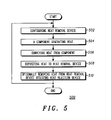
- FIG.5 is a flow chart 500 of an embodiment of the invention.
- heat removal device 108 is configured to fasten to mezzanine card 106 on electronics module 100, fasten to mezzanine card site 107 or is configured to occupy to the physical space envelope of mezzanine card 106.
- heat removal device 108 is configured to fasten to a CMC site or occupy CMC physical space envelope, and in a particularly preferred embodiment, heat removal device is configured to fasten to a PMC module site on electronics module 100.
- step 504 component 102 generates heat.
- heat 118 is conveyed from component 102 to heat removal device 108. In one embodiment, heat 118 is conveyed via heat conductor 112.
- heat 118 is deposited to heat removal device 108 mounted to electronics module 100. In an embodiment, heat 118 is received by heat removal device 108.
- an optional heat rejection device 122 removes heat from heat removal device 108. In one embodiment, heat rejection device 122 removes a portion of heat 126. In another embodiment, heat rejection device 122 removes all of heat 118. The method of the invention is repeated per the return arrow in FIG.5.
- the apparatus and method of the invention have the advantage of allowing additional heat removal means within the confines of an electronics enclosure that is directed specifically at one or more components.
- the invention also has the advantage of being configured to fasten within an existing mezzanine card physical space envelope.
- Yet another advantage of the invention is the ability to reduce the main cooling system in an electronics enclosure thereby increasing efficiency and reducing overall cooling costs.
Landscapes
- Cooling Or The Like Of Electrical Apparatus (AREA)
- Cooling Or The Like Of Semiconductors Or Solid State Devices (AREA)
- Electric Connection Of Electric Components To Printed Circuits (AREA)
- Encapsulation Of And Coatings For Semiconductor Or Solid State Devices (AREA)
Abstract
Description
Claims (10)
- In an electronics module (100), an apparatus for removing heat (118) from a component (102) located on a surface (104) of said electronics module, characterized by:a heat removal device (108) mounted to the electronics module, wherein the component is located a radial distance (110) from the heat removal device; anda heat conductor (112) having a first portion (115) coupled to the component and having a second portion (117) coupled to the heat removal device.
- The apparatus of claim 1, wherein the heat removal device is configured to fasten to a mezzanine card site on the electronics module.
- The apparatus of claim 1, wherein the heat removal device is configured to fasten to a mezzanine card on the electronics module.
- The apparatus of claim 1, wherein the heat removal device is configured to occupy a physical space envelope of a mezzanine card.
- An electronic device, characterized by:an electronics module (100) having a component (102) located on a surface (104) of said electronics module;a heat removal device (108) mounted to the electronics module, wherein the component is located a radial distance (110) from the heat removal device; anda heat conductor (112) having a first end coupled to the component and having a second end coupled to the heat removal device.
- The electronic device of claim 5, wherein the heat removal device is configured to fasten to a mezzanine card site on the electronics module.
- The electronic device of claim 5, wherein the heat removal device is configured to fasten to a mezzanine card on the electronics module.
- The electronic device of claim 5, wherein the heat removal device is configured to occupy a physical space envelope of a mezzanine card.
- In an electronics module (100), a method for removing heat from a component (102) located on a surface (104) of said electronics module, characterized by:the component generating heat;conveying the heat from the component by way of a heat conductor (112); anddepositing the heat to a heat removal device (108) mounted to the electronics module.
- The method of claim 9, further comprising configuring the heat removal device to fasten to a mezzanine card site on the electronics module.
Applications Claiming Priority (2)
| Application Number | Priority Date | Filing Date | Title |
|---|---|---|---|
| US09/960,017 US6538884B1 (en) | 2001-09-21 | 2001-09-21 | Method and apparatus for removing heat from a component |
| US960017 | 2001-09-21 |
Publications (3)
| Publication Number | Publication Date |
|---|---|
| EP1303174A2 true EP1303174A2 (en) | 2003-04-16 |
| EP1303174A3 EP1303174A3 (en) | 2005-01-12 |
| EP1303174B1 EP1303174B1 (en) | 2006-11-15 |
Family
ID=25502690
Family Applications (1)
| Application Number | Title | Priority Date | Filing Date |
|---|---|---|---|
| EP02019564A Expired - Lifetime EP1303174B1 (en) | 2001-09-21 | 2002-09-02 | Method and apparatus for removing heat from a component |
Country Status (6)
| Country | Link |
|---|---|
| US (1) | US6538884B1 (en) |
| EP (1) | EP1303174B1 (en) |
| JP (1) | JP4206435B2 (en) |
| AT (1) | ATE345664T1 (en) |
| CA (1) | CA2399898A1 (en) |
| DE (1) | DE60216033T2 (en) |
Families Citing this family (14)
| Publication number | Priority date | Publication date | Assignee | Title |
|---|---|---|---|---|
| JP3651677B2 (en) * | 2002-07-12 | 2005-05-25 | 株式会社東芝 | Heating element cooling device and electronic device |
| US6721182B1 (en) * | 2002-10-10 | 2004-04-13 | Harris Corporation | Circuit card module including mezzanine card heat sink and related methods |
| US6768642B2 (en) * | 2002-12-16 | 2004-07-27 | Lockheed Martin Corporation | VME circuit host card with triple mezzanine configuration |
| TW200537279A (en) * | 2004-05-13 | 2005-11-16 | Mitac Technology Corp | Heat sink module having heat conduction cover plate |
| US7369412B2 (en) * | 2006-05-02 | 2008-05-06 | Fu Zhun Precision Industry (Shen Zhen) Co., Ltd. | Heat dissipation device |
| US7391610B2 (en) | 2006-09-29 | 2008-06-24 | Rockwell Automation Technologies, Inc. | Thermal cooling of industrial electronic module by conductive structure |
| US7444209B2 (en) * | 2006-10-26 | 2008-10-28 | Honeywell International Inc. | Miniature cooling device |
| CN101315176A (en) * | 2007-06-01 | 2008-12-03 | 富士迈半导体精密工业(上海)有限公司 | Light source module with better heat dissipation efficiency |
| TW200910070A (en) * | 2007-08-28 | 2009-03-01 | Inventec Corp | Heat dissipation module |
| US20090323286A1 (en) * | 2008-06-13 | 2009-12-31 | Evga Corporation | Apparatus for removing heat from pc circuit board devices such as graphics cards and the like |
| TWI476575B (en) * | 2012-05-04 | 2015-03-11 | Inventec Corp | Electronic device and heat dissipation structure |
| US9013874B2 (en) * | 2012-09-12 | 2015-04-21 | Sk Hynix Memory Solutions Inc. | Heat dissipation device |
| US9497888B2 (en) * | 2013-02-27 | 2016-11-15 | International Business Machines Corporation | Thermal transfer structure(s) and attachment mechanism(s) facilitating cooling of electronics card(s) |
| JP6456891B2 (en) * | 2016-09-23 | 2019-01-23 | レノボ・シンガポール・プライベート・リミテッド | Electronics |
Family Cites Families (12)
| Publication number | Priority date | Publication date | Assignee | Title |
|---|---|---|---|---|
| EP0231456B1 (en) * | 1985-12-13 | 1991-06-26 | Ascom Hasler AG | Process and device for the transfer of waste heat by at least one element of an electrical assembly |
| US4931904A (en) | 1989-05-30 | 1990-06-05 | Motorola, Inc. | Localized circuit card cooling device |
| JPH0629683A (en) * | 1992-03-31 | 1994-02-04 | Furukawa Electric Co Ltd:The | Heat pipe type heat dissipation unit for electronic devices |
| US5343940A (en) * | 1992-10-29 | 1994-09-06 | Amigo Jean | Flexible heat transfer device |
| US5390734A (en) * | 1993-05-28 | 1995-02-21 | Lytron Incorporated | Heat sink |
| US5472043A (en) * | 1994-03-22 | 1995-12-05 | Aavid Laboratories, Inc. | Two-phase component cooler with radioactive initiator |
| US5613906A (en) | 1995-07-20 | 1997-03-25 | Elonex I.P. Holdings, Ltd. | Method and apparatus for waste heat removal from a computer enclosure |
| US5986887A (en) | 1998-10-28 | 1999-11-16 | Unisys Corporation | Stacked circuit board assembly adapted for heat dissipation |
| US6246582B1 (en) * | 1998-12-30 | 2001-06-12 | Honeywell Inc. | Interchangeable stiffening frame with extended width wedgelock for use in a circuit card module |
| TW448711B (en) * | 1999-07-22 | 2001-08-01 | Foxconn Prec Components Co Ltd | Heat dissipation device |
| US6407916B1 (en) * | 2000-06-12 | 2002-06-18 | Intel Corporation | Computer assembly for cooling high powered microprocessors |
| US6377459B1 (en) * | 2000-08-04 | 2002-04-23 | Sun Microsystems, Inc. | Chip cooling management |
-
2001
- 2001-09-21 US US09/960,017 patent/US6538884B1/en not_active Expired - Lifetime
-
2002
- 2002-08-27 CA CA002399898A patent/CA2399898A1/en not_active Abandoned
- 2002-09-02 DE DE60216033T patent/DE60216033T2/en not_active Expired - Lifetime
- 2002-09-02 AT AT02019564T patent/ATE345664T1/en not_active IP Right Cessation
- 2002-09-02 EP EP02019564A patent/EP1303174B1/en not_active Expired - Lifetime
- 2002-09-18 JP JP2002271249A patent/JP4206435B2/en not_active Expired - Fee Related
Also Published As
| Publication number | Publication date |
|---|---|
| JP2003179372A (en) | 2003-06-27 |
| US20030058616A1 (en) | 2003-03-27 |
| DE60216033D1 (en) | 2006-12-28 |
| EP1303174A3 (en) | 2005-01-12 |
| CA2399898A1 (en) | 2003-03-21 |
| US6538884B1 (en) | 2003-03-25 |
| EP1303174B1 (en) | 2006-11-15 |
| ATE345664T1 (en) | 2006-12-15 |
| JP4206435B2 (en) | 2009-01-14 |
| DE60216033T2 (en) | 2007-06-21 |
Similar Documents
| Publication | Publication Date | Title |
|---|---|---|
| US6538884B1 (en) | Method and apparatus for removing heat from a component | |
| US7715194B2 (en) | Methodology of cooling multiple heat sources in a personal computer through the use of multiple fluid-based heat exchanging loops coupled via modular bus-type heat exchangers | |
| US7405936B1 (en) | Hybrid cooling system for a multi-component electronics system | |
| US7012807B2 (en) | Thermal dissipation assembly and fabrication method for electronics drawer of a multiple-drawer electronics rack | |
| US7639498B2 (en) | Conductive heat transport cooling system and method for a multi-component electronics system | |
| US7120021B2 (en) | Liquid cooling system | |
| TWI308049B (en) | Systems to cool multiple electrical components | |
| US5933323A (en) | Electronic component lid that provides improved thermal dissipation | |
| US8474275B2 (en) | Modular absorption heat sink devices for passive cooling of servers and other electronics | |
| US6459576B1 (en) | Fan based heat exchanger | |
| EP3573438B1 (en) | Remote heat exchanger | |
| US20070291452A1 (en) | Heat Transfer Systems for Dissipating Thermal Loads From a Computer Rack | |
| CN112369131A (en) | Cooling electronic equipment in a data center | |
| US7339792B2 (en) | Graphics card apparatus with improved heat dissipating assemblies | |
| US8111516B2 (en) | Housing used as heat collector | |
| JPH10215094A (en) | Device for eliminating heat from pc card array | |
| US7321494B2 (en) | Graphics card apparatus with improved heat dissipating mechanisms | |
| KR20110027766A (en) | Dedicated air intake and air outlet for computer chassis chamber | |
| US6657859B1 (en) | Device bay heat exchanger for a portable computing device | |
| US20060203451A1 (en) | Heat dissipation apparatus with second degree curve shape heat pipe | |
| US20080218964A1 (en) | Desktop personal computer and thermal module thereof | |
| US20070297139A1 (en) | Heat sink with themoelectric module | |
| JP2002335091A (en) | Cooling device for exothermic electronic part | |
| US20050199377A1 (en) | Heat dissipation module with heat pipes | |
| WO2020162938A1 (en) | Photo-etched chassis cooling walls |
Legal Events
| Date | Code | Title | Description |
|---|---|---|---|
| PUAI | Public reference made under article 153(3) epc to a published international application that has entered the european phase |
Free format text: ORIGINAL CODE: 0009012 |
|
| AK | Designated contracting states |
Designated state(s): AT BE BG CH CY CZ DE DK EE ES FI FR GB GR IE IT LI LU MC NL PT SE SK TR |
|
| AX | Request for extension of the european patent |
Extension state: AL LT LV MK RO SI |
|
| PUAL | Search report despatched |
Free format text: ORIGINAL CODE: 0009013 |
|
| AK | Designated contracting states |
Kind code of ref document: A3 Designated state(s): AT BE BG CH CY CZ DE DK EE ES FI FR GB GR IE IT LI LU MC NL PT SE SK TR |
|
| AX | Request for extension of the european patent |
Extension state: AL LT LV MK RO SI |
|
| 17P | Request for examination filed |
Effective date: 20050315 |
|
| 17Q | First examination report despatched |
Effective date: 20050502 |
|
| AKX | Designation fees paid |
Designated state(s): AT BE BG CH CY CZ DE DK EE ES FI FR GB GR IE IT LI LU MC NL PT SE SK TR |
|
| GRAP | Despatch of communication of intention to grant a patent |
Free format text: ORIGINAL CODE: EPIDOSNIGR1 |
|
| GRAS | Grant fee paid |
Free format text: ORIGINAL CODE: EPIDOSNIGR3 |
|
| GRAA | (expected) grant |
Free format text: ORIGINAL CODE: 0009210 |
|
| AK | Designated contracting states |
Kind code of ref document: B1 Designated state(s): AT BE BG CH CY CZ DE DK EE ES FI FR GB GR IE IT LI LU MC NL PT SE SK TR |
|
| PG25 | Lapsed in a contracting state [announced via postgrant information from national office to epo] |
Ref country code: BE Free format text: LAPSE BECAUSE OF FAILURE TO SUBMIT A TRANSLATION OF THE DESCRIPTION OR TO PAY THE FEE WITHIN THE PRESCRIBED TIME-LIMIT Effective date: 20061115 Ref country code: IT Free format text: LAPSE BECAUSE OF FAILURE TO SUBMIT A TRANSLATION OF THE DESCRIPTION OR TO PAY THE FEE WITHIN THE PRESCRIBED TIME-LIMIT;WARNING: LAPSES OF ITALIAN PATENTS WITH EFFECTIVE DATE BEFORE 2007 MAY HAVE OCCURRED AT ANY TIME BEFORE 2007. THE CORRECT EFFECTIVE DATE MAY BE DIFFERENT FROM THE ONE RECORDED. Effective date: 20061115 Ref country code: NL Free format text: LAPSE BECAUSE OF FAILURE TO SUBMIT A TRANSLATION OF THE DESCRIPTION OR TO PAY THE FEE WITHIN THE PRESCRIBED TIME-LIMIT Effective date: 20061115 Ref country code: AT Free format text: LAPSE BECAUSE OF FAILURE TO SUBMIT A TRANSLATION OF THE DESCRIPTION OR TO PAY THE FEE WITHIN THE PRESCRIBED TIME-LIMIT Effective date: 20061115 Ref country code: LI Free format text: LAPSE BECAUSE OF FAILURE TO SUBMIT A TRANSLATION OF THE DESCRIPTION OR TO PAY THE FEE WITHIN THE PRESCRIBED TIME-LIMIT Effective date: 20061115 Ref country code: CH Free format text: LAPSE BECAUSE OF FAILURE TO SUBMIT A TRANSLATION OF THE DESCRIPTION OR TO PAY THE FEE WITHIN THE PRESCRIBED TIME-LIMIT Effective date: 20061115 Ref country code: FI Free format text: LAPSE BECAUSE OF FAILURE TO SUBMIT A TRANSLATION OF THE DESCRIPTION OR TO PAY THE FEE WITHIN THE PRESCRIBED TIME-LIMIT Effective date: 20061115 Ref country code: CZ Free format text: LAPSE BECAUSE OF FAILURE TO SUBMIT A TRANSLATION OF THE DESCRIPTION OR TO PAY THE FEE WITHIN THE PRESCRIBED TIME-LIMIT Effective date: 20061115 Ref country code: SK Free format text: LAPSE BECAUSE OF FAILURE TO SUBMIT A TRANSLATION OF THE DESCRIPTION OR TO PAY THE FEE WITHIN THE PRESCRIBED TIME-LIMIT Effective date: 20061115 |
|
| REG | Reference to a national code |
Ref country code: GB Ref legal event code: FG4D |
|
| REG | Reference to a national code |
Ref country code: CH Ref legal event code: EP |
|
| REF | Corresponds to: |
Ref document number: 60216033 Country of ref document: DE Date of ref document: 20061228 Kind code of ref document: P |
|
| REG | Reference to a national code |
Ref country code: IE Ref legal event code: FG4D |
|
| PG25 | Lapsed in a contracting state [announced via postgrant information from national office to epo] |
Ref country code: BG Free format text: LAPSE BECAUSE OF FAILURE TO SUBMIT A TRANSLATION OF THE DESCRIPTION OR TO PAY THE FEE WITHIN THE PRESCRIBED TIME-LIMIT Effective date: 20070215 Ref country code: SE Free format text: LAPSE BECAUSE OF FAILURE TO SUBMIT A TRANSLATION OF THE DESCRIPTION OR TO PAY THE FEE WITHIN THE PRESCRIBED TIME-LIMIT Effective date: 20070215 Ref country code: DK Free format text: LAPSE BECAUSE OF FAILURE TO SUBMIT A TRANSLATION OF THE DESCRIPTION OR TO PAY THE FEE WITHIN THE PRESCRIBED TIME-LIMIT Effective date: 20070215 |
|
| PG25 | Lapsed in a contracting state [announced via postgrant information from national office to epo] |
Ref country code: ES Free format text: LAPSE BECAUSE OF FAILURE TO SUBMIT A TRANSLATION OF THE DESCRIPTION OR TO PAY THE FEE WITHIN THE PRESCRIBED TIME-LIMIT Effective date: 20070226 |
|
| PG25 | Lapsed in a contracting state [announced via postgrant information from national office to epo] |
Ref country code: PT Free format text: LAPSE BECAUSE OF FAILURE TO SUBMIT A TRANSLATION OF THE DESCRIPTION OR TO PAY THE FEE WITHIN THE PRESCRIBED TIME-LIMIT Effective date: 20070416 |
|
| NLV1 | Nl: lapsed or annulled due to failure to fulfill the requirements of art. 29p and 29m of the patents act | ||
| ET | Fr: translation filed | ||
| REG | Reference to a national code |
Ref country code: CH Ref legal event code: PL |
|
| PLBE | No opposition filed within time limit |
Free format text: ORIGINAL CODE: 0009261 |
|
| STAA | Information on the status of an ep patent application or granted ep patent |
Free format text: STATUS: NO OPPOSITION FILED WITHIN TIME LIMIT |
|
| 26N | No opposition filed |
Effective date: 20070817 |
|
| PG25 | Lapsed in a contracting state [announced via postgrant information from national office to epo] |
Ref country code: MC Free format text: LAPSE BECAUSE OF NON-PAYMENT OF DUE FEES Effective date: 20070930 Ref country code: GR Free format text: LAPSE BECAUSE OF FAILURE TO SUBMIT A TRANSLATION OF THE DESCRIPTION OR TO PAY THE FEE WITHIN THE PRESCRIBED TIME-LIMIT Effective date: 20070216 |
|
| GBPC | Gb: european patent ceased through non-payment of renewal fee |
Effective date: 20070902 |
|
| PG25 | Lapsed in a contracting state [announced via postgrant information from national office to epo] |
Ref country code: IE Free format text: LAPSE BECAUSE OF NON-PAYMENT OF DUE FEES Effective date: 20070903 |
|
| PG25 | Lapsed in a contracting state [announced via postgrant information from national office to epo] |
Ref country code: GB Free format text: LAPSE BECAUSE OF NON-PAYMENT OF DUE FEES Effective date: 20070902 |
|
| PG25 | Lapsed in a contracting state [announced via postgrant information from national office to epo] |
Ref country code: EE Free format text: LAPSE BECAUSE OF FAILURE TO SUBMIT A TRANSLATION OF THE DESCRIPTION OR TO PAY THE FEE WITHIN THE PRESCRIBED TIME-LIMIT Effective date: 20061115 |
|
| PG25 | Lapsed in a contracting state [announced via postgrant information from national office to epo] |
Ref country code: LU Free format text: LAPSE BECAUSE OF NON-PAYMENT OF DUE FEES Effective date: 20070902 Ref country code: CY Free format text: LAPSE BECAUSE OF FAILURE TO SUBMIT A TRANSLATION OF THE DESCRIPTION OR TO PAY THE FEE WITHIN THE PRESCRIBED TIME-LIMIT Effective date: 20061115 |
|
| PG25 | Lapsed in a contracting state [announced via postgrant information from national office to epo] |
Ref country code: TR Free format text: LAPSE BECAUSE OF FAILURE TO SUBMIT A TRANSLATION OF THE DESCRIPTION OR TO PAY THE FEE WITHIN THE PRESCRIBED TIME-LIMIT Effective date: 20061115 |
|
| PGFP | Annual fee paid to national office [announced via postgrant information from national office to epo] |
Ref country code: DE Payment date: 20090929 Year of fee payment: 8 |
|
| REG | Reference to a national code |
Ref country code: FR Ref legal event code: ST Effective date: 20110531 |
|
| REG | Reference to a national code |
Ref country code: DE Ref legal event code: R119 Ref document number: 60216033 Country of ref document: DE Effective date: 20110401 |
|
| PG25 | Lapsed in a contracting state [announced via postgrant information from national office to epo] |
Ref country code: DE Free format text: LAPSE BECAUSE OF NON-PAYMENT OF DUE FEES Effective date: 20110401 Ref country code: FR Free format text: LAPSE BECAUSE OF NON-PAYMENT OF DUE FEES Effective date: 20100930 |
|
| PGFP | Annual fee paid to national office [announced via postgrant information from national office to epo] |
Ref country code: FR Payment date: 20091006 Year of fee payment: 8 |