EP1303142B1 - Filtering circuit for video data in the frequency domain - Google Patents
Filtering circuit for video data in the frequency domain Download PDFInfo
- Publication number
- EP1303142B1 EP1303142B1 EP02078817A EP02078817A EP1303142B1 EP 1303142 B1 EP1303142 B1 EP 1303142B1 EP 02078817 A EP02078817 A EP 02078817A EP 02078817 A EP02078817 A EP 02078817A EP 1303142 B1 EP1303142 B1 EP 1303142B1
- Authority
- EP
- European Patent Office
- Prior art keywords
- data
- odd
- transformed data
- deliver
- transformation
- Prior art date
- Legal status (The legal status is an assumption and is not a legal conclusion. Google has not performed a legal analysis and makes no representation as to the accuracy of the status listed.)
- Expired - Lifetime
Links
Images
Classifications
-
- H—ELECTRICITY
- H04—ELECTRIC COMMUNICATION TECHNIQUE
- H04N—PICTORIAL COMMUNICATION, e.g. TELEVISION
- H04N19/00—Methods or arrangements for coding, decoding, compressing or decompressing digital video signals
- H04N19/42—Methods or arrangements for coding, decoding, compressing or decompressing digital video signals characterised by implementation details or hardware specially adapted for video compression or decompression, e.g. dedicated software implementation
-
- H—ELECTRICITY
- H04—ELECTRIC COMMUNICATION TECHNIQUE
- H04N—PICTORIAL COMMUNICATION, e.g. TELEVISION
- H04N19/00—Methods or arrangements for coding, decoding, compressing or decompressing digital video signals
- H04N19/60—Methods or arrangements for coding, decoding, compressing or decompressing digital video signals using transform coding
- H04N19/61—Methods or arrangements for coding, decoding, compressing or decompressing digital video signals using transform coding in combination with predictive coding
-
- H—ELECTRICITY
- H04—ELECTRIC COMMUNICATION TECHNIQUE
- H04N—PICTORIAL COMMUNICATION, e.g. TELEVISION
- H04N19/00—Methods or arrangements for coding, decoding, compressing or decompressing digital video signals
- H04N19/80—Details of filtering operations specially adapted for video compression, e.g. for pixel interpolation
-
- H—ELECTRICITY
- H04—ELECTRIC COMMUNICATION TECHNIQUE
- H04N—PICTORIAL COMMUNICATION, e.g. TELEVISION
- H04N19/00—Methods or arrangements for coding, decoding, compressing or decompressing digital video signals
- H04N19/85—Methods or arrangements for coding, decoding, compressing or decompressing digital video signals using pre-processing or post-processing specially adapted for video compression
- H04N19/86—Methods or arrangements for coding, decoding, compressing or decompressing digital video signals using pre-processing or post-processing specially adapted for video compression involving reduction of coding artifacts, e.g. of blockiness
Definitions
- the present invention relates to a filter circuit of an original data set able to implement in series the steps of discrete transformation, correction of odd transformed data and inverse discrete transformation.
- the MPEG standard (of the English ⁇ Moving Pictures Expert Group ') for example, is necessary to mitigate the visual artifacts caused by said block coding technique.
- Block artifact Video compression algorithms using block coding techniques sometimes lead to a degradation of the quality of the coded and decoded images.
- a filter circuit of an image data set comprising a first processing stage corresponding to a first sub-step of a discrete transformation and able to process the original data and to output odd intermediate transformed data, and a first set of processing stages corresponding to a set of sub steps of the discrete transformation, able to process the odd intermediate transformed data and to deliver odd transformed data; a correction unit adapted to process the odd transformed data and to output odd corrected transform data; and a second set of processing stages corresponding to a set of sub-steps of an inverse discrete transformation, able to process the odd corrected transform data and to output intermediate filtered data, and a last processing stage corresponding to a last sub-stage. step of the inverse discrete transformation and able to process the intermediate filtered data.
- the present invention aims to provide a data filtering circuit for simply implementing the data filtering method of the prior art.
- Direct discrete cosine (DCT2) and inverse (IDCT2) transforms process the 2N concatenated data X0 to X7 using Lee's algorithm.
- the black dots represent additions or subtractions, a horizontal line in dotted lines preceding a black dot corresponding to a data item to be subtracted.
- the white dots correspond to multiplications.
- the multiplications and divisions by a power of 2 have not been represented in the diagram of FIG. 3 because they have little influence on the complexity of the implementation.
- the implementation of the correction (ZER) by zeroing the odd transformed data resulting from the global discrete transformation whose frequency is greater than the maximum predicted frequency is carried out with 4 logic circuits performing the 'AND' function between the transformed data. and outputs of a calculation circuit (PRED) of a maximum predicted frequency.
- PRED calculation circuit
- the data filtering circuit resulting from this conventional implementation would therefore lead to a complex solution comprising a DCT and an IDCT for each point of a block border.
- This solution would also have the disadvantage of being both expensive and power intensive.
- the present invention relates to a data filtering circuit for correcting block artifacts in the frequency domain. It is valid for any circuit capable of implementing in series the steps of discrete transformation of original data, correction of odd transformed data and inverse discrete transformation.
- the discrete transformation is a discrete cosine transformation.
- the present invention takes into consideration the fact that the direct and inverse calculation paths of the DCT discrete cosine transform and the Discrete Inverse IDCT cosine transform are identical and traversed in opposite directions. Thus, if the processing of a data item is not affected by the correction, the stages of Processing DCT and IDCT inverse discrete cosine transformations corresponding to this data can be suppressed to a certain extent.
- the present invention takes advantage of the fact that, for a number of data to be processed equal to a power of 2, the data paths of the odd and even transformed data are completely dissociated, as shown in FIG. 3, with the exception of a first processing stage (ST1) of the discrete cosine transformation DCT and a last processing stage (ST8) of the inverse discrete cosine transformation IDCT.
- ST1 first processing stage
- ST8 last processing stage
- the correction affecting only the odd transformed data, the processing stages located between the first and the last stage and processing the even data can be deleted.
- a correction unit (ZER) of the odd transformed data is performed with 4 logic circuits performing the 'AND' function.
- the inputs of the logic circuits are on the one hand Y1, Y3, Y5 and Y7, and on the other hand an output value opposite the value provided by a PRED calculation circuit of a predicted maximum frequency. This output value is 1 if the odd transformed data YZ is of higher frequency than the maximum predicted frequency and 0 otherwise YNZ.
- the odd corrected transformed data resulting from the logical'ET 'are therefore either odd transformed data YZ to be zeroed or 0.
- the correction unit (ZER) cancels the odd transformed data YNZ other than those YZ before be set to zero.
- the odd data with h included here between 0 and 4, whose frequency is greater than the maximum predicted frequency, are not corrected while the other odd data are set to zero in order to be processed by the inverse discrete transformation. (IDCT2) so as to generate the differential data DX.
- IDCT2 inverse discrete transformation
- the last stage then acts as a differential stage, able to subtract the intermediate filtered data from the seventh floor to a first half of the data. of origin (X0-X3) and to add said intermediate filtered data to a second half of the original data (X4-X7).
- the number of operations is equal to 48, ie 36 additions and 12 multiplications, ie 32 operations less than the conventional embodiment of FIG. 3.
- the circuit can be simplified in some special cases. For example, when a minority of odd transformed data must be set to zero, it is possible to advantageously replace the processing path of the second half of data (X4-X7 to XF4-XF7) of FIG. 4 by a simpler processing path.
- the first stage (ST1) and the last stage remain unchanged with respect to the circuit of FIG. 4.
- the second stage (ST2) of the data filtering circuit now comprises 4 multipliers, each intermediate transformed data Odd being multiplied by a multiplicative coefficient.
- the third stage (ST3) comprises two adders respectively carrying out the sum, on the one hand data from lines 4 and 5 of the second stage, and secondly data from lines 6 and 7 of the second stage.
- the fourth stage (ST4) adds the results of these two adders, thus forming the odd transformed data YZ7.
- the fifth floor (ST5) does nothing.
- the sixth (ST6) stage duplicates the odd transformed data YZ7 for lines 4 to 7 and the seventh stage (ST7) multiplies each duplicate data by a multiplicative coefficient.
- the number of operations is only 25, that is 17 additions and 8 multiplications.
- a majority of odd transformed data must be set to zero.
- the first stage (ST1) remains unchanged with respect to the circuit of FIG. 4.
- the second stage (ST2) of the data filtering circuit according to this embodiment now comprises 4 multipliers, each odd intermediate transformed data being multiplied by a multiplicative coefficient.
- the third floor (ST3) has 2 adders respectively carrying out the sum, on the one hand data from lines 4 and 5 of the second floor, and secondly data from lines 6 and 7 of the second floor.
- the fourth stage (ST4) performs the addition of the results of these two adders, thus forming the odd transformed data YNZ1.
- the fifth stage (ST5) duplicates the opposite of the transformed data YNZ1 for lines 4 to 7.
- the sixth stage (ST6) multiplies each duplicate data by a multiplicative coefficient.
- the seventh stage (ST7) has 4 adders each performing a sum of a multiplied data and an odd intermediate transformed data of the same line.
- the eighth and last stage (ST8) has 8 adders, 4 adders performing the same subtractions as in FIG. 4 for lines 0 to 3, and 4 adders each subtracting an intermediate filtered data of line j from an original data X (j) of the same line for lines 4 to 7.
- the number of operations is equal to 29, that is 21 additions and 8 multiplications.
- Circuits such as those described in FIGS. 4, 5, 6 may be implemented in a data filtering device, a control circuit for selecting the adapted circuit from this set of circuits as a function of the number h of odd transformed data to be set to zero.
- the filtering circuit according to the invention can be integrated either as an output unit of a video decoder or as an input unit of a television receiver, in order to process decoded digital data.
- the present invention has been realized as part of the implementation of the data filtering method of the state of the art.
- the simplifications made to the filtering architecture also make it possible to improve said data filtering method.
- An instruction set contained in a programming memory may cause the circuit to perform the various steps previously described.
- the instruction set can also be loaded into the programming memory by reading a data medium such as, for example, a disk that contains the instruction set. Reading can also be done via a network of communication like, for example, the internet network. In this case, a service provider will make the instruction set available to interested parties.
Abstract
Description
La présente invention concerne un circuit de filtrage d'un ensemble de données d'origine apte à mettre en oeuvre en séries les étapes de transformation discrète, de correction de données transformées impaires et de transformation discrète Inverse.The present invention relates to a filter circuit of an original data set able to implement in series the steps of discrete transformation, correction of odd transformed data and inverse discrete transformation.
Elle concerne également un procédé de filtrage d'un ensemble de données d'origine comprenant les étapes citées précédemment. Elle concerne enfin un produit programme d'ordinateur' apte à mettre en oeuvre ledit procédé de filtrage de données.It also relates to a filtering method of a set of original data comprising the steps mentioned above. Finally, it relates to a computer program product capable of implementing said data filtering method.
Elle trouve notamment son application dans les décodeurs vidéo et dans les récepteurs de télévision, où la correction d'images numériques précédemment codées puis décodées selon une technique de codage par blocs, la norme MPEG (de l'anglais `Moving Pictures Expert Group') par exemple, est nécessaire pour atténuer les artefacts visuels causés par ladite technique de codage par blocs.It finds particular application in video decoders and in television receivers, where the correction of digital images previously coded and then decoded according to a block coding technique, the MPEG standard (of the English `Moving Pictures Expert Group ') for example, is necessary to mitigate the visual artifacts caused by said block coding technique.
Les algorithmes de compression vidéo utilisant des techniques de codage par blocs conduisent parfois à une dégradation de la qualité des images codées puis décodées. Un des artefacts visuels le plus couramment observé avec ces techniques de codage est appelé artefact de bloc.Video compression algorithms using block coding techniques sometimes lead to a degradation of the quality of the coded and decoded images. One of the most commonly observed visual artifacts with these coding techniques is called block artifact.
L'article H. Paek, E.-C. Kim, S.-U. Lee, "On the POCS-Based Postprocessing Technique to Reduce the Blocking Artifacts in Transform Coded Images", IEEE Transactions on Circuits and Systems for Video Technology, vol. 8, no. 3, June 1998, pages 358-367, décrit un circuit de filtrage d'un ensemble de données d'image comprenant
un premier étage de traitement correspondant à une première sous-étape d'une transformation discrète et apte à traiter les données d'origine et à délivrer des données transformées intermédiaires impaires, et un premier ensemble d'étages de traitement correspondant à un ensemble de sous-étapes de la transformation discrète, apte à traiter les données transformées intermédiaires impaires et à délivrer des données transformées impaires;
une unité de correction apte à traiter les données transformées impaires et à délivrer des données transformées corrigées impaires; et
un second ensemble d'étages de traitement correspondant à un ensemble de sous-étapes d'une transformation discrète inverse, apte à traiter les données transformées corrigées impaires et à délivrer des données filtrées intermédiaires, et un dernier étage de traitement correspondant à une dernière sous-étape de la transformation discrète inverse et apte à traiter les données filtrées intermédiaires.Article H. Paek, E.-C. Kim, S.-U. Lee, "On the POCS-Based Postprocessing Technique to Reduce the Blocking Artifacts in Transformed Coded Images," IEEE Transactions on Circuits and Systems for Video Technology, Vol. 8, no. 3, June 1998, pages 358-367, discloses a filter circuit of an image data set comprising
a first processing stage corresponding to a first sub-step of a discrete transformation and able to process the original data and to output odd intermediate transformed data, and a first set of processing stages corresponding to a set of sub steps of the discrete transformation, able to process the odd intermediate transformed data and to deliver odd transformed data;
a correction unit adapted to process the odd transformed data and to output odd corrected transform data; and
a second set of processing stages corresponding to a set of sub-steps of an inverse discrete transformation, able to process the odd corrected transform data and to output intermediate filtered data, and a last processing stage corresponding to a last sub-stage. step of the inverse discrete transformation and able to process the intermediate filtered data.
L'article K. Y. Kwak, R. A. Haddad, "Projection-Based Eigenvector Decomposition for Reduction of Blocking Artifacts of DCT Coded Image", Proceedings of the International Conference on Image Processing. (ICIP), Washington, Octobre 23 - 26, 1995, Los Alamitos, IEEE Comp. Soc. Press, USA, vol. 3, pages 527-530, décrit un circuit de filtrage d'un ensemble de données d'image, où les paires des transformations cosinus discrètes directes et inverses consécutives dans le circuit d'itération sont supprimées.K. Y. Kwak, R. A. Haddad, "Projection-Based Eigenvector Decomposition for Reduction of Blocking Artifacts of DCT Coded Image," Proceedings of the International Conference on Image Processing. (ICIP), Washington, October 23 - 26, 1995, Los Alamitos, IEEE Comp. Soc. Press, USA, vol. 3, pages 527-530, discloses a filter circuit of a set of image data, wherein the pairs of consecutive direct and inverse discrete cosine transformations in the iteration circuit are suppressed.
L'article intitulé "A projection-based post-processing technique to reduce blocking artifacts using a priori information on DCT coefficients of adjacent blocks", et publié par Hoon Paek et Sang-Uk Lee, dans "Proceedings of 3rd IEEE International Conference on Image Processing, vol 2, Lausanne, Switzerland, 16-19 Sept 1996, p 53-56" décrit une méthode de filtrage de données contenues dans une image numérique. Cette méthode de filtrage de données a pour but de corriger, dans le domaine fréquentiel, les coefficients qui correspondent à ces artefacts de blocs.The article "A projection-based post-processing technique to reduce blocking artifacts using a priori information on DCT coefficients of adjacent blocks", and published by Hoon Paek and Sang-Uk Lee, in "Proceedings of the 3rd IEEE International Conference on Image" Processing,
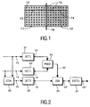
Elle est basée sur le principe suivant. Soient deux segments adjacents u (13) et v (14), tels qu'illustrés à la Fig. 1, appartenant respectivement à deux blocs (11,12) de pixels (10), et disposés de part et d'autre d'une frontière de blocs (16). Si un artefact de blocs est présent entre les segments u et v, le segment w (15) correspondant à la concaténation des premier et second segments inclut des hautes fréquences spatiales qui vont au-delà de celles des segments u et v.It is based on the following principle. Let two adjacent segments u (13) and v (14), as illustrated in FIG. 1, respectively belonging to two blocks (11,12) of pixels (10), and arranged on either side of a block boundary (16). If a block artifact is present between the u and v segments, the w (15) segment corresponding to the concatenation of the first and second segments includes high spatial frequencies that go beyond those of the u and v segments.
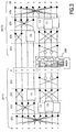
Afin de trouver et de supprimer les fréquences associées aux artefacts de blocs, la méthode de filtrage de données de l'état de la technique antérieure, illustrée à la Fig. 2, comprend les étapes suivantes de :
- calcul d'une première transformation DCT1 (21) en cosinus discrète du segment u de N pixels avec N = 8 dans l'exemple suivant : U = DCT[u] = {U(0), U(1), ..., U(N-1)}, avec

- calcul d'une seconde transformation DCT1 (22) en cosinus discrète du segment v de N pixels, adjacent au segment u : V=DCT(v)={V(0), V(1), ..., V(N-1)}, soit

- calcul d'une transformation DCT2 (23) en cosinus discrète globale du segment w de 2N soit 16 pixels correspondant à la concaténation CON (20) des segments u et v :W=DCT(w)={W(0), W(1), ..., W(2N-1)}, soit

- calcul PRED (24) d'une fréquence maximale prédite kwpred (25) en fonction des fréquences maximales kumax et kvmax de U (13') et V (14'), comme suit :

avec
kumax = max( k∈{0,...,N-1} / U(k)≠ 0),
kvmax = max( ke{0,...,N-1} / V(k) ≠ 0), et
max est la fonction qui donne le maximum de k parmi un ensemble de valeurs déterminées ; - correction ZER (26) par mise à zéro des données transformées impaires W (15') issues de la transformation discrète globale dont la fréquence est supérieure à la fréquence maximale prédite, fournissant des données corrigées (15").
- calcul d'une transformation en cosinus discrète inverse IDCT2 (27) des données corrigées, fournissant des données filtrées (15"') qui sont ensuite destinées à être affichées à l'écran.
- calculating a first discrete cosine transformation DCT1 (21) of the segment u of N pixels with N = 8 in the following example: U = DCT [u] = {U (0), U (1), ... , U (N-1)}, with
- calculating a second discrete cosine transformation DCT1 (22) of the v-segment of N pixels, adjacent to the u-segment: V = DCT (v) = {V (0), V (1), ..., V (N) -1)}, either
- calculating an overall discrete cosine DCT2 (23) transformation of the w segment of 2N,
ie 16 pixels corresponding to the concatenation CON (20) of the u and v segments: W = DCT (w) = {W (0), W ( 1), ..., W (2N-1)}, either - PRED calculation (24) of a maximum predicted frequency kwpred (25) as a function of the maximum frequencies kumax and kvmax of U (13 ') and V (14'), as follows:
with
kumax = max (k∈ {0, ..., N-1} / U (k) ≠ 0),
kvmax = max (ke {0, ..., N-1} / V (k) ≠ 0), and
max is the function that gives the maximum of k among a set of determined values; - ZER correction (26) by zeroing the odd transformed data W (15 ') from the overall discrete transformation whose frequency is greater than the maximum predicted frequency, providing corrected data (15 ").
- calculating an inverse discrete cosine transformation IDCT2 (27) of the corrected data, providing filtered data (15 "') which is then intended to be displayed on the screen.
La présente invention a pour but de proposer un circuit de filtrage de données permettant de mettre en oeuvre simplement la méthode de filtrage de données de l'état de la technique antérieure.The present invention aims to provide a data filtering circuit for simply implementing the data filtering method of the prior art.
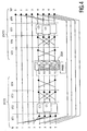
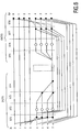
En effet, la mise en oeuvre d'une telle méthode peut s'avérer complexe en nombre d'opérations, notamment en ce qui concerne la séquence comprenant la transformation en cosinus discrète globale, suivie de la correction des données transformées impaires et de la transformation en cosinus discrète inverse. La Fig. 3 illustre ce que serait une implémentation conventionnelle d'une telle séquence dans le cas où 2N = 8. Les transformations en cosinus discrète directe (DCT2) et inverse (IDCT2) traitent les 2N données concaténées X0 à X7 en utilisant l'algorithme de Lee. Les points noirs représentent des additions ou des soustractions, une ligne horizontale en pointillés précédant un point noir correspondant à une donnée à soustraire. Les points blancs correspondent à des multiplications. Les multiplications et les divisions par une puissance de 2 n'ont pas été représentées sur le schéma de la Fig. 3 car elles ont peu d'influence sur la complexité de l'implémentation.Indeed, the implementation of such a method can be complex in number of operations, in particular with regard to the sequence comprising the global discrete cosine transformation, followed by the correction of the odd transformed data and the transformation. in inverse discrete cosine. Fig. 3 illustrates what would be a conventional implementation of such a sequence in the case where 2N = 8. Direct discrete cosine (DCT2) and inverse (IDCT2) transforms process the 2N concatenated data X0 to X7 using Lee's algorithm. The black dots represent additions or subtractions, a horizontal line in dotted lines preceding a black dot corresponding to a data item to be subtracted. The white dots correspond to multiplications. The multiplications and divisions by a power of 2 have not been represented in the diagram of FIG. 3 because they have little influence on the complexity of the implementation.
L'implémentation de la transformation en cosinus discrète globale (DCT2) comprend 4 étages successifs séparés sur la Fig. 3 par des lignes verticales en pointillés, à savoir :
- un premier étage (ST1) comportant 8 additionneurs (effectuant des additions ou des soustractions) des données concaténées,
- un deuxième étage (ST2) comportant 4 additionneurs et de 2 unités de rotation (C1,C3) de données, un unité de rotation comprenant 3 additionneurs et 3 multiplieurs selon un principe connu de l'homme du métier,
- un troisième étage (ST3) comportant 6 additionneurs et une unité de rotation (C6), et
- un quatrième étage (ST4) comportant 2 additionneurs et 2 multiplieurs, et fournissant les données transformées impaires Y1, Y3, Y5 et Y7, les données transformés paires Y0, Y2, Y4 et Y6 résultant des données traitées par le troisième étage et non traitées dans le quatrième étage.
- a first stage (ST1) comprising 8 adders (performing additions or subtractions) of the concatenated data,
- a second stage (ST2) having 4 adders and 2 data rotation units (C1, C3), a rotation unit comprising 3 adders and 3 multipliers according to a principle known to those skilled in the art,
- a third stage (ST3) having 6 adders and a rotation unit (C6), and
- a fourth stage (ST4) having 2 adders and 2 multipliers, and providing the odd transformed data Y1, Y3, Y5 and Y7, the pair transformed data Y0, Y2, Y4 and Y6 resulting from the third stage processed data and untreated in the fourth floor.
L'implémentation de la correction (ZER) par mise à zéro des données transformées impaires issues de la transformation discrète globale dont la fréquence est supérieure à la fréquence maximale prédite, est réalisée avec 4 circuits logiques réalisant la fonction 'ET' entre les données transformées impaires et des sorties d'un circuit de calcul (PRED) d'une fréquence maximale prédite.The implementation of the correction (ZER) by zeroing the odd transformed data resulting from the global discrete transformation whose frequency is greater than the maximum predicted frequency, is carried out with 4 logic circuits performing the 'AND' function between the transformed data. and outputs of a calculation circuit (PRED) of a maximum predicted frequency.
L implémentation de la transformation en cosinus discrète inverse (IDCT2) comprend 4 étages successifs :
- un cinquième étage (ST5) comportant 2 additionneurs et 2 multiplieurs aptes à traiter les données transformées impaires corrigées,
- un sixième étage (ST6) comportant 6 additionneurs et une unité rotation (C6),
- un septième étage (ST7) comportant 4 additionneurs et de 2 unités de rotation (C1,C3), et
- un huitième et dernier étage (ST8) comportant 8 additionneurs, et fournissant les données filtrées (XF0 à XF7).
- a fifth stage (ST5) comprising 2 adders and 2 multipliers able to process the corrected odd transformed data,
- a sixth stage (ST6) having 6 adders and a rotation unit (C6),
- a seventh stage (ST7) having 4 adders and 2 rotation units (C1, C3), and
- an eighth and last stage (ST8) having 8 adders, and providing the filtered data (XF0 to XF7).
Le circuit de filtrage de données résultant de cette implémentation conventionnelle conduirait donc à une solution complexe comprenant une DCT et une IDCT pour chaque point d'une frontière de bloc. Cette solution présenterait en outre l'inconvénient d'être à la fois coûteuse et fortement consommatrice de puissance.The data filtering circuit resulting from this conventional implementation would therefore lead to a complex solution comprising a DCT and an IDCT for each point of a block border. This solution would also have the disadvantage of being both expensive and power intensive.
Afin de remédier à cet inconvénient, le circuit de filtrage de données selon un mode de réalisation préféré de l'invention est remarquable en ce qu'il comprend :
- un premier étage de traitement correspondant à une première sous-étape d'une transformation discrète et apte à traiter les données d'origine et à délivrer des données transformées intermédiaires Impaires, et un premier ensemble d'étages de traitement correspondant à un ensemble de sous-étapes de la transformation discrète, apte à traiter les données transformées intermédiaires impaires et à délivrer des données transformées impaires,
- une unité de correction apte à annuler les données transformées Impaires autres que celles devant être mises à zéro, et à délivrer des données transformées corrigées impaires, et
- un second ensemble d'étages de traitement correspondant à un ensemble de sous-étapes d'une transformation discrète inverse apte à traiter les données transformées corrigées impaires et à délivrer des données filtrées intermédiaires, et un dernier étage de traitement correspondant à une dernière sous-étape de la transformation discrète inverse et apte à traiter les données d'origine et les données filtrées intermédiaires.
- a first processing stage corresponding to a first sub-step of a discrete transformation and able to process the original data and to output odd intermediate transformed data, and a first set of processing stages corresponding to a set of sub -steps of the discrete transformation, able to process the odd intermediate transformed data and to deliver odd transformed data,
- a correction unit adapted to cancel the odd transformed data other than those to be reset, and to output odd corrected transformed data, and
- a second set of processing stages corresponding to a set of sub-steps of an inverse discrete transformation adapted to process the odd corrected transformed data and to output intermediate filtered data, and a last processing stage corresponding to a last sub-step; stage of the inverse discrete transformation and able to process the original data and the intermediate filtered data.
Avec de tels circuits de filtrage de données, le nombre de multiplieurs et d'additionneurs est réduit, puisqu'au moins 28 opérations de multiplication ou d'addition sont supprimées selon le mode de réalisation préféré, et au moins 24 opérations selon le mode de réalisation avantageux. L'implémentation de la séquence de traitement de données comprenant en séries la transformation discrète, la correction des données transformées impaires et la transformation discrète inverse se trouve ainsi simplifiée, résultant en un circuit de filtrage à la fois moins coûteux et à plus faible consommation.With such data filtering circuits, the number of multipliers and adders is reduced, since at least 28 multiplication or addition operations are deleted according to the preferred embodiment, and at least 24 operations according to the advantageous embodiment. The implementation of the data processing sequence comprising in series the discrete transformation, the correction of the odd transformed data and the inverse discrete transformation is thus simplified, resulting in a filter circuit that is both less expensive and has lower consumption.
Ces aspects de l'invention ainsi que d'autres aspects plus détaillés apparaîtront plus clairement grâce à la description suivante de plusieurs modes de réalisation de l'invention, donnés à titre d'exemples non limitatifs et en regard des dessins annexés parmi lesquels :
- la Fig. 1 illustre deux segments adjacents disposés de part et d'autre d'une frontière de blocs,
- la Fig. 2 représente la méthode de traitement de données de l'état de la technique antérieure,
- la Fig. 3 Illustre un circuit mettant en oeuvre de façon conventionnelle la méthode de traitement de données de l'état de la technique antérieure,
- la Fig. 4 représente un mode de réalisation préféré du circuit de filtrage de données selon l'invention,
- la Fig. 5 représente une première variante du mode de réalisation préféré du circuit de filtrage de données selon l'invention,
- la Fig. 6 représente une seconde variante du mode de réalisation préféré du circuit de filtrage de données selon l'invention,
- FIG. 1 illustrates two adjacent segments arranged on either side of a block boundary,
- FIG. 2 represents the data processing method of the state of the art,
- FIG. Illustrates a circuit conventionally implementing the data processing method of the state of the prior art,
- FIG. 4 represents a preferred embodiment of the data filtering circuit according to the invention,
- FIG. 5 represents a first variant of the preferred embodiment of the data filtering circuit according to the invention,
- FIG. 6 represents a second variant of the preferred embodiment of the data filtering circuit according to the invention,
La présente invention concerne un circuit de filtrage de données pour corriger les artéfacts de blocs dans le domaine fréquentiel. Elle est valable pour tout circuit apte à mettre en oeuvre en séries les étapes de transformation discrète de données d'origine, de correction de données transformées impaires et de transformation discrète inverse.The present invention relates to a data filtering circuit for correcting block artifacts in the frequency domain. It is valid for any circuit capable of implementing in series the steps of discrete transformation of original data, correction of odd transformed data and inverse discrete transformation.
Dans la description qui suit, la transformation discrète est une transformation en cosinus discrète. La présente invention prend en considération le fait que les chemins de calcul direct et Inverse de la transformation en cosinus discrète DCT et de la transformation en cosinus discrète Inverse IDCT sont identiques et traversés dans des directions opposées. Ainsi, si le traitement d'une donnée n'est pas affecté par la correction, les étages de traitement des transformations en cosinus discrète directe DCT et inverse IDCT correspondant à cette donnée peuvent être supprimés dans une certaine mesure.In the following description, the discrete transformation is a discrete cosine transformation. The present invention takes into consideration the fact that the direct and inverse calculation paths of the DCT discrete cosine transform and the Discrete Inverse IDCT cosine transform are identical and traversed in opposite directions. Thus, if the processing of a data item is not affected by the correction, the stages of Processing DCT and IDCT inverse discrete cosine transformations corresponding to this data can be suppressed to a certain extent.
De plus, la présente invention tire notamment profit du fait que, pour un nombre de données à traiter égal à une puissance de 2, les chemins de données des données transformées paires et impaires sont complètement dissociés, comme le montre la Fig. 3, à l'exception d'un premier étage de traitement (ST1) de la transformation en cosinus discrète DCT et d'un dernier étage de traitement (ST8) de la transformation en cosinus discrète inverse IDCT. La correction affectant uniquement les données transformées impaires, les étages de traitement situés entre la premier et la dernier étage et traitant les données paires peuvent être supprimés.In addition, the present invention takes advantage of the fact that, for a number of data to be processed equal to a power of 2, the data paths of the odd and even transformed data are completely dissociated, as shown in FIG. 3, with the exception of a first processing stage (ST1) of the discrete cosine transformation DCT and a last processing stage (ST8) of the inverse discrete cosine transformation IDCT. The correction affecting only the odd transformed data, the processing stages located between the first and the last stage and processing the even data can be deleted.
Il apparaîtra ainsi à l'homme du métier que la présente invention s'applique à toute transformation discrète linéaire présentant les caractéristiques énoncées ci-dessus.It will thus be apparent to those skilled in the art that the present invention applies to any discrete linear transformation having the characteristics set forth above.
Dans le mode de réalisation préféré, le circuit de filtrage de données tire profit de la linéarité des transformations en cosinus discrète directe DCT et inverse IDCT. Pour cela, les données d'origine X (X0 à X7), correspondant à des valeurs de luminance de 8 pixels dans notre exemple, doivent subir une transformation en cosinus discrète, résultant en des données transformées Y, soit : ![]()
- un premier sous-ensemble YZ correspondant aux fréquences pour lesquelles les données transformées doivent être mises à zéro ;
- un second sous-ensemble YNZ correspondant aux fréquences pour lesquelles les données transformées ne doivent pas être mises à zéro.
En appelant DX les données différentielles qui correspondent à la différence entre les données d'origine X et les données filtrées XF, on a alors :
- a first subset YZ corresponding to the frequencies for which the transformed data must be set to zero;
- a second subset YNZ corresponding to the frequencies for which the transformed data should not be set to zero.
By calling DX the differential data that corresponds to the difference between the original data X and the filtered data XF, then:
Le circuit de filtrage de données selon l'invention doit donc réaliser le schéma suivant :
- réaliser une transformation en cosinus discrète DCT,
- corriger les données transformées en mettant à zéro les données transformées YNZ et en conservant les données transformées YZ,
- réaliser une transformation en cosinus discrète inverse IDCT des données corrigées (0 | YZ), fournissant les données différentielles DX, et
- soustraire les données différentielles DX aux données d'origine X, résultant ainsi en des données filtrées XF.
- perform a discrete cosine transformation DCT,
- correct the transformed data by zeroing the transformed data YNZ and keeping the transformed data YZ,
- performing an IDCT inverse discrete cosine transform of the corrected data (0 | YZ), providing the differential data DX, and
- subtract the differential data DX from the original data X, thus resulting in filtered data XF.
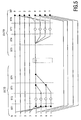
On obtient ainsi un circuit qui fonctionne en mode différentiel et dont une implémentation particulièrement économique est illustrée à la Fig. 4. Le circuit de filtrage de données selon ce mode de fonctionnement comprend 4 étages correspondant à la transformation en cosinus discrète (DCT2) :
- un premier étage (ST1) comporte 4 additionneurs effectuant, pour les lignes 4 à 7, chacun une soustraction d'une donnée d'origine X(j) de ligne j à une donnée d'origine X(7-j) de ligne (7-j), et délivrant des données transformées intermédiaires impaires ;
- un deuxième étage (ST2) comporte 2 unités de rotation (C1,C3) effectuant le traitement des données transformées intermédiaires impaires correspondant respectivement, d'une part aux lignes 5
et 6, et d'autre part aux lignes 4et 7 ; - un troisième étage (ST3) comporte 4 additionneurs effectuant dans l'ordre des lignes 4 à 7 :
- une addition des données issues des lignes 4
et 6 du deuxième étage, - une soustraction de la donnée issue de la ligne 5 du deuxième étage à celle de la
ligne 7, fournissant une donnée transformée impaire Y3, - une soustraction de la donnée issue de la ligne 6 du deuxième étage à celle de la
ligne 4, fournissant une donnée transformée impaire Y5, - une addition des données issues des lignes 5
et 7 du deuxième étage ;
- une addition des données issues des lignes 4
- un quatrième étage (ST4) comportant 2 additionneurs effectuant :
- pour
la ligne 4, une soustraction de la donnée issue de la ligne 4 du troisième étage à celle issue de laligne 7, fournissant une donnée transformée impaire Y7, - pour
la ligne 7, une addition des données issues des lignes 4et 7 du troisième étage, fournissant une donnée transformée impaire Y1.
- pour
- a first stage (ST1) comprises 4 adders performing, for the
lines 4 to 7, each subtraction of an original datum X (j) of line j to an original datum X (7-j) of line ( 7-j), and delivering odd intermediate transformed data; - a second stage (ST2) comprises 2 rotation units (C1, C3) processing the odd intermediate transformed data corresponding respectively to
lines lines - a third stage (ST3) has 4 adders performing in the order of
lines 4 to 7:- an addition of data from
rows - a subtraction of the data from
line 5 of the second stage to that ofline 7, providing an odd transformed data Y3, - a subtraction of the data from
line 6 of the second stage to that ofline 4, providing an odd transformed data Y5, - an addition of data from
rows
- an addition of data from
- a fourth stage (ST4) having 2 adders performing:
- for
line 4, a subtraction of the data fromline 4 of the third stage to that fromline 7, providing an odd transformed data Y7, - for
line 7, an addition of the data fromlines
- for
Une unité de correction (ZER) des données transformées impaires est réalisée avec 4 circuits logiques réalisant la fonction 'ET'. Les entrées des circuits logiques'ET'sont d'une part Y1, Y3, Y5 et Y7, et d'autre part une valeur de sortie opposée à la valeur fournie par un circuit de calcul PRED d'une fréquence maximale prédite. Cette valeur de sortie est 1 si la donnée transformée impaire YZ est de fréquence supérieure à la fréquence maximale prédite et 0 dans le cas contraire YNZ. Les données transformées corrigées impaires issues des'ET' logiques sont donc soit des données transformées impaires YZ devant être mises à zéro, soit 0. Autrement dit, l'unité de correction (ZER) annule les données transformées impaires YNZ autres que celles YZ devant être mises à zéro.A correction unit (ZER) of the odd transformed data is performed with 4 logic circuits performing the 'AND' function. The inputs of the logic circuits are on the one hand Y1, Y3, Y5 and Y7, and on the other hand an output value opposite the value provided by a PRED calculation circuit of a predicted maximum frequency. This output value is 1 if the odd transformed data YZ is of higher frequency than the maximum predicted frequency and 0 otherwise YNZ. The odd corrected transformed data resulting from the logical'ET 'are therefore either odd transformed data YZ to be zeroed or 0. In other words, the correction unit (ZER) cancels the odd transformed data YNZ other than those YZ before be set to zero.
Ainsi, les h données impaires, avec h compris ici entre 0 et 4, dont la fréquence est supérieure à la fréquence maximale prédite ne sont pas corrigées tandis que les autres données impaires sont mises à zéro afin d'être traitée par la transformation discrète inverse (IDCT2) de manière à générer les données différentielles DX.Thus, the odd data, with h included here between 0 and 4, whose frequency is greater than the maximum predicted frequency, are not corrected while the other odd data are set to zero in order to be processed by the inverse discrete transformation. (IDCT2) so as to generate the differential data DX.
Le circuit de filtrage de données selon ce mode de réalisation comprend enfin 4 étages correspondant à la transformation en cosinus discrète inverse (IDCT2) :
- un cinquième étage (ST5) comportant 2 additionneurs effectuant sur les données transformées impaires corrigées :
- pour
la ligne 4, une soustraction de la donnée issue de la ligne 4 de l'unité de correction à celle issue de laligne 7, - pour
la ligne 7, une addition des données issues des lignes 4et 7 de l'unité de correction ;
- pour
- un sixième étage (ST6) comportant 4 additionneurs effectuant dans l'ordre des lignes 4 à 7 :
- une addition des données issues des lignes 4
et 6 du cinquième étage, - une soustraction de la donnée issue de la ligne 5 du cinquième étage à celle issue de la
ligne 7, - une soustraction de la donnée issue de la ligne 6 du cinquième étage à celle issue de la
ligne 4, - une addition des données issues des lignes 5
et 7 du cinquième étage ;
- une addition des données issues des lignes 4
- un septième étage (ST7)
comportant 2 unités de rotation (C1,C3) effectuant le traitement des données issues du premier étage correspondant respectivement, d'une part aux lignes 5et 6, et d'autre part aux lignes 4et 7, et délivrant des données filtrées intermédiaires ; - un huitième et dernier étage (ST8) comportant 8 additionneurs effectuant chacun :
- pour les lignes j=0 à 3, une soustraction d'une donnée filtrée intermédiaire de ligne (7-j) à la donnée d'origine X(j) de ligne j,
- pour les lignes j=4 à 7, une addition d'une donnée filtrée intermédiaire de ligne j et de la donnée d'origine X(j) de même ligne.
- a fifth stage (ST5) having 2 adders performing on the corrected odd transformed data:
- for
line 4, a subtraction of the data fromline 4 of the correction unit to that fromline 7, - for
line 7, an addition of the data fromlines
- for
- a sixth stage (ST6) having 4 adders performing in the order of
lines 4 to 7:- an addition of data from
rows - a subtraction of the data from
line 5 of the fifth floor to that fromline 7, - a subtraction of the data from
line 6 of the fifth floor to that fromline 4, - an addition of data from
lines
- an addition of data from
- a seventh stage (ST7) having two rotational units (C1, C3) processing the data from the first stage corresponding respectively to
lines lines - an eighth and last floor (ST8) having 8 adders each performing:
- for the lines j = 0 to 3, a subtraction of an intermediate filtered data of line (7-j) to the original data X (j) of line j,
- for the lines j = 4 to 7, an addition of an intermediate filtered data of line j and the original data X (j) of the same line.
Le dernier étage agit alors comme un étage différentiel, apte à soustraire les données filtrées intermédiaires issues du septième étage à une première moitié des données d'origine (X0-X3) et à ajouter lesdites données filtrées intermédiaires à une seconde moitié des données d'origine (X4-X7).The last stage then acts as a differential stage, able to subtract the intermediate filtered data from the seventh floor to a first half of the data. of origin (X0-X3) and to add said intermediate filtered data to a second half of the original data (X4-X7).
De plus, grâce à la linéarité des transformations en cosinus discrète directe et Inverse, les multiplications effectuées par les quatrième et cinquième étages de la Fig. 3 ont également été supprimées car elles n'affectent pas le résultat final.Moreover, thanks to the linearity of the direct and inverse discrete cosine transformations, the multiplications performed by the fourth and fifth stages of FIG. 3 have also been deleted because they do not affect the final result.
Dans le cas du mode de réalisation de la Fig. 4, le nombre d'opérations est égal à 48, c'est à dire 36 additions et 12 multiplications, soit 32 opérations de moins que le mode de réalisation conventionnel de la Fig. 3.In the case of the embodiment of FIG. 4, the number of operations is equal to 48, ie 36 additions and 12 multiplications, ie 32 operations less than the conventional embodiment of FIG. 3.
Le circuit peut être simplifié dans certains cas particuliers. Par exemple, lorsqu'une minorité de données transformées impaires doit être mise à zéro, Il est possible de remplacer avantageusement le chemin de traitement de la seconde moitié de données (X4-X7 vers XF4-XF7) de la Fig. 4 par un chemin de traitement plus simple.The circuit can be simplified in some special cases. For example, when a minority of odd transformed data must be set to zero, it is possible to advantageously replace the processing path of the second half of data (X4-X7 to XF4-XF7) of FIG. 4 by a simpler processing path.
La Fig. 5 représente une simplification du circuit de la Fig. 4 quand seule une donnée transformée impaire YZ7 correspondant à la fréquence maximale, k=7 dans notre cas, doit être mise à zéro.Fig. 5 represents a simplification of the circuit of FIG. 4 when only an odd transformed data YZ7 corresponding to the maximum frequency, k = 7 in our case, must be set to zero.
Le premier étage (ST1) et le dernier étage restent Inchangés par rapport au circuit de la Fig. 4. En revanche, le deuxième étage (ST2) du circuit de filtrage de données selon ce mode de réalisation comporte maintenant 4 multiplieurs, chaque donnée transformée intermédiaire Impaire étant multipliée par un coefficient multiplicatif. Le troisième étage (ST3) comporte 2 additionneurs effectuant respectivement la somme, d'une part des données issues des lignes 4 et 5 du deuxième étage, et d'autre part des données issues des lignes 6 et 7 du deuxième étage. Le quatrième étage (ST4) effectue l'addition des résultats de ces deux additionneurs, formant ainsi la donnée transformée impaire YZ7. Le cinquième étage (ST5) ne fait rien. Le sixième (ST6) étage duplique la donnée transformée Impaire YZ7 pour les lignes 4 à 7 et le septième étage (ST7) multiplie chaque donnée dupliquée par un coefficient multiplicatif.The first stage (ST1) and the last stage remain unchanged with respect to the circuit of FIG. 4. On the other hand, the second stage (ST2) of the data filtering circuit according to this embodiment now comprises 4 multipliers, each intermediate transformed data Odd being multiplied by a multiplicative coefficient. The third stage (ST3) comprises two adders respectively carrying out the sum, on the one hand data from
Dans le cas du mode de réalisation de la Fig. 5, le nombre d'opérations n'est plus que de 25, c'est à dire 17 additions et 8 multiplications.In the case of the embodiment of FIG. 5, the number of operations is only 25, that is 17 additions and 8 multiplications.
Dans un autre exemple, une majorité de données transformées impaires doit être mise à zéro. La Fig. 6 représente une simplification du circuit de la Fig. 4 quand seule la donnée transformée impaire YNZ1 correspondant à la fréquence impaire minimale k=1 ne doit pas être mise à zéro.In another example, a majority of odd transformed data must be set to zero. Fig. 6 represents a simplification of the circuit of FIG. 4 when only the odd transformed data YNZ1 corresponding to the minimum odd frequency k = 1 should not be set to zero.
Le premier étage (ST1) reste inchangé par rapport au circuit de la Fig. 4. Le deuxième étage (ST2) du circuit de filtrage de données selon ce mode de réalisation comporte désormais 4 multiplieurs, chaque donnée transformée intermédiaire impaire étant multipliée par un coefficient multiplicatif. Le troisième étage (ST3) comporte 2 additionneurs effectuant respectivement la somme, d'une part des données issues des lignes 4 et 5 du deuxième étage, et d'autre part des données issues des lignes 6 et 7 du deuxième étage. Le quatrième étage (ST4) réalise l'addition des résultats de ces deux additionneurs, formant ainsi la donnée transformée impaire YNZ1. Le cinquième étage (ST5) duplique l'opposé de la donnée transformée YNZ1 pour les lignes 4 à 7. Le sixième étage (ST6) multiplie chaque donnée dupliquée par un coefficient multiplicatif. Le septième étage (ST7) comporte 4 additionneurs effectuant chacun une somme d'une donnée multipliée et d'une donnée transformée intermédiaire impaire de même ligne. Le huitième et dernier étage (ST8) comporte 8 additionneurs, 4 additionneurs effectuant les mêmes soustractions qu'à la Fig. 4 pour les lignes 0 à 3, et 4 additionneurs effectuant chacun une soustraction d'une donnée filtrée intermédiaire de ligne j à une donnée d'origine X(j) de même ligne pour les lignes 4 à 7.The first stage (ST1) remains unchanged with respect to the circuit of FIG. 4. The second stage (ST2) of the data filtering circuit according to this embodiment now comprises 4 multipliers, each odd intermediate transformed data being multiplied by a multiplicative coefficient. The third floor (ST3) has 2 adders respectively carrying out the sum, on the one hand data from
Dans le cas du mode de réalisation de la Fig. 6, le nombre d'opérations est égal à 29, c'est à dire 21 additions et 8 multiplications.In the case of the embodiment of FIG. 6, the number of operations is equal to 29, that is 21 additions and 8 multiplications.
Les circuits tels que ceux décrits aux Fig. 4 5, 6 peuvent être mis en oeuvre dans un dispositif de filtrage de données, un circuit de contrôle permettant de sélectionner le circuit adapté parmi cet ensemble de circuits en fonction du nombre h de données transformées impaires devant être mises à zéro.Circuits such as those described in FIGS. 4, 5, 6 may be implemented in a data filtering device, a control circuit for selecting the adapted circuit from this set of circuits as a function of the number h of odd transformed data to be set to zero.
Le circuit de filtrage selon l'invention peut être intégré soit comme unité de sortie d'un décodeur vidéo, soit comme unité d'entrée d'un récepteur de télévision, afin de traiter des données numériques décodées.The filtering circuit according to the invention can be integrated either as an output unit of a video decoder or as an input unit of a television receiver, in order to process decoded digital data.
La présente invention a été réalisée dans le cadre de l'implémentation du procédé de filtrage de données de l'état de la technique antérieure. Les simplifications apportées à l'architecture de filtrage permettent également d'améliorer ledit procédé de filtrage de données.The present invention has been realized as part of the implementation of the data filtering method of the state of the art. The simplifications made to the filtering architecture also make it possible to improve said data filtering method.
La présente invention concerne donc un procédé de filtrage d'un ensemble de données d'origine (X0-X7) comprenant en séries les étapes de :
- transformation discrète (DCT2) comportant une première sous-étape (ST1) apte à traiter les données d'origine et à délivrer des données transformées intermédiaires impaires, et un ensemble de sous-étapes (ST2 à ST4) apte à traiter les données transformées intermédiaires impaires et à délivrer des données transformées impaires,
- correction (ZER) apte à traiter les données transformées impaires, et à délivrer des données transformées corrigées impaires en annulant les données transformées impaires autres que celles devant être mises à zéro, et
- transformation discrète inverse (IDCT2) comportant un ensemble de sous-étapes (ST5 à ST7) apte à traiter les données transformées corrigées impaires et à délivrer des données filtrées intermédiaires, et une dernière sous-étape (ST8) apte à traiter les données d'origine (X0-X7) et les données filtrées intermédiaires.
- discrete transformation (DCT2) comprising a first substep (ST1) able to process the original data and to deliver intermediate transformed data odd, and a set of sub-steps (ST2 to ST4) adapted to process the odd intermediate transformed data and to output odd transformed data,
- correction (ZER) adapted to process the odd transformed data, and to output odd corrected transform data by canceling the odd transformed data other than those to be reset, and
- inverse discrete transformation (IDCT2) comprising a set of substeps (ST5 to ST7) able to process the odd corrected transform data and to deliver intermediate filtered data, and a last substep (ST8) able to process the data of origin (X0-X7) and the intermediate filtered data.
La diminution du nombre des opérations effectuées par chacun des procédés de filtrage permet d'économiser les ressources de calcul ou d'accélérer le temps de traitement des données d'origine.Reducing the number of operations performed by each of the filtering processes saves computing resources or speeds up the processing time of the original data.
Il existe de nombreuses manières pour implémenter les étapes précédemment décrites au moyen de logiciel. Il est possible d'implémenter ces étapes au moyen d'un circuit de décodeur vidéo ou d'un circuit de récepteur de télévision, ledit circuit étant convenablement programmé. Un jeu d'instructions contenu dans une mémoire de programmation peut provoquer le circuit à effectuer les différentes étapes précédemment décrites. Le jeu d'instructions peut aussi être chargé dans la mémoire de programmation par la lecture d'un support de données comme, par exemple un disque qui contient le jeu d'instructions. La lecture peut également s'effectuer par l'intermédiaire d'un réseau de communication comme, par exemple, le réseau internet. Dans ce cas, un fournisseur de service mettra le jeu d'instructions à la disposition des intéressés.There are many ways to implement the previously described steps using software. It is possible to implement these steps by means of a video decoder circuit or a television receiver circuit, said circuit being suitably programmed. An instruction set contained in a programming memory may cause the circuit to perform the various steps previously described. The instruction set can also be loaded into the programming memory by reading a data medium such as, for example, a disk that contains the instruction set. Reading can also be done via a network of communication like, for example, the internet network. In this case, a service provider will make the instruction set available to interested parties.
Aucun signe de référence entre parenthèses dans le présent texte ne doit être interprété de façon limitative. Le verbe "comprendre" et ses conjugaisons n'exclut pas la présence d'autres éléments ou étapes que ceux listés dans une phrase. Le mot "un" ou "une" précédant un élément ou une étape n'exclut pas la présence d'une pluralité de ces éléments ou de ces étapes.No reference sign in parentheses in this text should be interpreted in a limiting manner. The verb "to understand" and its conjugations does not exclude the presence of other elements or steps than those listed in a sentence. The word "one" or "one" preceding an element or step does not exclude the presence of a plurality of these elements or steps.
Claims (5)
- A circuit for filtering a set of original data (X0-X7) comprising:- a first processing stage (ST1) corresponding to a first sub-step of a discrete transformation (DCT2) and able to process the original data and to deliver odd intermediate transformed data, and a first set of processing stages (ST2 to ST4) corresponding to a set of sub-steps of the discrete transformation, able to process the odd intermediate transformed data and to deliver odd transformed data,- a correction unit (ZER) able to cancel out the odd transformed data other than those which are to be set to zero, and to deliver odd corrected transformed data, and- a second set of processing stages (ST5 to ST7) corresponding to a set of sub-steps of an inverse discrete transformation (IDCT2), able to process the odd corrected transformed data and to deliver intermediate filtered data, and a last processing stage (ST8) corresponding to a last sub-step of the inverse discrete transformation and able to process the original data (X0-X7) and the intermediate filtered data.
- A method of filtering a set of original data (XO-X7), comprising in series the steps of:- discrete transformation (DCT2) comprising a first sub-step (ST1) able to process the original data and to deliver odd intermediate transformed data, and a set of sub-steps (ST2 to ST4) able to process the odd intermediate transformed data and to deliver odd transformed data,- correction (ZER) able to process the odd transformed data and deliver odd corrected transformed data, and- inverse discrete transformation (IDCT2) comprising a set of sub-steps (ST5 to ST7) able to process the odd corrected transformed data and to deliver intermediate filtered data, characterized in that the correction step is able to cancel out the odd transformed data other than those which are to be set to zero and in that the discrete transformation step comprises a last sub-step (ST8) able to process the original data (X)-X7) and the intermediate filtered data.
- A video decoder able to deliver decoded digital data and comprising a filtering circuit as claimed in claim 1, able to process the decoded digital data in order to deliver processed digital data.
- A television receiver able to receive decoded digital data and comprising a filtering circuit as claimed in claim 1, able to process decoded digital data in order to deliver processed digital data intended to be displayed on a screen of said receiver.
- A computer program comprising a set of instructions for implementing the data filtering method as claimed in claim 2, when said program is executed by a processor.
Applications Claiming Priority (2)
| Application Number | Priority Date | Filing Date | Title |
|---|---|---|---|
| FR0112325 | 2001-09-25 | ||
| FR0112325 | 2001-09-25 |
Publications (3)
| Publication Number | Publication Date |
|---|---|
| EP1303142A2 EP1303142A2 (en) | 2003-04-16 |
| EP1303142A3 EP1303142A3 (en) | 2003-04-23 |
| EP1303142B1 true EP1303142B1 (en) | 2006-04-26 |
Family
ID=8867585
Family Applications (1)
| Application Number | Title | Priority Date | Filing Date |
|---|---|---|---|
| EP02078817A Expired - Lifetime EP1303142B1 (en) | 2001-09-25 | 2002-09-17 | Filtering circuit for video data in the frequency domain |
Country Status (6)
| Country | Link |
|---|---|
| US (1) | US7180946B2 (en) |
| EP (1) | EP1303142B1 (en) |
| JP (1) | JP2003230143A (en) |
| KR (1) | KR20030026904A (en) |
| AT (1) | ATE324748T1 (en) |
| DE (1) | DE60210894T2 (en) |
Family Cites Families (8)
| Publication number | Priority date | Publication date | Assignee | Title |
|---|---|---|---|---|
| US5168375A (en) * | 1991-09-18 | 1992-12-01 | Polaroid Corporation | Image reconstruction by use of discrete cosine and related transforms |
| US5528528A (en) * | 1993-03-29 | 1996-06-18 | Intel Corporation | Method, apparatus, and system for transforming signals |
| US5386233A (en) * | 1993-05-13 | 1995-01-31 | Intel Corporation | Method for efficient memory use |
| US5684534A (en) * | 1993-05-26 | 1997-11-04 | Intel Corporation | Task-splitting dual-processor system for motion estimation processing |
| JPH08275160A (en) * | 1995-03-27 | 1996-10-18 | Internatl Business Mach Corp <Ibm> | Discrete cosine conversion method |
| US6587590B1 (en) * | 1998-02-02 | 2003-07-01 | The Trustees Of The University Of Pennsylvania | Method and system for computing 8×8 DCT/IDCT and a VLSI implementation |
| US6324559B1 (en) * | 1998-10-16 | 2001-11-27 | Telefonaktiebolaget Lm Ericsson (Publ) | Odd-transform fast convolution |
| US6504872B1 (en) * | 2000-07-28 | 2003-01-07 | Zenith Electronics Corporation | Down-conversion decoder for interlaced video |
-
2002
- 2002-09-17 AT AT02078817T patent/ATE324748T1/en not_active IP Right Cessation
- 2002-09-17 EP EP02078817A patent/EP1303142B1/en not_active Expired - Lifetime
- 2002-09-17 DE DE60210894T patent/DE60210894T2/en not_active Expired - Fee Related
- 2002-09-20 US US10/247,923 patent/US7180946B2/en not_active Expired - Fee Related
- 2002-09-25 JP JP2002279566A patent/JP2003230143A/en not_active Withdrawn
- 2002-09-25 KR KR1020020058145A patent/KR20030026904A/en not_active Application Discontinuation
Also Published As
| Publication number | Publication date |
|---|---|
| US7180946B2 (en) | 2007-02-20 |
| EP1303142A2 (en) | 2003-04-16 |
| ATE324748T1 (en) | 2006-05-15 |
| DE60210894T2 (en) | 2006-11-30 |
| KR20030026904A (en) | 2003-04-03 |
| DE60210894D1 (en) | 2006-06-01 |
| EP1303142A3 (en) | 2003-04-23 |
| JP2003230143A (en) | 2003-08-15 |
| US20030076882A1 (en) | 2003-04-24 |
Similar Documents
| Publication | Publication Date | Title |
|---|---|---|
| US7916940B2 (en) | Processing of mosaic digital images | |
| Julliand et al. | Image noise and digital image forensics | |
| EP0531242B1 (en) | Adaptive filtering method of a signal transformed in subbands and corresponding filter device | |
| EP2174289A2 (en) | Method for processing a digital object and related system | |
| Fienup et al. | Comparison of reconstruction algorithms for images from sparse-aperture systems | |
| EP0511095B1 (en) | Coding and decoding method and apparatus for a digital signal | |
| FR2697704A1 (en) | Method and device for subband segmentation and reconstruction of a digital signal, and corresponding device | |
| FR2880453A1 (en) | METHOD AND DEVICE FOR PROCESSING IMAGE MOSAIC | |
| Hsieh et al. | Blind image deblurring based on the sparsity of patch minimum information | |
| FR2831753A1 (en) | Contrast matching method for image systems, involves forming filter ratio by filtering generated images and multiplying image by filter ratio to form adjusted image | |
| EP2656344B1 (en) | Improved filtering in the transformed domain | |
| EP3490255A1 (en) | Intelligent compression of grainy video content | |
| Li et al. | Efficient burst raw denoising with variance stabilization and multi-frequency denoising network | |
| EP1303142B1 (en) | Filtering circuit for video data in the frequency domain | |
| EP1246471A1 (en) | Device implementing joint post-processing and decoding of data | |
| EP1333680A2 (en) | Digital image processing method | |
| EP1246469A2 (en) | Method of simoultaneously downconverting and decoding of video | |
| EP1202577B1 (en) | Method of video data processing | |
| CN115272131B (en) | Image mole pattern removing system and method based on self-adaptive multispectral coding | |
| JPH0944655A (en) | Method and device for processing image | |
| EP3072081B1 (en) | Determination of the image depth map of a scene | |
| EP1261209A2 (en) | Method of noise detection in a video data stream | |
| WO2018083266A1 (en) | Method and device for digital image restoration | |
| CN115456891A (en) | Under-screen camera image restoration method based on U-shaped dynamic network | |
| FR2832568A1 (en) | SAMPLING FREQUENCY DIGITAL CONVERTER |
Legal Events
| Date | Code | Title | Description |
|---|---|---|---|
| PUAI | Public reference made under article 153(3) epc to a published international application that has entered the european phase |
Free format text: ORIGINAL CODE: 0009012 |
|
| PUAL | Search report despatched |
Free format text: ORIGINAL CODE: 0009013 |
|
| AK | Designated contracting states |
Designated state(s): AT BE BG CH CY CZ DE DK EE ES FI FR GB GR IE IT LI LU MC NL PT SE SK TR |
|
| AX | Request for extension of the european patent |
Extension state: AL LT LV MK RO SI |
|
| AK | Designated contracting states |
Designated state(s): AT BE BG CH CY CZ DE DK EE ES FI FR GB GR IE IT LI LU MC NL PT SE SK TR |
|
| AX | Request for extension of the european patent |
Extension state: AL LT LV MK RO SI |
|
| 17P | Request for examination filed |
Effective date: 20031023 |
|
| AKX | Designation fees paid |
Designated state(s): AT BE BG CH CY CZ DE DK EE ES FI FR GB GR IE IT LI LU MC NL PT SE SK TR |
|
| 17Q | First examination report despatched |
Effective date: 20050301 |
|
| GRAP | Despatch of communication of intention to grant a patent |
Free format text: ORIGINAL CODE: EPIDOSNIGR1 |
|
| GRAS | Grant fee paid |
Free format text: ORIGINAL CODE: EPIDOSNIGR3 |
|
| GRAA | (expected) grant |
Free format text: ORIGINAL CODE: 0009210 |
|
| AK | Designated contracting states |
Kind code of ref document: B1 Designated state(s): AT BE BG CH CY CZ DE DK EE ES FI FR GB GR IE IT LI LU MC NL PT SE SK TR |
|
| PG25 | Lapsed in a contracting state [announced via postgrant information from national office to epo] |
Ref country code: IT Free format text: LAPSE BECAUSE OF FAILURE TO SUBMIT A TRANSLATION OF THE DESCRIPTION OR TO PAY THE FEE WITHIN THE PRESCRIBED TIME-LIMIT;WARNING: LAPSES OF ITALIAN PATENTS WITH EFFECTIVE DATE BEFORE 2007 MAY HAVE OCCURRED AT ANY TIME BEFORE 2007. THE CORRECT EFFECTIVE DATE MAY BE DIFFERENT FROM THE ONE RECORDED. Effective date: 20060426 Ref country code: NL Free format text: LAPSE BECAUSE OF FAILURE TO SUBMIT A TRANSLATION OF THE DESCRIPTION OR TO PAY THE FEE WITHIN THE PRESCRIBED TIME-LIMIT Effective date: 20060426 Ref country code: AT Free format text: LAPSE BECAUSE OF FAILURE TO SUBMIT A TRANSLATION OF THE DESCRIPTION OR TO PAY THE FEE WITHIN THE PRESCRIBED TIME-LIMIT Effective date: 20060426 Ref country code: CZ Free format text: LAPSE BECAUSE OF FAILURE TO SUBMIT A TRANSLATION OF THE DESCRIPTION OR TO PAY THE FEE WITHIN THE PRESCRIBED TIME-LIMIT Effective date: 20060426 Ref country code: FI Free format text: LAPSE BECAUSE OF FAILURE TO SUBMIT A TRANSLATION OF THE DESCRIPTION OR TO PAY THE FEE WITHIN THE PRESCRIBED TIME-LIMIT Effective date: 20060426 Ref country code: IE Free format text: LAPSE BECAUSE OF FAILURE TO SUBMIT A TRANSLATION OF THE DESCRIPTION OR TO PAY THE FEE WITHIN THE PRESCRIBED TIME-LIMIT Effective date: 20060426 Ref country code: SK Free format text: LAPSE BECAUSE OF FAILURE TO SUBMIT A TRANSLATION OF THE DESCRIPTION OR TO PAY THE FEE WITHIN THE PRESCRIBED TIME-LIMIT Effective date: 20060426 |
|
| REG | Reference to a national code |
Ref country code: GB Ref legal event code: FG4D Free format text: NOT ENGLISH |
|
| REG | Reference to a national code |
Ref country code: IE Ref legal event code: FG4D Free format text: LANGUAGE OF EP DOCUMENT: FRENCH |
|
| REF | Corresponds to: |
Ref document number: 60210894 Country of ref document: DE Date of ref document: 20060601 Kind code of ref document: P |
|
| GBT | Gb: translation of ep patent filed (gb section 77(6)(a)/1977) |
Effective date: 20060605 |
|
| PG25 | Lapsed in a contracting state [announced via postgrant information from national office to epo] |
Ref country code: SE Free format text: LAPSE BECAUSE OF FAILURE TO SUBMIT A TRANSLATION OF THE DESCRIPTION OR TO PAY THE FEE WITHIN THE PRESCRIBED TIME-LIMIT Effective date: 20060726 Ref country code: DK Free format text: LAPSE BECAUSE OF FAILURE TO SUBMIT A TRANSLATION OF THE DESCRIPTION OR TO PAY THE FEE WITHIN THE PRESCRIBED TIME-LIMIT Effective date: 20060726 |
|
| PG25 | Lapsed in a contracting state [announced via postgrant information from national office to epo] |
Ref country code: ES Free format text: LAPSE BECAUSE OF FAILURE TO SUBMIT A TRANSLATION OF THE DESCRIPTION OR TO PAY THE FEE WITHIN THE PRESCRIBED TIME-LIMIT Effective date: 20060806 |
|
| PG25 | Lapsed in a contracting state [announced via postgrant information from national office to epo] |
Ref country code: PT Free format text: LAPSE BECAUSE OF FAILURE TO SUBMIT A TRANSLATION OF THE DESCRIPTION OR TO PAY THE FEE WITHIN THE PRESCRIBED TIME-LIMIT Effective date: 20060926 |
|
| PGFP | Annual fee paid to national office [announced via postgrant information from national office to epo] |
Ref country code: GB Payment date: 20060926 Year of fee payment: 5 |
|
| PG25 | Lapsed in a contracting state [announced via postgrant information from national office to epo] |
Ref country code: MC Free format text: LAPSE BECAUSE OF NON-PAYMENT OF DUE FEES Effective date: 20060930 Ref country code: CH Free format text: LAPSE BECAUSE OF NON-PAYMENT OF DUE FEES Effective date: 20060930 Ref country code: BE Free format text: LAPSE BECAUSE OF NON-PAYMENT OF DUE FEES Effective date: 20060930 Ref country code: LI Free format text: LAPSE BECAUSE OF NON-PAYMENT OF DUE FEES Effective date: 20060930 |
|
| NLV1 | Nl: lapsed or annulled due to failure to fulfill the requirements of art. 29p and 29m of the patents act | ||
| PGFP | Annual fee paid to national office [announced via postgrant information from national office to epo] |
Ref country code: DE Payment date: 20061110 Year of fee payment: 5 |
|
| REG | Reference to a national code |
Ref country code: IE Ref legal event code: FD4D |
|
| PLBE | No opposition filed within time limit |
Free format text: ORIGINAL CODE: 0009261 |
|
| STAA | Information on the status of an ep patent application or granted ep patent |
Free format text: STATUS: NO OPPOSITION FILED WITHIN TIME LIMIT |
|
| 26N | No opposition filed |
Effective date: 20070129 |
|
| REG | Reference to a national code |
Ref country code: CH Ref legal event code: PL |
|
| BERE | Be: lapsed |
Owner name: KONINKLIJKE PHILIPS ELECTRONICS N.V. Effective date: 20060930 |
|
| PG25 | Lapsed in a contracting state [announced via postgrant information from national office to epo] |
Ref country code: GR Free format text: LAPSE BECAUSE OF FAILURE TO SUBMIT A TRANSLATION OF THE DESCRIPTION OR TO PAY THE FEE WITHIN THE PRESCRIBED TIME-LIMIT Effective date: 20060727 |
|
| GBPC | Gb: european patent ceased through non-payment of renewal fee |
Effective date: 20070917 |
|
| PG25 | Lapsed in a contracting state [announced via postgrant information from national office to epo] |
Ref country code: BG Free format text: LAPSE BECAUSE OF FAILURE TO SUBMIT A TRANSLATION OF THE DESCRIPTION OR TO PAY THE FEE WITHIN THE PRESCRIBED TIME-LIMIT Effective date: 20060726 Ref country code: EE Free format text: LAPSE BECAUSE OF FAILURE TO SUBMIT A TRANSLATION OF THE DESCRIPTION OR TO PAY THE FEE WITHIN THE PRESCRIBED TIME-LIMIT Effective date: 20060426 |
|
| PG25 | Lapsed in a contracting state [announced via postgrant information from national office to epo] |
Ref country code: DE Free format text: LAPSE BECAUSE OF NON-PAYMENT OF DUE FEES Effective date: 20080401 Ref country code: TR Free format text: LAPSE BECAUSE OF FAILURE TO SUBMIT A TRANSLATION OF THE DESCRIPTION OR TO PAY THE FEE WITHIN THE PRESCRIBED TIME-LIMIT Effective date: 20060426 Ref country code: LU Free format text: LAPSE BECAUSE OF NON-PAYMENT OF DUE FEES Effective date: 20060917 |
|
| REG | Reference to a national code |
Ref country code: FR Ref legal event code: ST Effective date: 20080531 |
|
| PG25 | Lapsed in a contracting state [announced via postgrant information from national office to epo] |
Ref country code: FR Free format text: LAPSE BECAUSE OF NON-PAYMENT OF DUE FEES Effective date: 20071001 |
|
| PGFP | Annual fee paid to national office [announced via postgrant information from national office to epo] |
Ref country code: FR Payment date: 20060929 Year of fee payment: 5 |
|
| PG25 | Lapsed in a contracting state [announced via postgrant information from national office to epo] |
Ref country code: CY Free format text: LAPSE BECAUSE OF FAILURE TO SUBMIT A TRANSLATION OF THE DESCRIPTION OR TO PAY THE FEE WITHIN THE PRESCRIBED TIME-LIMIT Effective date: 20060426 Ref country code: GB Free format text: LAPSE BECAUSE OF NON-PAYMENT OF DUE FEES Effective date: 20070917 |