EP1303033B1 - Controller input voltage regulation by actuator power modulation - Google Patents
Controller input voltage regulation by actuator power modulation Download PDFInfo
- Publication number
- EP1303033B1 EP1303033B1 EP02020108A EP02020108A EP1303033B1 EP 1303033 B1 EP1303033 B1 EP 1303033B1 EP 02020108 A EP02020108 A EP 02020108A EP 02020108 A EP02020108 A EP 02020108A EP 1303033 B1 EP1303033 B1 EP 1303033B1
- Authority
- EP
- European Patent Office
- Prior art keywords
- voltage
- controller
- predefined
- actuator
- control
- Prior art date
- Legal status (The legal status is an assumption and is not a legal conclusion. Google has not performed a legal analysis and makes no representation as to the accuracy of the status listed.)
- Expired - Lifetime
Links
Images

Classifications
-
- H—ELECTRICITY
- H02—GENERATION; CONVERSION OR DISTRIBUTION OF ELECTRIC POWER
- H02J—ELECTRIC POWER NETWORKS; CIRCUIT ARRANGEMENTS OR SYSTEMS FOR SUPPLYING OR DISTRIBUTING ELECTRIC POWER; SYSTEMS FOR STORING ELECTRIC ENERGY
- H02J1/00—Circuit arrangements for DC mains or DC distribution networks
-
- H—ELECTRICITY
- H02—GENERATION; CONVERSION OR DISTRIBUTION OF ELECTRIC POWER
- H02M—APPARATUS FOR CONVERSION BETWEEN AC AND AC, BETWEEN AC AND DC, OR BETWEEN DC AND DC, AND FOR USE WITH MAINS OR SIMILAR POWER SUPPLY SYSTEMS; CONVERSION OF DC OR AC INPUT POWER INTO SURGE OUTPUT POWER; CONTROL OR REGULATION THEREOF
- H02M7/00—Conversion of AC power input into DC power output; Conversion of DC power input into AC power output
- H02M7/42—Conversion of DC power input into AC power output without possibility of reversal
- H02M7/44—Conversion of DC power input into AC power output without possibility of reversal by static converters
- H02M7/48—Conversion of DC power input into AC power output without possibility of reversal by static converters using discharge tubes with control electrode or semiconductor devices with control electrode
- H02M7/53—Conversion of DC power input into AC power output without possibility of reversal by static converters using discharge tubes with control electrode or semiconductor devices with control electrode using devices of a triode or transistor type requiring continuous application of a control signal
- H02M7/537—Conversion of DC power input into AC power output without possibility of reversal by static converters using discharge tubes with control electrode or semiconductor devices with control electrode using devices of a triode or transistor type requiring continuous application of a control signal using semiconductor devices only, e.g. single switched pulse inverters
- H02M7/5387—Conversion of DC power input into AC power output without possibility of reversal by static converters using discharge tubes with control electrode or semiconductor devices with control electrode using devices of a triode or transistor type requiring continuous application of a control signal using semiconductor devices only, e.g. single switched pulse inverters in a bridge configuration
- H02M7/53871—Conversion of DC power input into AC power output without possibility of reversal by static converters using discharge tubes with control electrode or semiconductor devices with control electrode using devices of a triode or transistor type requiring continuous application of a control signal using semiconductor devices only, e.g. single switched pulse inverters in a bridge configuration with automatic control of output voltage or current
-
- B—PERFORMING OPERATIONS; TRANSPORTING
- B60—VEHICLES IN GENERAL
- B60R—VEHICLES, VEHICLE FITTINGS, OR VEHICLE PARTS, NOT OTHERWISE PROVIDED FOR
- B60R16/00—Electric or fluid circuits specially adapted for vehicles and not otherwise provided for; Arrangement of elements of electric or fluid circuits specially adapted for vehicles and not otherwise provided for
- B60R16/02—Electric or fluid circuits specially adapted for vehicles and not otherwise provided for; Arrangement of elements of electric or fluid circuits specially adapted for vehicles and not otherwise provided for electric constitutive elements
- B60R16/03—Electric or fluid circuits specially adapted for vehicles and not otherwise provided for; Arrangement of elements of electric or fluid circuits specially adapted for vehicles and not otherwise provided for electric constitutive elements for supply of electrical power to vehicle subsystems or for
-
- H—ELECTRICITY
- H02—GENERATION; CONVERSION OR DISTRIBUTION OF ELECTRIC POWER
- H02J—ELECTRIC POWER NETWORKS; CIRCUIT ARRANGEMENTS OR SYSTEMS FOR SUPPLYING OR DISTRIBUTING ELECTRIC POWER; SYSTEMS FOR STORING ELECTRIC ENERGY
- H02J2105/00—Networks for supplying or distributing electric power characterised by their spatial reach or by the load
- H02J2105/30—Networks for supplying or distributing electric power characterised by their spatial reach or by the load the load networks being external to vehicles, i.e. exchanging power with vehicles
- H02J2105/33—Networks for supplying or distributing electric power characterised by their spatial reach or by the load the load networks being external to vehicles, i.e. exchanging power with vehicles exchanging power with road vehicles
-
- H—ELECTRICITY
- H02—GENERATION; CONVERSION OR DISTRIBUTION OF ELECTRIC POWER
- H02M—APPARATUS FOR CONVERSION BETWEEN AC AND AC, BETWEEN AC AND DC, OR BETWEEN DC AND DC, AND FOR USE WITH MAINS OR SIMILAR POWER SUPPLY SYSTEMS; CONVERSION OF DC OR AC INPUT POWER INTO SURGE OUTPUT POWER; CONTROL OR REGULATION THEREOF
- H02M1/00—Details of apparatus for conversion
- H02M1/0003—Details of control, feedback or regulation circuits
- H02M1/0016—Control circuits providing compensation of output voltage deviations using feedforward of disturbance parameters
- H02M1/0022—Control circuits providing compensation of output voltage deviations using feedforward of disturbance parameters the disturbance parameters being input voltage fluctuations
Definitions
- Mechanical linkage and hydraulic pressure operated controls for vehicles are well known in the art, and generally comprise control input devices operated by a user such as steering wheels, shift levers, and foot pedals which are directly interlinked with various vehicle controls individually or by combinations of mechanical push rods, gears, cables, or pressurized hydraulic systems.
- Such controls have been utilized in vehicles such as automobiles and trucks since the inception and initial manufacturer of such vehicles.
- Fig. 2 represents an analog circuit that represents one possible embodiment of a low Voltage Control Circuit 16 for regulating the voltage of the electrical signal in loop 13 above a predefined minimum.
- the predefined minimum voltage is some voltage greater than the minimum operation voltage requirement for controller 14.
- controller 14 can be prevented from entering a reset mode as a result of a voltage dip occurring during a high current demand request by motor 20.
- the bus voltage to be regulated comes into circuit 16 as the SWBAT input 30.
- the +5V signal 32 provides a control reference for circuit 16.
- the VREG* signal is an output from circuit 16 as a signal to indicate to system 10 that the power bus 12 voltage has dipped and the voltage regulation function of circuit 16 is modifying the original current request.
- VREG* 34 is a logic "1"
- the voltage control circuitry is off and the system 10 is in normal operation.
- VREG* is a logic "0”
- the voltage control circuitry is active and the system is in a reduced output capability condition.
- circuit 16 represents but one embodiment of an analog circuit to perform a voltage limiting function, and those skilled in the art will recognize that other variations of circuit 16 will perform a like function.
- the monitoring of reduction percentage is illustrated at 208. If the reduction percentage is less than or equal to the maximum, the load current reduction is performed to the calculated level at 210 and transmitted to summer 124. If, on the other hand, the calculated load current reduction is greater than the maximum, the load current reduction is set to the maximum permitted at 212 and transmitted to summer 124.
- the maximum load current reduction must be defined as a system condition to maintain proper system operation.
Landscapes
- Engineering & Computer Science (AREA)
- Power Engineering (AREA)
- Electric Propulsion And Braking For Vehicles (AREA)
- Direct Current Feeding And Distribution (AREA)
- Dc-Dc Converters (AREA)
Description
- The present invention generally relates to vehicle electrical systems and in particular to methods and circuitry for regulating vehicle control system voltages.
- Such a system is disclosed in the japanese patent JP11334497.
- Mechanical linkage and hydraulic pressure operated controls for vehicles are well known in the art, and generally comprise control input devices operated by a user such as steering wheels, shift levers, and foot pedals which are directly interlinked with various vehicle controls individually or by combinations of mechanical push rods, gears, cables, or pressurized hydraulic systems. Such controls have been utilized in vehicles such as automobiles and trucks since the inception and initial manufacturer of such vehicles. As technology through the years has advanced, so also have these mechanical linkage and hydraulic pressure systems advanced with newer and more advanced innovations. Newer forms of technology wherein every vehicle now has one or more on-board computers in various forms assisting in vehicle operation and control. These computers through interconnection with various sensors and vehicle controls can rapidly acquire various objective input data, analyze this data, and then appropriately adjust the vehicle controls to more readily optimize the operation of the various vehicle systems and controls. As a result of the rapid computational power and speed of the computers, control commands can be issued at a much faster rate than older technology mechanical system configurations can respond. The requirement for increased control response time were initially felt in the aerospace industry where modem aircraft have evolved from the use of mechanically linked controls to electrically operated controls in a concept commonly known as "fly-by-wire".
- As the quest for more and more improvements in vehicle efficiency, more accurate controls, and improved response times, the automotive and vehicle industries are turning with greater frequency to additional electronics and electrical systems to provide necessary vehicle controls. Initially, implementation of various electrical control systems was limited to vehicle systems such as power windows and power door locks, the industry is now moving to replace mechanically operated, systems with electrically operated systems. Braking systems, for example, is potentially one such system. Previously, to ensure the integrity of a vehicle system such as brakes one only had to ensure that the mechanical linkages were secure and properly adjusted and that the brake hydraulic system also maintained its integrity. With the implementation of electrical and electronic controls, maintenance of electric power to vehicle systems is now paramount.
- For example, by switching the vehicle braking system from one of mechanical linkages and hydraulic pressure systems to a purely electrical system, the only interconnection between the driver and the individual brakes at the four corners of the vehicle are electrical conductors. The input voltage to a load in such a system dips at the input terminals due to the current draw of the load through impedances from wiring, connectors, and the power source (battery or alternator). Large load current spikes cause severe voltage dips in the system, and some of these voltage dips may be severe enough to cause controller "brown outs" or resets. Consequently, in a purely electrical control of a vehicle system special attention must be paid to the fail-safe conditions of the electrical system.
- Therefore, maintaining operability during various system failure modes generally requires that some minimum amount of electric power be supplied to the various components to preclude the total loss of the system and potential loss of control of the vehicle as a result of the voltage "brown outs" or controller resets. Such instances of power dissipation, voltage dips, and voltage transients which individually or in some combination can have the combined effect of failing to meet the basic functionality of the system. One such effect could be causing a microprocessor system to reset thereby causing that system or that portion of the system to go off-line and thus its function become unavailable to the vehicle operator. Similar problems exist in the event of the failure of the on-board electric power generation system such that the vehicle must rely strictly on available stored battery power. In this case, system availability remains paramount even though the systems must operate in a degraded mode to maintain that availability. Thus, there is a need to provide a methodology by which the basic characteristics of the electric power are maintained to prevent, to the greatest extent possible, the failure or operational cessation of electrical systems on a vehicle.
- One aspect of the invention is a vehicle system incorporating a voltage regulating control. The system includes a power supply providing electrical power to the system and having a predefined maximum voltage. A controller controls an actuator performing a vehicle system function and the electrical load in the system wherein the controller has a first predefined minimum operating voltage. A voltage regulator communicates with the controller and the power supply and senses a control system input voltage in the control system. In response to a voltage dip in excess of a predetermined value, the regulator reduces a current request signal from said load to maintain the system voltage at a predefined minimum voltage greater than the first predefined minimum operating voltage required by the controller.
- Another aspect of the invention is a method for regulating the voltage of a vehicle system of the type having a power supply, a controller, and an actuator. The method comprises the steps of defining a minimum system voltage; sensing system input voltage for said system during operation of the actuator; reducing a current request signal from said actuator when the sensed system input voltage approaches a predefined minimum; and limiting the system voltage to a predefined minimum.
- These and other features, advantages and objects of the present invention will be further understood and appreciated by those skilled in the art by reference to the following specification, claims, and appended drawings.
-
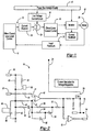
- Fig. 1 is a block diagram of a system configuration incorporating an analog embodiment of a bus voltage regulating function.
- Fig. 2 is an analog low voltage control circuit diagram of the bus voltage regulating embodiment of the system in Fig. 1.
- Fig. 3 is a block diagram of a system configuration incorporating a software controlled embodiment of a bus voltage regulating function.
- Fig. 4 is a software process flow diagram of the bus voltage regulating embodiment of the system in Fig. 3.
- Referring to Figures 1 and 2, wherein like numerals indicate like or corresponding parts throughout the several views, a vehicle system generally represented at 10.
System 10 includes apower supply 12, such as a standard 12-volt power bus, that provides electrical power to thesystem 10. A lowvoltage control circuit 16 according to one embodiment of the invention is interposed betweenpower supply 12 and acontrol loop 13 atsummer 24.Control loop 13 includes acontroller 14 into which is directed a plurality of data signals (not shown) and operator initiated control commands.Controller 14 in turn issues commands to controlloop 13 to initiate desired actions by actuator ormotor 20 for performing a desired system function such as, for example, actuating a brake, turning a wheel, or some other critical vehicle operation function.Control loop 13 further includesfeedback loops - Fig. 2 represents an analog circuit that represents one possible embodiment of a low
Voltage Control Circuit 16 for regulating the voltage of the electrical signal inloop 13 above a predefined minimum. The predefined minimum voltage is some voltage greater than the minimum operation voltage requirement forcontroller 14. By maintainingloop 13 voltage above the minimum operating voltage forcontroller 14,controller 14 can be prevented from entering a reset mode as a result of a voltage dip occurring during a high current demand request bymotor 20. The bus voltage to be regulated comes intocircuit 16 as theSWBAT input 30. The +5V signal 32 provides a control reference forcircuit 16. The VREG* signal is an output fromcircuit 16 as a signal to indicate tosystem 10 that thepower bus 12 voltage has dipped and the voltage regulation function ofcircuit 16 is modifying the original current request. When VREG* 34 is a logic "1", the voltage control circuitry is off and thesystem 10 is in normal operation. When VREG* is a logic "0", the voltage control circuitry is active and the system is in a reduced output capability condition. - Jumper 36 provides flexibility to connect
resistor 38 in parallel withresistor 40 such that the voltage regulation function may be changed to a second voltage such as switching from a 12 volt system to a 42 volt system. For example,jumper 36 is installed to operate in a 12-volt system with a regulation voltage of 7.2 volts andjumper 36 is uninstalled to operate in a 42-volt system with a regulation voltage of 25 volts. With this constraint, further description will refer toSWBAT 30 as a 42-volt system and attempt to regulate the voltage at 25 volts. -
Amplifier 42 in conjunction withresistors capacitors SWBAT voltage 30. The +5V signal 32 provides a control reference to thenon-inverting input 41 ofamplifier 42. -
Resistors Vfb 64 such that Vfb = SWBAT * 0.1992.Capacitor 66 in conjunction withresistors - Under normal system conditions, the
SWBAT 30 voltage is near 42 volts. Even with moderately high current spikes, theSWBAT 30 voltage remains significantly above the 25-volt regulation threshold. In this condition, the voltage of invertinginput 43 ofamplifier 42 is much higher than the voltage of thenon-inverting input 41. This causes the output ofamplifier 42 to saturate at 0 volts. When the output ofamplifier 42 is below the activating threshold voltage of transistor 70 (typically 2-4 volts),transistor 70 is off and has no effect on the C LIMIT value atsummer 24. Also the input toinverter 72 is a logic "0". This cause the VREG* signal 34 to be a logic "1" therefore indicating that the voltage control circuitry is off and the system is in normal operation. - As the
SWBAT voltage 30 approaches 25 volts, the voltage atVfb 64 approaches 5 volts. Under this condition, the voltage of the invertinginput 43 and thenon-inverting input 41 ofamplifier 42 become equal, andamplifier 42 enters the active state. The output ofamplifier 42 begins to rise in voltage until it reaches the activating threshold oftransistor 70. At this instant,transistor 70 begins conducting current from the CLIMIT summing node 24. This current conduction reduces the current request to the closed loopcurrent control 18, which reduces the load current draw from thepower supply 12. This is the beginning of input voltage regulation to maintain a minimum voltage at the input terminals of the system. If the load current continues to increase,SWBAT voltage 30 continues to fall lower (only by millivolts because the circuit is in closed loop control of the SWBAT voltage), and the output voltage ofamplifier 42 increases. This increase causestransistor 70 to conduct more current, which reduces the current request,C LIMIT 24, further. The increase in the output voltage of amplifier 42 (also increased conduction of transistor 70) does not permit the continued increase in the load current. This modulation continues to keep the value of theSWBAT voltage 30 near the desired threshold value of 25 volts. While the output ofamplifier 42 is above the input threshold ofinverter 72, the VREG*signal 34 is at a logic "0" indicating that the voltage control circuitry is active and the system is in a reduced output capability condition. When the load request is reduced and the SWBAT voltage begins to rise above the minimum threshold (25V), the output ofamplifier 42 returns to 0 volts, and the system returns to normal operation. - In the event that the
SWBAT voltage 30 continues to fall below the 25 volt threshold, the output ofamplifier 42 rises to the maximumvalue causing transistor 70 to enter a maximum conduction condition. Under this situation, the current draw from CLIMIT summing node 24 is forced to the maximum load current reduction value which is defined byresistor 74.Resistor 74 creates a voltage divider with the output impedance ofcurrent request circuit 15. The maximum reduction percentage is defined as the value ofresistor 74 divided by the sum ofresistor 74 andcircuit 15 resistance. As the value ofresistor 74 decreases, the maximum reduction percentage increases. - The above schematic represents but one embodiment of an analog circuit to perform a voltage limiting function, and those skilled in the art will recognize that other variations of
circuit 16 will perform a like function. - Turning now to Figures 3 and 4, another embodiment is illustrated wherein the voltage regulation function is performed in a microprocessor. Like ending numerals indicate like or corresponding parts to the system described in Figure 1 above. A vehicle system is generally represented at 110.
System 110 includes apower supply 112, such as a standard 12-volt power bus, that provides electrical power to thesystem 110. Avoltage sensing function 102 and voltagecontrol calculation function 104 arc performed inmicroprocessor 114 and function to replacecontrol circuit 16 as described in the above embodiment.Control loop 113 includes amicroprocessor controller 114 into which is directed a plurality of data signals (not shown) and operator initiated control commands.Controller 114 in turn issues commands to controlloop 113 to initiate desired actions by actuator ormotor 120 for performing a desired system function such as, for example, actuating a brake, turning a wheel, or some other critical vehicle operation function.Control loop 113 further includesfeedback loops -
Voltage Sensing 102 andVoltage Control Calculation 104 functions which replaceanalog circuit 16 in the embodiment illustrated in Figures 1 and 2 as previously noted are performed by software inmicroprocessor 114 in the instant embodiment. A flow diagram of these functions is illustrated in Figure 2 and their operation is discussed below. - Referring now to Figure 2, the
Voltage Sensing 102 andVoltage Control Calculation 104 functions are illustrated according to their respective steps. Sampling of the power bus voltage is performed at 102.Microprocessor 114 then compares the sampled voltage to predefined values which as in the previous example are illustrated as 42 volts for the power bus voltage, and a threshold voltage of 25 volts. Atstep 202,Voltage Control Calculation 104 function determines whether the sampled bus voltage is below the threshold limit of 25 volts. If not the Load Current Reduction is set at zero as shown inblock 204 and the power signal is transmitted unchanged tosummer 124. Ifdecision 202 determines that the voltage is below the 25 volt threshold, microprocessor calculates the desired load current reduction percentage at 206. The monitoring of reduction percentage is illustrated at 208. If the reduction percentage is less than or equal to the maximum, the load current reduction is performed to the calculated level at 210 and transmitted tosummer 124. If, on the other hand, the calculated load current reduction is greater than the maximum, the load current reduction is set to the maximum permitted at 212 and transmitted tosummer 124. The maximum load current reduction must be defined as a system condition to maintain proper system operation. - The above description is considered that of the preferred embodiments only. Modifications of the invention will occur to those skilled in the art and to those who make or use the invention. Therefore, it is understood that the embodiments shown in the drawings and described above are merely for illustrative purposes and not intended to limit the scope of the invention, which is defined by the following claims.
Claims (8)
- A vehicle system (10) incorporating a voltage regulating control, said system comprising:a power supply (12) providing electrical power having a first predefined maximum voltage;a controller (18) for controlling an electrical load in said system, said controller having a first predefined minimum operating voltage;a voltage regulator (16) in communication with said controller (18) and said power supply (12) wherein said regulator senses a control system input voltage In said system (10), and in response to a voltage dip in excess of a predetermined value said regulator reduces a current request signal from said load to maintain said system voltage at a second predefined minimum voltage greater than said first predefined minimum operating voltage; andsaid load is at least an actuator (20) receiving control inputs from said voltage regulating control for performing a vehicle system function and said control inputs being voltage regulated by said voltage regulating control.
- The system according to claim 1 wherein said voltage regulator (16) is an analog circuit in electrical communication with said controller (18) and said actuator (20).
- The system according to claim 2 wherein said analog circuit includes:an amplifier (42) responsive to a decreasing voltage in said system such that said amplifier becomes active when said second predefined minimum system voltage is approached, said amplifier becomes active providing an increased voltage output; anda transistor (70) responsive to said amplifier voltage output, such that said transistor enters a conductive state when an activation threshold voltage is sensed by said transistor, said conductive state of said transistor then conducting current from said system to decrease a current request for said actuator (20) and thereby maintaining a system voltage at said second minimum voltage.
- The system according to claim 3 wherein said circuit further includes a jumper (36) for selecting between alternate predefined voltage minimums.
- The system according to claim 4 wherein said circuit further includes a logical output (34) to said controller, said logical output having a first state communicating an active state of said analog circuit to said controller and a second state communicating an inactive state of said analog circuit.
- The system according to claim 1 wherein:said controller (18) is a microprocessor; andsaid voltage regulator (16) comprises software function within said microprocessor.
- The system according to claim 6 wherein said software function comprises the steps of:sampling said power supply voltage (12);calculating a current load reduction when the sampled voltage is below a predefined limit;determining whether the calculated reduction is greater than a predefined maximum;reducing the current load by the calculated reduction when the calculated reduction is less than the predefined maximum; andreducing the current load by the predefined maximum when the calculated reduction is equal to or greater than the predefined maximum.
- A method for regulating the voltage of a vehicle system of the type having a power supply (12), a controller (18), and an actuator (20), said method comprising the steps of:defining a minimum system voltage;sensing a system input voltage for said system during operation of the actuator (20);reducing a current request signal from said actuator (20) when the sensed system input voltage approaches a predefined minimum; andlimiting the system voltage to a predefined minimum.
Applications Claiming Priority (2)
| Application Number | Priority Date | Filing Date | Title |
|---|---|---|---|
| US974693 | 2001-10-09 | ||
| US09/974,693 US6624531B2 (en) | 2001-10-09 | 2001-10-09 | Controller input voltage regulation by actuator power modulation |
Publications (3)
| Publication Number | Publication Date |
|---|---|
| EP1303033A2 EP1303033A2 (en) | 2003-04-16 |
| EP1303033A3 EP1303033A3 (en) | 2004-01-21 |
| EP1303033B1 true EP1303033B1 (en) | 2006-03-29 |
Family
ID=25522343
Family Applications (1)
| Application Number | Title | Priority Date | Filing Date |
|---|---|---|---|
| EP02020108A Expired - Lifetime EP1303033B1 (en) | 2001-10-09 | 2002-09-07 | Controller input voltage regulation by actuator power modulation |
Country Status (4)
| Country | Link |
|---|---|
| US (1) | US6624531B2 (en) |
| EP (1) | EP1303033B1 (en) |
| DE (1) | DE60210181T2 (en) |
| ES (1) | ES2261569T3 (en) |
Families Citing this family (15)
| Publication number | Priority date | Publication date | Assignee | Title |
|---|---|---|---|---|
| US6704629B2 (en) * | 2001-11-30 | 2004-03-09 | Bppower, Inc. | Device for monitoring motor vehicle's electric power and method therefor |
| US7924937B2 (en) * | 2002-03-04 | 2011-04-12 | Stmicroelectronics N.V. | Resonant power converter for radio frequency transmission and method |
| KR100686421B1 (en) * | 2002-03-04 | 2007-02-23 | 에스티마이크로일렉트로닉스 엔.브이. | Coder device for resonant power conversion and method |
| US6917502B2 (en) | 2002-03-28 | 2005-07-12 | Delphi Technologies, Inc. | Power supply circuit and method for a motor vehicle electrical accessory load |
| JP2005027363A (en) * | 2003-06-30 | 2005-01-27 | Aisin Seiki Co Ltd | In-vehicle system controller |
| US7212006B2 (en) | 2004-07-02 | 2007-05-01 | Bppower, Inc. | Method and apparatus for monitoring the condition of a battery by measuring its internal resistance |
| US7525266B2 (en) * | 2006-01-30 | 2009-04-28 | Honeywell International Inc. | Inverter loop latch with integrated AC detection reset |
| US20070194791A1 (en) | 2006-02-17 | 2007-08-23 | Bppower Inc. | Method and apparatus for monitoring the condition of a battery by measuring its internal resistance |
| US7928735B2 (en) | 2007-07-23 | 2011-04-19 | Yung-Sheng Huang | Battery performance monitor |
| US8049372B2 (en) * | 2008-07-01 | 2011-11-01 | GM Global Technology Operations LLC | Precharging a high-voltage bus using a voltage-regulated power supply |
| US8040092B2 (en) * | 2008-11-24 | 2011-10-18 | GM Global Technology Operations LLC | Power supply topology for a multi-processor controller in an electric traction system |
| US8606444B2 (en) * | 2010-12-29 | 2013-12-10 | Caterpillar Inc. | Machine and power system with electrical energy storage device |
| JP5691950B2 (en) * | 2011-09-05 | 2015-04-01 | 株式会社デンソー | Voltage monitoring device |
| DE102012220803B4 (en) * | 2012-11-14 | 2021-06-10 | Bayerische Motoren Werke Aktiengesellschaft | Device for supplying voltage to a system component and system component |
| US20170131362A1 (en) * | 2015-11-09 | 2017-05-11 | Digi International Inc. | Method for determining remaining battery life of at least one electrochemical cell or battery across a large temperature range |
Family Cites Families (6)
| Publication number | Priority date | Publication date | Assignee | Title |
|---|---|---|---|---|
| JPS5854830A (en) * | 1981-09-29 | 1983-03-31 | 日産自動車株式会社 | Power source monitor for automotive electronic circuit |
| US5200674A (en) * | 1990-11-16 | 1993-04-06 | Aichi Sharyo Co., Ltd. | Electric power supply device for mobile vehicular apparatus with aerial cabin having force-feedback manipulator |
| JP3398935B2 (en) * | 1997-10-07 | 2003-04-21 | 矢崎総業株式会社 | Power supply for vehicle |
| JPH11334497A (en) * | 1998-05-22 | 1999-12-07 | Yazaki Corp | Battery rising prevention device and method |
| US6147597A (en) * | 1999-03-31 | 2000-11-14 | Facory; Omar | Vehicle-integrated access control device |
| JP2000326805A (en) * | 1999-05-20 | 2000-11-28 | Calsonic Kansei Corp | Power supply devices for vehicles, etc. |
-
2001
- 2001-10-09 US US09/974,693 patent/US6624531B2/en not_active Expired - Lifetime
-
2002
- 2002-09-07 ES ES02020108T patent/ES2261569T3/en not_active Expired - Lifetime
- 2002-09-07 DE DE60210181T patent/DE60210181T2/en not_active Expired - Lifetime
- 2002-09-07 EP EP02020108A patent/EP1303033B1/en not_active Expired - Lifetime
Also Published As
| Publication number | Publication date |
|---|---|
| EP1303033A3 (en) | 2004-01-21 |
| US6624531B2 (en) | 2003-09-23 |
| DE60210181D1 (en) | 2006-05-18 |
| DE60210181T2 (en) | 2007-04-05 |
| EP1303033A2 (en) | 2003-04-16 |
| ES2261569T3 (en) | 2006-11-16 |
| US20030067221A1 (en) | 2003-04-10 |
Similar Documents
| Publication | Publication Date | Title |
|---|---|---|
| US6624531B2 (en) | Controller input voltage regulation by actuator power modulation | |
| US6762945B2 (en) | Method and system for producing a supply voltage during a first and second operating mode | |
| CN109937164B (en) | Method for monitoring a motor vehicle with automated driving functions and device for carrying out the method | |
| EP1032517B1 (en) | Electromechanical brake system | |
| US5608271A (en) | Electric current distribution system for automotive vehicles | |
| EP3025400B1 (en) | Electric vehicle motor torque safety monitor | |
| US20180345947A1 (en) | Method for Operating a Parking Brake and Control Device for Operating a Parking Brake | |
| US20180345938A1 (en) | Method for Operating a Parking Brake and Control Unit for Operating a Parking Brake | |
| CN101312869A (en) | power controller | |
| JP2004518583A (en) | Electronic control system for vehicle braking system | |
| CN101516736A (en) | Vehicle-mounted control equipment powered by vehicle-mounted battery | |
| CN102046428A (en) | Switching module for a power supply network and power supply network comprising at least one switching module | |
| JP4598245B2 (en) | Electrically controlled brake device | |
| JP2000043749A (en) | Steering control device and steering device | |
| KR101010016B1 (en) | Use of Pulse Width Modulation for Load Sharing Control Between Paralleled Power Supplies | |
| EP3667885B1 (en) | A power supply control system and method | |
| EP0075931B2 (en) | Fail-safe system in a power regulation circuit for an automotive electronic circuit | |
| CN109001585B (en) | System and method for diagnosing battery connection state | |
| EP3647138B1 (en) | Vehicle brake system | |
| CN118871338A (en) | Method for operating a steering system of a vehicle | |
| CN113906302A (en) | Method for determining the resistance of an electrical supply line | |
| JP2001524799A (en) | Method and circuit arrangement for generating a pulse width modulated operation signal for a DC actuator | |
| CN113631459A (en) | Method and steering control device for operating a steering control device for operating an electric steering device | |
| JPH08239034A (en) | Throttle controller for locomotive and method of feedback ofanalogue signal in the same device | |
| DE19751429A1 (en) | Switching arrangement for PSU voltage monitoring of regulated output voltage in vehicle |
Legal Events
| Date | Code | Title | Description |
|---|---|---|---|
| PUAI | Public reference made under article 153(3) epc to a published international application that has entered the european phase |
Free format text: ORIGINAL CODE: 0009012 |
|
| AK | Designated contracting states |
Designated state(s): AT BE BG CH CY CZ DE DK EE ES FI FR GB GR IE IT LI LU MC NL PT SE SK TR |
|
| AX | Request for extension of the european patent |
Extension state: AL LT LV MK RO SI |
|
| PUAL | Search report despatched |
Free format text: ORIGINAL CODE: 0009013 |
|
| AK | Designated contracting states |
Kind code of ref document: A3 Designated state(s): AT BE BG CH CY CZ DE DK EE ES FI FR GB GR IE IT LI LU MC NL PT SE SK TR |
|
| AX | Request for extension of the european patent |
Extension state: AL LT LV MK RO SI |
|
| RIC1 | Information provided on ipc code assigned before grant |
Ipc: 7H 02M 7/48 B Ipc: 7H 02J 1/00 B Ipc: 7B 60R 16/02 A Ipc: 7H 02J 7/00 B |
|
| 17P | Request for examination filed |
Effective date: 20040203 |
|
| 17Q | First examination report despatched |
Effective date: 20040618 |
|
| AKX | Designation fees paid |
Designated state(s): DE ES FR GB IT SE |
|
| GRAP | Despatch of communication of intention to grant a patent |
Free format text: ORIGINAL CODE: EPIDOSNIGR1 |
|
| GRAS | Grant fee paid |
Free format text: ORIGINAL CODE: EPIDOSNIGR3 |
|
| GRAA | (expected) grant |
Free format text: ORIGINAL CODE: 0009210 |
|
| AK | Designated contracting states |
Kind code of ref document: B1 Designated state(s): DE ES FR GB IT SE |
|
| REG | Reference to a national code |
Ref country code: GB Ref legal event code: FG4D |
|
| REF | Corresponds to: |
Ref document number: 60210181 Country of ref document: DE Date of ref document: 20060518 Kind code of ref document: P |
|
| REG | Reference to a national code |
Ref country code: SE Ref legal event code: TRGR |
|
| ET | Fr: translation filed | ||
| REG | Reference to a national code |
Ref country code: ES Ref legal event code: FG2A Ref document number: 2261569 Country of ref document: ES Kind code of ref document: T3 |
|
| PLBE | No opposition filed within time limit |
Free format text: ORIGINAL CODE: 0009261 |
|
| STAA | Information on the status of an ep patent application or granted ep patent |
Free format text: STATUS: NO OPPOSITION FILED WITHIN TIME LIMIT |
|
| 26N | No opposition filed |
Effective date: 20070102 |
|
| REG | Reference to a national code |
Ref country code: FR Ref legal event code: PLFP Year of fee payment: 15 |
|
| REG | Reference to a national code |
Ref country code: FR Ref legal event code: PLFP Year of fee payment: 16 |
|
| REG | Reference to a national code |
Ref country code: FR Ref legal event code: PLFP Year of fee payment: 17 |
|
| PGFP | Annual fee paid to national office [announced via postgrant information from national office to epo] |
Ref country code: FR Payment date: 20210927 Year of fee payment: 20 Ref country code: IT Payment date: 20210930 Year of fee payment: 20 |
|
| PGFP | Annual fee paid to national office [announced via postgrant information from national office to epo] |
Ref country code: SE Payment date: 20210921 Year of fee payment: 20 Ref country code: DE Payment date: 20210904 Year of fee payment: 20 Ref country code: GB Payment date: 20210923 Year of fee payment: 20 |
|
| PGFP | Annual fee paid to national office [announced via postgrant information from national office to epo] |
Ref country code: ES Payment date: 20211019 Year of fee payment: 20 |
|
| REG | Reference to a national code |
Ref country code: DE Ref legal event code: R071 Ref document number: 60210181 Country of ref document: DE |
|
| REG | Reference to a national code |
Ref country code: ES Ref legal event code: FD2A Effective date: 20220926 |
|
| REG | Reference to a national code |
Ref country code: GB Ref legal event code: PE20 Expiry date: 20220906 |
|
| PG25 | Lapsed in a contracting state [announced via postgrant information from national office to epo] |
Ref country code: GB Free format text: LAPSE BECAUSE OF EXPIRATION OF PROTECTION Effective date: 20220906 Ref country code: ES Free format text: LAPSE BECAUSE OF EXPIRATION OF PROTECTION Effective date: 20220908 |