EP1302970A1 - Production method of cathode ray tube - Google Patents
Production method of cathode ray tube Download PDFInfo
- Publication number
- EP1302970A1 EP1302970A1 EP02717092A EP02717092A EP1302970A1 EP 1302970 A1 EP1302970 A1 EP 1302970A1 EP 02717092 A EP02717092 A EP 02717092A EP 02717092 A EP02717092 A EP 02717092A EP 1302970 A1 EP1302970 A1 EP 1302970A1
- Authority
- EP
- European Patent Office
- Prior art keywords
- welding
- frame
- color selecting
- selecting electrode
- cathode ray
- Prior art date
- Legal status (The legal status is an assumption and is not a legal conclusion. Google has not performed a legal analysis and makes no representation as to the accuracy of the status listed.)
- Withdrawn
Links
Images



Classifications
-
- H—ELECTRICITY
- H01—ELECTRIC ELEMENTS
- H01J—ELECTRIC DISCHARGE TUBES OR DISCHARGE LAMPS
- H01J29/00—Details of cathode-ray tubes or of electron-beam tubes of the types covered by group H01J31/00
- H01J29/46—Arrangements of electrodes and associated parts for generating or controlling the ray or beam, e.g. electron-optical arrangement
- H01J29/70—Arrangements for deflecting ray or beam
- H01J29/72—Arrangements for deflecting ray or beam along one straight line or along two perpendicular straight lines
- H01J29/76—Deflecting by magnetic fields only
-
- H—ELECTRICITY
- H01—ELECTRIC ELEMENTS
- H01J—ELECTRIC DISCHARGE TUBES OR DISCHARGE LAMPS
- H01J9/00—Apparatus or processes specially adapted for the manufacture, installation, removal, maintenance of electric discharge tubes, discharge lamps, or parts thereof; Recovery of material from discharge tubes or lamps
- H01J9/02—Manufacture of electrodes or electrode systems
- H01J9/14—Manufacture of electrodes or electrode systems of non-emitting electrodes
- H01J9/142—Manufacture of electrodes or electrode systems of non-emitting electrodes of shadow-masks for colour television tubes
-
- H—ELECTRICITY
- H01—ELECTRIC ELEMENTS
- H01J—ELECTRIC DISCHARGE TUBES OR DISCHARGE LAMPS
- H01J29/00—Details of cathode-ray tubes or of electron-beam tubes of the types covered by group H01J31/00
- H01J29/02—Electrodes; Screens; Mounting, supporting, spacing or insulating thereof
- H01J29/06—Screens for shielding; Masks interposed in the electron stream
- H01J29/07—Shadow masks for colour television tubes
- H01J29/073—Mounting arrangements associated with shadow masks
-
- H—ELECTRICITY
- H01—ELECTRIC ELEMENTS
- H01J—ELECTRIC DISCHARGE TUBES OR DISCHARGE LAMPS
- H01J2229/00—Details of cathode ray tubes or electron beam tubes
- H01J2229/07—Shadow masks
- H01J2229/0716—Mounting arrangements of aperture plate to frame or vessel
Definitions
- the present invention relates to a method of manufacturing a cathode ray tube for use in a television set, a computer display and the like.
- JP 7(1995)-211229 A describes a method of welding a color selecting electrode to a frame, where the color selecting electrode includes an aperture grill provided with a plurality of parallel and vertical slits formed in a metal sheet.
- Figs. 7A and 7B show a welding route during the welding process.
- the color selecting electrode including the aperture grill is welded only to long frame sides 1 of a frame 3 made up of the long frame sides 1 and short frame sides 2.
- the welding route includes the following steps as shown in Figs. 7A and 7B: a welding head moves down onto a center portion of the long frame side 1 (Step I), welding is conducted from the center portion toward one end of the long frame side 1 (Step II) followed by a step where the welding head moves up once (Step III), the welding head moves horizontally toward a center portion of the long frame side 1 (Step IV) followed by a step where the welding head moves down onto the long frame side 1 (Step V), welding is conducted from the center portion toward the other end of the long frame side 1 (Step VI), and the welding head retracts (Step VII) so as to complete the welding of the color selecting electrode to the frame 3.
- a cathode ray tube manufacturing method includes the step of welding a color selecting electrode to two opposite sides of a frame along a predetermined welding route.
- a termination of the welding route is located at a center portion of each of the two sides.
- the termination of the welding route for welding the color selecting electrode to the frame is located at a center portion of the side to be welded, a distortion generated in a color selecting electrode, to which a tensile force is applied so as to become the largest at the center portion of the side, can be lessened by such a tensile force.
- This can suppress the shifting in the landing position of the electron beam and therefore can reduce factors that deteriorate a picture quality, such as color displacement in an image.
- Figs. 1A and 1B show a welding route of welding a shadow mask (color selecting electrode) to a frame according to a cathode ray tube manufacturing method of the present invention.
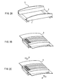
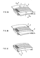
- Figs. 2A to 2C and Figs. 3A to 3C are perspective views showing a process of welding a color selecting electrode to a frame, which is conducted in the order presented.
- the shadow mask is welded to two opposite sides of the frame, only to long sides in the present case.
- Fig. 1A illustrates an outline of a frame 3 made up of long frame sides 1 and short frame sides 2 as viewed from a top face thereof.
- Fig. 1B is a side view of the frame 3.
- I to VII denote each step number of the welding route for welding the shadow mask to the frame 3, where a welding head moves from step I in ascending order.
- the color selecting electrode is welded while applying a load to the long frame sides 1 in a direction to make the long frame sides 1 curve toward the inside.
- the welding head moves down onto one end portion of the long frame side 1 (Step I), welding is conducted from the end portion toward a center portion of the long frame side 1 (Step II). Then, after moving up once (Step III), the welding head moves horizontally toward the other end portion of the long frame side 1 (Step IV) and moves down onto the long frame side 1 (Step V), and welding is conducted from the other end portion toward a center portion of the long frame side 1 (Step VI). Finally, the welding head retracts (Step VII). In this way, a starting point of the welding route is located at an end portion of the long frame side 1, and a termination of the welding route is located at a center portion of the long frame side 1.
- the welding route is set so that a welded portion in Step II and a welded portion in Step VI partially overlap each other, e.g., a terminal portion in Step II and a terminal portion in Step VI overlap approximately 1 mm in the direction along the welding route. This ensures that welding is conducted over the entire side.
- a frame 3 made up of long frame sides 1 and short frame sides 2 is prepared (Fig. 2A).
- a mask plate 5 to be processed as a shadow mask 4 (See Fig. 3C), namely a color selecting electrode provided with rectangular mask apertures, is mounted (Fig. 2B).
- a tensile force 6 in a direction parallel to the short frame side 2 is applied to the mask plate 5 (Fig. 2C).
- a desired compressive force 7 is applied to opposite long frame sides 1 of the frame 3 so as to deform the frame 3 (Fig. 3A).
- the compressive force 7 is set so that the amount of compressive deformation is greater at a center portion than end portions of the long frame sides 1. For instance, in the case where the shape of the frame 3 before being applied the compressive force 7 is rectangular, then the compressive force 7 is applied so that the shape of the frame 3 is deformed into an hourglass shape.
- the mask plate 5 and the long frame sides 1 are welded and bonded by means of a welding roller 8 (Fig. 3B).
- the welding is conducted along the welding route described referring to Figs. 1A and 1B.
- the welding is conducted with a resistance welding method, where the welding roller 8 functions as an electrode in the resistance welding method.
- the welding in the present invention can be conducted with methods other than the resistance welding method.
- a shadow mask structure color selecting electrode structure
- a desired tensile force is applied to the shadow mask 4 in the direction parallel to the short side and a tensile distribution becomes such that a tensile force acting at the center portion of the long side direction of the shadow mask 4 is larger than a tensile force acting at the end portions thereof.
- this embodiment deals with the case where the welding is conducted while applying the tensile force 6 and the compressive force 7 to the mask plate 5 and the long frame sides 1, respectively, the welding may be conducted while applying any one of the tensile force 6 and the compressive force 7.
- a cathode ray tube can be completed using a normal manufacturing method for the other processes.
- the welding starts from an end portion of each of the two sides and terminates at a center portion of each of the two sides, whereby thegeneration of wrinkles in the shadow mask can be suppressed. Accordingly, a deterioration of a picture quality of the cathode ray tube, such as color displacement in the image, can be avoided.
- the wrinkles could be positioned at a center portion in the long side direction where a deflection angle of an electron beam is small. Consequently, compared with the case where wrinkles were generated in the vicinity of the end portions in the long side direction of the frame 3 where a deflection angle of an electron beam is large, the shifting amount of a position of an aperture in the shadow mask along the deflection direction of the electron beam, generated due to the wrinkles, could be reduced, thus suppressing the shifting in the landing position of the electron beam. Thereby, factors that deteriorate a picture quality, such as color displacement in an image of the cathode ray tube, can be reduced.
- a distortion generated in the shadow mask 4 can be lessened by such a larger tensile force. This can suppress the shifting in the landing position of the electron beam due to the wrinkles in the shadow mask 4 and therefore can reduce factors that deteriorate a picture quality, such as color displacement in an image of the cathode ray tube.
- the wrinkle grade As for the wrinkle grade, the grade 5 is entirely satisfactory, the grades 2 or less indicate defectives in terms of actual products, and the grades between 3 and 5 indicate conforming items. The significance of these wrinkle grades was confirmed by determining conforming items and defectives of the shadow masks, based on the results of estimating picture qualities of cathode ray tubes that were produced separately using the shadow masks that have been ranked as each wrinkle grade.
- Fig. 4 shows the results obtained by using the welding method of the present invention
- Fig. 5 shows the results obtained by using the conventional welding method.
- the number of test samples was 10 in each case.
- one of ten samples was a wrinkle defective, so that the percentage of wrinkle defectives was 10%
- eight of ten samples were wrinkle defectives, so that the percentage of wrinkle defectives was 80%.
- the percentage of wrinkle defectives could be improved considerably.
- Fig. 6 shows the results confirming the effectiveness of the welding method of the present invention, by increasing the number of test samples. 646 shadow mask structures were produced on an experimental basis, and wrinkles generated in these shadow masks were estimated. As a result, the number of wrinkle defectives with a wrinkle grade of 2 or less was 11, so that the percentage of wrinkle defectives was 1.7%. Accordingly, it can be found that the welding method of the present invention can realize a significantly low defective percentage.
- the present invention is applicable to the case where the shape of the frame 3 before being subjected to the compressive force is a shape where a distance between opposite long frame sides 1 is longer at a center portion than at end portions, or conversely a shape where the distance between opposite long frame sides 1 is shorter at a center portion than at end portions.
- the present invention is applicable to the case where the color selecting electrode is welded to a pair of short frame sides.
Landscapes
- Engineering & Computer Science (AREA)
- Manufacturing & Machinery (AREA)
- Electrodes For Cathode-Ray Tubes (AREA)
Abstract
A welding route of welding a color selecting electrode to a frame is as
follows: first of all, a welding head moves down onto one end portion of a
long frame side (Step I), welding is conducted from the end portion toward a
center portion of the long frame side (Step II). Then, after moving up once
(Step III), the welding head moves horizontally toward the other end portion
of the long frame side (Step IV) and moves down onto the long frame side
(Step V), and welding is conducted from the other end portion toward a
center portion of the long frame side (Step VI). Finally, the welding head
retracts (Step VII). With this welding route, the generation of wrinkles in
the vicinity of the end portions of the long sides of the color selecting
electrode can be suppressed.
Description
The present invention relates to a method of manufacturing a
cathode ray tube for use in a television set, a computer display and the like.
Conventionally, as a method of manufacturing a color selection
mechanism for use in cathode ray tubes, JP 7(1995)-211229 A, for example,
describes a method of welding a color selecting electrode to a frame, where
the color selecting electrode includes an aperture grill provided with a
plurality of parallel and vertical slits formed in a metal sheet. Figs. 7A and
7B show a welding route during the welding process.
The color selecting electrode including the aperture grill is welded
only to long frame sides 1 of a frame 3 made up of the long frame sides 1 and
short frame sides 2. The welding route includes the following steps as
shown in Figs. 7A and 7B: a welding head moves down onto a center portion
of the long frame side 1 (Step I), welding is conducted from the center
portion toward one end of the long frame side 1 (Step II) followed by a step
where the welding head moves up once (Step III), the welding head moves
horizontally toward a center portion of the long frame side 1 (Step IV)
followed by a step where the welding head moves down onto the long frame
side 1 (Step V), welding is conducted from the center portion toward the
other end of the long frame side 1 (Step VI), and the welding head retracts
(Step VII) so as to complete the welding of the color selecting electrode to
the frame 3.
However, in the case of applying this welding method to a
tension-type shadow mask as described in JP 2000-77007 A where a tensile
force parallel to a short side direction of a frame is applied to a shadow
mask (color selecting electrode) and a tensile distribution is required for a
long side direction of the frame so that a tensile force at a center portion is
larger than a tensile force at an end portion, the following problem would
occur: that is, the welding of the color selecting electrode to the frame with
the conventional welding method described in JP 7-211229 A causes the
concentration of a distortion in the color selecting electrode, which is
generated due to welding heat, at a termination part of the welding route.
Therefore so-called wrinkles are generated in the vicinity of the end portions
of the long side direction of the color selecting electrode, which correspond to
the termination of the welding route, thus deteriorating a picture quality of
the cathode ray tube.
In view of the above-stated problem, it is an object of the present
invention to provide a cathode ray tube manufacturing method, which can
suppress the generation of wrinkles in a color selecting electrode. More
particularly, it is an object of the present invention to provide a cathode ray
tube manufacturing method, which can suppress the generation of wrinkles
in the vicinity of end portions of long side direction of a color selecting
electrode in a cathode ray tube in which a desired tensile force is applied to
the color selecting electrode and a tensile distribution is required for a long
side direction so that a tensile force at a center portion is larger than a
tensile force at an end portion.
To fulfill the above-stated object, a cathode ray tube manufacturing
method according to the present invention includes the step of welding a
color selecting electrode to two opposite sides of a frame along a
predetermined welding route. In this method, a termination of the welding
route is located at a center portion of each of the two sides. With this
method, when welding the color selecting electrode to the frame, the
generation of wrinkles in the color selecting electrode can be suppressed,
thus preventing a deterioration of a picture quality of the cathode ray tube,
such as color displacement in the image. Even when wrinkles were
generated in the color selecting electrode, the wrinkles could be positioned
at a center portion of the side of the frame where a deflection angle of an
electron beam is small. Consequently, compared with the case where
wrinkles were generated in the vicinity of the end portions of the side of the
frame where a deflection angle of an electron beam is large, the shifting
amount of a position of an aperture in the color selecting electrode along the
deflection direction of the electron beam, generated due to the wrinkles,
could be reduced, thus suppressing the shifting in the landing position of the
electron beam. Thereby, factors that deteriorate a picture quality, such as
color displacement in an image, can be reduced.
In addition, since the termination of the welding route for welding
the color selecting electrode to the frame is located at a center portion of the
side to be welded, a distortion generated in a color selecting electrode, to
which a tensile force is applied so as to become the largest at the center
portion of the side, can be lessened by such a tensile force. This can
suppress the shifting in the landing position of the electron beam and
therefore can reduce factors that deteriorate a picture quality, such as color
displacement in an image.
The following describes one embodiment of the present invention,
with reference to the drawings.
Figs. 1A and 1B show a welding route of welding a shadow mask
(color selecting electrode) to a frame according to a cathode ray tube
manufacturing method of the present invention. Figs. 2A to 2C and Figs.
3A to 3C are perspective views showing a process of welding a color selecting
electrode to a frame, which is conducted in the order presented. The
shadow mask is welded to two opposite sides of the frame, only to long sides
in the present case.
Fig. 1A illustrates an outline of a frame 3 made up of long frame
sides 1 and short frame sides 2 as viewed from a top face thereof. Fig. 1B is
a side view of the frame 3. I to VII denote each step number of the welding
route for welding the shadow mask to the frame 3, where a welding head
moves from step I in ascending order. The color selecting electrode is
welded while applying a load to the long frame sides 1 in a direction to make
the long frame sides 1 curve toward the inside.
When welding the shadow mask to the frame 3, as shown in Figs. 1A
and 1B, first of all, the welding head moves down onto one end portion of the
long frame side 1 (Step I), welding is conducted from the end portion toward
a center portion of the long frame side 1 (Step II). Then, after moving up
once (Step III), the welding head moves horizontally toward the other end
portion of the long frame side 1 (Step IV) and moves down onto the long
frame side 1 (Step V), and welding is conducted from the other end portion
toward a center portion of the long frame side 1 (Step VI). Finally, the
welding head retracts (Step VII). In this way, a starting point of the
welding route is located at an end portion of the long frame side 1, and a
termination of the welding route is located at a center portion of the long
frame side 1.
Note here that the welding route is set so that a welded portion in
Step II and a welded portion in Step VI partially overlap each other, e.g., a
terminal portion in Step II and a terminal portion in Step VI overlap
approximately 1 mm in the direction along the welding route. This ensures
that welding is conducted over the entire side.
A process of welding the shadow mask will be described in the
following, referring to Figs. 2A to 2C and Figs. 3A to 3C. First of all, a
frame 3 made up of long frame sides 1 and short frame sides 2 is prepared
(Fig. 2A). On the frame 3, a mask plate 5 to be processed as a shadow
mask 4 (See Fig. 3C), namely a color selecting electrode provided with
rectangular mask apertures, is mounted (Fig. 2B). In order to remove the
waviness in the shadow mask 4 under tension and to apply a desired tensile
force to the shadow mask 4, a tensile force 6 in a direction parallel to the
short frame side 2 is applied to the mask plate 5 (Fig. 2C).
Next, while applying the tensile force 6 to the mask plate 5, a
desired compressive force 7 is applied to opposite long frame sides 1 of the
frame 3 so as to deform the frame 3 (Fig. 3A). The compressive force 7 is
set so that the amount of compressive deformation is greater at a center
portion than end portions of the long frame sides 1. For instance, in the
case where the shape of the frame 3 before being applied the compressive
force 7 is rectangular, then the compressive force 7 is applied so that the
shape of the frame 3 is deformed into an hourglass shape.
In this way, while applying the tensile force 6 and the compressive
force 7 to the mask plate 5 and the long frame sides 1, respectively, the
mask plate 5 and the long frame sides 1 are welded and bonded by means of
a welding roller 8 (Fig. 3B). In this step, the welding is conducted along
the welding route described referring to Figs. 1A and 1B. In this
embodiment, the welding is conducted with a resistance welding method,
where the welding roller 8 functions as an electrode in the resistance
welding method. However, naturally, the welding in the present invention
can be conducted with methods other than the resistance welding method.
Subsequently, the tensile force 6 and the compressive force 7 are
released and unnecessary portions of the mask plate 5 are trimmed, so that
a shadow mask structure (color selecting electrode structure) configured
with the shadow mask 4 welded to the frame 3 can be obtained (Fig. 3C).
By the tensile force 6 that was applied to the mask plate 5 and a restoring
force of the long frame sides 1 deformed by the compressive force 7, a
desired tensile force is applied to the shadow mask 4 in the direction
parallel to the short side and a tensile distribution becomes such that a
tensile force acting at the center portion of the long side direction of the
shadow mask 4 is larger than a tensile force acting at the end portions
thereof. Note here that although this embodiment deals with the case
where the welding is conducted while applying the tensile force 6 and the
compressive force 7 to the mask plate 5 and the long frame sides 1,
respectively, the welding may be conducted while applying any one of the
tensile force 6 and the compressive force 7.
Using the thus obtained shadow mask structure, a cathode ray tube
can be completed using a normal manufacturing method for the other
processes.
As stated above, when welding the shadow mask 4 to two opposite
sides (long frame sides 1) of the frame 3, the welding starts from an end
portion of each of the two sides and terminates at a center portion of each of
the two sides, whereby thegeneration of wrinkles in the shadow mask can
be suppressed. Accordingly, a deterioration of a picture quality of the
cathode ray tube, such as color displacement in the image, can be avoided.
In addition, even when wrinkles were generated in the shadow mask
4 because the thermal expansion due to welding heat is larger in the shadow
mask 4 than in the frame 3, the wrinkles could be positioned at a center
portion in the long side direction where a deflection angle of an electron
beam is small. Consequently, compared with the case where wrinkles were
generated in the vicinity of the end portions in the long side direction of the
frame 3 where a deflection angle of an electron beam is large, the shifting
amount of a position of an aperture in the shadow mask along the deflection
direction of the electron beam, generated due to the wrinkles, could be
reduced, thus suppressing the shifting in the landing position of the electron
beam. Thereby, factors that deteriorate a picture quality, such as color
displacement in an image of the cathode ray tube, can be reduced.
Furthermore, by terminating the welding route at the center portion
in the long side direction of the shadow mask 4, on which a larger tensile
force acts, a distortion generated in the shadow mask 4 can be lessened by
such a larger tensile force. This can suppress the shifting in the landing
position of the electron beam due to the wrinkles in the shadow mask 4 and
therefore can reduce factors that deteriorate a picture quality, such as color
displacement in an image of the cathode ray tube.
Next, the following describes the results of experiments to confirm
these effects. After subjecting shadow mask structures obtained by using
the welding method of the present invention described referring to Figs. 1A
and 1B, Figs. 2A to 2C and Figs. 3A to 3C and shadow mask structures
obtained by using the conventional welding method shown in Figs. 7A and
7B to a heat treatment, wrinkles generated in the shadow masks included in
these shadow mask structures were measured. The measurement results
will be shown in Figs. 4 to 6. The horizontal axis of each of these drawings
indicates grades of estimated wrinkles (hereinafter called "wrinkle grade"),
and the vertical axis indicates frequency of each wrinkle grade. As for the
wrinkle grade, the grade 5 is entirely satisfactory, the grades 2 or less
indicate defectives in terms of actual products, and the grades between 3
and 5 indicate conforming items. The significance of these wrinkle grades
was confirmed by determining conforming items and defectives of the
shadow masks, based on the results of estimating picture qualities of
cathode ray tubes that were produced separately using the shadow masks
that have been ranked as each wrinkle grade.
Fig. 4 shows the results obtained by using the welding method of the
present invention, and Fig. 5 shows the results obtained by using the
conventional welding method. The number of test samples was 10 in each
case. As is evident from Figs. 4 and 5, according to the welding method of
the present invention, one of ten samples was a wrinkle defective, so that
the percentage of wrinkle defectives was 10%, while according to the
conventional welding method, eight of ten samples were wrinkle defectives,
so that the percentage of wrinkle defectives was 80%. Thus, according to
the welding method of the present invention, the percentage of wrinkle
defectives could be improved considerably.
Fig. 6 shows the results confirming the effectiveness of the welding
method of the present invention, by increasing the number of test samples.
646 shadow mask structures were produced on an experimental basis, and
wrinkles generated in these shadow masks were estimated. As a result,
the number of wrinkle defectives with a wrinkle grade of 2 or less was 11, so
that the percentage of wrinkle defectives was 1.7%. Accordingly, it can be
found that the welding method of the present invention can realize a
significantly low defective percentage.
Note here that although the above-described embodiment deals with
the case where the shape of the frame 3 before being subjected to the
compressive force is rectangular, the present invention is applicable to the
case where the shape of the frame 3 before being subjected to the
compressive force is a shape where a distance between opposite long frame
sides 1 is longer at a center portion than at end portions, or conversely a
shape where the distance between opposite long frame sides 1 is shorter at a
center portion than at end portions.
Additionally, although the above-described embodiment deals with
the case where the color selecting electrode is welded to a pair of long frame
sides, the present invention is applicable to the case where the color
selecting electrode is welded to a pair of short frame sides.
The invention may be embodied in other forms without departing
from the spirit or essential characteristics thereof. The embodiments
disclosed in this application are to be considered in all respects as
illustrative and not limiting. The scope of the invention is indicated by the
appended claims rather than by the foregoing description, and all changes
which come within the meaning and range of equivalency of the claims are
intended to be embraced therein.
Claims (3)
- A method of manufacturing a cathode ray tube, comprising the step of welding a color selecting electrode to two opposite sides of a frame along a predetermined welding route, wherein a termination of the welding route is located at a center portion of each of the two sides.
- The method of manufacturing a cathode ray tube according to claim 1, wherein a starting point of the welding route is located at an end portion of each of the two sides.
- The method of manufacturing a cathode ray tube according to claim 1, wherein the color selecting electrode is welded to the frame in such a manner that a tensile force acting on the color selecting electrode after welding to the frame is larger at a center portion than at end portions of each of the sides.
Applications Claiming Priority (3)
| Application Number | Priority Date | Filing Date | Title |
|---|---|---|---|
| JP2001115041A JP3876639B2 (en) | 2001-04-13 | 2001-04-13 | Method for manufacturing cathode ray tube |
| JP2001115041 | 2001-04-13 | ||
| PCT/JP2002/003565 WO2002084690A1 (en) | 2001-04-13 | 2002-04-10 | Production method of cathode ray tube |
Publications (2)
| Publication Number | Publication Date |
|---|---|
| EP1302970A1 true EP1302970A1 (en) | 2003-04-16 |
| EP1302970A4 EP1302970A4 (en) | 2005-11-23 |
Family
ID=18966004
Family Applications (1)
| Application Number | Title | Priority Date | Filing Date |
|---|---|---|---|
| EP02717092A Withdrawn EP1302970A4 (en) | 2001-04-13 | 2002-04-10 | PROCESS FOR PRODUCING CATHODE RAY TUBE |
Country Status (6)
| Country | Link |
|---|---|
| US (1) | US6857927B2 (en) |
| EP (1) | EP1302970A4 (en) |
| JP (1) | JP3876639B2 (en) |
| KR (1) | KR100510024B1 (en) |
| CN (1) | CN1231943C (en) |
| WO (1) | WO2002084690A1 (en) |
Family Cites Families (7)
| Publication number | Priority date | Publication date | Assignee | Title |
|---|---|---|---|---|
| JPH0687394B2 (en) * | 1986-04-01 | 1994-11-02 | ソニー株式会社 | Machine for making color selective electrode of cathode ray tube |
| US4828523A (en) * | 1987-06-04 | 1989-05-09 | Zenith Electronics Corporation | Tension mask securement means and process therefore |
| US4834686A (en) * | 1987-12-29 | 1989-05-30 | Zenith Electronics Corporation | Rail mapping method and apparatus |
| US4828524A (en) * | 1987-12-31 | 1989-05-09 | Zenith Electronics Corporation | Rail mapping method and apparatus |
| JPH07211229A (en) | 1994-01-13 | 1995-08-11 | Sony Corp | Welding method of flat aperture grill and flat aperture grill mount |
| JP2000067748A (en) * | 1998-08-26 | 2000-03-03 | Matsushita Electronics Industry Corp | Manufacture of color cathode-ray tube |
| JP3300669B2 (en) | 1998-09-01 | 2002-07-08 | 松下電器産業株式会社 | Color cathode ray tube |
-
2001
- 2001-04-13 JP JP2001115041A patent/JP3876639B2/en not_active Expired - Fee Related
-
2002
- 2002-04-10 US US10/311,028 patent/US6857927B2/en not_active Expired - Fee Related
- 2002-04-10 KR KR10-2002-7016879A patent/KR100510024B1/en not_active Expired - Fee Related
- 2002-04-10 CN CNB028011988A patent/CN1231943C/en not_active Expired - Fee Related
- 2002-04-10 EP EP02717092A patent/EP1302970A4/en not_active Withdrawn
- 2002-04-10 WO PCT/JP2002/003565 patent/WO2002084690A1/en not_active Ceased
Also Published As
| Publication number | Publication date |
|---|---|
| EP1302970A4 (en) | 2005-11-23 |
| KR100510024B1 (en) | 2005-08-24 |
| CN1231943C (en) | 2005-12-14 |
| WO2002084690A1 (en) | 2002-10-24 |
| JP2002313227A (en) | 2002-10-25 |
| US20030171061A1 (en) | 2003-09-11 |
| KR20030007954A (en) | 2003-01-23 |
| CN1461491A (en) | 2003-12-10 |
| US6857927B2 (en) | 2005-02-22 |
| JP3876639B2 (en) | 2007-02-07 |
Similar Documents
| Publication | Publication Date | Title |
|---|---|---|
| US6890237B2 (en) | Shadow mask assembly manufacturing method and cathode ray tube manufacturing method | |
| US6857927B2 (en) | Method of securing shadow mask and frame in the manufacture of a cathode ray tube | |
| JPH09161672A (en) | Assembling method of color selection mechanism for cathode ray tube | |
| US6781297B2 (en) | Method and apparatus for maintaining mask strand spatial uniformity | |
| US6285120B1 (en) | Shadow mask of cathode ray tube and manufacturing method thereof | |
| EP0881659A2 (en) | Color cathode-ray tube | |
| JP3468689B2 (en) | Shadow mask and color picture tube | |
| JP2683674B2 (en) | Cathode ray tube color selection mechanism | |
| JP2770355B2 (en) | Manufacturing method of color CRT | |
| KR200251702Y1 (en) | Shadow Mask Assembly for Cathode Ray Tube | |
| US7227298B2 (en) | Color picture tube and method for manufacturing the same | |
| JP3644754B2 (en) | Color picture tube | |
| JP2003346678A (en) | Color cathode ray tube and method of manufacturing the same | |
| JP2003031119A (en) | Manufacturing method of color cathode ray tube | |
| JP2004022509A (en) | CRT and color selection mechanism | |
| JPH11204055A (en) | Color selection mechanism for color cathode ray tube and method of manufacturing the same | |
| JP2002319352A (en) | Color cathode ray tube | |
| JP2003109500A (en) | Manufacturing method of color cathode ray tube | |
| JPH10125249A (en) | Electrode device for color selection of cathode ray tube | |
| JP2002304953A (en) | Color cathode ray tube and method of manufacturing the same | |
| JPH10306349A (en) | Low thermal expansion alloy sheet with excellent etching properties for electronic components | |
| JPH10199406A (en) | Manufacturing method of color selection electrode | |
| JP2002289110A (en) | Aperture grill and color selection mechanism with the same | |
| JP2003016932A (en) | Manufacturing method of cathode ray tube | |
| JPH09125206A (en) | Low thermal expansion alloy sheet for electronic parts with excellent etching properties |
Legal Events
| Date | Code | Title | Description |
|---|---|---|---|
| PUAI | Public reference made under article 153(3) epc to a published international application that has entered the european phase |
Free format text: ORIGINAL CODE: 0009012 |
|
| 17P | Request for examination filed |
Effective date: 20021220 |
|
| AK | Designated contracting states |
Designated state(s): AT BE CH CY DE DK ES FI FR GB GR IE IT LI LU MC NL PT SE TR |
|
| A4 | Supplementary search report drawn up and despatched |
Effective date: 20051007 |
|
| STAA | Information on the status of an ep patent application or granted ep patent |
Free format text: STATUS: THE APPLICATION IS DEEMED TO BE WITHDRAWN |
|
| 18D | Application deemed to be withdrawn |
Effective date: 20051222 |