EP1302829B1 - Numerical controller - Google Patents
Numerical controller Download PDFInfo
- Publication number
- EP1302829B1 EP1302829B1 EP02257109A EP02257109A EP1302829B1 EP 1302829 B1 EP1302829 B1 EP 1302829B1 EP 02257109 A EP02257109 A EP 02257109A EP 02257109 A EP02257109 A EP 02257109A EP 1302829 B1 EP1302829 B1 EP 1302829B1
- Authority
- EP
- European Patent Office
- Prior art keywords
- tool
- motion
- axis
- coordinate system
- axes
- Prior art date
- Legal status (The legal status is an assumption and is not a legal conclusion. Google has not performed a legal analysis and makes no representation as to the accuracy of the status listed.)
- Expired - Fee Related
Links
Images


Classifications
-
- G—PHYSICS
- G05—CONTROLLING; REGULATING
- G05B—CONTROL OR REGULATING SYSTEMS IN GENERAL; FUNCTIONAL ELEMENTS OF SUCH SYSTEMS; MONITORING OR TESTING ARRANGEMENTS FOR SUCH SYSTEMS OR ELEMENTS
- G05B19/00—Programme-control systems
- G05B19/02—Programme-control systems electric
- G05B19/18—Numerical control [NC], i.e. automatically operating machines, in particular machine tools, e.g. in a manufacturing environment, so as to execute positioning, movement or co-ordinated operations by means of programme data in numerical form
- G05B19/41—Numerical control [NC], i.e. automatically operating machines, in particular machine tools, e.g. in a manufacturing environment, so as to execute positioning, movement or co-ordinated operations by means of programme data in numerical form characterised by interpolation, e.g. the computation of intermediate points between programmed end points to define the path to be followed and the rate of travel along that path
-
- G—PHYSICS
- G05—CONTROLLING; REGULATING
- G05B—CONTROL OR REGULATING SYSTEMS IN GENERAL; FUNCTIONAL ELEMENTS OF SUCH SYSTEMS; MONITORING OR TESTING ARRANGEMENTS FOR SUCH SYSTEMS OR ELEMENTS
- G05B2219/00—Program-control systems
- G05B2219/30—Nc systems
- G05B2219/50—Machine tool, machine tool null till machine tool work handling
- G05B2219/50297—Compensation of positioning error due to a-axis, b-axis tool rotation
-
- Y—GENERAL TAGGING OF NEW TECHNOLOGICAL DEVELOPMENTS; GENERAL TAGGING OF CROSS-SECTIONAL TECHNOLOGIES SPANNING OVER SEVERAL SECTIONS OF THE IPC; TECHNICAL SUBJECTS COVERED BY FORMER USPC CROSS-REFERENCE ART COLLECTIONS [XRACs] AND DIGESTS
- Y10—TECHNICAL SUBJECTS COVERED BY FORMER USPC
- Y10T—TECHNICAL SUBJECTS COVERED BY FORMER US CLASSIFICATION
- Y10T409/00—Gear cutting, milling, or planing
- Y10T409/30—Milling
- Y10T409/30084—Milling with regulation of operation by templet, card, or other replaceable information supply
- Y10T409/300896—Milling with regulation of operation by templet, card, or other replaceable information supply with sensing of numerical information and regulation without mechanical connection between sensing means and regulated means [i.e., numerical control]
-
- Y—GENERAL TAGGING OF NEW TECHNOLOGICAL DEVELOPMENTS; GENERAL TAGGING OF CROSS-SECTIONAL TECHNOLOGIES SPANNING OVER SEVERAL SECTIONS OF THE IPC; TECHNICAL SUBJECTS COVERED BY FORMER USPC CROSS-REFERENCE ART COLLECTIONS [XRACs] AND DIGESTS
- Y10—TECHNICAL SUBJECTS COVERED BY FORMER USPC
- Y10T—TECHNICAL SUBJECTS COVERED BY FORMER US CLASSIFICATION
- Y10T409/00—Gear cutting, milling, or planing
- Y10T409/30—Milling
- Y10T409/306664—Milling including means to infeed rotary cutter toward work
Definitions
- the present invention relates to a numerical controller for controlling a machine having an axis for turning a table or a workpiece holding stock on which a workpiece is mounted.
- a machine tool having a plurality of linear motion axes and an axis for turning a table for mounting a workpiece, and further having an axis for tilting a tool head or the table.
- a table 1 is arranged movable in directions of rectangular axes of X, Y and a tool head 2 is arranged movable in a direction of a Z-axis perpendicular to the X- and Y-axes, the table 1 is turned around a C-axis parallel to the Z-axis and further the tool head 2 is arranged to tilt around an A-axis parallel to the X-axis.
- a workpiece 3 mounted on the table 1 is machined by a tool of the tool head 2 by driving the five axes.
- a tool head 2 is arranged movable in directions of three rectangular axes of X, Y, Z and the table 1 is arranged to turn around a C-axis on the Y-Z-plane and further tilt around an A-axis parallel to the X-axis, to machine a workpiece 3 mounted on the table 1 by a tool of the tool head 2.
- Co presents a center of turning of the table 3
- CS represents a reference position of angular position of the C-axis
- the table 3 is turned so that a commanded angular position of the C-axis is moved to the reference position CS.
- a controlled point P of the tool head 2 is set at a center of turning of the tool.
- FIG. 5a shows a state in which the tool 2 is positioned at a commanded position by the first block "N200", i.e. X coordinate value of Xc0, Y coordinate value of Yc0, Z coordinate value of Zc0, A-axis angle of 60 degree and C-axis angle of 30 degree, which is a machining start position of the second block "N 301".
- FIG. 5b shows a state in which the tool is positioned at a commanded position by the second block "N301", i.e.
- FIG. 5c shows a state in which the tool is positioned at an end point of the third block "N 302" to terminate the machining along the straight line L.
- FIG. 4 is depicted with the C-axis stationary and the tool head 2 moved along the C-axis, and actually the C-axis is moved and the tool head as shown in FIG. 5 .
- FIG. 4 as viewed in the direction of Z-axis.
- the above example is directed to the machine tool having the C-axis for turning the table 1 and the A-axis for tilting the tool head 1 in addition to the linear-motion axes.
- the machine tool may have two axes for turning and for tilting the table 1 in addition to the linear-motion axes.
- Document JP 60- 230 207 and document EP-A-0 271 691 show a numerical controller for a robot having an axis for turning a table and a plurality of axes for moving the arm, whereby the work piece mounted on the table is processed by driving all axes.
- An object of the present invention is to provide a numerical controller capable of precisely controlling a machine tool having an axis for turning a table with a simple machining program and easily coping with variation of a tool length.
- a numerical controller of the present invention is defined in attached claim 1. Preferred embodiments are defined in dependent claims 2 to 9.
- a principle of the present invention will be described with respect to a machine tool having two rotational motion axes of a C-axis for turning a table and an A-axis for tilting a tool head in addition to linear motion axes of X, Y and Z, as shown in FIG. 6 .
- the principle is applicable to a machine tool having rotational-motion axes other than the A-axis and C-axis as shown in FIG. 6 and a machine tool having two axes for turning and tilting the table.
- a tool center point Tp representing a position of a tool is set at a tip of the tool.
- a workpiece coordinate system ⁇ W is defined by setting a position (Xw, Yw, Zw) of an origin thereof in a machine coordinate system ⁇ M.
- a controlled point P is set at a center of swinging motion of the tool head and a distance between the controlled point P and the tool center point Tp is stored as a tool length compensation amount H.
- a position (Xs, Ys, Zs) of the tool center point Tp at a start of machining in the workpiece coordinate system ⁇ W is obtained according to the following equations (1)-(3) based on a position (Xm, Ym, Zm) of the controlled point P at the start of machining in the machine coordinate system ⁇ M, an orientation of the tool (Am, Cm) and the tool length compensation amount H. Since the orientation of the tool is defined relatively to a workpiece on the table, the orientation of the tool is determined by an angle Am of rotation of the A-axis for tiling the tool and an angle Cm of rotation of the C-axis for turning the table 1 (workpiece 3). Angular positions (As, Cs) of the rotational-motion axes at the start of machining is defined as angular positions (Am, Cm) in the machine coordinate system ⁇ M.
- the position (Xm, Ym, Zm, Am, Cm) of the controlled point P including the angular positions of the rotational-motion axes at the start of machining in the machine coordinate system ⁇ M is stored as a position (Xo, Yo, Zo, Ao, Co) of the controlled point P at the preceding interpolation period for interpolating processing as described later, and the position (Xs, Ys, Zs) of the tool center point Tp at the start of machining in the workpiece coordinate system ⁇ W is stored as a position (Xj, Yj, Zj) of the tool center point Tp at the preceding interpolation period.
- the angular position Cm of the C-axis at the start of machining is stored as Cz.
- the coordinate value (Xr, Yr, Zr) of a center of turning of the table in the machine coordinate system ⁇ M is stored.
- the tool center point control may be started by shifting the position (Xm, Ym, Zm) of the controlled point P of the linear-motion axes in the machine coordinate system ⁇ M to be positioned at the tool center point Tp in the workpiece coordinate system at the start of machining.
- a tool length compensation vector V(Vx, Vy, Vz) is obtained using the orientation of the tool (Am, Cm) and the tool compensation amount H according to the following equations (4)-(6).
- Vx 0
- Vy H * cos Am
- Vz H * sin Am
- the position (Xw, Yw, Zw) of the origin of the workpiece coordinate system ⁇ W is subtracted from the position (Xm, Ym, Zm) of the controlled point P in the machine coordinate system ⁇ M when the coordinate values of the X, Y and Z axes are shifted by the vector V, to obtain the position (Xs, Ys, Zs) of the tool center position at the start of machining in the workpiece coordinate system ⁇ W, according to the following equations. (7)-(9)
- commands in the machining program are regarded as commands in the workpiece coordinate system ⁇ W (the commands are prepared as commands in the workpiece coordinate system ⁇ W) and interpolation processing is performed based on a velocity F commanded in the workpiece coordinate system ⁇ W.
- An interpolated position (Xc, Yc, Zc Ac, Cc) of the controlled point P in the machine coordinate system ⁇ M is obtained at every interpolation period At as follows;
- a length of the block from the start position (Xs, Ys, Zs) to the end position (Xe, Ye, Ze) is obtained by the following equation (11).
- D ⁇ ⁇ ( Xe - Xs ⁇ ) 2 - ( Ye - Ys ⁇ ) 2 + ( Ze - Zs ⁇ ) 2
- Interpolations for the rotational-motion axes of the A-axis and the C-axis are performed from a start position (As, Cs) to the end position (Ae, Ce) to obtain an interpolation point (Ai, Ci).
- the position of the interpolation point (Ai, Ci) is distributed proportionally at the same rate as that of distribution of the interpolation of movement of the tool center point Tp from the start position (Xs, Ys, Zs) to the end position (Xe, Ye, Ze).
- K ⁇ 2 ⁇ ( Xi - Xs ⁇ ) 2 + ( Yi - Ys ⁇ ) 2 + ( Zi - Zs ⁇ ) 2 / [ ⁇ ( Xe - Xs ⁇ ) 2 + ( Ye - Ys ⁇ ) 2 + ( Ze - Zs ⁇ ) 2 ] the interpolated position of the A-axis and the C-axis are obtained according to the following equations (16)-(17).
- the interpolation point (Xi, Yi, Zi) of the tool center point Tp for the linear-motion axes in the workpiece coordinate system ⁇ W is corrected by the turning angle of the table and transformed at every interpolation processing period, to obtain a coordinate position (Xa, Ya, Za) of the tool center point Tp in the machine coordinate system ⁇ M according to the following equations (18)-(20).
- the tool length compensation vector V(Vx, Vy, Vz) is calculated using the interpolated position (Ai) of the A-axis and the tool length compensation mount H according to the following equations (21)-(23) at every interpolation processing period.
- Vx 0
- Vy H * cos Ai
- Vz H * sin Ai
- a difference between the interpolated position (Xc, Yc, Zc) of the controlled point P in the present interpolation period and the interpolated position (Xo, Yo, Zo) of the controlled point P in the preceding processing period is outputted to the servo systems for the linear axes of X, Y, Z as motion amounts. Also, differences between the interpolated positions (Ac, Cc) of the rotational-motion axes and the interpolated positions (Ao, Co) in the preceding interpolation period are outputted to the servo systems of the rotational-motion axes of A and C, respectively.
- the interpolated position (Xc, Yc, Zc) of the controlled point P are stored as the preceding interpolated position (Xo, Yo, Zo) and the interpolated angular positions (Ac, Cc) of the rotational-motion axes are stored as the preceding interpolated positions (Ao, Co) for use in the interpolation processing in the next processing period.
- the workpiece coordinate system is not considered with respect to A- and C- axes for simplification.
- the calculations may be performed by taking the workpiece coordinate system into consideration with respect to the A- and C- axes in the same manner as the X-, Y- and Z- axes.
- the workpiece coordinate system ⁇ W is set to the table 1 at a start of the tool center point control, and commands of the machining program are executed in the workpiece coordinate system ⁇ W. Since the workpiece coordinate system ⁇ W turns with the turn table 1, a relationship between a machining path of the tool center point P commanded by the machining program for determining a shape of the machining in the workpiece coordinate system ⁇ W and an actual machining path on the workpiece 3 mounted on the table 1 is fixed. Thus, the machining shape on the workpiece defined in the workpiece coordinate system ⁇ W is realized on the workpiece 3.
- the commands of the machining program may be prepared as commands in a stationary workpiece coordinate system. Specifically, it is possible to prepare the commands of the machining program in the stationary workpiece coordinate system which does not turn with the table 1 and does not have influences from the turning of the table 1.
- the processing of the calculation according to the equation (10) and the subsequent processing are performed using a position (Xe1, Ye1, Ze1) obtained by calculations according to the following equations (28)-(30) and used in place of the end position (Xe, Ye, Ze).
- the position (Xe1, Ye1, Ze1) of the tool center point Tp in the set workpiece coordinate system ⁇ W turning with the turning table 1 is obtained based on the commanded position (Xe, Ye, Ze) in the stationary workpiece coordinate system ⁇ WR, as shown in FIG. 7 , and the obtained coordinate position is regarded as the commanded position in the set workpiece coordinate system ⁇ W and the processing of the calculation according to the equation (10) and the subsequent processing are performed.
- the orientation of the tool may be defined by an orientation vector (I, J, K).
- the interpolation of the angular positions of the rotational axes can be automatically performed based on the orientation vector by the numerical controller (CNC).
- the end position (Xe, Ye, Ze, Ae, Ce) of the block is replaced by (Xe, Ye, Ze, Ie, Je, Ke) using the orientation vector (Ie, Je, Ke) indicating an orientation of the tool in the workpiece coordinate system ⁇ W.
- the angular positions (Ae, Ce) of the rotational axes are calculated based on the orientation vector (Ie, Je, Ke) and the foregoing processing is performed using the calculated angular positions (Ae, Ce) of the rotational axes.
- the orientation of the tool may be designated by the orientation vector (I, J, K) and a shift amount therefrom.
- an orientation tangent perpendicular to a surface of the workpiece 3 is defined by the orientation vector (I, J, K) and the orientation of the tool is designated by a shift angel Q of a line tangent to a proceeding direction commanded by the program with respect to the orientation vector (L, J, K).
- the end position (Xe, Ye, Ze, Ae, Ce) of the block is replaced by (Xe, Ye, Ze, Ie, Je, Ke, Qe) using the orientation vector (Ie, Je, Ke) indicating the orientation perpendicular to the surface of the workpiece and the Qe indicating the shift angle of the line tangent to the proceeding direction commanded by the program.
- the angular positions (Ae, Ce) of the rotational axes are calculated based on the orientation vector (Ie, Je, Ke), the shift angle Qe and the proceeding direction commanded by the program, and a center of the semi-sphere of the end of the tool is obtained based on the orientation vector (Ie, Je, Ke) and a tool radius compensation amount D.
- the obtained center of the semi-sphere is used as the tool center point, and the foregoing processing is performed using the calculated angular positions (Ae, Ce) of the rotational axes.
- the shift angle Q may be defined by Q1 indicating the shift angle of the line tangent to the proceeding direction commanded by the program and Q2 indicating a shift angle of the line perpendicular to the proceeding direction commanded by the program.
- the angular positions (Ae, Ce) of the rotational axes are calculated, and a center of the semi-sphere of the end of the tool is obtained based on the orientation vector (Ie, Je, Ke) and the tool radius compensation amount D.
- the obtained center of the semi-sphere is used as the tool center point, and the foregoing processing is performed using the calculated angular positions (Ae, Ce) of the rotational axes.
- the orientation of the tool is defined by an orientation vector (I, J, K) or positions of the rotational axes and a distance between the cutting point on the tip surface, and a distance between the cutting point on the end face and a center of the end face is defined by a tool radius compensation amount D.
- the end position is set to (Xe, Ye, Ze, Ie, Je, Ke) using the orientation vector (Ie, Je, Ke) indicating an orientation of the tool.
- the angular positions (Ae, Ce) of the rotational axes are calculated based on the orientation vector (Ie, Je, Ke), and the position of the center of the end face of the tool is obtained by shifting the tool center point Tp by the tool radius compensation amount D in the direction perpendicular to the orientation (Ie, Je, Ke) on a plane defined by a proceeding direction commanded by the program and the orientation (Ie, Je, Ke).
- the obtained center of the end face of the tool is used as the tool center point, and the foregoing processing is performed using the calculated angular positions (Ae, Ce) of the rotational axes.
- FIG. 8 shows a numerical controller (CNC) 100 for carrying out the tool center point control according to the present invention.
- a CPU 11 reads a system program stored in a ROM 12 through a bus 20 and control the whole numerical controller 100 according to the system program.
- a RAM 13 stores temporary storage data for arithmetic operation, display data and various set data inputted through a display/MDI unit 70 by an operator.
- a CMOS memory 14 is backed up by a battery to fuction as a nonvolatile memory for retaining the stored data when a power supply is turned off.
- the CMOS memory 14 stores a machining program read through an interface 15 or the display/MDI unit 70.
- Various system programs for performing processing for creating/editing of the machining program in an editing mode and processing for an automatic operation of the machine are written in the ROM 12 in advance.
- the machining programs for carrying out the tool center point control of the present invention may be stored in the CMOS memory 14 through the interface 15 or the display/MDI unit 70.
- the interface 15 enables connection between the numerical controller 100 and an external device 72 such as an adapter.
- the machining programs and various parameters are read from the external device 72 through the interface 15.
- the machining program edited in the numerical controller 100 can be stored in a storage device through the external device 72.
- a PC (programmable controller) 16 outputs signals to a peripheral device of the machine, such as actuator of a robot hand for changing tools, through an I/O unit 17 in accordance with a sequential program. Also, the PC 16 receives signals from switches of an operation panel arranged on the machine tool and performs necessary processing on the signals to be transferred to the CPU 11.
- the display/MDI unit 70 is a manual data input device having a display and a keyboard, and an interface 18 receives commands and data from the display/MDI unit 70 and transfers the received command and data to the CPU 11.
- An interface 19 is connected to an operation panel 71 having a manual pulse generator.
- Axis-control circuits 30-34 for respective axes output commands to servo amplifiers 40-44 for the respective axes in accordance with motion commands from the CPU 11.
- the servo amplifiers 40-44 drive respective servomotors 50-54 in accordance with the commands from the axis-control circuits 30-34.
- the servomotors 50-54 for respective axes have position/velocity detectors (not shown) and signals from the position/velocity detectors are fed back to the axis-control circuits 30-34 to perform feedback controls of position and velocity of the servomotors 50-54.
- the servomotors 50-54 respective drive the linear-motion axes of X, Y, Z and the rotational-motion axis of A and C of the five-axis machine tool as shown in FIGS. 1 and 2 .
- a spindle-control circuit 60 receives a spindle rotation command and outputs a spindle velocity command to a spindle amplifier 61.
- the spindle amplifier 61 drives a spindle motor 62 at a speed commanded by the spindle velocity command from the spindle-control circuit 60.
- a position corder 63 outputs feedback pulses synchronized with rotation of the spindle motor 62 to the spindle-control circuit 60 for velocity control of the spindle motor 62.
- the numerical controller 100 controls the five-axis machine tool as shown in FIGS. 1 and 2 to perform the tool center point control.
- Commands in the machining program for the tool center point control for machining the workpiece 3 turning with the table 1 are prepared with respect to the workpiece coordinate system ⁇ W.
- the workpiece coordinate system ⁇ W is defined at the start of the tool center point control to be fixed to and turned with the table 1.
- the following machining program is prepared and executed for machining the workpiece 3 turning with the table along a straight line L, as shown in FIG. 9 .
- Example-1 in the case of the workpiece coordinate system ⁇ W turning with the table>
- the numerical controller 100 stores and set the position (Xw, Yw, Zw) of the origin of the workpiece coordinate system designated by the code G54 and a tool length compensation H for the tool length compensation number 01.
- a value of the tool length compensation number H01 is 100.0
- the code "G90” designates an absolute command
- the code “G00” designates positioning
- the respective axes of the machine tool are moved to the above positions by the command in the block N101, as shown in FIG. 10a .
- the code "G43.4" is a command for starting the control of the tool center point Tp and thereinafter a path of motion of the tool center point Tp is designated by the program to the end of the control.
- the machining start position (Xs, Ys, Zs) of the tool center point Tp is obtained based on the present position of the controlled point P, the orientation (Am, Cm) of the tool and the tool length compensation amount H.
- the above coordinate values are also set as (Xj, Yj, Zj) and the position (Xm, Ym, Zm, Am, Cm) of the controlled point P in the machine coordinate system is set as (Xo, Yo, Zo, Ao, Co). Further, the angular position (30.0) of the C-axis is set as Cz.
- FIG. 10a This state is shown in FIG. 10a where the tool 2 is positioned at a start position of the machining along a straight line L.
- Ai and Ci are obtained according to the equations (16) and (17), as follows;
- Ai K ⁇ 2 * 30.0 - 60.0
- Ci K ⁇ 2 * 150.0 - 30.0
- K ⁇ 2 ⁇ ( Xi - 0.0 ⁇ ) 2 + ( Yi - 100.0 ⁇ ) 2 + ( Zi - 0.0 ⁇ ) 2 / [ ⁇ ( - 86.603 - 0.0 ⁇ ) 2 + ( - 50.0 - 100.0 ⁇ ) 2 + ( 0.0 - 0.0 ⁇ ) 2 ]
- the position of the interpolation point (Xa, Ya, Za) for the motion of the tool center point Tp in the machine coordinate system ⁇ M is obtained according to the equations (18)-(20).
- the position of the interpolation point (Xi, Yi, Zi) in the X-, Y-, Z- axes is (-43.302, 25.0, 0.0)
- the tool length compensation vector V is obtained based on the interpolated position Ai of the A-axis.
- Vx 0.0
- the position (Xc, Yc, Zc) of the controlled position P is obtained by adding the tool length correcting vector V to the interpolated position (Xa, Ya, Za) of the tool center point Tp in the machine coordinate system ⁇ M, according to the equation (24).
- a difference between the position (Xc, Yc, Zc) of the controlled position Tp in the present interpolation period and the position (Xo, Yo, Zo) of the controlled position Tp in the preceding interpolation period is outputted to the axis control circuits 30-32 as a motion amount for the linear axes of X, Y and Z.
- the position (Xo, Yo, Zo) of the controlled point P in the preceding interpolation period is replaced by the position (Xc, Yc, Zc) in the present interpolation period and also the orientation (Ao, Co) of the tool is replaced by (Ac, Cc).
- FIG. 10c shows a state where the tool center point Tp reaches to the machining end point.
- the code "G49" in the block N400 is a command of terminating the control of the motion of the tool center point.
- the final interpolation point (Xc, Yc, Zc) of the controlled point P is transformed into the position in the workpiece coordinate system according to the equations (25)-(27), and transformed position in the workpiece coordinate system are regarded as the programmed command (Xp, Yp, Zp).
- the cutting along the straight line L is completed as shown FIG. 10c .
- the cutting is performed by the commands of the two blocks of "N301" and "N302" for the sake of simplification, however it is hardly possible to perform the machining of high precision with only two blocks and it is actually required to prepare a large number of blocks.
- the machining is commanded by only one block of "N301", to simplify the machining program.
- the orientation of the tool is defied by the angular position of A-axis representing angle of tilting the tool and the angular position of the C-axis representing the angle of turning of the table 1.
- the orientation of the tool may be defined by the orientation vector V, as described, and the numerical controller may automatically calculate the interpolation of the rotational-motion axes.
- the following machining program is prepared for performing the machining along a straight line L as performed by the Example 1.
- Example 2 differs from the Example 1 in that the block "N301” describes "G01 X0.0 Y100.0 Z0.0 A30.0 C150.0 F5000", whereas the block “N301” of the example-1 describes "G01 X-86.603 Y-50.0 Z0.0 A30.0 C150.0 F5000".
- the processing same as that in the Example-1 can be performed by transforming the position of the tool center point Tp into the position in the workpiece coordinate system ⁇ W turning with the table.
- the position (Xe1, Ye1, Ze1) in the workpiece coordinate system ⁇ M is obtained based on the coordinate values (Xe, Ye, Ze) of the target position designated by this block according to the equations (28)-(30), and the obtained coordinate values (Xe1, Ye1, Ze1) are used in place of (Xe, Ye, Ze).
- the subsequent processing is the same as the processing in the Example-1.
- FIG. 11 shows a flowchart of processing for the tool center point control to be executed by the processor 11 of the numerical controller 100.
- the processor 11 starts the processing as shown in FIG. 11 when a command "G43.4" for starting the tool center point control in the machining program.
- the workpiece coordinate system ⁇ M (Xw, Yw, Zw) and the tool length compensation amount H are set and stored as shown in Example-1 and Example-2 before the command "G43.4" for starting the tool center point control is read.
- the tool center point P has been positioned to a machining start position of the tool center point control.
- the position (Xs, Ys, Zs) of the tool center point Tp for the start of machining in the workpiece coordinate system ⁇ W is obtained based on the present position (Xm, Ym, Zm) of the controlled point P, the angular position Am of A-axis, the angular position of the C-axis and the tool length compensation amount H by executing the arithmetic operation according to the equation (Step S1).
- the position (Xm, Ym, Zm) is stored as the position (Xo, Yo, Ao, Co) at the immediately preceding interpolating processing period, and the position (Xs, Ys, Zs) of the tool center point Tp is stored as the immediately preceding interpolated position (Xj, Yj, Zj). Further, (Am, Cm) is stored as (As, Cs) and Cm is stored as Cs (Step (S2).
- Step S3 the next block is read (Step S3) and it is determined whether or not the read block is a command (G49) of terminating the tool center point control (Step S4).
- the cutting feed command (G 01) next to the command (G43.4) for starting the tool center point control is read and the procedure proceeds to Step S5.
- Step S5 the length K1 by which the tool center point Tp is to move for the interpolation period and the machining length D commanded by the block by performing the arithmetic operation according to the equations (10) and (11), based on the commanded position (Xe, Ye, Ze) and the present position (Xs, Ys, Zs) of the tool center point Tp and the commanded velocity F.
- the interpolated position (Xi, Yi, Zi) is obtained by performing the arithmetic operation according to the equations (12)-(14) using the obtained K1 and D, the commanded position (Xe, Ye, Ze) and the preceding position (Xj, Yj, Zj) (Step S6).
- the proportional coefficient K2 is obtained according to the equation (15) (Step S7) and the interpolated positions Ai and Ci of the A-axis and the C-axis, respectively are obtained according to the equations (16) and (17) (Step S8).
- the interpolated position (Xi, Yi, Zi) is rotated to obtain the position (Xa, Ya, Za) of the tool center point Tp in the machine coordinate system ⁇ M by performing the arithmetic operation according to equations (18)-(20) using the obtained turning angle Ci of the table 1 (Step S9).
- the tool length compensation vector V(Vx, Vy, Vz) is obtained by performing the arithmetic operation according to the equations (21)-(23) using the angular position Ai which is the tilting angle of the A-axis (Step S10). Then, the tool length compensation vector V(Vx, Vy, Vz) is added to the position (Xa, Ya, Za) of the tool center point Tp in the machine coordinate system ⁇ M according to the equation (24), to obtain the position (Xc, Yc, Zc) of the controlled point P in the machine coordinate system ⁇ M (Step S11).
- the coordinate data (Xi, Yi, Zi) are stored as (Xj, Y, Zj) and the coordinate data (Ai, Ci) are stored as (Ac, Cc) (Step S12) for the next interpolating processing.
- the present position (Xo, Yo, Zo) of the controlled position P is subtracted from the position (Xc, Yc, Zc) of the controlled position P obtained by the interpolation and the obtained difference is outputted to the servo system as the command for the servomotors 50, 51 and 52 of X-, Y- and Z- axes.
- the present position Ao and Co are subtracted from the interpolated position Ac and Cc, respectively, and obtained differences are outputted to the servo system for the servo motors 53 and 54 of the A-axis and the C-axis (Step S13).
- the position (Xc, Yc, Zc) of the controlled point P, and the interpolated positions of the A- and C- axes are stored as the present position (Xo, Yo, Zo), and the present positions Ao, Co, respectively (Step S14). Then, it is determined whether or not the tool center point Tp reaches the end of the block (Step S 15). If the tool center point Tp does not reach the end of the block, the procedure returns to Step S6.
- Steps S6-S16 is repeatedly executed until the tool center point Tp reaches the end of the block to perform the interpolation to the commanded position to drivingly control the respective axes.
- the end position (Xe, Ye, Ze, Ae, Ce) is stored as the start position of the next block (Step S16) and the procedure returns to Step S3.
- the processing of Step S3 and the subsequent steps is repeatedly executed unless the command of terminating the tool center point control is read to continue the machining.
- Step S4 When the command of terminating the tool center point control is read, the procedure proceeds from Step S4 to Step 17 where the coordinate position (Xp, Yp, Zp) is calculated according to the equations (25)-(27) to be used as the program command, to terminate the tool center point control.
- the commanded position (Xe, Ye, Ze) is transformed to the position (Xe1, Ye1, Ze1) in the workpiece coordinate system ⁇ M turning with the table according to the equations (28)-(30), and the processing as shown in FIG. 11 is executed using the transformed position (Xe1 Ye1, Ze1) in place of the commanded position (Xe, Ye, Ze).
- Step S1 the processing of Step S1 is modified.
- the present position (Xm, Ym, Zm) of the controlled position P in the machine coordinate system ⁇ M, the present position (Am, Cm) of the A- and C- axes are read, and the tool length compensation vector V is obtained according to the equations (4)-(6) using the present position of the A- and C-axes and the tool length compensation amount H, and the axes of X, Y, Z proceed by the tool length compensation vector V and the positions of the X-, Y-, Z- axes are read.
- the position (Xs, Ys, Zs) of the tool center point Tp in the workpiece coordinate system ⁇ W at the start of machining is obtained according to the equations (7)-(9) using the read position as the present position (Xm, Ym, Zm) of the controlled point P.
- the present invention is applied to a machine tool having one axis (C-axis) for turning the table and one axis (A-axis) for tilting the tool head
- the present invention is applicable to a machine tool having two axes for turning and tilting the table or another axis other than the A-axis and the C-axis.
- the present invention is applicable to a machine tool having the C-axis for turning the table but not having the A-axis for tiling the tool head. In this case, all the command values and the present value of the A-axis are set to "0" or to be constant.
- the five-axis machining can be realized in a lathe.
- the present invention is applicable to a lathe having a C-axis for turning a workpiece 3 and a B-axis for tilting a tool 2, as shown in FIG. 19 .
- the workpiece 3 is fixed to a workpiece holding stock 4 by a jig, and the tool 2 is arranged to be movable in the directions of the rectangular axes of X, Y, Z and also arranged to tilt or swivel along the B-axis parallel to the Y-axis.
- the machine tool of the lathe shown in FIG. 19 differs from the machine tool shown in FIG. 1 only in that the B-axis for tilting the tool 2 is used in place of the A-axis for tilting the tool head.
- the present invention is applicable to the lathe by substituting the B-axis for the A-axis.
- the tool center point Tp representing a position of the tool is set at a tip of the tool in the foregoing embodiments.
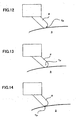
- the tool center point Tp may be set at various points with respect to the tool as shown in FIGS. 12-16 .
- FIG. 12 shows a case where the tool center point Tp is set at a tip of the tool 2.
- FIG. 13 shows a case where the tool center point Tp is set at a center of a semispherical end surface of a ball-end mill tool.
- FIG. 14 shows a case where the tool center point Tp is set at a cutting point on the semispherical end surface of the ball-end mill tool.
- FIG. 15 shows a case where the tool center point Tp is set at a center of an end face of a flat-end mill tool.
- FIG. 16 shows a case where the tool center point Tp is set at a cutting point on the end face of the flat-end mill tool.
- machining along a predetermined path at a predetermined velocity is realized with a simple machining program while driving the rotational-motion axes. Further, it is not necessary to create new machining programs by the CAM for various lengths of tools, to reduce a cycle time of machining.
Landscapes
- Engineering & Computer Science (AREA)
- Computing Systems (AREA)
- Theoretical Computer Science (AREA)
- Human Computer Interaction (AREA)
- Manufacturing & Machinery (AREA)
- Physics & Mathematics (AREA)
- General Physics & Mathematics (AREA)
- Automation & Control Theory (AREA)
- Numerical Control (AREA)
Description
- The present invention relates to a numerical controller for controlling a machine having an axis for turning a table or a workpiece holding stock on which a workpiece is mounted.
- There is known a machine tool having a plurality of linear motion axes and an axis for turning a table for mounting a workpiece, and further having an axis for tilting a tool head or the table. For example, in a five-axis machine tool as shown in
FIG. 1 , a table 1 is arranged movable in directions of rectangular axes of X, Y and atool head 2 is arranged movable in a direction of a Z-axis perpendicular to the X- and Y-axes, the table 1 is turned around a C-axis parallel to the Z-axis and further thetool head 2 is arranged to tilt around an A-axis parallel to the X-axis. Thus, aworkpiece 3 mounted on the table 1 is machined by a tool of thetool head 2 by driving the five axes. - Further, in a five-axis machine tool as shown in
FIG. 2 , atool head 2 is arranged movable in directions of three rectangular axes of X, Y, Z and the table 1 is arranged to turn around a C-axis on the Y-Z-plane and further tilt around an A-axis parallel to the X-axis, to machine aworkpiece 3 mounted on the table 1 by a tool of thetool head 2. - It has been necessary to create a machining program including commands for minute segments and issue the commands to servo systems for the respective axes using a CAM (computer-aided manufacturing) system for moving a distal end of the tool with respect to the
workpiece 3 along a predetermined path at a predetermined velocity while driving the A- and C-axes. - Specifically, in a machine tool having a C-axis for turning the table 1 and an A-axis for swinging a
tool head 2 in addition to linear-motion axes of X, Y, Z, as shown inFIG. 3 , it has been hardly possible to perform a cutting operation along a straight line L on theworkpiece 3 while turning the table 1 and varying an inclination angle of thetool head 2, as shown inFIG. 4 , by commanding a motion path of the straight line L by a single block. Thus, it has been necessary to divide the motion path into a plurality of segments and prepare commands for the plurality of segments. InFIG. 3 , Co presents a center of turning of the table 3, CS represents a reference position of angular position of the C-axis, the table 3 is turned so that a commanded angular position of the C-axis is moved to the reference position CS. A controlled point P of thetool head 2 is set at a center of turning of the tool. -
- N200 G01 G90 X Xc0 Y Yc0 Z Zc0 A 60.0 C30.0;
- N 301 X Xc1 Y Yc1 Z Zc1 A 45.0 C90.0;
- N 302 X Xc2 Y Yc2 Z Zc2 A 30.0 C150.0;
- In the block of N200, the code G01 commands cutting feed, the code G90 commands use of absolute value. According to the commands of the blocks, the respective axes of the machine tool are operated as shown in
FIGS. 5a-5c. FIG. 5a shows a state in which thetool 2 is positioned at a commanded position by the first block "N200", i.e. X coordinate value of Xc0, Y coordinate value of Yc0, Z coordinate value of Zc0, A-axis angle of 60 degree and C-axis angle of 30 degree, which is a machining start position of the second block "N 301".FIG. 5b shows a state in which the tool is positioned at a commanded position by the second block "N301", i.e. X coordinate value of Xc1, Y coordinate value of Yc1, Z coordinate value of Zc1, A-axis angle of 45 degree and C-axis angle of 90 degree, which is an end position of the second block "N 301" and also a start point of the third block "N 302". The machining is performed by the second block as indicated by the solid line.FIG. 5c shows a state in which the tool is positioned at an end point of the third block "N 302" to terminate the machining along the straight line L. - In the above example, the cutting operation along the straight line L is divided into only two blocks, but actually it is hardly possible to precisely machine the workpiece along the straight line L by the two blocks. Thus, it has been necessary to divide the motion path into a large number of blocks.
-
FIG. 4 is depicted with the C-axis stationary and thetool head 2 moved along the C-axis, and actually the C-axis is moved and the tool head as shown inFIG. 5 . In these figures, as viewed in the direction of Z-axis. - The above example is directed to the machine tool having the C-axis for turning the table 1 and the A-axis for tilting the
tool head 1 in addition to the linear-motion axes. The machine tool may have two axes for turning and for tilting the table 1 in addition to the linear-motion axes. - As described, in the machine tool having one axis for turning the table 1 and one axis for swinging the
tool head 2, or a machine tool having two rotational-motion axes for turning and for tilting the table 1, it is necessary to prepare a machining program commanding a minutely divided segments by the CAM system for performing the machining along a predetermined path at a predetermined velocity while turning the table. - Therefore, there arise the following problems.
- 1) A CAM system is necessary.
- 2) It is necessary to prepare a lengthy machining program including a large number of minute segments and thus a storage device of large capacity for storing the lengthy machining program is required.
- 3) Because of the lengthy machining program, it is necessary to rapidly transfer data from an external device to the CNC (Computerized Numerical Control) device in a DNC (Direct Numerical Control) operation in which the machining is performed while transferring a program from the external device to the CNC.
- 4) It takes a long time for the CNC device to analyze the lengthy program to make it difficult to perform the machining smoothly.
- 5) It is necessary to create a new machining program for using a tool having a different length.
- Document
JP 60- 230 207 EP-A-0 271 691 show a numerical controller for a robot having an axis for turning a table and a plurality of axes for moving the arm, whereby the work piece mounted on the table is processed by driving all axes. - An object of the present invention is to provide a numerical controller capable of precisely controlling a machine tool having an axis for turning a table with a simple machining program and easily coping with variation of a tool length.
- A numerical controller of the present invention is defined in attached
claim 1. Preferred embodiments are defined independent claims 2 to 9. -
-
FIG. 1 is a schematic view of a tive-axis machine tool having a rotational-motion axis for turning a table and a rotational-motion axis for tilting a tool head in addition to linear-motion axes; -
FIG. 2 is a schematic view of a five-axis machine tool having two rotational-motion axes for turning and tilting a table in addition to linear-motion axes; -
FIG. 3 is a schematic view showing a relationship of an A-axis for tilting the tool head and a C-axis for tuning the table; -
FIG. 4 is a schematic plan view showing a relationship of the table and the tool head in a cutting operation along a straight line while turning the table and varying a tilting angle according to the prior art; -
FIGS. 5a-5c are schematic plan views showing relative positions of the table and the tool head in the cutting operation according to the prior art as shown inFIG. 4 ; -
FIG. 6 is a schematic view showing a principle of the present invention in an embodiment for controlling the machine tool having the A-axis for tilting the tool head and the C-axis for tuning the table; -
FIG. 7 is a schematic plan view showing another way of machining in the embodiment as shown inFIG. 6 ; -
FIG. 8 is a block diagram of a numerical controller according to the present invention; -
FIG. 9 is a schematic plan view showing a relationship of the table and the tool in a cutting operation along a straight line while turning the table and varying a tilting angle according to the present invention; -
FIG. 10a-10c are schematic plan views showing relative positions of the table and the tool head in the cutting operation according to the present invention as shown inFIG. 9 ; -
FIG. 11 is a flowchart of processing of a tool center point control; -
FIG. 12 is a schematic view showing a tool center point set at a tip of the tool; -
FIG. 13 is a schematic view showing a tool center point set at a center of a semispherical end surface of a ball-end mill -
FIG. 14 is a schematic view showing a tool center point set at a cutting point on the semispherical end surface of the ball end mill -
FIG. 15 is a schematic view showing a tool center point set at a center of an end face of a flat-end mill; -
FIG. 16 is a schematic view showing a tool center point set at a cutting point of the end face of the flat-end mill; -
FIG. 17 is a schematic view showing an orientation vector and a shift amount in a case where the tool center point is set at a cutting point on an end surface of a ball-end mill; -
FIG. 18 is a schematic view showing an orientation vector and a shift amount in a case where the tool center point is set at a cutting point on an end face of a flat-end mill; -
FIG. 19 is a schematic view of a five-axis machine tool as a lathe to which the present invention is applicable. - A principle of the present invention will be described with respect to a machine tool having two rotational motion axes of a C-axis for turning a table and an A-axis for tilting a tool head in addition to linear motion axes of X, Y and Z, as shown in
FIG. 6 . The principle is applicable to a machine tool having rotational-motion axes other than the A-axis and C-axis as shown inFIG. 6 and a machine tool having two axes for turning and tilting the table. In this example, a tool center point Tp representing a position of a tool is set at a tip of the tool. - In this control of the tool center point, a workpiece coordinate system ΣW is defined by setting a position (Xw, Yw, Zw) of an origin thereof in a machine coordinate system ΣM. A controlled point P is set at a center of swinging motion of the tool head and a distance between the controlled point P and the tool center point Tp is stored as a tool length compensation amount H.
- A position (Xs, Ys, Zs) of the tool center point Tp at a start of machining in the workpiece coordinate system ΣW is obtained according to the following equations (1)-(3) based on a position (Xm, Ym, Zm) of the controlled point P at the start of machining in the machine coordinate system ΣM, an orientation of the tool (Am, Cm) and the tool length compensation amount H. Since the orientation of the tool is defined relatively to a workpiece on the table, the orientation of the tool is determined by an angle Am of rotation of the A-axis for tiling the tool and an angle Cm of rotation of the C-axis for turning the table 1 (workpiece 3). Angular positions (As, Cs) of the rotational-motion axes at the start of machining is defined as angular positions (Am, Cm) in the machine coordinate system ΣM.
- The position (Xm, Ym, Zm, Am, Cm) of the controlled point P including the angular positions of the rotational-motion axes at the start of machining in the machine coordinate system ΣM is stored as a position (Xo, Yo, Zo, Ao, Co) of the controlled point P at the preceding interpolation period for interpolating processing as described later, and the position (Xs, Ys, Zs) of the tool center point Tp at the start of machining in the workpiece coordinate system ΣW is stored as a position (Xj, Yj, Zj) of the tool center point Tp at the preceding interpolation period.


- The angular position Cm of the C-axis at the start of machining is stored as Cz. The coordinate value (Xr, Yr, Zr) of a center of turning of the table in the machine coordinate system ΣM is stored.
- In addition, the tool center point control may be started by shifting the position (Xm, Ym, Zm) of the controlled point P of the linear-motion axes in the machine coordinate system ΣM to be positioned at the tool center point Tp in the workpiece coordinate system at the start of machining. In this case, a tool length compensation vector V(Vx, Vy, Vz) is obtained using the orientation of the tool (Am, Cm) and the tool compensation amount H according to the following equations (4)-(6).


- The position (Xw, Yw, Zw) of the origin of the workpiece coordinate system ΣW is subtracted from the position (Xm, Ym, Zm) of the controlled point P in the machine coordinate system ΣM when the coordinate values of the X, Y and Z axes are shifted by the vector V, to obtain the position (Xs, Ys, Zs) of the tool center position at the start of machining in the workpiece coordinate system ΣW, according to the following equations. (7)-(9)


- After the machining start position (Xs, Ys, Zs) of the tool center point Tp in the workpiece coordinate system ΣW is thus obtained in the above-described manner, commands in the machining program are regarded as commands in the workpiece coordinate system ΣW (the commands are prepared as commands in the workpiece coordinate system ΣW) and interpolation processing is performed based on a velocity F commanded in the workpiece coordinate system ΣW. An interpolated position (Xc, Yc, Zc Ac, Cc) of the controlled point P in the machine coordinate system ΣM is obtained at every interpolation period At as follows;
- First, an interpolation of the tool center point Tp for the linear axes is performed based on the commanded velocity F to obtain an interpolation point (Xi, Yi, Zi) on the workpiece coordinate system ΣW. A length K1 of movement of the tool center point Tp in the interpolation processing period Δt is expressed by the following equation (10).

- A length of the block from the start position (Xs, Ys, Zs) to the end position (Xe, Ye, Ze) is obtained by the following equation (11).

- Thus, an interpolated position of the tool center point Tp in the workpiece coordinate system ΣM is obtained according the following equations using the preceding interpolation point (Xj, Yj, Zj). It should be noted that (Xj, Yj, Zj)=(Xs, Ys, Zs) at the start of machining.


- Interpolations for the rotational-motion axes of the A-axis and the C-axis are performed from a start position (As, Cs) to the end position (Ae, Ce) to obtain an interpolation point (Ai, Ci). The position of the interpolation point (Ai, Ci) is distributed proportionally at the same rate as that of distribution of the interpolation of movement of the tool center point Tp from the start position (Xs, Ys, Zs) to the end position (Xe, Ye, Ze).
- Using a ratio K2 expressed by the following equation (15),


- The interpolation point (Xi, Yi, Zi) of the tool center point Tp for the linear-motion axes in the workpiece coordinate system ΣW is corrected by the turning angle of the table and transformed at every interpolation processing period, to obtain a coordinate position (Xa, Ya, Za) of the tool center point Tp in the machine coordinate system ΣM according to the following equations (18)-(20).


- The tool length compensation vector V(Vx, Vy, Vz) is calculated using the interpolated position (Ai) of the A-axis and the tool length compensation mount H according to the following equations (21)-(23) at every interpolation processing period.


- The position (Xc, Yc, Zc) of the controlled point P in the machine coordinate system ΣM is obtained by adding the tool length compensating vector V to the position (Xa, Ya, Za) of the tool center point Tp in the machine coordinate system ΣM according to the following equation (24) at every interpolation processing period. Further, the values of (Ai, Ci) are stored as (Ac, Cc).

- Thus, the interpolated position (Xc, Yc, Zc) of the controlled point P in the machine coordinate system ΣM is obtained.
- A difference between the interpolated position (Xc, Yc, Zc) of the controlled point P in the present interpolation period and the interpolated position (Xo, Yo, Zo) of the controlled point P in the preceding processing period is outputted to the servo systems for the linear axes of X, Y, Z as motion amounts. Also, differences between the interpolated positions (Ac, Cc) of the rotational-motion axes and the interpolated positions (Ao, Co) in the preceding interpolation period are outputted to the servo systems of the rotational-motion axes of A and C, respectively.
- Then, the interpolated position (Xc, Yc, Zc) of the controlled point P are stored as the preceding interpolated position (Xo, Yo, Zo) and the interpolated angular positions (Ac, Cc) of the rotational-motion axes are stored as the preceding interpolated positions (Ao, Co) for use in the interpolation processing in the next processing period.
- In the case where the next command is of a command to terminate the tool center point control, the commands obtained by the following equations (25)-(27) are regarded as programmed commands (Xp, Yp, Zp) for the subsequent commands.


- Thus, precise machining is performed on the workpiece mounted on the turning table with the simple machining program by the above-described interpolation processing.
- In the above example, the workpiece coordinate system is not considered with respect to A- and C- axes for simplification. The calculations may be performed by taking the workpiece coordinate system into consideration with respect to the A- and C- axes in the same manner as the X-, Y- and Z- axes.
- In the above description, the workpiece coordinate system ΣW is set to the table 1 at a start of the tool center point control, and commands of the machining program are executed in the workpiece coordinate system ΣW. Since the workpiece coordinate system ΣW turns with the turn table 1, a relationship between a machining path of the tool center point P commanded by the machining program for determining a shape of the machining in the workpiece coordinate system ΣW and an actual machining path on the
workpiece 3 mounted on the table 1 is fixed. Thus, the machining shape on the workpiece defined in the workpiece coordinate system ΣW is realized on theworkpiece 3. - The commands of the machining program may be prepared as commands in a stationary workpiece coordinate system. Specifically, it is possible to prepare the commands of the machining program in the stationary workpiece coordinate system which does not turn with the table 1 and does not have influences from the turning of the table 1.
- In this case, the processing of the calculation according to the equation (10) and the subsequent processing are performed using a position (Xe1, Ye1, Ze1) obtained by calculations according to the following equations (28)-(30) and used in place of the end position (Xe, Ye, Ze). Thus, the position (Xe1, Ye1, Ze1) of the tool center point Tp in the set workpiece coordinate system ΣW turning with the turning table 1 is obtained based on the commanded position (Xe, Ye, Ze) in the stationary workpiece coordinate system ΣWR, as shown in
FIG. 7 , and the obtained coordinate position is regarded as the commanded position in the set workpiece coordinate system ΣW and the processing of the calculation according to the equation (10) and the subsequent processing are performed.


- The orientation of the tool may be defined by an orientation vector (I, J, K). The interpolation of the angular positions of the rotational axes can be automatically performed based on the orientation vector by the numerical controller (CNC). In this case, the end position (Xe, Ye, Ze, Ae, Ce) of the block is replaced by (Xe, Ye, Ze, Ie, Je, Ke) using the orientation vector (Ie, Je, Ke) indicating an orientation of the tool in the workpiece coordinate system ΣW. The angular positions (Ae, Ce) of the rotational axes are calculated based on the orientation vector (Ie, Je, Ke) and the foregoing processing is performed using the calculated angular positions (Ae, Ce) of the rotational axes.
- Further, the orientation of the tool may be designated by the orientation vector (I, J, K) and a shift amount therefrom. In the case where the tool center point Tp is set at a cutting point on a semispherical end surface of a ball end mill tool, as shown in
FIG. 17 , an orientation tangent perpendicular to a surface of theworkpiece 3 is defined by the orientation vector (I, J, K) and the orientation of the tool is designated by a shift angel Q of a line tangent to a proceeding direction commanded by the program with respect to the orientation vector (L, J, K). In this case, the end position (Xe, Ye, Ze, Ae, Ce) of the block is replaced by (Xe, Ye, Ze, Ie, Je, Ke, Qe) using the orientation vector (Ie, Je, Ke) indicating the orientation perpendicular to the surface of the workpiece and the Qe indicating the shift angle of the line tangent to the proceeding direction commanded by the program. The angular positions (Ae, Ce) of the rotational axes are calculated based on the orientation vector (Ie, Je, Ke), the shift angle Qe and the proceeding direction commanded by the program, and a center of the semi-sphere of the end of the tool is obtained based on the orientation vector (Ie, Je, Ke) and a tool radius compensation amount D. The obtained center of the semi-sphere is used as the tool center point, and the foregoing processing is performed using the calculated angular positions (Ae, Ce) of the rotational axes. - The shift angle Q may be defined by Q1 indicating the shift angle of the line tangent to the proceeding direction commanded by the program and Q2 indicating a shift angle of the line perpendicular to the proceeding direction commanded by the program. In this case also, the angular positions (Ae, Ce) of the rotational axes are calculated, and a center of the semi-sphere of the end of the tool is obtained based on the orientation vector (Ie, Je, Ke) and the tool radius compensation amount D. The obtained center of the semi-sphere is used as the tool center point, and the foregoing processing is performed using the calculated angular positions (Ae, Ce) of the rotational axes.
- In the case where the tool center point Tp is set at a cutting point on an end face of a flat end mill tool, as shown in
FIG. 18 , the orientation of the tool is defined by an orientation vector (I, J, K) or positions of the rotational axes and a distance between the cutting point on the tip surface, and a distance between the cutting point on the end face and a center of the end face is defined by a tool radius compensation amount D. In the case of defining the orientation of the tool by the orientation vector (I, J, K), the end position is set to (Xe, Ye, Ze, Ie, Je, Ke) using the orientation vector (Ie, Je, Ke) indicating an orientation of the tool. The angular positions (Ae, Ce) of the rotational axes are calculated based on the orientation vector (Ie, Je, Ke), and the position of the center of the end face of the tool is obtained by shifting the tool center point Tp by the tool radius compensation amount D in the direction perpendicular to the orientation (Ie, Je, Ke) on a plane defined by a proceeding direction commanded by the program and the orientation (Ie, Je, Ke). The obtained center of the end face of the tool is used as the tool center point, and the foregoing processing is performed using the calculated angular positions (Ae, Ce) of the rotational axes. -
FIG. 8 shows a numerical controller (CNC) 100 for carrying out the tool center point control according to the present invention. - In
FIG. 8 , aCPU 11 reads a system program stored in aROM 12 through abus 20 and control the wholenumerical controller 100 according to the system program. ARAM 13 stores temporary storage data for arithmetic operation, display data and various set data inputted through a display/MDI unit 70 by an operator. ACMOS memory 14 is backed up by a battery to fuction as a nonvolatile memory for retaining the stored data when a power supply is turned off. TheCMOS memory 14 stores a machining program read through aninterface 15 or the display/MDI unit 70. Various system programs for performing processing for creating/editing of the machining program in an editing mode and processing for an automatic operation of the machine are written in theROM 12 in advance. - The machining programs for carrying out the tool center point control of the present invention may be stored in the
CMOS memory 14 through theinterface 15 or the display/MDI unit 70. - The
interface 15 enables connection between thenumerical controller 100 and anexternal device 72 such as an adapter. The machining programs and various parameters are read from theexternal device 72 through theinterface 15. The machining program edited in thenumerical controller 100 can be stored in a storage device through theexternal device 72. A PC (programmable controller) 16 outputs signals to a peripheral device of the machine, such as actuator of a robot hand for changing tools, through an I/O unit 17 in accordance with a sequential program. Also, thePC 16 receives signals from switches of an operation panel arranged on the machine tool and performs necessary processing on the signals to be transferred to theCPU 11. - The display/
MDI unit 70 is a manual data input device having a display and a keyboard, and aninterface 18 receives commands and data from the display/MDI unit 70 and transfers the received command and data to theCPU 11. Aninterface 19 is connected to anoperation panel 71 having a manual pulse generator. - Axis-control circuits 30-34 for respective axes output commands to servo amplifiers 40-44 for the respective axes in accordance with motion commands from the
CPU 11. The servo amplifiers 40-44 drive respective servomotors 50-54 in accordance with the commands from the axis-control circuits 30-34. The servomotors 50-54 for respective axes have position/velocity detectors (not shown) and signals from the position/velocity detectors are fed back to the axis-control circuits 30-34 to perform feedback controls of position and velocity of the servomotors 50-54. - The servomotors 50-54 respective drive the linear-motion axes of X, Y, Z and the rotational-motion axis of A and C of the five-axis machine tool as shown in
FIGS. 1 and2 . A spindle-control circuit 60 receives a spindle rotation command and outputs a spindle velocity command to aspindle amplifier 61. Thespindle amplifier 61 drives aspindle motor 62 at a speed commanded by the spindle velocity command from the spindle-control circuit 60. Aposition corder 63 outputs feedback pulses synchronized with rotation of thespindle motor 62 to the spindle-control circuit 60 for velocity control of thespindle motor 62. - With the above arrangements, the
numerical controller 100 controls the five-axis machine tool as shown inFIGS. 1 and2 to perform the tool center point control. - Hereinafter, examples of the tool center point control using the numerical controller for controlling the five-axis machine tool as shown in
FIG. 1 . - First, the workpiece coordinate system ΣW is defined by setting a position (Xw, Yw, Zw) of an origin of the workpiece coordinate system in the machine coordinate system ΣM. Further, a position (Xr, Yr, Zr) of a center of turning of the turn table 1 (a workpiece 3) is set and stored as a parameter. In the following example, it is set that Xw=Xr and Yw=Yr, but coordinate values (Xw, Yw) and (Xr, Yr) are not necessarily equal to each other.
- Commands in the machining program for the tool center point control for machining the
workpiece 3 turning with the table 1 are prepared with respect to the workpiece coordinate system ΣW. Thus, the workpiece coordinate system ΣW is defined at the start of the tool center point control to be fixed to and turned with the table 1. - The following machining program is prepared and executed for machining the
workpiece 3 turning with the table along a straight line L, as shown inFIG. 9 . -
- N100 G54 H01 C30.0; (Definition of workpiece coordinate system and designation of tool length compensation number)
- N101 G90 G00 X0.0 Y150.0 Z86.603 A60.0 C30.0; (Positioning of a start point)
- N200 G43.4; (Start of tool center point control)
- N301 G01 X-86.603 Y-50.0 Z0.0 A30.0 C150.0 F5000; (Cutting along straight line L)
- N400 G49; (Termination of tool center point control)
- In the block N100, the
numerical controller 100 stores and set the position (Xw, Yw, Zw) of the origin of the workpiece coordinate system designated by the code G54 and a tool length compensation H for the tool length compensation number 01. In this example, a value of the tool length compensation number H01 is 100.0, and the origin of the workpiece coordinate system and the center of turning of the table 1 are set as (Xw, Yw, Zw) = (Xr, Yr, Zr) = (200.0, 200.0, 100.0). - In the statement of N101, the code "G90" designates an absolute command, the code "G00" designates positioning, and the position of the controlled point P in the workpiece coordinate system ΣW is designated as X=0.0, Y=150.0, Z=86.603, A=60.0, C=30.0.
- The position of the controlled point P in the workpiece coordinate system ΣW is converted into a position (Xm, Ym, Zm, Am, Cm) in the machine coordinate system ΣM, as follows;


- The respective axes of the machine tool are moved to the above positions by the command in the block N101, as shown in
FIG. 10a . - The code "G43.4" is a command for starting the control of the tool center point Tp and thereinafter a path of motion of the tool center point Tp is designated by the program to the end of the control. The machining start position (Xs, Ys, Zs) of the tool center point Tp is obtained based on the present position of the controlled point P, the orientation (Am, Cm) of the tool and the tool length compensation amount H. In the case where the present position of the controlled point P is (200.0, 350.0, 186.603), the orientation of the tool is (A 60.0, C 30.0) and the tool length correction amount H =100.0, the position (Xs, Ys, Zs)= (200.0, 350.0, 186.603) of the tool center point Tp is obtained according to the above-mentioned equations (1)-(3), as follows;


- The above coordinate values are also set as (Xj, Yj, Zj) and the position (Xm, Ym, Zm, Am, Cm) of the controlled point P in the machine coordinate system is set as (Xo, Yo, Zo, Ao, Co). Further, the angular position (30.0) of the C-axis is set as Cz.
- This state is shown in
FIG. 10a where thetool 2 is positioned at a start position of the machining along a straight line L. - In the block of N301, the code "G01" represents a command for cutting feed to command to feed the tool center point Tp moves to (-86.603, -50.0, 0.0), the orientation of the tool to a target value (A=30.0, C=150.0) at the velocity of 5000 mm/min.
- Interpolation is performed from the position (Xs, Ys, Zs)=(0.0, 100.0, 0.0) of the tool center point Tp at the start of machining to the commanded end position (Xe, Ye, Ze) = (-86.603, -50.0, 0.0) with respect to the X-, Y- and Z-axes, to obtain interpolation points (Xi, Yi, Zi). Namely, the interpolation points (Xi, Yi, Zi) are obtained according to the equations (10)-(14). Assuming that the interpolation period Δt =1msec,


- With respect to the A- and C- axes, interpolation is performed from the present position (A=60.0, C=30.0) to the commanded position (A= 30.0, C=150.0) to obtain the interpolation points (Ai, Ci). The position of the interpolation points are set at the same rate of the motion of the tool center point Tp from the start point (Xs, Ys, Zs)=(0.0, 100.0, 0.0) to the end point (Xe, Ye, Ze) = (-86.603, -50.0, 0.0). Thus, Ai and Ci are obtained according to the equations (16) and (17), as follows;


- For example, when the interpolation point (Xi, Yi, Zi) is (-43.302, 25.0, 0.0), Ai = 45.0 and Ci = 90.0, as shown in
FIG. 10b . - The position of the interpolation point (Xa, Ya, Za) for the motion of the tool center point Tp in the machine coordinate system ΣM is obtained according to the equations (18)-(20). For example, as shown in
FIG. 10b , when the interpolated position of the C-axis Ci = 90.0, the position of the interpolation point (Xi, Yi, Zi) in the X-, Y-, Z- axes is (-43.302, 25.0, 0.0) and the interpolated position (Xa, Ya, Za) =(175.0, 243.302, 100.0) of the tool center point Tp in the machine coordinate system ΣM is obtained according to the equations (18)-(20), as follows;


- Also, the tool length compensation vector V is obtained based on the interpolated position Ai of the A-axis. When Ai=45.0, the tool length correction vector V = (0.0, 70.711, 70.711) according to the equation (21)-(22).


- The position (Xc, Yc, Zc) of the controlled position P is obtained by adding the tool length correcting vector V to the interpolated position (Xa, Ya, Za) of the tool center point Tp in the machine coordinate system ΣM, according to the equation (24).


- A difference between the position (Xc, Yc, Zc) of the controlled position Tp in the present interpolation period and the position (Xo, Yo, Zo) of the controlled position Tp in the preceding interpolation period is outputted to the axis control circuits 30-32 as a motion amount for the linear axes of X, Y and Z. Simultaneously, the interpolated positions (Ao, Co) of the A-, C- axes in the present interpolation processing period and the interpolated positions (Ai, Ci) = (Ac, Cc) for the turning-motion axes A and C in the preceding interpolation processing period is outputted to axis-
control circuits - As described, the tool center point Tp is moved to the target position commanded by the block N301 while performing the interpolation processing to successively shifting the position of the tool center point Tp by driving the X-, Y-, Z-, A- and C- axes to the interpolated positions.
FIG. 10c shows a state where the tool center point Tp reaches to the machining end point. - The code "G49" in the block N400 is a command of terminating the control of the motion of the tool center point. The final interpolation point (Xc, Yc, Zc) of the controlled point P is transformed into the position in the workpiece coordinate system according to the equations (25)-(27), and transformed position in the workpiece coordinate system are regarded as the programmed command (Xp, Yp, Zp).


- Thus, the cutting along the straight line L is completed as shown
FIG. 10c . In the example of the conventional machining program for cutting along the straight line L as described referring toFIGS. 3-5 , it is described that the cutting is performed by the commands of the two blocks of "N301" and "N302" for the sake of simplification, however it is hardly possible to perform the machining of high precision with only two blocks and it is actually required to prepare a large number of blocks. According to the present invention, the machining is commanded by only one block of "N301", to simplify the machining program. - In the above described example, the orientation of the tool is defied by the angular position of A-axis representing angle of tilting the tool and the angular position of the C-axis representing the angle of turning of the table 1. The orientation of the tool may be defined by the orientation vector V, as described, and the numerical controller may automatically calculate the interpolation of the rotational-motion axes.
- In this case, the designated values of A=30.0 and C= 150.0 in the block "N301" of the above program corresponds to an orientation of X=10.866, Y=-0.5, Z= 0.577 in the workpiece coordinate system ΣW. Therefore, A 30.0 and C 150.0 are replaced by "I -0.866 J -0.5 K 0.577", and based on these values the numerical controller may calculate the values of A=30.0 and C= 150.0.
- The case where commands in the machining program are prepared with respect to the stationary workpiece coordinate system ΣWR which does not rotate with the table and does not have influence from the turning of the table.
- The following machining program is prepared for performing the machining along a straight line L as performed by the Example 1.
-
- N100 G54 H01 C30.0; (Selection of workpiece coordinate system, Designation of tool length compensation number)
- N101 G90 G00 X0.0 Y150.0 Z86.603 A60.0 C30.0; (Positioning of start point)
- N200 G43.4; (Start of tool center point control)
- N301 G01 X0.0 Y100.0 Z0.0 A30.0 C150.0 F5000; (Cutting along straight line L)
- N400 G49; (Termination of tool center point control)
- This example differs from the Example 1 in that the block "N301" describes "G01 X0.0 Y100.0 Z0.0 A30.0 C150.0 F5000", whereas the block "N301" of the example-1 describes "G01 X-86.603 Y-50.0 Z0.0 A30.0 C150.0 F5000".
- Since the commands in the block "N301" in this example are prepared as commands of the position of the tool center point Tp in the stationary workpiece coordinate system ΣWR, the processing same as that in the Example-1 can be performed by transforming the position of the tool center point Tp into the position in the workpiece coordinate system ΣW turning with the table.
- Specifically, the position (Xe1, Ye1, Ze1) in the workpiece coordinate system ΣM is obtained based on the coordinate values (Xe, Ye, Ze) of the target position designated by this block according to the equations (28)-(30), and the obtained coordinate values (Xe1, Ye1, Ze1) are used in place of (Xe, Ye, Ze).


- As described, the position designated by the transformed coordinate position (Xe1, Ye1, Ze1)=(-86.603, 50.0, 0.0) are identical to the coordinate position "X=-86.608, Y=-50.0, Z=0.0" of the command in the block N301 in the Example 1. The subsequent processing is the same as the processing in the Example-1.
-
FIG. 11 shows a flowchart of processing for the tool center point control to be executed by theprocessor 11 of thenumerical controller 100. - The
processor 11 starts the processing as shown inFIG. 11 when a command "G43.4" for starting the tool center point control in the machining program. The workpiece coordinate system ΣM (Xw, Yw, Zw) and the tool length compensation amount H are set and stored as shown in Example-1 and Example-2 before the command "G43.4" for starting the tool center point control is read. Also, the tool center point P has been positioned to a machining start position of the tool center point control. - When the command "G43.4" for starting the tool center point control is read, the position (Xs, Ys, Zs) of the tool center point Tp for the start of machining in the workpiece coordinate system ΣW is obtained based on the present position (Xm, Ym, Zm) of the controlled point P, the angular position Am of A-axis, the angular position of the C-axis and the tool length compensation amount H by executing the arithmetic operation according to the equation (Step S1).
- The position (Xm, Ym, Zm) is stored as the position (Xo, Yo, Ao, Co) at the immediately preceding interpolating processing period, and the position (Xs, Ys, Zs) of the tool center point Tp is stored as the immediately preceding interpolated position (Xj, Yj, Zj). Further, (Am, Cm) is stored as (As, Cs) and Cm is stored as Cs (Step (S2).
- Then, the next block is read (Step S3) and it is determined whether or not the read block is a command (G49) of terminating the tool center point control (Step S4). The cutting feed command (G 01) next to the command (G43.4) for starting the tool center point control is read and the procedure proceeds to Step S5. In Step S5, the length K1 by which the tool center point Tp is to move for the interpolation period and the machining length D commanded by the block by performing the arithmetic operation according to the equations (10) and (11), based on the commanded position (Xe, Ye, Ze) and the present position (Xs, Ys, Zs) of the tool center point Tp and the commanded velocity F.
- The interpolated position (Xi, Yi, Zi) is obtained by performing the arithmetic operation according to the equations (12)-(14) using the obtained K1 and D, the commanded position (Xe, Ye, Ze) and the preceding position (Xj, Yj, Zj) (Step S6). The proportional coefficient K2 is obtained according to the equation (15) (Step S7) and the interpolated positions Ai and Ci of the A-axis and the C-axis, respectively are obtained according to the equations (16) and (17) (Step S8).
- The interpolated position (Xi, Yi, Zi) is rotated to obtain the position (Xa, Ya, Za) of the tool center point Tp in the machine coordinate system ΣM by performing the arithmetic operation according to equations (18)-(20) using the obtained turning angle Ci of the table 1 (Step S9).
- Further, the tool length compensation vector V(Vx, Vy, Vz) is obtained by performing the arithmetic operation according to the equations (21)-(23) using the angular position Ai which is the tilting angle of the A-axis (Step S10). Then, the tool length compensation vector V(Vx, Vy, Vz) is added to the position (Xa, Ya, Za) of the tool center point Tp in the machine coordinate system ΣM according to the equation (24), to obtain the position (Xc, Yc, Zc) of the controlled point P in the machine coordinate system ΣM (Step S11).
- The coordinate data (Xi, Yi, Zi) are stored as (Xj, Y, Zj) and the coordinate data (Ai, Ci) are stored as (Ac, Cc) (Step S12) for the next interpolating processing. The present position (Xo, Yo, Zo) of the controlled position P is subtracted from the position (Xc, Yc, Zc) of the controlled position P obtained by the interpolation and the obtained difference is outputted to the servo system as the command for the
servomotors servo motors - The position (Xc, Yc, Zc) of the controlled point P, and the interpolated positions of the A- and C- axes are stored as the present position (Xo, Yo, Zo), and the present positions Ao, Co, respectively (Step S14). Then, it is determined whether or not the tool center point Tp reaches the end of the block (Step S 15). If the tool center point Tp does not reach the end of the block, the procedure returns to Step S6.
- Subsequently, the processing of Steps S6-S16 is repeatedly executed until the tool center point Tp reaches the end of the block to perform the interpolation to the commanded position to drivingly control the respective axes. When it is determined that the tool center point Tp reaches the end of the block at Step S15, the end position (Xe, Ye, Ze, Ae, Ce) is stored as the start position of the next block (Step S16) and the procedure returns to Step S3. The processing of Step S3 and the subsequent steps is repeatedly executed unless the command of terminating the tool center point control is read to continue the machining. When the command of terminating the tool center point control is read, the procedure proceeds from Step S4 to Step 17 where the coordinate position (Xp, Yp, Zp) is calculated according to the equations (25)-(27) to be used as the program command, to terminate the tool center point control.
- In the case where command in the program for the tool center point control are prepared in the stationary workpiece coordinate system ΣMR not turning with the table 1, the commanded position (Xe, Ye, Ze) is transformed to the position (Xe1, Ye1, Ze1) in the workpiece coordinate system ΣM turning with the table according to the equations (28)-(30), and the processing as shown in
FIG. 11 is executed using the transformed position (Xe1 Ye1, Ze1) in place of the commanded position (Xe, Ye, Ze). - In the case of obtaining the tool length compensation vector V in advance to perform the compensation, the processing of Step S1 is modified. In this case, the present position (Xm, Ym, Zm) of the controlled position P in the machine coordinate system ΣM, the present position (Am, Cm) of the A- and C- axes are read, and the tool length compensation vector V is obtained according to the equations (4)-(6) using the present position of the A- and C-axes and the tool length compensation amount H, and the axes of X, Y, Z proceed by the tool length compensation vector V and the positions of the X-, Y-, Z- axes are read. The position (Xs, Ys, Zs) of the tool center point Tp in the workpiece coordinate system ΣW at the start of machining is obtained according to the equations (7)-(9) using the read position as the present position (Xm, Ym, Zm) of the controlled point P.
- In the foregoing embodiment, the present invention is applied to a machine tool having one axis (C-axis) for turning the table and one axis (A-axis) for tilting the tool head, the present invention is applicable to a machine tool having two axes for turning and tilting the table or another axis other than the A-axis and the C-axis. Also, the present invention is applicable to a machine tool having the C-axis for turning the table but not having the A-axis for tiling the tool head. In this case, all the command values and the present value of the A-axis are set to "0" or to be constant.
- Further, according to the present invention, the five-axis machining can be realized in a lathe. For example, the present invention is applicable to a lathe having a C-axis for turning a
workpiece 3 and a B-axis for tilting atool 2, as shown inFIG. 19 . - In the lathe shown in
FIG. 19 , theworkpiece 3 is fixed to aworkpiece holding stock 4 by a jig, and thetool 2 is arranged to be movable in the directions of the rectangular axes of X, Y, Z and also arranged to tilt or swivel along the B-axis parallel to the Y-axis. The machine tool of the lathe shown inFIG. 19 differs from the machine tool shown inFIG. 1 only in that the B-axis for tilting thetool 2 is used in place of the A-axis for tilting the tool head. Thus, the present invention is applicable to the lathe by substituting the B-axis for the A-axis. - The tool center point Tp representing a position of the tool is set at a tip of the tool in the foregoing embodiments. The tool center point Tp may be set at various points with respect to the tool as shown in
FIGS. 12-16 . -
FIG. 12 shows a case where the tool center point Tp is set at a tip of thetool 2.FIG. 13 shows a case where the tool center point Tp is set at a center of a semispherical end surface of a ball-end mill tool.FIG. 14 shows a case where the tool center point Tp is set at a cutting point on the semispherical end surface of the ball-end mill tool.FIG. 15 shows a case where the tool center point Tp is set at a center of an end face of a flat-end mill tool.FIG. 16 shows a case where the tool center point Tp is set at a cutting point on the end face of the flat-end mill tool. - According to the present invention, in a machine tool having a rotational-motion axis for turning a table on which a workpiece is mounted and a rotational-motion axis for tilting a tool head or the table in addition to a plurality of linear motion axes, machining along a predetermined path at a predetermined velocity is realized with a simple machining program while driving the rotational-motion axes. Further, it is not necessary to create new machining programs by the CAM for various lengths of tools, to reduce a cycle time of machining.
Claims (9)
- A numerical controller for controlling a machine tool having a tool (2), a plurality of linear-motion axes (X, Y, Z) and at least one rotational-motion axis (A,B,C) for a table (1) or a workpiece holding stock (4) on which a workpiece (3) is mounted, said controller comprising:motion commanding means adapted for providing a command of motion path for said linear-motion axes (X, Y, Z), a command of velocity of said tool (2) with respect to said workpiece (3), a predetermined tool radius compensation amount (D), a predetermined tool length compensation amount (H), and a command of rotational motion of the rotational-motion axis (A, B, C) for defining an orientation of said tool (2) with respect to said table (1) or stock (4);coordinate system defining means adapted for defining a coordinate system (ΣW) with respect to said table (1) or stock (4);first interpolation means adapted for performing interpolation on the commanded motion path using the commanded velocity in said coordinate system (ΣW) to obtain interpolated position data for said linear-motion axes (X, Y, Z);second interpolation means adapted for interpolating the rotational motion of said rotational-motion axis (A, B, C) based on the commanded motion path and the commanded velocity to obtain interpolated position data for the rotational-motion axis (A, B, C);tool center point position calculation means adapted for calculating a position (Xi, Yi, Zi) of a tool center point (Tp) set to the tool (2) by compensating the interpolated position data obtained by said first interpolation means based on the predetermined tool radius compensation amount (D);transformation means adapted for obtaining a transformed coordinate position (Xa, Ya, Za) in a coordinate system (EM) defined with respect to the machine tool by transforming the position (Xi, Yi, Zi) of the tool center point (Tp) based on the interpolated position data for the rotational-motion axis (A, B, C) for the table (1);tool length compensation vector calculation means adapted for calculating a tool length compensation vector (V) based on the predetermined tool length compensation amount (H) and the orientation of said tool (2); andcorrection means adapted for correcting the transformed coordinate position (Xa, Ya, Za) by adding the tool length compensation vector (V) to the transformed coordinate position to obtain a position (Xc, Yc, Zc) of a controlled point (P) of the tool (2) in the coordinate system (EM) defined with respect to the machine tool, the controlled tool point (P) being spaced from the tool centre point (Tp),wherein motion commands for the linear-motion axes (X, Y, Z) will be outputted based on the interpolated position data for the linear-motion axes (X, Y, Z) corrected by said correction means, and motion commands for the rotational-motion axis (A, B, C) will be outputted based on the interpolated position data for the rotational-motion axis (A, B, C) so that the tool center point (Tp) set to the tool (2) will be moved along the commanded motion path at the commanded velocity.
- A numerical controller according to claim 1, wherein said machine tool has an axis (A, B) for tilting said tool (2) with respect to said table (1) or stock (4) as the rotational-motion axis.
- A numerical controller according to claim 1, wherein said machine tool has an axis (C) for tilting said table (1) or stock (4) with respect to said tool (2) as the rotational-motion axis.
- A numerical controller according to claim 1, wherein said orientation of to (2) is provided as a command for rotational position of said rotational-motion axis (A, B, C).
- A numerical controller according to claim 1, wherein said orientation of tool (2) is provided as an orientation vector.
- A numerical controller according to claim 1, wherein said coordinate system defining means defines a coordinate system (ΣW) which turns with said table (1) or stock (4), and said motion commanding means provides the command for motion path of said linear-motion (axes (X, Y, Z)) in the coordinate system (ΣW) which turns with said table (1) or stock (4).
- A numerical controller according to claim 1, wherein said motion commanding means provides the command of motion path for said linear-motion axes (X, Y, Z) by transforming a command of motion path for said linear-motion axes commanded in a coordinate system which does not turn with said table (1) or stock (4) into a command of motion path in a coordinate system which turns with said table.
- A numerical controller according to claim 1, wherein the command of motion path for said linear-motion axes (X, Y, Z) is commanded for a cutting point on a semispherical end surface of a ball end mill tool.
- A numerical controller according to claim 1, wherein the command of motion path for said linear-motion axes (X, Y, Z) is commanded for a cutting point on an end face of a flat end mill tool.
Applications Claiming Priority (2)
| Application Number | Priority Date | Filing Date | Title |
|---|---|---|---|
| JP2001318147 | 2001-10-16 | ||
| JP2001318147 | 2001-10-16 |
Publications (3)
| Publication Number | Publication Date |
|---|---|
| EP1302829A2 EP1302829A2 (en) | 2003-04-16 |
| EP1302829A3 EP1302829A3 (en) | 2004-08-04 |
| EP1302829B1 true EP1302829B1 (en) | 2008-11-26 |
Family
ID=19135910
Family Applications (1)
| Application Number | Title | Priority Date | Filing Date |
|---|---|---|---|
| EP02257109A Expired - Fee Related EP1302829B1 (en) | 2001-10-16 | 2002-10-14 | Numerical controller |
Country Status (3)
| Country | Link |
|---|---|
| US (1) | US6775586B2 (en) |
| EP (1) | EP1302829B1 (en) |
| DE (1) | DE60230009D1 (en) |
Cited By (2)
| Publication number | Priority date | Publication date | Assignee | Title |
|---|---|---|---|---|
| DE102012003196B4 (en) * | 2011-02-25 | 2016-05-12 | Fanuc Corporation | A numerical control apparatus having a speed control function for a multi-axis machining apparatus |
| CN108705684A (en) * | 2018-04-24 | 2018-10-26 | 华侨大学 | A kind of five axis stone material slab cutting machine Three-dimension process circular saw pose acquisition methods |
Families Citing this family (57)
| Publication number | Priority date | Publication date | Assignee | Title |
|---|---|---|---|---|
| WO2004022270A1 (en) * | 2002-09-03 | 2004-03-18 | Kennametal Inc. | Toolholder |
| US7287939B2 (en) * | 2003-01-29 | 2007-10-30 | Josef Koch | Method for controlling relative displacements of a tool against a workpiece |
| DE10330828B4 (en) * | 2003-07-08 | 2006-09-21 | Mtu Aero Engines Gmbh | Method and device for milling free-form surfaces |
| JP2005071016A (en) * | 2003-08-22 | 2005-03-17 | Fanuc Ltd | Numerical control device |
| JP2005128686A (en) * | 2003-10-22 | 2005-05-19 | Fanuc Ltd | Numerical control apparatus |
| US20060074499A1 (en) * | 2004-10-01 | 2006-04-06 | Rafie Hamidpour | System and method for industrial process control |
| WO2006102517A2 (en) * | 2005-03-23 | 2006-09-28 | Hurco Companies, Inc. | Method of tolerance-based trajectory planning and control |
| JP4137909B2 (en) * | 2005-04-13 | 2008-08-20 | ファナック株式会社 | Robot program correction device |
| JP2006309645A (en) * | 2005-05-02 | 2006-11-09 | Fanuc Ltd | Curve interpolation method |
| JP4008466B2 (en) * | 2005-10-05 | 2007-11-14 | ファナック株式会社 | Processing equipment |
| US20070142966A1 (en) * | 2005-12-20 | 2007-06-21 | Khalid Mirza | Process for moving a robot |
| DE102006022831A1 (en) * | 2006-05-16 | 2007-11-22 | Siemens Ag | Method of controlling a grinding machine and numerically controlled grinding machine |
| US7933677B2 (en) * | 2006-08-04 | 2011-04-26 | Hurco Companies, Inc. | System and method for surface finish management |
| US8024068B2 (en) | 2006-08-04 | 2011-09-20 | Hurco Companies, Inc. | Machine tool control system |
| TWI353496B (en) * | 2006-08-04 | 2011-12-01 | Hurco Co Inc | System and method and computer readable medium for |
| US8725283B2 (en) * | 2006-08-04 | 2014-05-13 | Hurco Companies, Inc. | Generalized kinematics system |
| JP2008287471A (en) * | 2007-05-17 | 2008-11-27 | Fanuc Ltd | Numerical control method for five-axis processing machine |
| JP5280665B2 (en) * | 2007-10-26 | 2013-09-04 | オークマ株式会社 | Numerical control device with manual shift operation function |
| JP4351281B2 (en) * | 2007-12-13 | 2009-10-28 | ファナック株式会社 | Numerical control device for controlling a 5-axis machine |
| JP4467625B2 (en) * | 2008-03-31 | 2010-05-26 | 三菱電機株式会社 | Numerical control apparatus and numerical control method |
| US7845257B2 (en) * | 2008-09-04 | 2010-12-07 | Mori Seiki Co., Ltd. | Ultra-precision machine tool |
| JP2010152550A (en) * | 2008-12-24 | 2010-07-08 | Canon Inc | Work apparatus and method for calibrating the same |
| JP5187436B2 (en) * | 2009-02-17 | 2013-04-24 | 三菱電機株式会社 | Numerical control device, control method of numerical control device, and system program |
| CN101887250B (en) * | 2009-05-12 | 2012-05-30 | 鸿富锦精密工业(深圳)有限公司 | CNC (Computerized Numerical Control) machine tool control device |
| JP5202735B2 (en) * | 2009-06-03 | 2013-06-05 | 三菱電機株式会社 | Numerical controller |
| JP4837110B2 (en) * | 2010-02-18 | 2011-12-14 | ファナック株式会社 | Numerical control device with tool path display function |
| US20120330456A1 (en) * | 2010-03-08 | 2012-12-27 | Mitsubishi Electric Corporation | Numerical control device and control method of numerical control device |
| JP4847613B2 (en) | 2010-05-10 | 2011-12-28 | ファナック株式会社 | Numerical controller for multi-axis machines |
| JP5014471B2 (en) | 2010-06-30 | 2012-08-29 | ファナック株式会社 | Numerical controller for multi-axis machines |
| JP4938119B2 (en) | 2010-08-20 | 2012-05-23 | ファナック株式会社 | Numerical control device for multi-axis machines that controls tool tip position |
| JP5417392B2 (en) * | 2011-07-29 | 2014-02-12 | 新日本工機株式会社 | Numerical controller |
| TWI453078B (en) * | 2011-11-28 | 2014-09-21 | Nat Univ Tsing Hua | A five axis flank milling system for machining curved surface and a toolpath planning method thereof |
| US9897992B2 (en) | 2012-05-22 | 2018-02-20 | Mitsubishi Electric Corporation | Numerical control apparatus |
| JP2014035564A (en) * | 2012-08-07 | 2014-02-24 | Fanuc Ltd | Numerical value control device having multi-core processor |
| DE112013005198T5 (en) * | 2012-10-30 | 2015-09-10 | Concepts Eti, Inc. | Methods, systems and devices for designing and manufacturing flank millable components |
| CN103809520B (en) * | 2012-11-12 | 2017-05-10 | 中国科学院沈阳计算技术研究所有限公司 | Full closed-loop control method for multi-shaft linked dynamic correction of interpolation positions |
| US10482186B2 (en) * | 2013-03-19 | 2019-11-19 | Av&R Vision And Robotics Inc. | Method for automatically determining a finishing recipe of a manufactured component |
| JP5670525B1 (en) * | 2013-08-21 | 2015-02-18 | ファナック株式会社 | Machine tool controller |
| US10471666B2 (en) | 2013-10-04 | 2019-11-12 | Kanawha Automation, Llc | Dynamic additive manufacturing system |
| CN105765473B (en) * | 2013-11-29 | 2018-05-18 | 株式会社牧野铣床制作所 | The control device of lathe |
| TWI535522B (en) * | 2013-12-25 | 2016-06-01 | 財團法人工業技術研究院 | Apparatus and method for providing feedback force and machine tool system |
| US9465530B2 (en) | 2014-04-22 | 2016-10-11 | Concepts Nrec, Llc | Methods, systems, and devices for designing and manufacturing flank millable components |
| JP5941108B2 (en) * | 2014-08-27 | 2016-06-29 | ファナック株式会社 | Laser processing equipment with high-speed positioning function |
| CN104741935A (en) * | 2015-02-06 | 2015-07-01 | 安庆中船动力配套有限公司 | Universal workpiece coordinate system conversion method for rotating table of numerically-controlled machine tool |
| DE202016103064U1 (en) | 2015-02-24 | 2016-06-28 | Vandurit GmbH Hartmetall und Diamantwerkzeuge | Device for machining a rotating workpiece |
| WO2016199266A1 (en) * | 2015-06-11 | 2016-12-15 | 三菱電機株式会社 | Numerical value control device |
| DE102015221599A1 (en) * | 2015-11-04 | 2017-05-04 | Dr. Johannes Heidenhain Gmbh | machine tool |
| JP6348101B2 (en) * | 2015-12-17 | 2018-06-27 | ファナック株式会社 | Control device with gap control shaft drop prevention function considering workpiece tilt |
| JP6396346B2 (en) * | 2016-01-15 | 2018-09-26 | ファナック株式会社 | Numerical control device with cutting control function by turret rotation |
| DE102016109036A1 (en) | 2016-05-17 | 2017-11-23 | Vandurit GmbH Hartmetall und Diamantwerkzeuge | Tool swivel unit for a lathe |
| CN108227631B (en) * | 2016-12-12 | 2020-12-15 | 发那科株式会社 | Numerical controller and data structure |
| DE102016224871A1 (en) | 2016-12-13 | 2018-06-14 | MTU Aero Engines AG | Method for operating a multi-axis lathe and multi-axis lathe |
| JP6464135B2 (en) * | 2016-12-22 | 2019-02-06 | ファナック株式会社 | Numerical controller |
| US10969760B2 (en) | 2018-04-12 | 2021-04-06 | Faro Technologies, Inc. | Coordinate measurement system with auxiliary axis |
| US11874101B2 (en) | 2018-04-12 | 2024-01-16 | Faro Technologies, Inc | Modular servo cartridges for precision metrology |
| CN109857060B (en) * | 2019-03-06 | 2021-04-09 | 重庆理工大学 | Blade part grinding cutter shaft pose adjusting method |
| US11815874B2 (en) * | 2019-04-30 | 2023-11-14 | C. R. Onsrud, Inc. | Aggregate programming method and system for CNC machines |
Citations (2)
| Publication number | Priority date | Publication date | Assignee | Title |
|---|---|---|---|---|
| JPS60230207A (en) * | 1984-04-27 | 1985-11-15 | Kobe Steel Ltd | Interlocking controlling system of industrial robot and positioner |
| EP0271691A1 (en) * | 1986-11-17 | 1988-06-22 | Siemens Aktiengesellschaft | Method for controlling the three-dimensional relative movement between a robot and a work piece fastened to a work piece holder |
Family Cites Families (9)
| Publication number | Priority date | Publication date | Assignee | Title |
|---|---|---|---|---|
| FR1378422A (en) * | 1963-12-11 | 1964-11-13 | Licentia Gmbh | Digital distribution for machine tools |
| JPS5775309A (en) * | 1980-10-29 | 1982-05-11 | Fanuc Ltd | Numerical control system |
| JPS6094255A (en) * | 1983-10-31 | 1985-05-27 | Fanuc Ltd | Working by machine tool |
| JPH03290705A (en) * | 1990-04-09 | 1991-12-20 | Mitsubishi Electric Corp | Numerical controller |
| EP0506990A1 (en) * | 1991-04-02 | 1992-10-07 | Siemens Aktiengesellschaft | Method for acceleration-and speedcommand for at least one controlable axis from a machinetool or a robot |
| TW301619B (en) * | 1994-10-07 | 1997-04-01 | Toshiba Machine Co Ltd | |
| US5558557A (en) * | 1994-12-13 | 1996-09-24 | Innovex Inc. | Three axis control for machine tool |
| US6230070B1 (en) * | 1997-07-23 | 2001-05-08 | Fuji Seiki Co., Ltd. | Work position adjusting apparatus and adjusting method |
| US6048143A (en) * | 1999-01-30 | 2000-04-11 | Industrial Technology Research Institute | Composite mechanism multi-axis machine tool |
-
2002
- 2002-10-14 DE DE60230009T patent/DE60230009D1/en not_active Expired - Lifetime
- 2002-10-14 EP EP02257109A patent/EP1302829B1/en not_active Expired - Fee Related
- 2002-10-16 US US10/270,684 patent/US6775586B2/en not_active Expired - Lifetime
Patent Citations (2)
| Publication number | Priority date | Publication date | Assignee | Title |
|---|---|---|---|---|
| JPS60230207A (en) * | 1984-04-27 | 1985-11-15 | Kobe Steel Ltd | Interlocking controlling system of industrial robot and positioner |
| EP0271691A1 (en) * | 1986-11-17 | 1988-06-22 | Siemens Aktiengesellschaft | Method for controlling the three-dimensional relative movement between a robot and a work piece fastened to a work piece holder |
Non-Patent Citations (1)
| Title |
|---|
| SIEMENS: "SINUMERIK 840D/840DI SINUMERIK 840D - Description of Functions 09.2001 edition - Special Functions (Part 3)", MANUFACTURER/SERVICE DOCUMENTATION, September 2001 (2001-09-01) * |
Cited By (2)
| Publication number | Priority date | Publication date | Assignee | Title |
|---|---|---|---|---|
| DE102012003196B4 (en) * | 2011-02-25 | 2016-05-12 | Fanuc Corporation | A numerical control apparatus having a speed control function for a multi-axis machining apparatus |
| CN108705684A (en) * | 2018-04-24 | 2018-10-26 | 华侨大学 | A kind of five axis stone material slab cutting machine Three-dimension process circular saw pose acquisition methods |
Also Published As
| Publication number | Publication date |
|---|---|
| DE60230009D1 (en) | 2009-01-08 |
| US20030120376A1 (en) | 2003-06-26 |
| EP1302829A3 (en) | 2004-08-04 |
| US6775586B2 (en) | 2004-08-10 |
| EP1302829A2 (en) | 2003-04-16 |
Similar Documents
| Publication | Publication Date | Title |
|---|---|---|
| EP1302829B1 (en) | Numerical controller | |
| JP3643098B2 (en) | Numerical controller | |
| US5020001A (en) | Robot controller | |
| US8041447B2 (en) | Numerical controller having workpiece setting error compensation means | |
| JP3671020B2 (en) | Numerical controller | |
| EP2098931B1 (en) | Numerical controller controlling five-axis processing machine | |
| JP4199103B2 (en) | Numerical control apparatus and numerical control method | |
| US5563484A (en) | Three-dimensional cutter compensation system | |
| EP0510204A1 (en) | Method of evaluating operating accuracy in numerically controlled machine | |
| EP0380678A1 (en) | Method of controlling tool attitude of a robot | |
| US5545959A (en) | Speed control method for a numerical control apparatus | |
| EP0861704B1 (en) | Method of designating machining limit area by using numerical controller and manual feed machining method | |
| US6999844B2 (en) | Numerical controller | |
| JPS62163109A (en) | Numerical controller | |
| US7580770B2 (en) | Numerical controller | |
| JPH07152417A (en) | Tool path and tool feeding speed control system for numerical controller | |
| JPH09190211A (en) | System for controlling route of numerically controlled device | |
| US4783617A (en) | Method of restoring a rotary axis to a reference point | |
| JPH1020912A (en) | Thermal displacement correcting method by numerical controller | |
| JP2899293B2 (en) | Numerical control method for multi-spindle lathe | |
| EP0181406A1 (en) | Method of controlling robot | |
| JPH0750407B2 (en) | Numerical control system | |
| CN109884982B (en) | Numerical controller | |
| JPH10337636A (en) | Control device for 5-shaft finishing machine | |
| JP3232252B2 (en) | Positioning control device and positioning control method |
Legal Events
| Date | Code | Title | Description |
|---|---|---|---|
| PUAI | Public reference made under article 153(3) epc to a published international application that has entered the european phase |
Free format text: ORIGINAL CODE: 0009012 |
|
| AK | Designated contracting states |
Designated state(s): AT BE BG CH CY CZ DE DK EE ES FI FR GB GR IE IT LI LU MC NL PT SE SK TR |
|
| AX | Request for extension of the european patent |
Extension state: AL LT LV MK RO SI |
|
| RAP1 | Party data changed (applicant data changed or rights of an application transferred) |
Owner name: FANUC LTD |
|
| PUAL | Search report despatched |
Free format text: ORIGINAL CODE: 0009013 |
|
| AK | Designated contracting states |
Kind code of ref document: A3 Designated state(s): AT BE BG CH CY CZ DE DK EE ES FI FR GB GR IE IT LI LU MC NL PT SE SK TR |
|
| AX | Request for extension of the european patent |
Extension state: AL LT LV MK RO SI |
|
| 17P | Request for examination filed |
Effective date: 20041122 |
|
| AKX | Designation fees paid |
Designated state(s): DE |
|
| RBV | Designated contracting states (corrected) |
Designated state(s): DE |
|
| 17Q | First examination report despatched |
Effective date: 20060720 |
|
| TPAC | Observations filed by third parties |
Free format text: ORIGINAL CODE: EPIDOSNTIPA |
|
| TPAC | Observations filed by third parties |
Free format text: ORIGINAL CODE: EPIDOSNTIPA |
|
| GRAP | Despatch of communication of intention to grant a patent |
Free format text: ORIGINAL CODE: EPIDOSNIGR1 |
|
| GRAS | Grant fee paid |
Free format text: ORIGINAL CODE: EPIDOSNIGR3 |
|
| GRAA | (expected) grant |
Free format text: ORIGINAL CODE: 0009210 |
|
| AK | Designated contracting states |
Kind code of ref document: B1 Designated state(s): DE |
|
| REF | Corresponds to: |
Ref document number: 60230009 Country of ref document: DE Date of ref document: 20090108 Kind code of ref document: P |
|
| PLBE | No opposition filed within time limit |
Free format text: ORIGINAL CODE: 0009261 |
|
| STAA | Information on the status of an ep patent application or granted ep patent |
Free format text: STATUS: NO OPPOSITION FILED WITHIN TIME LIMIT |
|
| 26N | No opposition filed |
Effective date: 20090827 |
|
| PGFP | Annual fee paid to national office [announced via postgrant information from national office to epo] |
Ref country code: DE Payment date: 20181002 Year of fee payment: 17 |
|
| REG | Reference to a national code |
Ref country code: DE Ref legal event code: R119 Ref document number: 60230009 Country of ref document: DE |
|
| PG25 | Lapsed in a contracting state [announced via postgrant information from national office to epo] |
Ref country code: DE Free format text: LAPSE BECAUSE OF NON-PAYMENT OF DUE FEES Effective date: 20200501 |