EP1302238A1 - A support arm for a blade-holding plate used in mixers for concrete, mortar and similar materials - Google Patents
A support arm for a blade-holding plate used in mixers for concrete, mortar and similar materials Download PDFInfo
- Publication number
- EP1302238A1 EP1302238A1 EP02425628A EP02425628A EP1302238A1 EP 1302238 A1 EP1302238 A1 EP 1302238A1 EP 02425628 A EP02425628 A EP 02425628A EP 02425628 A EP02425628 A EP 02425628A EP 1302238 A1 EP1302238 A1 EP 1302238A1
- Authority
- EP
- European Patent Office
- Prior art keywords
- blade
- holding plate
- arm
- holes
- support arm
- Prior art date
- Legal status (The legal status is an assumption and is not a legal conclusion. Google has not performed a legal analysis and makes no representation as to the accuracy of the status listed.)
- Withdrawn
Links
- 239000004567 concrete Substances 0.000 title claims abstract description 6
- 239000004570 mortar (masonry) Substances 0.000 title claims abstract description 6
- 239000000463 material Substances 0.000 title claims abstract description 5
- QVGXLLKOCUKJST-UHFFFAOYSA-N atomic oxygen Chemical compound [O] QVGXLLKOCUKJST-UHFFFAOYSA-N 0.000 claims abstract description 6
- 238000000034 method Methods 0.000 claims abstract description 6
- 229910052760 oxygen Inorganic materials 0.000 claims abstract description 6
- 239000001301 oxygen Substances 0.000 claims abstract description 6
- 239000002184 metal Substances 0.000 claims abstract 2
- 238000007790 scraping Methods 0.000 claims description 9
- 238000005516 engineering process Methods 0.000 description 5
- 239000000203 mixture Substances 0.000 description 4
- 238000005266 casting Methods 0.000 description 2
- 239000002131 composite material Substances 0.000 description 2
- 230000001771 impaired effect Effects 0.000 description 2
- 239000004615 ingredient Substances 0.000 description 2
- 239000004566 building material Substances 0.000 description 1
- 238000010276 construction Methods 0.000 description 1
- 230000000694 effects Effects 0.000 description 1
Images
Classifications
-
- B—PERFORMING OPERATIONS; TRANSPORTING
- B01—PHYSICAL OR CHEMICAL PROCESSES OR APPARATUS IN GENERAL
- B01F—MIXING, e.g. DISSOLVING, EMULSIFYING OR DISPERSING
- B01F27/00—Mixers with rotary stirring devices in fixed receptacles; Kneaders
- B01F27/05—Stirrers
- B01F27/051—Stirrers characterised by their elements, materials or mechanical properties
- B01F27/052—Stirrers with replaceable wearing elements; Wearing elements therefor
-
- B—PERFORMING OPERATIONS; TRANSPORTING
- B01—PHYSICAL OR CHEMICAL PROCESSES OR APPARATUS IN GENERAL
- B01F—MIXING, e.g. DISSOLVING, EMULSIFYING OR DISPERSING
- B01F27/00—Mixers with rotary stirring devices in fixed receptacles; Kneaders
- B01F27/05—Stirrers
- B01F27/07—Stirrers characterised by their mounting on the shaft
- B01F27/071—Fixing of the stirrer to the shaft
-
- B—PERFORMING OPERATIONS; TRANSPORTING
- B01—PHYSICAL OR CHEMICAL PROCESSES OR APPARATUS IN GENERAL
- B01F—MIXING, e.g. DISSOLVING, EMULSIFYING OR DISPERSING
- B01F27/00—Mixers with rotary stirring devices in fixed receptacles; Kneaders
- B01F27/05—Stirrers
- B01F27/09—Stirrers characterised by the mounting of the stirrers with respect to the receptacle
- B01F27/091—Stirrers characterised by the mounting of the stirrers with respect to the receptacle with elements co-operating with receptacle wall or bottom, e.g. for scraping the receptacle wall
-
- B—PERFORMING OPERATIONS; TRANSPORTING
- B01—PHYSICAL OR CHEMICAL PROCESSES OR APPARATUS IN GENERAL
- B01F—MIXING, e.g. DISSOLVING, EMULSIFYING OR DISPERSING
- B01F27/00—Mixers with rotary stirring devices in fixed receptacles; Kneaders
- B01F27/80—Mixers with rotary stirring devices in fixed receptacles; Kneaders with stirrers rotating about a substantially vertical axis
- B01F27/82—Pan-type mixers, i.e. mixers in which the stirring elements move along the bottom of a pan-shaped receptacle
-
- B—PERFORMING OPERATIONS; TRANSPORTING
- B01—PHYSICAL OR CHEMICAL PROCESSES OR APPARATUS IN GENERAL
- B01F—MIXING, e.g. DISSOLVING, EMULSIFYING OR DISPERSING
- B01F2101/00—Mixing characterised by the nature of the mixed materials or by the application field
- B01F2101/28—Mixing cement, mortar, clay, plaster or concrete ingredients
-
- B—PERFORMING OPERATIONS; TRANSPORTING
- B01—PHYSICAL OR CHEMICAL PROCESSES OR APPARATUS IN GENERAL
- B01F—MIXING, e.g. DISSOLVING, EMULSIFYING OR DISPERSING
- B01F27/00—Mixers with rotary stirring devices in fixed receptacles; Kneaders
- B01F27/05—Stirrers
- B01F27/051—Stirrers characterised by their elements, materials or mechanical properties
-
- B—PERFORMING OPERATIONS; TRANSPORTING
- B01—PHYSICAL OR CHEMICAL PROCESSES OR APPARATUS IN GENERAL
- B01F—MIXING, e.g. DISSOLVING, EMULSIFYING OR DISPERSING
- B01F27/00—Mixers with rotary stirring devices in fixed receptacles; Kneaders
- B01F27/05—Stirrers
- B01F27/11—Stirrers characterised by the configuration of the stirrers
- B01F27/112—Stirrers characterised by the configuration of the stirrers with arms, paddles, vanes or blades
- B01F27/1125—Stirrers characterised by the configuration of the stirrers with arms, paddles, vanes or blades with vanes or blades extending parallel or oblique to the stirrer axis
Definitions
- the present patent application relates to a support arm for a blade-holding plate used in mixers for concrete, mortar and similar materials.
- the invention has been devised to optimise a very popular technology used for the realisation of automatic mixers for concrete, mortar and other building materials.
- Traditional mixers are composed of a large circular tank that contains the mix ingredients, in which two sets of three basically vertical rotary mixing arms operate, whose lower part is provided with blades used to continuously mix the mass contained in the tank until the different ingredients are completely blended.
- Each set of three mixing arms is hung to a rotary bearing plate, which is in turn coupled to the shaft of a crown wheel dragged into rotation by means of a reduction gear mounted on the machine top.
- each vertical rod supports a pair of scraping blades that rotate together with the crown wheel and remove mix deposits from the internal walls of the mixing tank.
- the first blade is a sort of vertical blade designed to interfere with a central section of the internal vertical walls of the tank during rotation.
- the second blade which is mounted at the base of the bearing rod, has a basically L-shaped profile that allows it to temporarily interfere with a wide lower section of the vertical walls of the mixing tank and with the external perimeter of the tank bottom.
- the vertical border of the blades is subject to rapid wear, capable of creating a space between the blades and the vertical wall of the tank over time.
- the need for "adjusting" the interference of the scraping blades with the wall of the mixing tank has determined the presence of a non-rigid connection between the bearing radial arms and the blade-holding rod.
- the bearing arm ends with a semicircular sleeve (a jaw) in which the upper end of the blade-holding tubular rod is engaged.
- the rod is then blocked by means of a second semicircular jaw tightened with the first fixed jaw with bolts with horizontal axis.
- the anti-rotation cover must be removed, the two jaws that tighten the blade-holding tubular rod must be loosened, the rod incidence must be adjusted, and the two jaws together with the anti-rotation cover must be replace.
- Radial arms today normally have a big, sophisticated and expensive structure: it is a composite structure resulting from the assembly of different segments, in with each segment is subjected to preliminary operations.
- the specific purpose of the invention is to eliminate the above disadvantages that are typical of the traditional technology as illustrated above.
- the arm of the invention has been provided with a smaller, lighter and cheaper structure compared to existing arms.
- the invention provides for the connection between the arm and a special vertical blade-holding plate that ensures the rapid easy adjustment of the incidence of the plate with respect to the internal walls of the mixing tank.
- the first objective has been achieved by realising the arm with oxygen lance cutting technique (or casting) from a plate. This operation ensures excellent quality at very low cost compared to the cost of the complicated operations that are currently needed to produce traditional arms with composite structure.
- the second objective has been achieved by providing the front parallelepiped end of the arm with two through slots with vertical axis.
- the bolts engage in threaded holes with vertical axis located on the head of the blade-holding plate. Once tightened, the bolts ensure the stable connection of the blade-holding plate with the bearing arm.
- the adjustment of the incidence angle of the blade-holding plate with respect to the lateral wall of the tank can be easily and rapidly carried out by loosening the two tightening bolts, adjust the blade-holding plate as desired and fasten the two bolts again.
- the adjustment of the blade-holding plate with respect to the bearing arm of the invention can be carried out without having to disassemble the two elements, thanks to the fact that, once loosened, the tightening bolts can move inside the slots located at the end of the arm.
- the arm (1) of the invention operates in the tank (V) of a mixer for concrete, mortar and similar materials, of the type provided with a reduction gear (R) that actuates a crown wheel (P), which in turns drags into rotation two crosses (C)that support two sets of three mixing arms (B).
- V tank
- R reduction gear
- P crown wheel
- C rotation two crosses
- B support two sets of three mixing arms
- the arm (1) is radially fixed against the border of the crown wheel (P) by means of a suitable bracket (2) placed edgeways and welded at the rear end. Fixing is obtained by means of suitable bolts (2) capable of being screwed into the crown wheel (P) after passing through the through holes (2b) located on the bracket (2) of the arm (1).
- the arm (1) is obtained with oxygen lance cutting technique (or casting) and has a basically triangular shape with a large central lightening cut.
- the front end (3) of the arm (1) has a basically parallelepiped shape and features two opposite through slots (3a) with vertical axis, preferably with semicircular profile.
- the front end (3) is also used to fix a blade-holding plate (4) in vertical position.
- the plate (4) has a basically T-shaped head, from which a pin (4a) centrally protrudes. Two threaded holes (4b) with vertical axis are located near the pin.
- the pin (4a) engages in a corresponding cavity (not shown in the enclosed figures) realised on the lower side of the front end (3) of the arm (1), while the two holes (4b) are capable of perfectly aligning with the slots (3a) of the front end (3) of the arm (1).
- the two parts (1, 4) are steadily fixed by means of suitable bolts (3b) with vertical axis, which are inserted in the slots (3a) from up downwards and engage with the threaded holes (4b) of the blade-holding plate (4). Before tightening, the bolts (3b) and the blade-holding plate (4) can be moved with respect to the front end (3) of the arm (1) thanks to the presence of the slots (3a).
- the blade-holding plate (4) obtained with oxygen lance cutting technique consists in a rod with quadrilateral cross-section, whose front end houses holes (4c) with horizontal axis used to fix two scraping blades (5, 6) with basically traditional structure, of which the upper blade (5) is composed of a sort of vertical blade and the lower blade (6) is fixed to the base of the blade (4) and is of scroll-shaped type.
- the two scraping blades (5, 6) are fixed to the bearing plate (4) by means of bolts (7) with horizontal axis that are introduced into the through holes (5a, 6a) and engage in the holes (4c) of the plate (4).
- Number (8) identifies a counter-plate with slots (8a) designed to engage with the front side of the vertical blade (5) to allow for adjusting the fixing position with respect to the support plate (4).
Landscapes
- Chemical & Material Sciences (AREA)
- Chemical Kinetics & Catalysis (AREA)
- Mixers Of The Rotary Stirring Type (AREA)
- Preparation Of Clay, And Manufacture Of Mixtures Containing Clay Or Cement (AREA)
- Accessories For Mixers (AREA)
Abstract
Description
- The present patent application relates to a support arm for a blade-holding plate used in mixers for concrete, mortar and similar materials.
- The invention has been devised to optimise a very popular technology used for the realisation of automatic mixers for concrete, mortar and other building materials.
- Traditional mixers are composed of a large circular tank that contains the mix ingredients, in which two sets of three basically vertical rotary mixing arms operate, whose lower part is provided with blades used to continuously mix the mass contained in the tank until the different ingredients are completely blended.
- Each set of three mixing arms is hung to a rotary bearing plate, which is in turn coupled to the shaft of a crown wheel dragged into rotation by means of a reduction gear mounted on the machine top.
- According to this traditional technology two basically horizontally radial arms are applied on the external border of the crown wheel, whose ends are designed to support vertical rods. In turn, each vertical rod supports a pair of scraping blades that rotate together with the crown wheel and remove mix deposits from the internal walls of the mixing tank.
- The first blade is a sort of vertical blade designed to interfere with a central section of the internal vertical walls of the tank during rotation. The second blade, which is mounted at the base of the bearing rod, has a basically L-shaped profile that allows it to temporarily interfere with a wide lower section of the vertical walls of the mixing tank and with the external perimeter of the tank bottom.
- During the continuous vigorous interference between the internal wall of the mixing tank and the scraping blades, the vertical border of the blades is subject to rapid wear, capable of creating a space between the blades and the vertical wall of the tank over time.
- In such a case the scraping effect of the blades is seriously impaired. For this reason the vertical rod that supports the scraping blades can rotate with respect to the bearing arm.
- Of course, rotation must be in the same direction as the vertical wall of the tank to restore the necessary inference between the wall and the external vertical border of the scraping blades.
- The need for "adjusting" the interference of the scraping blades with the wall of the mixing tank has determined the presence of a non-rigid connection between the bearing radial arms and the blade-holding rod.
- According to the most popular solution, the bearing arm ends with a semicircular sleeve (a jaw) in which the upper end of the blade-holding tubular rod is engaged. The rod is then blocked by means of a second semicircular jaw tightened with the first fixed jaw with bolts with horizontal axis.
- It appears evident that the fixing of the rod to the bearing radial arm is quite complex. This operation is additionally complicated by the fact that it requires the presence of a special anti-rotation cover to prevent the rod from rotating accidentally around its own axis inside the two fixing jaws because of the resistance encountered by the blades during mixing due to the presence of lumps in the mix or to the undesired interference with the tank.
- In particular, the operation needed to rigidly fix the blade-holding rod to the bearing arm is extremely difficult since it is often necessary to vary the incidence angle of the blade-holding rod with respect to the vertical wall of the mixing tank.
- To do this, the anti-rotation cover must be removed, the two jaws that tighten the blade-holding tubular rod must be loosened, the rod incidence must be adjusted, and the two jaws together with the anti-rotation cover must be replace.
- The long articulated sequence of operations necessary for blade-holding rod "adjustment" represents the first significant drawback of the traditional technology illustrated above. This technology is additionally impaired by the construction of the bearing arms that are radially fixed to the crown wheel of the mixer.
- Radial arms today normally have a big, sophisticated and expensive structure: it is a composite structure resulting from the assembly of different segments, in with each segment is subjected to preliminary operations.
- The specific purpose of the invention is to eliminate the above disadvantages that are typical of the traditional technology as illustrated above.
- Firstly, the arm of the invention has been provided with a smaller, lighter and cheaper structure compared to existing arms. Secondly, the invention provides for the connection between the arm and a special vertical blade-holding plate that ensures the rapid easy adjustment of the incidence of the plate with respect to the internal walls of the mixing tank.
- The first objective has been achieved by realising the arm with oxygen lance cutting technique (or casting) from a plate. This operation ensures excellent quality at very low cost compared to the cost of the complicated operations that are currently needed to produce traditional arms with composite structure.
- The second objective has been achieved by providing the front parallelepiped end of the arm with two through slots with vertical axis.
- Once the top section (or "head") of the blade-holding plate touches the lower side of the front end of the bearing arm, two bolts are inserted from up down through the slots located on the front parallelepiped end of the arm.
- The bolts engage in threaded holes with vertical axis located on the head of the blade-holding plate. Once tightened, the bolts ensure the stable connection of the blade-holding plate with the bearing arm.
- In this way, the adjustment of the incidence angle of the blade-holding plate with respect to the lateral wall of the tank can be easily and rapidly carried out by loosening the two tightening bolts, adjust the blade-holding plate as desired and fasten the two bolts again.
- The adjustment of the blade-holding plate with respect to the bearing arm of the invention can be carried out without having to disassemble the two elements, thanks to the fact that, once loosened, the tightening bolts can move inside the slots located at the end of the arm.
- For major clarity the description of invention continues with reference to the enclosed drawings, which are intended for purposes of illustration and not in a limiting sense, whereby:
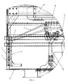
- Figure 1 is a lateral diagrammatic view of a mixer in which a section of the vertical wall has been removed to show the internal structure;
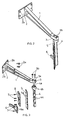
- Figure 2 is an axonometric view of the arm of the invention coupled with the blade-holding plate;
- Figure 3 is the exploded view of Figure 2.
- With reference to Fig. 1, the arm (1) of the invention operates in the tank (V) of a mixer for concrete, mortar and similar materials, of the type provided with a reduction gear (R) that actuates a crown wheel (P), which in turns drags into rotation two crosses (C)that support two sets of three mixing arms (B).
- In particular the arm (1) is radially fixed against the border of the crown wheel (P) by means of a suitable bracket (2) placed edgeways and welded at the rear end. Fixing is obtained by means of suitable bolts (2) capable of being screwed into the crown wheel (P) after passing through the through holes (2b) located on the bracket (2) of the arm (1).
- As mentioned above, the arm (1) is obtained with oxygen lance cutting technique (or casting) and has a basically triangular shape with a large central lightening cut. The front end (3) of the arm (1) has a basically parallelepiped shape and features two opposite through slots (3a) with vertical axis, preferably with semicircular profile.
- The front end (3) is also used to fix a blade-holding plate (4) in vertical position.
- The plate (4) has a basically T-shaped head, from which a pin (4a) centrally protrudes. Two threaded holes (4b) with vertical axis are located near the pin. The pin (4a) engages in a corresponding cavity (not shown in the enclosed figures) realised on the lower side of the front end (3) of the arm (1), while the two holes (4b) are capable of perfectly aligning with the slots (3a) of the front end (3) of the arm (1).
- The two parts (1, 4) are steadily fixed by means of suitable bolts (3b) with vertical axis, which are inserted in the slots (3a) from up downwards and engage with the threaded holes (4b) of the blade-holding plate (4). Before tightening, the bolts (3b) and the blade-holding plate (4) can be moved with respect to the front end (3) of the arm (1) thanks to the presence of the slots (3a).
- In the preferred version shown in the aforementioned figures, the blade-holding plate (4) obtained with oxygen lance cutting technique consists in a rod with quadrilateral cross-section, whose front end houses holes (4c) with horizontal axis used to fix two scraping blades (5, 6) with basically traditional structure, of which the upper blade (5) is composed of a sort of vertical blade and the lower blade (6) is fixed to the base of the blade (4) and is of scroll-shaped type.
- The two scraping blades (5, 6) are fixed to the bearing plate (4) by means of bolts (7) with horizontal axis that are introduced into the through holes (5a, 6a) and engage in the holes (4c) of the plate (4).
- Number (8) identifies a counter-plate with slots (8a) designed to engage with the front side of the vertical blade (5) to allow for adjusting the fixing position with respect to the support plate (4).
Claims (2)
- A support arm for a blade-holding plate used in mixers for concrete, mortar and similar materials, characterised in that its metal structure is obtained with oxygen lance cutting technique and provided with basically triangular shape with a large central lightening cut; it being provided that the arm (1), which is provided with a fixing bracket (2) placed edgeways and equipped with through holes (2b) with horizontal axis, has a basically parallelepiped front end (3) with two through slots (2b) with vertical axis for the up-down passage and transversal movement of bolts (3b) designed to engage into threaded holes (4b) vertically made on the top section of a blade-holding plate (4) obtained with oxygen lance cutting technique in contact with the lower side of the front end (3) of the arm (1).
- A support arm according to claim 1, characterised in that the front end (3) has a basically cylindrical cavity capable of housing a vertical pin (4a) that protrudes from the centre of the top section of the blade-holding plate (4), featuring a regular series of through holes with horizontal axis (4c) on the entire height used to fix two traditional scraping blades (5, 6) with holes with horizontal axis (5a, 6a) by means of bolts (7).
Applications Claiming Priority (2)
| Application Number | Priority Date | Filing Date | Title |
|---|---|---|---|
| ITMC20010044 | 2001-10-15 | ||
| IT2001MC000044U ITMC20010044U1 (en) | 2001-10-15 | 2001-10-15 | ARM FOR THE SUPPORT OF A SCRAPER-PAD HOLDER PLATE TO BE MOUNTED INSIDE THE MIXER FOR CONCRETE, MORTAR AND SIMILAR. |
Publications (1)
| Publication Number | Publication Date |
|---|---|
| EP1302238A1 true EP1302238A1 (en) | 2003-04-16 |
Family
ID=11443415
Family Applications (1)
| Application Number | Title | Priority Date | Filing Date |
|---|---|---|---|
| EP02425628A Withdrawn EP1302238A1 (en) | 2001-10-15 | 2002-10-14 | A support arm for a blade-holding plate used in mixers for concrete, mortar and similar materials |
Country Status (3)
| Country | Link |
|---|---|
| US (1) | US20030072210A1 (en) |
| EP (1) | EP1302238A1 (en) |
| IT (1) | ITMC20010044U1 (en) |
Cited By (1)
| Publication number | Priority date | Publication date | Assignee | Title |
|---|---|---|---|---|
| WO2010122092A3 (en) * | 2009-04-22 | 2011-01-13 | Richard Frisse Gmbh | Shearing/mixing tool |
Families Citing this family (1)
| Publication number | Priority date | Publication date | Assignee | Title |
|---|---|---|---|---|
| CN109482601A (en) * | 2018-09-28 | 2019-03-19 | 珠海仕高玛机械设备有限公司 | A kind of side blade construction facilitating installation and adjusting |
Citations (4)
| Publication number | Priority date | Publication date | Assignee | Title |
|---|---|---|---|---|
| CH429398A (en) * | 1965-04-06 | 1967-01-31 | Fischer Ag Georg | Mixing machine, especially for molding sand |
| US4183680A (en) * | 1977-07-27 | 1980-01-15 | Carpigiani Bruto Macchine Automatiche S.P.A. | Scraper and mixer element for ice cream making machines |
| DE8712698U1 (en) * | 1987-09-19 | 1987-11-19 | Fliegl, Josef, 8261 Kastl | Stirring device for agricultural mixers |
| DE29504562U1 (en) * | 1995-03-17 | 1995-05-11 | Teka Maschinenbau Gmbh | Vortex mixer for compulsory mixers |
Family Cites Families (6)
| Publication number | Priority date | Publication date | Assignee | Title |
|---|---|---|---|---|
| US493484A (en) * | 1893-03-14 | Thomas corscaden | ||
| US483834A (en) * | 1892-10-04 | Thomas corscxden | ||
| US624723A (en) * | 1899-05-09 | Bracket | ||
| US674663A (en) * | 1900-11-28 | 1901-05-21 | Paul Baran | Extension-bracket for eaves-troughs. |
| US3163132A (en) * | 1963-01-03 | 1964-12-29 | Illinois Tool Works | Support assembly for a perforated board |
| US3289988A (en) * | 1964-09-11 | 1966-12-06 | F Mckenney R F D George | Mailbox stand |
-
2001
- 2001-10-15 IT IT2001MC000044U patent/ITMC20010044U1/en unknown
-
2002
- 2002-10-11 US US10/270,834 patent/US20030072210A1/en not_active Abandoned
- 2002-10-14 EP EP02425628A patent/EP1302238A1/en not_active Withdrawn
Patent Citations (4)
| Publication number | Priority date | Publication date | Assignee | Title |
|---|---|---|---|---|
| CH429398A (en) * | 1965-04-06 | 1967-01-31 | Fischer Ag Georg | Mixing machine, especially for molding sand |
| US4183680A (en) * | 1977-07-27 | 1980-01-15 | Carpigiani Bruto Macchine Automatiche S.P.A. | Scraper and mixer element for ice cream making machines |
| DE8712698U1 (en) * | 1987-09-19 | 1987-11-19 | Fliegl, Josef, 8261 Kastl | Stirring device for agricultural mixers |
| DE29504562U1 (en) * | 1995-03-17 | 1995-05-11 | Teka Maschinenbau Gmbh | Vortex mixer for compulsory mixers |
Cited By (4)
| Publication number | Priority date | Publication date | Assignee | Title |
|---|---|---|---|---|
| WO2010122092A3 (en) * | 2009-04-22 | 2011-01-13 | Richard Frisse Gmbh | Shearing/mixing tool |
| CN102413912A (en) * | 2009-04-22 | 2012-04-11 | 理查德弗莱士有限公司 | Scratch Tool/Mix Tool |
| US8622607B2 (en) | 2009-04-22 | 2014-01-07 | Bühler AG | Shearing/mixing tool |
| CN105558214A (en) * | 2009-04-22 | 2016-05-11 | 理查德弗莱士有限公司 | Shearing/mixing tool |
Also Published As
| Publication number | Publication date |
|---|---|
| US20030072210A1 (en) | 2003-04-17 |
| ITMC20010044U1 (en) | 2003-04-15 |
Similar Documents
| Publication | Publication Date | Title |
|---|---|---|
| KR20060053194A (en) | Apparatus and method for making trench walls in the soil | |
| US20030072210A1 (en) | Support arm for a blade-holding plate used in mixers for concrete, mortar and similar materials | |
| CZ208495A3 (en) | Process and apparatus for material treatment | |
| CN209612772U (en) | A kind of painting stock dispersion equipment | |
| EP1302237B1 (en) | A light inexpensive cross for mixers of concrete, mortar and similar materials | |
| CN210752147U (en) | High-abrasion-resistance stirrer blade convenient for stirring | |
| JP3166999U (en) | Stir bar for stirrer | |
| CN209612707U (en) | A kind of water-based industrial paint stock stirring device | |
| CN216732406U (en) | Concrete mixing workstation convenient to remove | |
| CN110253754A (en) | A kind of combined type build cement mortar prepares stirring integrated machine | |
| JPS5946659B2 (en) | Impeller for stirrer | |
| CN210544658U (en) | Agitating unit is used in insulation coating production | |
| CN212385316U (en) | Fixture convenient for fixing and processing round pipe and square pipe for building | |
| US20170157619A1 (en) | Device for fixing and aligning cutter blades for a system for fine comminution | |
| CN208514746U (en) | A kind of concrete central mix plant of discharge port tilt adjustable | |
| CN220990564U (en) | Two-dimensional mixer with stirring scraper | |
| CN115070305A (en) | A welded platform for nozzle ring subassembly production | |
| CN219504083U (en) | A assembly fixture for installation of sorter intermediate section position | |
| CN220426661U (en) | Reinforcing bar shearing mechanism for construction | |
| RU2841814C1 (en) | Installation for creation of welded metal structure and method for creation of welded metal structure | |
| FR1465399A (en) | Assembly of scraping blades, especially for concrete mixers | |
| JP2004016864A (en) | Defoaming agitator | |
| CN218090387U (en) | Multifunctional noodle collector | |
| CN214079683U (en) | Semi-automatic small diameter pipe cutting and beveling device | |
| CN222609993U (en) | Ecological concrete raw and other materials allotment equipment |
Legal Events
| Date | Code | Title | Description |
|---|---|---|---|
| PUAI | Public reference made under article 153(3) epc to a published international application that has entered the european phase |
Free format text: ORIGINAL CODE: 0009012 |
|
| AK | Designated contracting states |
Designated state(s): AT BE BG CH CY CZ DE DK EE ES FI FR GB GR IE IT LI LU MC NL PT SE SK TR |
|
| AX | Request for extension of the european patent |
Extension state: AL LT LV MK RO SI |
|
| 17P | Request for examination filed |
Effective date: 20030929 |
|
| AKX | Designation fees paid |
Designated state(s): AT BE BG CH CY CZ DE DK EE ES FI FR GB GR IE IT LI LU MC NL PT SE SK TR |
|
| 17Q | First examination report despatched |
Effective date: 20040206 |
|
| GRAP | Despatch of communication of intention to grant a patent |
Free format text: ORIGINAL CODE: EPIDOSNIGR1 |
|
| STAA | Information on the status of an ep patent application or granted ep patent |
Free format text: STATUS: THE APPLICATION IS DEEMED TO BE WITHDRAWN |
|
| 18D | Application deemed to be withdrawn |
Effective date: 20050405 |