EP1302228B1 - Filtrationseinheit - Google Patents
Filtrationseinheit Download PDFInfo
- Publication number
- EP1302228B1 EP1302228B1 EP02405703A EP02405703A EP1302228B1 EP 1302228 B1 EP1302228 B1 EP 1302228B1 EP 02405703 A EP02405703 A EP 02405703A EP 02405703 A EP02405703 A EP 02405703A EP 1302228 B1 EP1302228 B1 EP 1302228B1
- Authority
- EP
- European Patent Office
- Prior art keywords
- filtrate
- filter elements
- filtration unit
- group
- filtration
- Prior art date
- Legal status (The legal status is an assumption and is not a legal conclusion. Google has not performed a legal analysis and makes no representation as to the accuracy of the status listed.)
- Expired - Lifetime
Links
Images


Classifications
-
- B—PERFORMING OPERATIONS; TRANSPORTING
- B01—PHYSICAL OR CHEMICAL PROCESSES OR APPARATUS IN GENERAL
- B01D—SEPARATION
- B01D63/00—Apparatus in general for separation processes using semi-permeable membranes
- B01D63/06—Tubular membrane modules
- B01D63/062—Tubular membrane modules with membranes on a surface of a support tube
- B01D63/063—Tubular membrane modules with membranes on a surface of a support tube on the inner surface thereof
-
- B—PERFORMING OPERATIONS; TRANSPORTING
- B01—PHYSICAL OR CHEMICAL PROCESSES OR APPARATUS IN GENERAL
- B01D—SEPARATION
- B01D29/00—Filters with filtering elements stationary during filtration, e.g. pressure or suction filters, not covered by groups B01D24/00 - B01D27/00; Filtering elements therefor
- B01D29/11—Filters with filtering elements stationary during filtration, e.g. pressure or suction filters, not covered by groups B01D24/00 - B01D27/00; Filtering elements therefor with bag, cage, hose, tube, sleeve or like filtering elements
- B01D29/117—Filters with filtering elements stationary during filtration, e.g. pressure or suction filters, not covered by groups B01D24/00 - B01D27/00; Filtering elements therefor with bag, cage, hose, tube, sleeve or like filtering elements arranged for outward flow filtration
- B01D29/118—Filters with filtering elements stationary during filtration, e.g. pressure or suction filters, not covered by groups B01D24/00 - B01D27/00; Filtering elements therefor with bag, cage, hose, tube, sleeve or like filtering elements arranged for outward flow filtration open-ended
-
- B—PERFORMING OPERATIONS; TRANSPORTING
- B01—PHYSICAL OR CHEMICAL PROCESSES OR APPARATUS IN GENERAL
- B01D—SEPARATION
- B01D29/00—Filters with filtering elements stationary during filtration, e.g. pressure or suction filters, not covered by groups B01D24/00 - B01D27/00; Filtering elements therefor
- B01D29/50—Filters with filtering elements stationary during filtration, e.g. pressure or suction filters, not covered by groups B01D24/00 - B01D27/00; Filtering elements therefor with multiple filtering elements, characterised by their mutual disposition
- B01D29/52—Filters with filtering elements stationary during filtration, e.g. pressure or suction filters, not covered by groups B01D24/00 - B01D27/00; Filtering elements therefor with multiple filtering elements, characterised by their mutual disposition in parallel connection
-
- B—PERFORMING OPERATIONS; TRANSPORTING
- B01—PHYSICAL OR CHEMICAL PROCESSES OR APPARATUS IN GENERAL
- B01D—SEPARATION
- B01D29/00—Filters with filtering elements stationary during filtration, e.g. pressure or suction filters, not covered by groups B01D24/00 - B01D27/00; Filtering elements therefor
- B01D29/50—Filters with filtering elements stationary during filtration, e.g. pressure or suction filters, not covered by groups B01D24/00 - B01D27/00; Filtering elements therefor with multiple filtering elements, characterised by their mutual disposition
- B01D29/56—Filters with filtering elements stationary during filtration, e.g. pressure or suction filters, not covered by groups B01D24/00 - B01D27/00; Filtering elements therefor with multiple filtering elements, characterised by their mutual disposition in series connection
-
- B—PERFORMING OPERATIONS; TRANSPORTING
- B01—PHYSICAL OR CHEMICAL PROCESSES OR APPARATUS IN GENERAL
- B01D—SEPARATION
- B01D63/00—Apparatus in general for separation processes using semi-permeable membranes
- B01D63/06—Tubular membrane modules
- B01D63/069—Tubular membrane modules comprising a bundle of tubular membranes
-
- B—PERFORMING OPERATIONS; TRANSPORTING
- B01—PHYSICAL OR CHEMICAL PROCESSES OR APPARATUS IN GENERAL
- B01D—SEPARATION
- B01D2201/00—Details relating to filtering apparatus
- B01D2201/04—Supports for the filtering elements
- B01D2201/043—Filter tubes connected to plates
- B01D2201/0453—Filter tubes connected to plates positioned between at least two plates
Definitions
- the invention relates to a method for filtering liquids, a filtration unit and a device for the filtration of liquids, comprising a filtration unit according to the invention with the features of the preamble of the independent claims.
- Filter modules with ceramic filter elements are known and are routinely used, for example, for the filtration of turbid liquids in the field of food technology or in the field of biotechnology.
- the method of crossflow filtration is used.
- unfiltered material is guided tangentially to the filter membrane and allows a simultaneous removal of the retained components of the membrane by the circulating unfiltrate.
- the Laid-open publication DE 198 46 041 describes a membrane module comprising a number of rod-shaped ceramic filter elements. The edges of the end faces of these filter elements are grasped into corresponding openings of a lid using sealing means. ,
- EP 208,450 describes a filtration device for beer filtration, which uses the crossflow filtration method.
- the filter elements are also made of ceramic material and have a plurality of through channels, through which the unfiltered material is passed.
- the filter modules described in the two documents have the disadvantage that the filter modules are only flowed through in each case in one direction by the unfiltered.
- a complex fluid guide which brings in particular in the case of a necessary change of a filter module or a filter element (ceramic rod) an increased workload with it.
- EP 0217568 discloses a filtration unit for cross-flow filtration of liquids with two groups of filter elements which can be arranged on concentric circles.
- the object of the present invention is to avoid the disadvantages of the known, in particular to provide a compact filtration unit, which allows a simplified handling while maintaining a high flow rate.
- the filter housing contains an even number, which is greater than two, to groups of ceramic filter elements.
- the filtration unit contains at least one means for reversing the flow direction of the unfiltrate on the side of the filter housing opposite the feed line and the outlet of the non-filtrate.
- the filtration unit on the side of the supply and the discharge additionally comprises a means for reversing the direction of flow.
- This means allows a reversal of the flow direction, so that within the filtration unit each consist of two independent areas with identical flow direction.
- the filtration unit for cross-flow filtration of liquids contains a filter housing for draining off the filtrate.
- This filter housing further contains rod-shaped, porous ceramic filter elements for the passage of the unfiltrate.
- the filter elements have axially parallel through holes whose inner sides are coated with a membrane material.
- These filter elements are characterized in that they are arranged in groups, wherein the number of groups is an even number greater than 2. These groups are connected to an arrangement for conducting the unfiltrate such that the unfiltered material in the first group of filter elements has an opposite flow direction as in the second group.
- This guide allows a space-saving installation of the filtration unit within a filtration device.
- the arrangement of the filter elements of each group takes place on several concentric circles, in each case relative to the center of the filtration unit.
- the filter elements of a first group are arranged opposite those of the second group closer to the center of the filtration unit.
- the center is to be understood as the longitudinal axis which is located in the center of the filter housing and in parallel alignment with the filter elements. At the position of this imaginary longitudinal axis and a filter element may be placed.
- Such an arrangement of the filter elements on concentric circles results in advantageous fluidic conditions.
- the individual filter elements are more uniformly flowed through or flowed through by the medium to be filtered, so that the membranes can be utilized more uniformly and the filtration performance can be increased.
- the number of circles on which the filter elements are positioned depends on the total number of filter elements as well as on the spatial dimensions of the filtration unit and can vary according to the respective requirements.
- the non-filtrate is fed to one side of the filter housing and drained on the same side. This type of arrangement also allows easy handling in terms of replacement of the filter housing.
- the supply line connects to the first group of filter elements of the filter housing and a discharge of the unfiltered material adjoins the other group of filter elements.
- the direction of flow of the unfiltrate of the supply line and the discharge is not fixed.
- the unfiltered material can also be led out of the filter elements via the supply line, as it can be led in via the discharge into the filter elements. Without this requirement of a predefined flow direction, the filtration unit can be used flexibly.
- a particular embodiment of the filtration unit is characterized in that the supply line and the discharge of the non-filtrate are sealed against each other flanged to the filter housing of the filter module.
- the mutual seal prevents short-circuit currents of the unfiltrate and a reduction in the flow rate of the unfiltered through the filter elements.
- a preferred embodiment of the filtration unit has an immediate, parallel adjacent arrangement of filter elements of at least one group. Such an arrangement allows an advantageous embodiment of the supply and discharge.
- the means for reversing the flow direction and / or the supply line and / or the discharge of the non-filtrate are firmly connected to the housing.
- the respective firm connection by gluing, welding, screwing, pressing etc. allows the user an easier installation of the filtration unit. At the same time a sufficient tightness is produced.
- the filtration unit preferably has at least one filtrate outlet opening and one respective vent opening for the filtrate and unfiltered space on the filter housing.
- a device for the filtration of liquids contains at least one filtration unit according to the invention and furthermore at least one pump for pumping the unfiltrate through the filtration unit.
- the use of several such filtration units within a device opens up the possibility of being able to make targeted adjustments to the throughput quantities.
- a pump in such a device an approximately constant flow of unfiltered material through the filtration units can be ensured without too great differences in the flow rate occurring within the system.
- the unfiltered material after step d) is subjected to at least one further step sequence c), d), c), d), through at least two further groups of filter elements within the filtration unit.
- a preferred form of the method is characterized by a serial or parallel arrangement of a plurality of filtration units.
- FIG. 1 An embodiment of the filtration unit is shown in FIG. 1.
- the filter housing 2 together with the filter elements 4, 4 'and the socket elements 9, 10 a closed space for the discharge of the filtrate.
- Suitable materials for the filter housing 2 are both stainless steel as well as normal steel with a corresponding plastic coating. Individual elements of the filter housing 2 can also be made of plastic.
- the Filtratauslassö réelleen also serve for vent 14 and for emptying the filtrate.
- the filtrate is discharged at least through one of the Filtratauslassö réelleen 3.
- Filtrate outlet also serves for venting respectively emptying the filtrate.
- the supply line 7 has a standard flange, which allows easy installation to a device for filtration.
- the unfiltered material is fed into the filter elements 4 '.
- the turbidity of the unfiltered material is retained by the filtering effect of the porous ceramic material on the surface and continuously removed by flowing unfiltrate.
- the non-filtrate exits on the opposite side of the feed line and is directed by the means for reversal 6 in the ceramic filter elements 4.
- the reversing means 6 can be used in various embodiments. For example, curved baffles or baffles may be integrated in this reversing means. Also can be attached to these reversing means a sealingly closable vent opening.
- the drain 8 may also have a standard flange that allows easy installation to a filtration device. However, the unfiltered material can also be passed through the discharge line 8 into the filtration unit and through the feed line 7 from the filtration unit.
- the filter elements as sold for example by the company aaflowsystems, consist of a coarsely porous support body on which one or more intermediate layers are applied.
- the last layer is a separating layer with precisely defined pore sizes.
- the material used for the carrier body and the intermediate and separating layers are aluminum oxide, titanium oxide, zirconium oxide and non-oxidic hard materials.
- the filter elements 4, 4 'in the form of ceramic rods are taken in the filter housing 2 as described below.
- the ceramic rods are inserted from above through the upper socket element 10.
- the holes in the upper socket element 10 are therefore larger than the maximum outer diameter of the ceramic rods.
- the holes are adapted to the ground diameter of the ceramic rod ends.
- the seal in the lower socket member 9 is made with a standard double 0-ring seal 11.
- the seal is effected by means of a squeezed together by a clamping plate 13 O-ring 11. This is at the same time a seal between the upper socket member 10 and Clamp 13 achieved.
- the squeezing of the seal also increases the radial force on the ceramic rod (filter element 4, 4 ') and prevents smooth movement of the filter element 4, 4' in the axial direction, as it may be possible in particular when starting the system.
- a displacement of the filter elements 4, 4 'in the longitudinal direction is limited by double-sided end stops 12.
- the end stops are damped with a rubber seal.
- the seals are made of acrylonitrile butadiene rubber (NBR), ethylene propylene rubber (EPDM), fluorinated rubber (FKM), chlorobutadiene rubber (CR), styrene butadiene rubber (SBR), silicone -Rubber (VMQ), fluorosilicone rubber (FVMQ) or Viton.
- NBR acrylonitrile butadiene rubber
- EPDM ethylene propylene rubber
- FKM fluorinated rubber
- CR chlorobutadiene rubber
- SBR styrene butadiene rubber
- VMQ silicone -Rubber
- FVMQ fluorosilicone rubber
- the supply line 7 and the discharge line 8 can also be designed so that a complete emptying of the lower chamber or the supply line or discharge can be ensured.
- a cross section through an exemplary filtration unit 1, as shown in FIG. 2, illustrates the advantage of an ordered arrangement of the filter elements 4, 4 '.
- the number of filter elements 4, 4 ', each having an identical cross-sectional size, is divided into two groups 5, 5' each having the same number of filter elements 4, 4 '.
- the filter elements 4, 4 'in the described embodiment are arranged on concentric circles around the center of the filtration unit 1.
- the filter elements 4 are analogously found on the two outer arrangement rings and form the second group 5. This manner of arrangement allows a simple connection of the supply line 7 and the discharge line 8 to the filter housing 2.
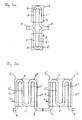
- FIG. 3a The possibility of a parallel arrangement of two filtration units 1, 1 'according to the invention is shown in FIG. 3a.
- Both filtration units 1, 1 ' are connected via a common supply line 7 for the unfiltered material.
- the unfiltered stream After flowing through a first group 5 of filter elements the unfiltered stream is deflected in the interior of the filtration units 1 and 1 'by the reversal 6 in its direction and flows through a second group 5' of filter elements.
- the remaining unfiltered material is combined from the respective filtration unit 1, 1 'in the common discharge 8 and can be subjected to further filtration.
- the recovered filtrate is removed from the filtration units 1, 1 'via the filtrate outlet 3.
- FIG. 3b A further possibility for the arrangement of filtration unit 1, 1 'according to the invention is shown schematically in FIG. 3b.
- the filtration units 1, 1 ' are arranged in series.
- the filtration unit 1, 1 ' designed so that the unfiltrate within the filtration unit 1, 1' is repeatedly deflected.
- the unfiltered material is passed through the supply line 7 into the filtration unit 1, flows through the first group 5 of filter elements and is directed by the reversal 6 into the second group 5 'of filter elements.
- the reversal 6 ' the unfiltered material is in turn deflected and flows through a third group 5' 'of filter elements.
- the direction of flow of the unfiltered material within the third groups 5 "of filter elements is identical to the direction of flow within the first group 5. Due to the inversion 6", the unfiltered material from the third group 5 "is diverted into the fourth group 5 '" by filter elements. Thus, the flow direction of the unfiltered material within the fourth groups 5 “'of filter elements is in turn identical to the direction of flow within the second group 5' After the fourth group 5" 'of filter elements, the remaining non-filtrate from the filtration unit 1 is led away through the outlet 8 and passes through the corresponding supply line 7 in the filtration unit 1 '.
- the filtration unit 1 ' is constructed analogously to the filtration unit 1. The recovered filtrate is removed from the filtration units 1, 1 'via the filtrate outlet 3. Of course, more than two such filtration units 1, 1 'can be arranged in series.
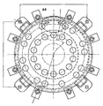
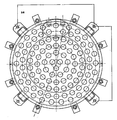
- FIGS. 4a and 4b Further possibilities of arranging the groups 5, 5 'of filter elements 4, 4' are shown in FIGS. 4a and 4b, in analogy to FIG. 2.
- the two groups 5 and 5 ' are in each case a concentric circle around the center of the filtration unit 1 is arranged.
- This arrangement is particularly advantageous for a filtration unit 1 with a small number of filter elements 4, 4 'while maintaining the fluidically advantageous conditions.
- 4 ' is an arrangement according to the figure 4b suitable.
- the filter elements 4 'of the group 5' are arranged on four concentric circles around the center; the filter elements 4 of the group 5 can be arranged on two, in the radially outer region on two concentric circles around the center.
Landscapes
- Chemical & Material Sciences (AREA)
- Chemical Kinetics & Catalysis (AREA)
- Separation Using Semi-Permeable Membranes (AREA)
- Filtration Of Liquid (AREA)
- Filtering Materials (AREA)
Description
- Die Erfindung betrifft eine Methode zum Filtrieren von Flüssigkeiten, eine Filtrationseinheit und eine Vorrichtung zur Filtration von Flüssigkeiten, enthaltend eine erfindungsgemässe Filtrationseinheit mit den Merkmalen des Oberbegriffs der unabhängigen Patentansprüche.
- Filtermodule mit keramischen Filterelementen sind bekannt und werden beispielsweise für die Filtration von trüben Flüssigkeiten im Bereich der Lebensmitteltechnologie bzw. im biotechnologischen Bereich routinemässig eingesetzt. Zur Erzielung von hohen Durchsatzraten wird dabei die Methode der Crossflow-Filtration angewendet. Hierbei wird Unfiltrat tangential zur Filtermembran geführt und ermöglicht eine gleichzeitige Entfernung der von der Membran zurückgehaltenen Bestandteile durch das im Kreislauf bewegte Unfiltrat.
- Die
Offenlegungsschrift DE 198 46 041 beschreibt ein Membranmodul, das eine Anzahl von stabförmigen, keramischen Filterelementen aufweist. Die Ränder der Stirnseiten dieser Filterelemente werden unter Verwendung von Dichtungsmitteln in entsprechende Öffnungen eines Deckels gefasst. . -
EP 208 450 - Die in den beiden Dokumenten beschriebenen Filtermodule weisen jedoch den Nachteil auf, dass die Filtermodule jeweils nur in einer Richtung vom Unfiltrat durchströmt werden. Bei der Verwendung von mehreren dieser Filtermodulen in einer Filtrationsvorrichtung kommt es daher zu einer komplexen Flüssigkeitsführung, die insbesondere im Fall eines notwendigen Wechsels eines Filtermoduls oder eines Filterelementes (Keramikstab) einen erhöhten Arbeitsaufwand mit sich bringt.
- D1 (
EP 0217568 ) offenbart eine Filtrationseinheit zur Crossflowfiltration von Flüssigkeiten mit zwei Gruppen von Filterelementen, die auf konzentrischen Kreisen angeordnet sein können. - Die Aufgabe der vorliegenden Erfindung ist es, die Nachteile des Bekannten zu vermeiden, insbesondere eine kompakte Filtrationseinheit zu schaffen, die eine vereinfachte Handhabung bei gleichzeitiger Erhaltung einer hohen Durchflussrate erlaubt.
- Die Erfindung löst diese Aufgabe entsprechend den Merkmalen des kennzeichnenden Teils der Ansprüche1 und 9.
- Gemäß der Erfindung enthält das Filtergehäuse eine geradzahlige Anzahl, die grösser ist als zwei, an Gruppen von keramischen Filterelementen.
- Gemäß der Erfindung enthält die Filtrationseinheit auf der der Zuleitung und der Ableitung des Unfiltrats gegenüberliegenden Seite des Filtergehäuses mindestens ein Mittel zur Umkehrung der Durchflussrichtung des Unfiltrats.
- Gemäß der Erfindung weist die Filtrationseinheit auf der Seite der Zuleitung und der Ableitung zusätzlich ein Mittel zur Umkehrung der Durchflussrichtung auf. Dieses Mittel erlaubt eine Umkehrung der Durchflussrichtung, so dass innerhalb der Filtrationseinheit jeweils zwei unabhängige Bereiche mit identischer Durchflussrichtung bestehen.
- Die Filtrationseinheit zur Crossflow-Filtration von Flüssigkeiten enthält ein Filtergehäuse zum Ableiten des Filtrates. Dieses Filtergehäuse enthält weiterhin stabförmige, poröse keramische Filterelemente zur Durchleitung des Unfiltrats. Die Filterelemente weisen achsparallele Durchgangsbohrungen auf, deren Innenseiten mit einem Membranmaterial beschichtet sind. Diese Filterelemente zeichnen sich dadurch aus, dass sie in Gruppen angeordnet sind, wobei die Anzahl der Gruppen eine gerade Zahl größer als 2 ist. Diese Gruppen werden mit einer Anordnung zum Leiten des Unfiltrats derart verbunden, dass das Unfiltrat in der ersten Gruppe von Filterelementen eine entgegengesetzte Strömungsrichtung wie in der zweiten Gruppe aufweist. Diese Führungsweise ermöglicht eine raumsparende Installation der Filtrationseinheit innerhalb einer Filtrationsvorrichtung. Die Anordnung der Filterelemente einer jeden Gruppe erfolgt auf mehreren konzentrischen Kreisen, jeweils bezogen zum Mittelpunkt der Filtrationseinheit. Die Filterelemente einer ersten Gruppe sind gegenüber denen der zweiten Gruppe näher zum Mittelpunkt der Filtrationseinheit angeordnet. Als Mittelpunkt ist diejenige Längsachse zu verstehen, die sich im Zentrum des Filtergehäuses und in paralleler Ausrichtung zu den Filterelementen befindet. An der Position dieser imaginären Längsachse kann auch ein Filterelement platziert sein. Eine solche Anordnung der Filterelemente auf konzentrischen Kreisen ergibt vorteilhafte strömungstechnische Verhältnisse. Die einzelnen Filterelemente werden gleichmässiger vom zu filtrierenden Medium angeströmt bzw. durchströmt, womit die Membranen gleichmässiger ausgenutzt werden können und die Filtrationsleistung gesteigert werden kann. Die Anzahl der Kreise, auf denen die Filterelemente positioniert werden, ist jeweils von der Gesamtzahl der Filterelemente sowie von den räumlichen Dimensionen der Filtrationseinheit abhängig und kann entsprechend den jeweiligen Erfordernissen variieren.
- In einer bevorzugten Ausführungsform wird das Unfiltrat auf einer Seite des Filtergehäuses zugeleitet und auf derselben Seite abgeleitet. Diese Art der Anordnung erlaubt ebenfalls eine einfache Handhabung im Hinblick auf einen Austausch des Filtergehäuses.
- In einer weiteren Ausführungsform der Filtrationseinheit schliesst die Zuleitung die erste Gruppe der Filterelemente des Filtergehäuses an und eine Ableitung des Unfiltrats schliesst an die andere Gruppe der Filterelemente an. Diese Ausführung erlaubt eine direkte Verbindung des Filtergehäuses an die Zuleitung und Ableitung, ohne dass weitere Mittel zur Verknüpfung erforderlich sind.
- Die Fliessrichtung des Unfiltrats der Zuleitung und der Ableitung ist nicht festgelegt. Das Unfiltrat kann ebenso über die Zuleitung aus den Filterelementen herausgeleitet werden, wie es über die Ableitung in die Filterelemente hineingeleitet werden kann. Ohne diese Notwendigkeit einer vordefinierten Fliessrichtung ist die Filtrationseinheit flexibel einsetzbar.
- Eine besondere Ausführungsform der Filtrationseinheit zeichnet sich dadurch aus, dass die Zuleitung und die Ableitung des Unfiltrats gegeneinander abgedichtet an das Filtergehäuses des Filtermoduls angeflanscht sind. Die gegenseitige Abdichtung verhindert Kurzschlussströme des Unfiltrats und eine Reduzierung der Durchsatzmenge des Unfiltrats durch die Filterelemente.
- Ebenfalls eine bevorzugte Ausführungsform der Filtrationseinheit weist eine unmittelbare, parallel nebeneinander liegende Anordnung von Filterelementen wenigstens einer Gruppe auf. Eine derartige Anordnung erlaubt eine vorteilhafte Ausgestaltung der Zuleitung und Ableitung.
- In einer bevorzugten Form der Filtrationseinheit sind das Mittel zur Umkehrung der Durchflussrichtung und/oder die Zuleitung und/oder die Ableitung des Unfiltrats fest mit dem Gehäuse verbunden. Die jeweilige feste Verbindung mittels Kleben, Schweissen, Verschrauben, Verpressen etc. ermöglicht dem Anwender eine einfachere Installation der Filtrationseinheit. Gleichzeitig wird eine ausreichende Dichtigkeit hergestellt.
- Weiterhin bevorzugt weist die Filtrationseinheit mindestens eine Filtratauslassöffnung sowie je eine Entlüftungsöffnung für den Filtrat- und Unfiltratraum am Filtergehäuse auf.
- Eine Vorrichtung zur Filtration von Flüssigkeiten enthält mindestens eine erfindungsgemässen Filtrationseinheit und weiterhin wenigstens eine Pumpe zum Pumpen des Unfiltrats durch die Filtrationseinheit. Der Einsatz mehrerer solcher Filtrationseinheiten innerhalb einer Vorrichtung eröffnet die Möglichkeit, gezielt eine Anpassung der Durchsatzmengen vornehmen zu können. Mittels einer Pumpe in einer solchen Vorrichtung kann ein annähernd konstanter Durchfluss an Unfiltrat durch die Filtrationseinheiten sichergestellt werden, ohne dass zu grosse Unterschiede der Fliessgeschwindigkeit innerhalb des Systems auftreten.
- Ein Verfahren zur Filtration von Flüssigkeiten in einer Filtrationseinheit gemäss der Erfindung zeichnet sich durch die folgende Schritte aus:
- a) Zuführung des Unfiltrats durch ein Zuleitungselement zu einem Filtermodul mit wenigstens zwei Filterelementen;
- b) Durchführung des Unfiltrats durch mindestens eine Gruppe von Filterelementen;
- c) Umkehrung der Fliessrichtung des Unfiltrats mit wenigstens einem Mittel zur Umkehrung der Fliessrichtung;
- d) Durchführung des Unfiltrats durch die zweite Gruppe von Filterelementen, die nicht für Schritt b) eingesetzt werden, mit einer der Fliessrichtung des Schrittes b) entgegengesetzten Fliessrichtung; und
- e) Ausleitung des nicht filtrierten Unfiltrats durch eine Ableitung mit einer von der Zuleitungsflüssigkeit getrennten Flüssigkeitsführung.
- In einer weiteren Ausführungsform des Verfahrens wird das Unfiltrat nach dem Schritt d) wenigstens einer weiteren Schrittfolge c), d), c), d), durch wenigstens zwei weitere Gruppen von Filterelementen innerhalb der Filtrationseinheit unterworfen.
- Eine bevorzugte Form des Verfahrens zeichnet sich durch eine serielle oder parallele Anordnung mehrerer Filtrationseinheiten aus.
- Die Erfindung wird im folgenden an einem Ausführungsbeispiel und anhand der Zeichnungen näher erläutert. Es zeigen
- Fig. 1
- einen Längsschnitt durch eine Filtrationseinheit;
- Fig. 2
- einen Querschnitt einer Filtrationseinheit;
- Fig. 3
- eine schematische Darstellung zweier erfindungsgemässer Filtrationseinheiten in
- (a)
- paralleler Anordnung; und
- (b)
- serieller Anordnung, wobei hier innerhalb der Filtrationseinheit eine Mehrfachumlenkung erfolgt;
- Fig. 4 (a) und (b)
- jeweils einen Querschnitt einer weiteren Ausführungsform einer Filtrationseinheit.
- Ein Ausführungsbeispiel der Filtrationseinheit zeigt Fig. 1. Das Filtergehäuse 2 bildet zusammen mit den Filterelementen 4, 4' und den Fassungselementen 9, 10 einen abgeschlossenen Raum zur Ableitung des Filtrats. Geeignete Materialien für das Filtergehäuse 2 sind sowohl rostfreier Edelstahl wie auch Normalstahl mit einer entsprechenden Kunststoffbeschichtung. Einzelne Elemente des Filtergehäuses 2 können auch in Kunststoff ausgeführt sein. Die Filtratauslassöffnungen dienen gleichzeitig auch zur Entlüftung 14 bzw. zur Entleerung des Filtratraumes. Das Filtrat wird mindestens durch eine der Filtratauslassöffnungen 3 abgeführt. Filtratauslauföffnung dient gleichzeitig auch zur Entlüftung respektive Entleerung des Filtratraumes. Durch die Zuleitung 7 wird das Unfiltrat in die Filtrationseinheit 1 geleitet. Die Zuleitung 7 weist einen genormten Flansch auf, der eine einfache Installation an eine Vorrichtung zur Filtration erlaubt. Von der Zuleitung 7 wird das Unfiltrat in die Filterelemente 4' geführt. In den keramischen Filterelementen 4' werden die Trübungsstoffe des Unfiltrat durch die Filterwirkung des porösen Keramikmaterials an der Oberfläche zurückgehalten und durch nachfliessendes Unfiltrat kontinuierlich entfernt. Nach dem Durchströmen der keramischen Filterelemente 4' tritt das Unfiltrat auf der der Zuleitung entgegengesetzten Seite aus und wird durch das Mittel zur Umkehrung 6 in die keramischen Filterelemente 4 gelenkt. Das Umkehrungsmittel 6 kann in verschiedensten Ausführungsformen eingesetzt werden. So können beispielsweise gekrümmte Prallflächen oder Leitwände in dieses Umkehrungsmittel integriert sein. Ebenfalls kann an diesen Umkehrungsmitteln eine dichtend verschliessbare Entlüftungsöffnung angebracht sein. Nach dem Strömen des Unfiltrats durch das keramische Filterelement 4 und der darin stattfindenden Filtrationsvorgänge wird das verbleibende Unfiltrat durch die Ableitung 8 aus der Filtrationseinheit geführt. Die Ableitung 8 kann ebenfalls einen genormten Flansch aufweisen, der eine einfache Installation an eine Filtrationsvorrichtung ermöglicht. Das Unfiltrat kann jedoch auch durch die Ableitung 8 in die Filtrationseinheit und durch die Zuleitung 7 aus der Filtrationseinheit geführt werden.
- Die Filterelemente, wie sie beispielsweise durch die Firma aaflowsystems vertrieben werden, bestehen aus einem grob porösen Trägerkörper auf den eine oder mehrere Zwischenschichten aufgebracht sind. Als letzte Schicht wird eine Trennschicht mit genau definierten Porengrössen appliziert. Als Material für den Trägerkörper sowie die Zwischen- und Trennschichten finden Aluminiumoxid, Titanoxid, Zirkonoxid und nicht oxidische Hartstoffe Verwendung.
- Die Filterelemente 4, 4' in Form von Keramikstäben sind wie im Folgenden beschrieben im Filtergehäuse 2 gefasst. Die Keramikstäbe werden von oben durch das obere Fassungselement 10 eingeschoben. Die Bohrungen in dem oberen Fassungselement 10 sind daher grösser als der maximale Aussendurchmesser der Keramikstäbe. In dem unteren Fassungselement 9 sind die Bohrungen dem angeschliffenen Durchmesser der Keramikstabenden angepasst. Die Dichtung in dem unteren Fassungselement 9 erfolgt mit einer standardmässigen doppelten 0-Ring-Abdichtung 11. Im oberen Fassungselement 10 erfolgt die Abdichtung mittels eines durch eine Klemmplatte 13 zusammengequetschen O-Ringes 11. Hierdurch wird zugleich eine Dichtung zwischen dem oberen Fassungselement 10 und der Klemmplatte 13 erzielt. Das Zusammenquetschen der Dichtung erhöht zudem auch die radiale Kraft auf den Keramikstab (Filterelement 4, 4') und verhindert ein leichtgängiges Bewegen des Filterelementes 4, 4' in axialer Richtung, wie es insbesondere beim Anfahren der Anlage möglich sein kann. Ein Verschieben der Filterelemente 4, 4' in Längsrichtung wird durch beidseitige Endanschläge 12 begrenzt. Zum Schutze der Aufschlag empfindlichen Kanten der Keramikstäbe (Filterelemente 4, 4') sind die Endanschläge mit einer Gummidichtung gedämpft. Entsprechend dem jeweiligen Einsatzbereich sind die Dichtungen aus Acrylnitril-Butadien-Kautschuk (NBR), Ethylen-Propylen-Kautschuk (EPDM), Fluor-Kautschuk (FKM), Chlorbutadien-Kautschuk (CR), Styrol-Butadien-Kautschuk (SBR), Silikon-Kautschuk (VMQ), Fluorsilikon-Kautschuk (FVMQ) oder Viton ausgeführt.
- Die Zuleitung 7 und die Ableitung 8 können allerdings auch so ausgeführt sein, dass eine restlose Entleerung der unteren Kammer bzw. der Zuleitung oder Ableitung gewährleistet werden kann.
- Ein Querschnitt durch eine beispielhafte Filtrationseinheit 1, wie sie Fig. 2 zeigt, verdeutlicht den Vorteil einer geordneten Anordnung der Filterelemente 4, 4'. Die Anzahl von Filterelementen 4, 4' mit jeweils identischer Querschnittsgrösse wird in zwei Gruppen 5, 5' mit jeweils gleicher Anzahl an Filterelemente 4, 4' aufgeteilt. Wie aus der Fig. 2 zu erkennen ist, sind die Filterelemente 4, 4' in der beschriebenen Ausführungsform auf jeweils konzentrischen Kreisen um den Mittelpunkt der Filtrationseinheit 1 angeordnet. Deutlich erkennbar bilden die Filterelemente 4' auf den beiden inneren Anordnungskreisen die Gruppe 5'. Analog finden sich die Filterelemente 4 auf den beiden äusseren Anordnungsringen und bilden die zweite Gruppe 5. Diese Art und Weise der Anordnung ermöglicht eine einfache Anschliessung der Zuleitung 7 bzw. der Ableitung 8 an das Filtergehäuse 2. Das aufgrund der Filterwirkung der porösen keramischen Filterelemente 4, 4' gebildete Filtrat wird durch die Filtratauslassöffnungen 3 aus dem Filtergehäuse 2 herausgeführt.
Abweichend von in Figur 2 dargestellten Anordnung kann sich die Anzahl der Filterelemente 4 bzw. 4' in den Gruppen 5, 5' dann unterscheiden, wenn die Filterelemente 4 eine andere Querschnittsgrösse aufweisen als die Filterelemente 4'. Bei der Auswahl der Filterelemente 4 bzw. 4' ist dann aber zu beachten, dass in der jeweiligen Summe der Strömungswiderstand bzw. das Durchströmungsvolumen der Filterelemente 4 bzw. 4' einen identischen Wert aufweist. Eine solche Auswahl unterschiedlicher Querschnittsgrössen der Filterelemente 4, 4' kann sich vorteilhaft auf die räumliche Ausgestaltung der Filtrationseinheit 1 auswirken. - Die Möglichkeit einer parallelen Anordnung zweier erfindungsgemässen Filtrationseinheiten 1, 1' zeigt Figur 3a. Beide Filtrationseinheiten 1, 1' werden über eine gemeinsame Zuleitung 7 für das Unfiltrat angeschlossen. Nach dem Durchströmen einer ersten Gruppe 5 von Filterelementen wird der Unfiltratstrom im Innern der Filtrationseinheiten 1 bzw. 1' durch die Umkehrung 6 in seiner Richtung umgelenkt und fliesst durch eine zweite Gruppe 5' von Filterelementen. Das verbleibende Unfiltrat wird aus der jeweiligen Filtrationseinheit 1, 1' in der gemeinsamen Ableitung 8 zusammengeführt und kann einer weiteren Filtration unterworfen werden. Das gewonnene Filtrat wird aus den Filtrationseinheiten 1, 1' über den Filtratauslass 3 entnommen.
- Eine weitere Möglichkeit zur Anordnung von erfindungsgemässen Filtrationseinheit 1, 1' ist schematisch in Figur 3b dargestellt. In dieser Ausführungsform sind die Filtrationseinheiten 1, 1' in Serie angeordnet. Zusätzlich ist in der Figur 3b die Filtrationseinheit 1, 1' so ausgestaltet, dass der Unfiltratstrom innerhalb der Filtrationseinheit 1, 1' mehrfach umgelenkt wird. Das Unfiltrat wird durch die Zuleitung 7 in die Filtrationseinheit 1 geleitet, durchfliesst die erste Gruppe 5 von Filterelementen und wird durch die Umkehrung 6 in die zweite Gruppe 5' von Filterelementen gelenkt. Durch die Umkehrung 6' wird das Unfiltrat wiederum umgelenkt und durchströmt eine dritte Gruppe 5'' von Filterelementen. Die Fliessrichtung des Unfiltrats innerhalb der dritten Gruppen 5" von Filterelementen ist identisch mit der Fliessrichtung innerhalb der erste Gruppe 5. Aufgrund der Umkehrung 6'' wird das Unfiltrat aus der dritten Gruppe 5" in die vierte Gruppe 5''' von Filterelementen umgelenkt. Damit ist die Fliessrichtung des Unfiltrats innerhalb der vierten Gruppen 5"' von Filterelementen wiederum identisch mit der Fliessrichtung innerhalb der zweiten Gruppe 5'. Nach der vierten Gruppe 5"' von Filterelementen wird das verbleibende Unfiltrat aus der Filtrationseinheit 1 durch die Ableitung 8 weggeführt und gelangt über die entsprechende Zuleitung 7 in die Filtrationseinheit 1'. Die Filtrationseinheit 1' ist analog der Filtrationseinheit 1 aufgebaut. Das gewonnene Filtrat wird aus den Filtrationseinheiten 1, 1' über den Filtratauslass 3 entnommen. Selbstverständlich können auch mehr als zwei solcher Filtrationseinheiten 1, 1' in Serie angeordnet werden.
- Weitere Möglichkeiten der Anordnung der Gruppen 5, 5' von Filterelementen 4, 4' sind in den Figuren 4a und 4b dargestellt, in Analogie zur Figur 2. In Figur 4a sind die beiden Gruppen 5 und 5' auf jeweils einem konzentrischen Kreis um den Mittelpunkt der Filtrationseinheit 1 angeordnet. Diese Anordnung ist insbesondere für eine Filtrationseinheit 1 mit einer kleinen Anzahl an Filterelementen 4, 4' unter Erhalt der strömungstechnisch vorteilhaften Verhältnisse vorteilhaft. Für eine Filtrationseinheit 1 mit einer grossen Zahl an Filterelementen 4, 4' ist eine Anordnung entsprechend der Figur 4b geeignet. Die Filterelemente 4' der Gruppe 5' befinden sich auf vier konzentrischen Kreisen um den Mittelpunkt angeordnet; die Filterelemente 4 der Gruppe 5 können auf zwei, im radial äusseren Bereich auf zwei konzentrischen Kreisen um den Mittelpunkt angeordnet werden.
Claims (12)
- Filtrationseinheit (1) zur Crossflow-Filtration von Flüssigkeiten enthaltend ein Filtergehäuse. (2) zum Ableiten von Filtrat, welches Filtergehäuse (2) wenigstens zwei rohrförmige, keramische Filterelemente (4, 4') zur Durchleitung des Unfiltrats enthält, wobei die Filterelemente (4, 4') in wenigstens zwei Gruppen (5, 5') angeordnet sind und die Filterelemente. (4, 4') jeder Gruppe derart mit einer Anordnung zum Leiten des Unfiltrats verbunden sind, dass das Unfiltrat in der ersten Gruppe (5) von Filterelementen (4) in einer Strömungsrichtung und in der zweiten Gruppe (5') in der entgegengesetzten Richtung strömt, die Filterelemente (4') der ersten Gruppe (5') auf ein oder mehreren, insbesondere auf zwei inneren, konzentrischen Kreisen um den Mittelpunkt der Filtrationseihheit (1) angeordnet sind und die Filterelemente (4) der zweiten Gruppe (5) auf einen oder mehreren äusseren, konzentrischen Kreisen um den Mittelpunkt der Filtrationseinheit (1) angeordnet sind, dadurch gekennzeichnet, dass das Filtergehäuse (2) eine grössere geradzahlige Anzahl als zwei an Gruppen (5, 5') von keramischen Filterelementen (4, 4') enthält,
die der Zuleitung (7) und Ableitung (8) gegenüberliegenden Seite des Filtergehäuses (2) mindestens ein Mittel zur Umkehrung (6) der Durchflussrichtung des Unfiltrats enthält und
auf der Seite der Zuleitung (7) und Ableitung (8) zusätzlich mindestens ein Mittel zur Umkehrung der Durchflussrichtung angeordnet ist. - Filtrationseinheit (1) nach Anspruch 1, dadurch gekennzeichnet, dass das Unfiltrat auf einer Seite des Filtergehäuses (2) zugeleitet und auf derselben Seite abgeleitet wird.
- Filtrationseinheit (1) nach einem der Ansprüche 1 oder 2, dadurch gekennzeichnet, dass eine Zuleitung (7) die erste Gruppe (5') der Filterelemente (4') des Filtergehäuses anschliesst und dass eine Ableitung (8) die andere Gruppe (5) der Filterelemente (4) des Filtergehäuses (2) anschliesst.
- Filtrationseinheit (1) nach einem der Ansprüche 1 bis 3, dadurch gekennzeichnet, dass die Zuleitung (7) und die Ableitung (8) des Unfiltrats gegeneinander abgedichtet an das Filtergehäuse (2) des Filtrationseinheit (1) angeflanscht sind.
- Filtrationseinheit (1) nach einem der Ansprüche 1 bis 4, dadurch gekennzeichnet, dass die keramischen Filterelemente (4, 4') wenigstens einer Gruppe (5, 5') unmittelbar parallel nebeneinander angeordnet sind.
- Filtrationseinheit (1) nach einem der Ansprüche 1 bis 5, dadurch gekennzeichnet, dass das Mittel zur Umkehrung der Durchflussrichtung und/oder die Zuleitung (7) und/oder die Ableitung (8) des Unfiltrats fest mit dem Gehäuse (2) verbunden sind.
- Filtrationseinheit (1) nach einem der Ansprüche 1 bis 6, dadurch gekennzeichnet, dass das Filtergehäuse (2) mindestens eine Filtratauslassöffnung (3) aufweist.
- Vorrichtung zur Filtration von Flüssigkeiten enthaltend mindestens eine Filtrationseinheit (1) nach einem der Ansprüche 1 bis 7 und wenigstens eine Pumpe zum Pumpen des Unfiltrats durch die Filtrationseinheit (1).
- Verfahren zur Filtration von trüben Flüssigkeiten im Bereich der Lebensmitteltechnologie bzw. im biotechnologischen Bereich in einer Filtrationseinheit (1) nach einem der Ansprüche 1 bis 7, gekennzeichnet durch die Schritte:a) Zuführung des Unfiltrat durch ein Zuleitungselement (7) zu einem Filtergehäuse mit wenigstens zwei keramischen Filterelementen (4, 4');b) Durchführung des Unfiltrats durch mindestens eine Gruppe (5, 5') von keramischen Filterelementen (4, 4');c) Umkehrung der Fliessrichtung des Unfiltrats mit mindestens einem Mittel zur Umkehrung (6) der Fliessrichtung;d) Durchführung des Unfiltrats durch die zweite Gruppe (5, 5') von keramischen Filterelementen (4, 4'), die nicht für Schritt b) eingesetzt werden, mit einer der Fliessrichtung des Schrittes b) entgegengesetzten Fliessrichtung; unde) Ausleitung des nicht filtrierten Unfiltrats durch eine Ableitung (8) mit einer von der Zuleitung (7) flüssigkeitsdicht abgetrennten Flüssigkeitsführung.
- Verfahren zur Filtration von Flüssigkeiten nach Anspruch 9, dadurch gekennzeichnet, dass mehrere Filtrationseinheiten (1) seriell oder parallel angeordnet sind.
- Verfahren zur Filtration von Flüssigkeiten nach einem der Ansprüche 9. oder 10, dadurch gekennzeichnet, dass das Unfiltrat nach dem Schritt d) wenigstens einer weiteren Schrittfolge c), b), c) und d) durch wenigstens zwei weitere Gruppen (5, 5') von Filterelementen (4, 4') innerhalb der Filtrationseinheit (1) geführt wird.
- Verfahren zur Filtration von Flüssigkeiten nach einem der Ansprüche 9 bis 11, dadurch gekennzeichnet, dass das Unfiltrat durch die Ableitung (7) zugeführt wird und durch die Zuleitung (7) abgeführt wird.
Priority Applications (1)
| Application Number | Priority Date | Filing Date | Title |
|---|---|---|---|
| EP02405703A EP1302228B1 (de) | 2001-10-11 | 2002-08-16 | Filtrationseinheit |
Applications Claiming Priority (3)
| Application Number | Priority Date | Filing Date | Title |
|---|---|---|---|
| EP01810992A EP1302227A1 (de) | 2001-10-11 | 2001-10-11 | Filtrationseinheit |
| EP01810992 | 2001-10-11 | ||
| EP02405703A EP1302228B1 (de) | 2001-10-11 | 2002-08-16 | Filtrationseinheit |
Publications (2)
| Publication Number | Publication Date |
|---|---|
| EP1302228A1 EP1302228A1 (de) | 2003-04-16 |
| EP1302228B1 true EP1302228B1 (de) | 2007-09-12 |
Family
ID=26077425
Family Applications (1)
| Application Number | Title | Priority Date | Filing Date |
|---|---|---|---|
| EP02405703A Expired - Lifetime EP1302228B1 (de) | 2001-10-11 | 2002-08-16 | Filtrationseinheit |
Country Status (1)
| Country | Link |
|---|---|
| EP (1) | EP1302228B1 (de) |
Cited By (1)
| Publication number | Priority date | Publication date | Assignee | Title |
|---|---|---|---|---|
| CN104069664A (zh) * | 2014-07-14 | 2014-10-01 | 沛毅工业股份有限公司 | 具有双重安装规格的滤水器 |
Families Citing this family (2)
| Publication number | Priority date | Publication date | Assignee | Title |
|---|---|---|---|---|
| EP1652565A1 (de) * | 2004-10-27 | 2006-05-03 | Martin Eurlings | Querstromfilter mit konzentrischen Filterelementen |
| CN102389710B (zh) * | 2011-09-22 | 2014-04-09 | 张慧春 | 一种立式压浸复合式膜滤系统 |
Family Cites Families (2)
| Publication number | Priority date | Publication date | Assignee | Title |
|---|---|---|---|---|
| NL171535C (nl) * | 1977-10-27 | 1983-04-18 | Wafilin Bv | Inrichting voor membraanfiltratie. |
| GB8523549D0 (en) * | 1985-09-24 | 1985-10-30 | Atomic Energy Authority Uk | Liquid treatment apparatus |
-
2002
- 2002-08-16 EP EP02405703A patent/EP1302228B1/de not_active Expired - Lifetime
Cited By (1)
| Publication number | Priority date | Publication date | Assignee | Title |
|---|---|---|---|---|
| CN104069664A (zh) * | 2014-07-14 | 2014-10-01 | 沛毅工业股份有限公司 | 具有双重安装规格的滤水器 |
Also Published As
| Publication number | Publication date |
|---|---|
| EP1302228A1 (de) | 2003-04-16 |
Similar Documents
| Publication | Publication Date | Title |
|---|---|---|
| EP0131095B1 (de) | Vorrichtung zum Filtern und Trennen von flüssigen und gasförmigen Medien | |
| EP0635296B1 (de) | Flüssigkeitsfilter | |
| EP0947237B1 (de) | Vorrichtung zur Trennung von mit Fremdstoffen belasteten flüssigen Medien | |
| DE2525972C2 (de) | Membranelement und Vorrichtung zur Durchführung der Membranfiltration | |
| EP1268043B1 (de) | Filtermodul | |
| DE102017001970A1 (de) | Filtervorrichtung | |
| EP0707884A1 (de) | Vorrichtung zum Filtern und Trennen von insbesondere biologisch-organischen Strömungsmedien mittels nach Art von Membrankissen ausgebildeten Filterelementen | |
| EP0132546A1 (de) | Vorrichtung zum Filtern und Trennen von Strömungsmedien, insbesondere zur Wasserentsalzung und Wasserreinigung durch Umkehrosmose und Ultrafiltration | |
| DE19546440A1 (de) | Filtervorrichtung mit Bypaßventil | |
| EP0577854B1 (de) | Filtervorrichtung | |
| DE2231868B2 (de) | Zelle zur Duchführung der umgekehrten Osmose | |
| DE3916744C2 (de) | Rohrförmiges Filterelement | |
| EP0341573A2 (de) | Verfahren und Vorrichtung zur Filtration von Flüssigkeiten im Cross-Flow-Betrieb | |
| EP4245837A1 (de) | Modulares prozessiersystem und verfahren zum modularen aufbau eines prozessiersystems | |
| DE60209790T2 (de) | Filterelement und -apparat für cross-flow-filtrationsprozesse | |
| EP0907397B1 (de) | Filtrationseinheit mit einem patronenartigen filterelement | |
| DE2846582A1 (de) | Vorrichtung zur membranfiltration | |
| EP3658260B1 (de) | Einweg-filtercapsule für eine filtrationsvorrichtung | |
| EP1302227A1 (de) | Filtrationseinheit | |
| EP1302228A1 (de) | Filtrationseinheit | |
| DE3807258A1 (de) | Verfahren und vorrichtung zum filtrieren von fluessigen medien | |
| DE3909382A1 (de) | Filterelement | |
| EP4115964B1 (de) | Filtervorrichtung | |
| EP0952884B1 (de) | Wickelmodul | |
| DE202006004529U1 (de) | Filtereinsatz mit Verschluss für zweite Filterkammer |
Legal Events
| Date | Code | Title | Description |
|---|---|---|---|
| PUAI | Public reference made under article 153(3) epc to a published international application that has entered the european phase |
Free format text: ORIGINAL CODE: 0009012 |
|
| AK | Designated contracting states |
Designated state(s): AT BE BG CH CY CZ DE DK EE ES FI FR GB GR IE IT LI LU MC NL PT SE SK TR |
|
| AX | Request for extension of the european patent |
Extension state: AL LT LV MK RO SI |
|
| 17P | Request for examination filed |
Effective date: 20031008 |
|
| AKX | Designation fees paid |
Designated state(s): AT BE BG CH CY CZ DE DK EE ES FI FR GB GR IE IT LI LU MC NL PT SE SK TR |
|
| 17Q | First examination report despatched |
Effective date: 20040511 |
|
| GRAP | Despatch of communication of intention to grant a patent |
Free format text: ORIGINAL CODE: EPIDOSNIGR1 |
|
| GRAS | Grant fee paid |
Free format text: ORIGINAL CODE: EPIDOSNIGR3 |
|
| GRAA | (expected) grant |
Free format text: ORIGINAL CODE: 0009210 |
|
| AK | Designated contracting states |
Kind code of ref document: B1 Designated state(s): AT BE BG CH CY CZ DE DK EE ES FI FR GB GR IE IT LI LU MC NL PT SE SK TR |
|
| REG | Reference to a national code |
Ref country code: GB Ref legal event code: FG4D Free format text: NOT ENGLISH |
|
| REG | Reference to a national code |
Ref country code: CH Ref legal event code: EP |
|
| REG | Reference to a national code |
Ref country code: CH Ref legal event code: NV Representative=s name: HEPP, WENGER & RYFFEL AG |
|
| REF | Corresponds to: |
Ref document number: 50210879 Country of ref document: DE Date of ref document: 20071025 Kind code of ref document: P |
|
| REG | Reference to a national code |
Ref country code: IE Ref legal event code: FG4D Free format text: LANGUAGE OF EP DOCUMENT: GERMAN |
|
| PG25 | Lapsed in a contracting state [announced via postgrant information from national office to epo] |
Ref country code: FI Free format text: LAPSE BECAUSE OF FAILURE TO SUBMIT A TRANSLATION OF THE DESCRIPTION OR TO PAY THE FEE WITHIN THE PRESCRIBED TIME-LIMIT Effective date: 20070912 |
|
| NLV1 | Nl: lapsed or annulled due to failure to fulfill the requirements of art. 29p and 29m of the patents act | ||
| GBV | Gb: ep patent (uk) treated as always having been void in accordance with gb section 77(7)/1977 [no translation filed] | ||
| PG25 | Lapsed in a contracting state [announced via postgrant information from national office to epo] |
Ref country code: NL Free format text: LAPSE BECAUSE OF FAILURE TO SUBMIT A TRANSLATION OF THE DESCRIPTION OR TO PAY THE FEE WITHIN THE PRESCRIBED TIME-LIMIT Effective date: 20070912 Ref country code: ES Free format text: LAPSE BECAUSE OF FAILURE TO SUBMIT A TRANSLATION OF THE DESCRIPTION OR TO PAY THE FEE WITHIN THE PRESCRIBED TIME-LIMIT Effective date: 20071223 Ref country code: GR Free format text: LAPSE BECAUSE OF FAILURE TO SUBMIT A TRANSLATION OF THE DESCRIPTION OR TO PAY THE FEE WITHIN THE PRESCRIBED TIME-LIMIT Effective date: 20071213 |
|
| REG | Reference to a national code |
Ref country code: IE Ref legal event code: FD4D |
|
| PG25 | Lapsed in a contracting state [announced via postgrant information from national office to epo] |
Ref country code: SK Free format text: LAPSE BECAUSE OF FAILURE TO SUBMIT A TRANSLATION OF THE DESCRIPTION OR TO PAY THE FEE WITHIN THE PRESCRIBED TIME-LIMIT Effective date: 20070912 Ref country code: PT Free format text: LAPSE BECAUSE OF FAILURE TO SUBMIT A TRANSLATION OF THE DESCRIPTION OR TO PAY THE FEE WITHIN THE PRESCRIBED TIME-LIMIT Effective date: 20080212 Ref country code: GB Free format text: LAPSE BECAUSE OF FAILURE TO SUBMIT A TRANSLATION OF THE DESCRIPTION OR TO PAY THE FEE WITHIN THE PRESCRIBED TIME-LIMIT Effective date: 20070912 Ref country code: CZ Free format text: LAPSE BECAUSE OF FAILURE TO SUBMIT A TRANSLATION OF THE DESCRIPTION OR TO PAY THE FEE WITHIN THE PRESCRIBED TIME-LIMIT Effective date: 20070912 |
|
| PG25 | Lapsed in a contracting state [announced via postgrant information from national office to epo] |
Ref country code: SE Free format text: LAPSE BECAUSE OF FAILURE TO SUBMIT A TRANSLATION OF THE DESCRIPTION OR TO PAY THE FEE WITHIN THE PRESCRIBED TIME-LIMIT Effective date: 20071212 |
|
| PLBE | No opposition filed within time limit |
Free format text: ORIGINAL CODE: 0009261 |
|
| STAA | Information on the status of an ep patent application or granted ep patent |
Free format text: STATUS: NO OPPOSITION FILED WITHIN TIME LIMIT |
|
| PG25 | Lapsed in a contracting state [announced via postgrant information from national office to epo] |
Ref country code: DK Free format text: LAPSE BECAUSE OF FAILURE TO SUBMIT A TRANSLATION OF THE DESCRIPTION OR TO PAY THE FEE WITHIN THE PRESCRIBED TIME-LIMIT Effective date: 20070912 |
|
| 26N | No opposition filed |
Effective date: 20080613 |
|
| PG25 | Lapsed in a contracting state [announced via postgrant information from national office to epo] |
Ref country code: IE Free format text: LAPSE BECAUSE OF FAILURE TO SUBMIT A TRANSLATION OF THE DESCRIPTION OR TO PAY THE FEE WITHIN THE PRESCRIBED TIME-LIMIT Effective date: 20070912 |
|
| PG25 | Lapsed in a contracting state [announced via postgrant information from national office to epo] |
Ref country code: MC Free format text: LAPSE BECAUSE OF NON-PAYMENT OF DUE FEES Effective date: 20080831 |
|
| PG25 | Lapsed in a contracting state [announced via postgrant information from national office to epo] |
Ref country code: EE Free format text: LAPSE BECAUSE OF FAILURE TO SUBMIT A TRANSLATION OF THE DESCRIPTION OR TO PAY THE FEE WITHIN THE PRESCRIBED TIME-LIMIT Effective date: 20070912 |
|
| PG25 | Lapsed in a contracting state [announced via postgrant information from national office to epo] |
Ref country code: BE Free format text: LAPSE BECAUSE OF NON-PAYMENT OF DUE FEES Effective date: 20080831 Ref country code: CY Free format text: LAPSE BECAUSE OF FAILURE TO SUBMIT A TRANSLATION OF THE DESCRIPTION OR TO PAY THE FEE WITHIN THE PRESCRIBED TIME-LIMIT Effective date: 20070912 |
|
| PG25 | Lapsed in a contracting state [announced via postgrant information from national office to epo] |
Ref country code: BG Free format text: LAPSE BECAUSE OF FAILURE TO SUBMIT A TRANSLATION OF THE DESCRIPTION OR TO PAY THE FEE WITHIN THE PRESCRIBED TIME-LIMIT Effective date: 20071212 |
|
| PG25 | Lapsed in a contracting state [announced via postgrant information from national office to epo] |
Ref country code: AT Free format text: LAPSE BECAUSE OF NON-PAYMENT OF DUE FEES Effective date: 20080816 |
|
| PG25 | Lapsed in a contracting state [announced via postgrant information from national office to epo] |
Ref country code: LU Free format text: LAPSE BECAUSE OF NON-PAYMENT OF DUE FEES Effective date: 20080816 |
|
| PG25 | Lapsed in a contracting state [announced via postgrant information from national office to epo] |
Ref country code: TR Free format text: LAPSE BECAUSE OF FAILURE TO SUBMIT A TRANSLATION OF THE DESCRIPTION OR TO PAY THE FEE WITHIN THE PRESCRIBED TIME-LIMIT Effective date: 20070912 |
|
| PG25 | Lapsed in a contracting state [announced via postgrant information from national office to epo] |
Ref country code: IT Free format text: LAPSE BECAUSE OF NON-PAYMENT OF DUE FEES Effective date: 20080831 |
|
| REG | Reference to a national code |
Ref country code: CH Ref legal event code: PUE Owner name: FILTROX ENGINEERING AG, CH Free format text: FORMER OWNER: FILTROX AG, CH |
|
| REG | Reference to a national code |
Ref country code: DE Ref legal event code: R081 Ref document number: 50210879 Country of ref document: DE Owner name: BUCHER UNIPEKTIN AG, CH Free format text: FORMER OWNER: FILTROX AG, 9001 ST. GALLEN, CH Effective date: 20121122 Ref country code: DE Ref legal event code: R081 Ref document number: 50210879 Country of ref document: DE Owner name: FILTROX ENGINEERING AG, CH Free format text: FORMER OWNER: FILTROX AG, 9001 ST. GALLEN, CH Effective date: 20121122 Ref country code: DE Ref legal event code: R082 Ref document number: 50210879 Country of ref document: DE Representative=s name: ISARPATENT GBR PATENT- UND RECHTSANWAELTE, DE Effective date: 20121122 Ref country code: DE Ref legal event code: R082 Ref document number: 50210879 Country of ref document: DE Representative=s name: ISARPATENT PATENTANWAELTE BEHNISCH, BARTH, CHA, DE Effective date: 20121122 Ref country code: DE Ref legal event code: R082 Ref document number: 50210879 Country of ref document: DE Representative=s name: ISARPATENT - PATENTANWAELTE- UND RECHTSANWAELT, DE Effective date: 20121122 |
|
| PG25 | Lapsed in a contracting state [announced via postgrant information from national office to epo] |
Ref country code: FR Free format text: LAPSE BECAUSE OF FAILURE TO SUBMIT A TRANSLATION OF THE DESCRIPTION OR TO PAY THE FEE WITHIN THE PRESCRIBED TIME-LIMIT Effective date: 20070912 |
|
| REG | Reference to a national code |
Ref country code: CH Ref legal event code: PUE Owner name: BUCHER UNIPEKTIN AG, CH Free format text: FORMER OWNER: FILTROX ENGINEERING AG, CH |
|
| REG | Reference to a national code |
Ref country code: DE Ref legal event code: R082 Ref document number: 50210879 Country of ref document: DE Representative=s name: ISARPATENT - PATENT- UND RECHTSANWAELTE BEHNIS, DE Ref country code: DE Ref legal event code: R082 Ref document number: 50210879 Country of ref document: DE Representative=s name: ISARPATENT - PATENTANWAELTE- UND RECHTSANWAELT, DE Ref country code: DE Ref legal event code: R081 Ref document number: 50210879 Country of ref document: DE Owner name: BUCHER UNIPEKTIN AG, CH Free format text: FORMER OWNER: FILTROX ENGINEERING AG, ST. GALLEN, CH Ref country code: DE Ref legal event code: R082 Ref document number: 50210879 Country of ref document: DE Representative=s name: ISARPATENT - PATENT- UND RECHTSANWAELTE BARTH , DE |
|
| PGFP | Annual fee paid to national office [announced via postgrant information from national office to epo] |
Ref country code: DE Payment date: 20200819 Year of fee payment: 19 |
|
| PGFP | Annual fee paid to national office [announced via postgrant information from national office to epo] |
Ref country code: CH Payment date: 20200819 Year of fee payment: 19 |
|
| REG | Reference to a national code |
Ref country code: DE Ref legal event code: R119 Ref document number: 50210879 Country of ref document: DE |
|
| REG | Reference to a national code |
Ref country code: CH Ref legal event code: PL |
|
| PG25 | Lapsed in a contracting state [announced via postgrant information from national office to epo] |
Ref country code: LI Free format text: LAPSE BECAUSE OF NON-PAYMENT OF DUE FEES Effective date: 20210831 Ref country code: CH Free format text: LAPSE BECAUSE OF NON-PAYMENT OF DUE FEES Effective date: 20210831 |
|
| PG25 | Lapsed in a contracting state [announced via postgrant information from national office to epo] |
Ref country code: DE Free format text: LAPSE BECAUSE OF NON-PAYMENT OF DUE FEES Effective date: 20220301 |