EP1302161A1 - Cardiac magnetic field diagnosing apparatus by late ventricular potential and method of locating intramyocardial excitement uneven propagation portion - Google Patents
Cardiac magnetic field diagnosing apparatus by late ventricular potential and method of locating intramyocardial excitement uneven propagation portion Download PDFInfo
- Publication number
- EP1302161A1 EP1302161A1 EP01950019A EP01950019A EP1302161A1 EP 1302161 A1 EP1302161 A1 EP 1302161A1 EP 01950019 A EP01950019 A EP 01950019A EP 01950019 A EP01950019 A EP 01950019A EP 1302161 A1 EP1302161 A1 EP 1302161A1
- Authority
- EP
- European Patent Office
- Prior art keywords
- data
- intramyocardial
- excitation
- magnetic field
- dimensional
- Prior art date
- Legal status (The legal status is an assumption and is not a legal conclusion. Google has not performed a legal analysis and makes no representation as to the accuracy of the status listed.)
- Withdrawn
Links
- 0 CC*(C)C1(C)C**C1 Chemical compound CC*(C)C1(C)C**C1 0.000 description 1
Images





Classifications
-
- A—HUMAN NECESSITIES
- A61—MEDICAL OR VETERINARY SCIENCE; HYGIENE
- A61B—DIAGNOSIS; SURGERY; IDENTIFICATION
- A61B6/00—Apparatus or devices for radiation diagnosis; Apparatus or devices for radiation diagnosis combined with radiation therapy equipment
- A61B6/02—Arrangements for diagnosis sequentially in different planes; Stereoscopic radiation diagnosis
- A61B6/03—Computed tomography [CT]
- A61B6/032—Transmission computed tomography [CT]
-
- A—HUMAN NECESSITIES
- A61—MEDICAL OR VETERINARY SCIENCE; HYGIENE
- A61B—DIAGNOSIS; SURGERY; IDENTIFICATION
- A61B5/00—Measuring for diagnostic purposes; Identification of persons
- A61B5/05—Detecting, measuring or recording for diagnosis by means of electric currents or magnetic fields; Measuring using microwaves or radio waves
- A61B5/055—Detecting, measuring or recording for diagnosis by means of electric currents or magnetic fields; Measuring using microwaves or radio waves involving electronic [EMR] or nuclear [NMR] magnetic resonance, e.g. magnetic resonance imaging
-
- A—HUMAN NECESSITIES
- A61—MEDICAL OR VETERINARY SCIENCE; HYGIENE
- A61B—DIAGNOSIS; SURGERY; IDENTIFICATION
- A61B5/00—Measuring for diagnostic purposes; Identification of persons
- A61B5/24—Detecting, measuring or recording bioelectric or biomagnetic signals of the body or parts thereof
- A61B5/242—Detecting biomagnetic fields, e.g. magnetic fields produced by bioelectric currents
- A61B5/243—Detecting biomagnetic fields, e.g. magnetic fields produced by bioelectric currents specially adapted for magnetocardiographic [MCG] signals
-
- A—HUMAN NECESSITIES
- A61—MEDICAL OR VETERINARY SCIENCE; HYGIENE
- A61B—DIAGNOSIS; SURGERY; IDENTIFICATION
- A61B5/00—Measuring for diagnostic purposes; Identification of persons
- A61B5/24—Detecting, measuring or recording bioelectric or biomagnetic signals of the body or parts thereof
- A61B5/316—Modalities, i.e. specific diagnostic methods
- A61B5/318—Heart-related electrical modalities, e.g. electrocardiography [ECG]
- A61B5/346—Analysis of electrocardiograms
- A61B5/349—Detecting specific parameters of the electrocardiograph cycle
-
- A—HUMAN NECESSITIES
- A61—MEDICAL OR VETERINARY SCIENCE; HYGIENE
- A61B—DIAGNOSIS; SURGERY; IDENTIFICATION
- A61B6/00—Apparatus or devices for radiation diagnosis; Apparatus or devices for radiation diagnosis combined with radiation therapy equipment
- A61B6/02—Arrangements for diagnosis sequentially in different planes; Stereoscopic radiation diagnosis
- A61B6/03—Computed tomography [CT]
- A61B6/037—Emission tomography
-
- A—HUMAN NECESSITIES
- A61—MEDICAL OR VETERINARY SCIENCE; HYGIENE
- A61B—DIAGNOSIS; SURGERY; IDENTIFICATION
- A61B6/00—Apparatus or devices for radiation diagnosis; Apparatus or devices for radiation diagnosis combined with radiation therapy equipment
- A61B6/50—Apparatus or devices for radiation diagnosis; Apparatus or devices for radiation diagnosis combined with radiation therapy equipment specially adapted for specific body parts; specially adapted for specific clinical applications
- A61B6/503—Apparatus or devices for radiation diagnosis; Apparatus or devices for radiation diagnosis combined with radiation therapy equipment specially adapted for specific body parts; specially adapted for specific clinical applications for diagnosis of the heart
-
- A—HUMAN NECESSITIES
- A61—MEDICAL OR VETERINARY SCIENCE; HYGIENE
- A61B—DIAGNOSIS; SURGERY; IDENTIFICATION
- A61B6/00—Apparatus or devices for radiation diagnosis; Apparatus or devices for radiation diagnosis combined with radiation therapy equipment
- A61B6/52—Devices using data or image processing specially adapted for radiation diagnosis
- A61B6/5211—Devices using data or image processing specially adapted for radiation diagnosis involving processing of medical diagnostic data
- A61B6/5229—Devices using data or image processing specially adapted for radiation diagnosis involving processing of medical diagnostic data combining image data of a patient, e.g. combining a functional image with an anatomical image
- A61B6/5235—Devices using data or image processing specially adapted for radiation diagnosis involving processing of medical diagnostic data combining image data of a patient, e.g. combining a functional image with an anatomical image combining images from the same or different ionising radiation imaging techniques, e.g. PET and CT
-
- A—HUMAN NECESSITIES
- A61—MEDICAL OR VETERINARY SCIENCE; HYGIENE
- A61B—DIAGNOSIS; SURGERY; IDENTIFICATION
- A61B6/00—Apparatus or devices for radiation diagnosis; Apparatus or devices for radiation diagnosis combined with radiation therapy equipment
- A61B6/52—Devices using data or image processing specially adapted for radiation diagnosis
- A61B6/5211—Devices using data or image processing specially adapted for radiation diagnosis involving processing of medical diagnostic data
- A61B6/5229—Devices using data or image processing specially adapted for radiation diagnosis involving processing of medical diagnostic data combining image data of a patient, e.g. combining a functional image with an anatomical image
- A61B6/5247—Devices using data or image processing specially adapted for radiation diagnosis involving processing of medical diagnostic data combining image data of a patient, e.g. combining a functional image with an anatomical image combining images from an ionising-radiation diagnostic technique and a non-ionising radiation diagnostic technique, e.g. X-ray and ultrasound
-
- A—HUMAN NECESSITIES
- A61—MEDICAL OR VETERINARY SCIENCE; HYGIENE
- A61B—DIAGNOSIS; SURGERY; IDENTIFICATION
- A61B8/00—Diagnosis using ultrasonic, sonic or infrasonic waves
- A61B8/52—Devices using data or image processing specially adapted for diagnosis using ultrasonic, sonic or infrasonic waves
- A61B8/5215—Devices using data or image processing specially adapted for diagnosis using ultrasonic, sonic or infrasonic waves involving processing of medical diagnostic data
- A61B8/5238—Devices using data or image processing specially adapted for diagnosis using ultrasonic, sonic or infrasonic waves involving processing of medical diagnostic data for combining image data of patient, e.g. merging several images from different acquisition modes into one image
-
- G—PHYSICS
- G06—COMPUTING OR CALCULATING; COUNTING
- G06T—IMAGE DATA PROCESSING OR GENERATION, IN GENERAL
- G06T19/00—Manipulating three-dimensional [3D] models or images for computer graphics
-
- A—HUMAN NECESSITIES
- A61—MEDICAL OR VETERINARY SCIENCE; HYGIENE
- A61B—DIAGNOSIS; SURGERY; IDENTIFICATION
- A61B5/00—Measuring for diagnostic purposes; Identification of persons
- A61B5/74—Details of notification to user or communication with user or patient; User input means
- A61B5/742—Details of notification to user or communication with user or patient; User input means using visual displays
- A61B5/743—Displaying an image simultaneously with additional graphical information, e.g. symbols, charts, function plots
Definitions
- the present invention relates generally to magnetocardiographic diagnosis apparatuses for a ventricular late potential and methods of identifying a part in myocardium providing un-uniform conduction of excitation, and particularly to such apparatuses and methods employing a non-contact magnetic measurement to non-invasively diagnose a three-dimensional location of a ventricular late potential, or a part in myocardium providing un-uniform conduction of excitation that might cause ventricular tachycardia.
- electrocardiography is an indirect measurement methodology. Different subjects have different tissues existing between their hearts and body surfaces, different positional relationships between their hearts and other organs and bones, their respective hearts having different sizes, a different electric conductance for each tissue of their bodies, and the like. As such, it has been significantly difficult to accurately determine an affected part from information obtained from indirect measurement such as electrocardiography.
- Macular texture refers to a normal myocardial tissue with a necrosed or degenerated tissue existing therein in the form of an island. In such a part of myocardium, un-uniform conduction of excitation is caused and a ventricular late potential is generated. Furthermore in such a macular texture a necrosed or degenerated tissue and a normal tissue have different electrical conduction characteristics and accordingly a double excitation conduction path (a reentry circuit) can be formed.
- Electrocardiography allows electrocardiography synchronization addition to be used to non-invasively detect whether a ventricular late potential is present or absent.
- it has been unable to three-dimensionally identify localization of a part in myocardium providing un-uniform conduction of excitation.
- An attempt has also been made to use multi-channel, electrocardiographically measured data to determine the location, size and geometry of a part having a ventricular late potential. It is, however, insufficient in precision to so determine the location and thus hardly satisfactory.
- endocardial mapping using a catheter which is a type of invasive test, is employed to observe fragmented activity to identify a part in myocardium providing un-uniform conduction of excitation.
- a methodology has been adapted that uses a catheter to conduct an electrophysiological test to identify a part in myocardium providing un-uniform conduction of excitation and furthermore provide a treatment by catheter with a high frequency hypersthenia (catheter ablation).
- a superconducting quantum interference device (SQUID) magnetometer uses an SQUID capable of detecting with high sensitivity a magnetic flux of one billionth of geomagnetism.
- SQUID superconducting quantum interference device
- a magnetocardiogram alone cannot directly display the location, size, and geometry of a part in myocardium providing un-uniform conduction of excitation, and it hardly allows doctors to correctly understand a relative, positional relationship of an affected part in a heart.
- an excitation conduction path extending from a sinoauricular node to an atrioventricular node-a bundle of His-Purkinje fiber network can be represented by a method using the above-described current dipole to determine a source of a signal.
- using one or more current dipoles to mimic a source of a magnetic field for visualization can only provide positional information of the current dipole(s) corresponding to a specific time point and it cannot three-dimensionally identify the location, size and geometry of a part in myocardium that has a ventricular late potential, i.e., a part in myocardium providing un-uniform conduction of excitation.
- the present invention therefore contemplates an magnetocardiographic diagnosis apparatus for a ventricular late potential and a method of identifying a part in myocardium providing un-uniform conduction of excitation that can employ a non-invasive magnetic measurement to provide data representative of an intramyocardial, three-dimensional, electrical behavior and used to safely, rapidly and with high precision, three-dimensionally identify a positional relationship of a part in myocardium that has a ventricular late potential, i.e., a part in myocardium providing un-uniform conduction of excitation.
- a magnetocardiographic diagnosis apparatus for ventricular late potential includes a magnetic field distribution measurement device, a first arithmetic device, a second arithmetic device and a display device.
- the magnetic field distribution measurement device performs a non-contact magnetic measurement on a subject's chest at a plurality of coordinates to obtain a plurality of time-series magnetic data corresponding to the plurality of coordinates, and also using the plurality of time-series magnetic data to generate time-series magnetic field distribution data on the chest.
- the first arithmetic device uses the generated time-series magnetic field distribution data to generate data representative of a three-dimensional, intramyocardial, electrical behavior of the subject.
- the second arithmetic device processes separately provided, tomographic, thoracic data of the subject to generate data representative of an anatomical image.
- the display device displays an image of the three-dimensional, intramyocardial, electrical behavior represented by the data generated by the first arithmetic device, as superimposed on the anatomical image represented by the data generated by the second arithmetic device, thereby capable of three-dimensionally identifying localization of a ventricular late potential attributed to intramyocardial, un-uniform conduction of excitation.
- the data generated by the first arithmetic device and representative of the three-dimensional, intramyocardial, electrical behavior is data representative of an intramyocardial excitation conduction rate.
- the first arithmetic device approximates by means of one or more small current element pieces a part in myocardium corresponding to an excitation conduction path and calculates a temporal variation of a position of the small current element piece to generate data representative of an intramyocardial excitation conduction rate.
- the first arithmetic device operates based on the calculated temporal variation of the position of the small current element piece to generate data representative of a difference in intramyocardial excitation conduction rate for each excitation conduction path.
- a magnetocardiographic diagnosis apparatus for ventricular late potential includes a magnetic field distribution measurement device, an arithmetic device and a display device.
- the magnetic field distribution measurement device performs a non-contact magnetic measurement on a subject's chest at a plurality of coordinates to obtain a plurality of time-series magnetic data corresponding to the plurality of coordinates, and also using the plurality of time-series magnetic data to generate time-series magnetic field distribution data on the chest.
- the arithmetic device uses the generated time-series magnetic field distribution data to generate data representative of a three-dimensional, intramyocardial, electrical behavior of the subject.
- the display device uses the data generated by the arithmetic device to superimpose together an image representing a stimulation conduction path of the subject extending from a sinoatrial node to a bundle of His-Purkinje fiber network and an image representing a three-dimensional, intramyocardial, electrical behavior and display the images, thereby capable of three-dimensionally identifying localization of a ventricular late potential attributed to intramyocardial, un-uniform conduction of excitation.
- the data generated by the arithmetic device and representative of the three-dimensional, intramyocardial, electrical behavior is data representative of an intramyocardial excitation conduction rate.
- the arithmetic device approximates by means of one or more small current element pieces a part in myocardium corresponding to an excitation conduction path and calculates a temporal variation of a position of the small current element piece to generate data representative of the intramyocardial excitation conduction rate.
- the arithmetic device operates based on the calculated temporal variation of the position of the small current element piece to generate data representative of a difference in intramyocardial excitation conduction rate for each excitation conduction path.
- a method of identifying a part in myocardium providing un-uniform conduction of excitation includes the steps of: performing a non-contact magnetic measurement on a subject's chest at a plurality of coordinates to obtain a plurality of time-series magnetic data corresponding to the plurality of coordinates and used to generate time-series magnetic field distribution data of the chest and generating first data representative of a three-dimensional, intramyocardial, electrical behavior of the subject from the generated time-series magnetic field distribution data; processing separately fed, tomographic, thoracic image data of the subject to generate second data representative of an anatomical image; and displaying an image of the three-dimensional, intramyocardial, electrical behavior represented by the first data, as superimposed on the anatomical image represented by the second data, to allow three-dimensional identification of localization of a ventricular late potential attributed to intramyocardial, un-uniform conduction of excitation.
- the three-dimensional, intramyocardial, electrical behavior represented by the first data is an intramyocardial excitation conduction rate.
- the step of generating the first data uses one or more small current element pieces to approximate a part in myocardium corresponding to an excitation conduction path and calculates a temporal variation of a position of the small current element piece to generate data representative of the intramyocardial excitation conduction rate.
- the step of generating the first data uses the calculated temporal variation of the position of the small current element piece to generate data representative of a difference in excitation conduction rate for each excitation conduction path.
- a method of identifying a part in myocardium providing un-uniform conduction of excitation includes the steps of: performing a non-contact magnetic measurement on a subject's chest at a plurality of coordinates to obtain a plurality of time-series magnetic data corresponding to the plurality of coordinates and used to generate time-series magnetic field distribution data of the chest and generating data representative of a three-dimensional, intramyocardial, electrical behavior of the subject from the generated time-series magnetic field distribution data; and using the generated data to superimpose together an image representing a stimulation conduction path of the subject extending from a sinoatrial node to a bundle of His-Purkinje fiber network and an image representing a three-dimensional, intramyocardial, electrical behavior, and thus displaying the images to allow three-dimensional identification of localization of a ventricular late potential attributed to intramyocardial, un-uniform conduction of excitation.
- the three-dimensional, intramyocardial, electrical behavior represented by the data is an intramyocardial excitation conduction rate.
- the step of generating the data uses one or more small current element pieces to approximate a part in myocardium corresponding to an excitation conduction path and calculates a temporal variation of a position of the small current element piece to generate data representative of the intramyocardial excitation conduction rate.
- the step of generating the data uses the calculated temporal variation of the position of the small current element piece to generate data representative of a difference in the intramyocardial excitation conduction rate of each excitation conduction path.
- an image representing a three-dimensional, intramyocardial, electrical behavior obtained from a non-invasive magnetic measurement that is superimposed on anatomical image obtained by processing the same subject's tomographic, thoracic image data obtained by a separate, medical diagnosis apparatus can be displayed to allow doctors to safely, rapidly and with high precision identify localization of apart having a ventricular late potential. i.e., a part in myocardium providing un-uniform conduction of excitation that might cause ventricular tachycardia.
- an image representing a three-dimensional, intramyocardial, electrical behavior obtained from a non-invasive magnetic measurement that is superimposed on an image of a stimulation conduction path in the same subject extending from a sinoauricular node to a bundle of His-a Purkinje fiber network can be displayed to allow doctors to safely, rapidly and with high precision identify localization of a part having a ventricular late potential, i.e., a part in myocardium providing un-uniform conduction of excitation that might cause ventricular tachycardia.
- Fig. 1 is a functional block diagram schematically showing a configuration of a magnetocardiographic diagnosis apparatus for ventricular late potential in accordance with the present invention in a first embodiment.
- a magnetic field distribution measurement device 1 for example uses a measurement means such as a SQUID magnetometer, as will be described hereinafter more specifically, to provide a non-contact magnetic measurement on a subject's chest at a plurality of coordinates to obtain a plurality of time-series magnetic data corresponding to the plurality of coordinates.
- the plurality of time-series magnetic data are then used to generate and output time-series magnetic field distribution data of a magnetic field existing on the subject's chest, i.e., of the subject's heart.
- the cardiac, time-series magnetic field distribution data provided by magnetic field distribution measurement device 1 is used by a first arithmetic device 2 for example employing a known calculation technique, as described hereinafter, to generate and output first data representing a three-dimensional, intra-myocardial electrical behavior.
- the first arithmetic device 2 generates data representing an intramyocardial excitation conduction rate. This rate is obtained, as will be described hereinafter, by using one or more small current element pieces, or current dipoles, to approximate a part in myocardium that corresponds to an excitation conduction path, and calculating the dipole/dipoles' positional variation with time. From the calculated variation, data of an excitation conduction rate can be obtained for each excitation conduction path. Consequently, localization of a ventricular late potential attributed to un-uniform conduction of excitation can be determined.
- MRI magnetic resonance imaging
- CT computed tomography
- SPECT single photon emission computed tomography
- any other similar tomographic diagnosis apparatus is used to separately obtain tomographic, thoracic image data (including data of a plurality of tomographic images) of the same subject.
- the data are fed to a second arithmetic device 3 and processed thereby to generate and output second data representing a three-dimensional, anatomical image.
- the first data is represented in an image, and an electrical behavior obtained in the first arithmetic device 2 corresponds to an intramyocardial excitation conduction rate, then by noting un-uniformity of an intramyocardial excitation conduction rate for each excitation conduction path displayed on a screen in some form, a part having a ventricular late potential can be three-dimensionally identified.
- Display device 4 superimposes an image representing a three-dimensional, intramyocardial electrical behavior (e.g., an excitation conduction rate of each excitation conduction path) represented by the first data generated by the first arithmetic device, on a three-dimensional, anatomical image of a subject's chest that is represented by the second data generated by the second arithmetic device 3, and displays the same.
- a three-dimensional, intramyocardial electrical behavior e.g., an excitation conduction rate of each excitation conduction path
- Fig. 2 is a block diagram more specifically showing the configuration of the magnetocardiographic diagnosis apparatus for a ventricular late potential of the first embodiment shown in Fig. 1.
- magnetic field distribution measurement device 1 includes in a magnetic shield room (MSR) 11 a Dewar structure 13 incorporating a SQUID magnetometer and arranged on the chest of a subject 12 to provide a non-contact magnetic measurement, and a magnetic field distribution data operation unit 14.
- MSR magnetic shield room
- Dewar structure 13 incorporating a SQUID magnetometer and arranged on the chest of a subject 12 to provide a non-contact magnetic measurement
- magnetic field distribution data operation unit 14 includes in a magnetic shield room (MSR) 11 a Dewar structure 13 incorporating a SQUID magnetometer and arranged on the chest of a subject 12 to provide a non-contact magnetic measurement, and a magnetic field distribution data operation unit 14.
- Dewar structure 13 is provided a low-temperature environment filled with liquid helium to provide superconductance, and in the environment is accommodated a SQUID magnetometer configured of a detector coil formed of superconductor.
- Fig. 3 is a block diagram more specifically showing a SQUID magnetometer 15 arranged in an ultra low temperature system provided in Dewar structure 13 arranged in MSR 11 shown in Fig. 2, and operation unit 14 arranged in MSR 11 of a normal temperature system.
- Fig. 3 the configuration shown in Fig. 3 is that for a single channel for measuring magnetic data of a single point on a subject's chest.
- a magnetic field is measured, i.e., a multi-point, simultaneous magnetic measurement is provided.
- MSR 11 of Fig. 2 would have therein the 1-channel configuration of Fig. 3 for each of channels required for a measurement.
- a SQUID magnetometer generates magnetic data, as described hereinafter.
- SQUID magnetometer 15 includes a pickup coil 16 formed of superconductor for detecting a magnetic field generated from a surface of the chest of a subject.
- pickup coil 16 captures a magnetic field
- a current flows and drawn in by a coil 17 to create a magnetic field in an Nb shield 20.
- the detection of an electric field of a human body by a SQUID is not a direct measurement of a magnetic field generated. Rather, a so-called a zeropotential method is used to provide a feedback to allow a magnetic field in superconducting loop 18 to have a constant value (more specifically, a current flowing through modulation coil 19 is adjusted to control a magnetic field generated in modulation coil 19 so that superconducting loop 18 internally; constantly has a constant magnetic field) to allow operation unit 14 to convert to an electrical signal a magnetic field detected at pickup coil 16 and output the signal.
- a feedback technique is typically a well known technique referred to as a flux locked loop (FLL).
- Such a SQUID magnetometer 15 and its operation unit 14 are well known and will not further be described.
- the configuration shown in Fig. 3 is that necessary for measuring magnetic data for a single channel and outputs an electrical signal corresponding to time-series magnetic data of a magnetic field measured on a front side of the chest of a subject at a single point.
- a large number of sensors are arranged on a front side of the chest of a subject to measure a magnetic field on the front side at multiple points.
- a magnetic field varies with time and for example even during a period corresponding to a single heart beat a magnetic field that is measured at different sites exhibits different variations depending on the sites.
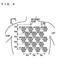
- Fig. 4 exemplarily shows an arrangement of a plurality of sensors (each corresponding to a SQUID magnetometer of a single channel) on a front side of the chest of a subject.
- Fig. 5 represents a group of time-series magnetic data representing a variation of a magnetic field for the period of a single heart beat that is obtained from the respective sensors of Fig. 4, as corresponding to their respective positions.
- Magnetic field distribution measurement device 1 shown in Fig. 2 outputs a group of time-series magnetic data corresponding to a plurality of positions (coordinates) for measurement, as shown in Fig. 5. If a group of time-series magnetic data is captured with a particular time noted, it is difficult to graphically (diagrammatically) represent ridges and troughs representing a distribution in intensity of a magnetic field present at a specific time on a front side of a chest to be measured, and magnetic field distribution data represented in a contour map such as an atmospheric pressure represented in a weather chart is accordingly obtained. In this sense also, data output from magnetic field distribution measurement device 1 can be captured as time-series data of a distribution of a magnetic field on a front side of a chest.
- a group of time-series, magnetic data such as output from magnetic field distribution measurement device 1, i.e., time-series magnetic field distribution data are fed to the first arithmetic device 2 of Fig. 2.
- the first arithmetic device 2 functions to obtain from magnetic field distribution data an electrical behavior in the chest, e.g., an intramyocardial excitation conduction rate.
- the first arithmetic device 2 From the time-series magnetic field distribution data generated by magnetic field distribution measurement device 1 the first arithmetic device 2 obtains three-dimensional information of an electrical behavior in a human body at a part to be measured (a heart in the present invention), e.g., an intramyocardial excitation conduction rate, as described hereinafter.
- an electrical behavior in a human body at a part to be measured e.g., an intramyocardial excitation conduction rate, as described hereinafter.
- the first arithmetic device 2 approximates time-series, magnetic field distribution data generated by magnetic field distribution measurement device 1.
- one or more small current element pieces i.e., current dipoles
- the small current element pieces are scattered in a measured magnetocardiographic distribution and a well known analysis methodology is employed to determine a parameter (positional information and electric-current vector) of each small current element piece with respect to a respective point for measurement.
- a well known analysis methodology using current dipoles is a well known technique, for example as specifically disclosed in Japanese Patent Laying-Open No. 5-157735, and it will not be described herein in detail.
- the first arithmetic device 2 initially generates data representing such a chronological variation of the position and electric current's direction of a small current element piece, as described above, and feeds the data to display device 4 at one input.
- the first arithmetic device 2 also uses the chronological variation to calculate an intramyocardial excitation conduction rate and the result may be generated in the form of numerical data and furthermore may be generated in the form of image data visibly representing the rate by an arrow having a length.
- the first arithmetic device 2 generates from the magnetic field distribution data generated by magnetic field distribution measurement device 1 a variety of forms of time-series data representing an intramyocardial excitation conduction rate to be analyzed, and input the generated time series data to display device 4 at one input.
- the second arithmetic device 3 shown in Fig. 2 receives image data of a plurality of sliced images (for example a dozen of such images obtained at a pitch of five millimeters) of the chest of the same subject that are previously taken using another tomographic analysis apparatus (not shown) such as MRI, x-ray CT, echocardiography or myocardial SPECT with an electrocardiography synchronization trigger applied.
- another tomographic analysis apparatus not shown
- the second arithmetic device 3 processes (interpolates) the data of the plurality of sliced images and subjects the data to three-dimensional, perspective conversion from a predetermined point of view to generate second data representing an anatomical image.
- forming a three-dimensional, anatomical image from a plurality of sliced images is a well-known technique, for example as specifically disclosed in Japanese Patent Laying-Open No. 11-128224 and International Publication WO 98/15226, and will not be described specifically.
- the second arithmetic device 3 generates the second data representing a three-dimensional, anatomical image of the chest of the same subject in a vicinity of his/her heart and feeds the second data to display device 4 at the other input.
- Display device 4 of Fig. 2 superimposes on a three-dimensional, anatomical image of a subject's chest based on the second data from the second arithmetic device 3 an image based on the first data from the first arithmetic device 2 and representing a chronological variation of a position and a direction of a current of a small current element piece in myocardium.
- Fig. 6 shows a manner of displaying a position and direction of a small current element piece representing an intramyocardial excitation current in a magnetocardiographic distribution at a specific time point, and an excitation conduction path before that time point is arrived at, as superimposed on a three-dimensional, anatomical image displayed by display device 4.
- Fig. 6 is a three-dimensional image obtained by interpolating approximately five tomographic images obtained by slicing a subject's chest at a pitch of five millimeters, for example.
- a depth of a displayed image is difficult to represent by drawing. It is, however, intended to show a stereoscopic, anatomical image providing a sense of a depth that is formed by combining a plurality of sliced images.
- an arrow A indicates the position and direction of a small current element piece representing an intramyocardial excitation current corresponding to the time point and its length represents the magnitude of the current.
- thick lines B, C, D represent a tracing of an intramyocardial excitation conduction path obtained by approximating a magnetic field of a heart by means of a small current element piece and more specifically, correspond to the small current element piece's positional variation chronologically linked together.
- a small current element piece has its position varying with time to form a dense tracing
- a small current element piece has its position varying with time to form a sparse tracing.
- the sparseness/denseness of the position of a small current element piece configuring each of thick lines B, C, D representing an excitation conduction path displayed on a screen allows their respective, intramyocardial excitation conduction rates to be visually recognized.
- the first arithmetic device 2 may calculate the exact, each intramyocardial excitation conduction rate and display device 4 may display it numerically.
- an intramyocardial excitation conduction rate can be displayed for each excitation conduction path to allow doctors to correctly understand a relative, positional relationship of a part in myocardium having a ventricular late potential, i.e., a part in myocardium providing un-uniform conduction of excitation on the anatomical image.
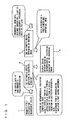
- Fig. 7 is a flow chart of a method effected by the magnetocardiographic diagnosis apparatus of the first embodiment to identify a part in myocardium providing un-uniform conduction of excitation.
- magnetic field distribution measurement device 1 is used to provide non-contact magnetic measurement on the chest of a human body at a plurality of coordinates, generate a plurality of time series data, and record the data if necessary.
- step S2 a plurality of MRI images taken with an electrocardiography synchronization trigger applied are interpolated by the second arithmetic device 3 (i.e., subjected to three-dimensional, perspective conversion from a predetermined point of view) to obtain a three-dimensional, anatomical image.
- an analysis start time point, an analysis end time point and an analysis time interval are set to be t s , t e and ⁇ t, respectively.
- step S4 analysis start time point t s is substituted into an analysis time point t to start an analysis. Then at step S5 until analysis time point t reaches analysis end time point t e the following process is effected.
- the first arithmetic device 2 approximates magnetocardiographic distribution data corresponding to a designated-analysis time point t, with one or a plurality of small current element pieces, to obtain data of the location, direction and magnitude of an excitation current in myocardium.
- step S7 the data of the location, direction and magnitude of the intramyocardial excitation current at time point t - ⁇ t, as obtained at step S6 of the previous loop preceding by time ⁇ t, is compared to the data corresponding to time point t, as obtained at step S6 of the current loop, and an intramyocardial excitation conduction rate is calculated.
- step S8 display device 4 displays data representing an intramyocardial excitation conduction rate, as superimposed on an anatomical image having undergone a three-dimensional, perspective conversion from a predetermined point of view.
- step S9 ⁇ t is added to analysis time point t.
- Steps S6-S9 are repeated until a decision is made at step S5 that analysis time point t has reached analysis end time point t e .
- display device 4 terminates displaying data representing the intramyocardial excitation conduction rate superimposed on the anatomical image.
- an image representing an intramyocardial excitation conduction rate obtained from a SQUID magnetometer obtaining a noninvasive magnetic measurement on a subject's chest can be superimposed on a three-dimensional, anatomical image and thus displayed to allow a doctor to three-dimensionally identify the anatomical, positional relationship, size and geometry of a part in myocardium having a ventricular late potential, i.e., a part in myocardium providing un-uniform conduction of excitation that might cause ventricular tachycardia.
- forming an anatomical image entails obtaining a large number of tomographic images of a subject and a test employing MRI, x-ray CT or the like is accordingly, previously conducted. This results in an increased number of tests and an increased burden on patients and also an obstacle to a treatment directly linked to a test.
- the present invention in a second embodiment can provide a magnetocardiographic diagnosis apparatus for ventricular late potential and a method of identifying a part in myocardium providing un-uniform conduction of excitation that are capable of eliminating the formation of an anatomical image to conduct a reduced number of tests and carry out a diagnosis and a test such that they are directly linked.
- Fig. 8 is a functional block diagram schematically showing a configuration of the magnetocardiographic diagnosis apparatus for ventricular late potential in the second embodiment.
- magnetic field distribution measurement device 1 With reference to Fig. 8, magnetic field distribution measurement device 1 will not be described as it has been described in the first embodiment.
- Magnetic field distribution measurement device 1 generates time-series, magnetic field distribution data and outputs the data to an arithmetic device 5 which in turn uses the received time-series, magnetic field distribution data and employs the aforementioned analysis technique using a current dipole to generate data regarding an intramyocardial, three-dimensional electrical behavior, e.g., an intramyocardial excitation current.
- Arithmetic device 5 uses the generated data of the excitation current to superimpose data representing a ventricular, intramyocardial excitation (stimulation) conduction path of a period corresponding to that from an electrocardiographically represented P wave to an electrocardiographically represented QRS complex and data representing an intramyocardial excitation conduction rate on each other and outputs the same to display device 6.
- Display device 6 superimposes an image representing the intramyocardial excitation conduction rate represented by the data generated by arithmetic device 5, on a three-dimensional image of the excitation conduction path also obtained by arithmetic device 5 and corresponding to the period from the P wave to the QRS complex, and displays the same. Consequently, such an anatomical image as used in the first embodiment can be dispensed with to three-dimensionally identify a positional relationship of a part in myocardium providing un-uniform conduction of excitation.
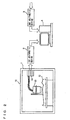
- Fig. 9 is a block diagram more specifically showing a configuration of the magnetocardiographic diagnosis apparatus of the second embodiment shown in Fig. 8.
- magnetic field distribution measurement device 1 With reference to Fig. 9, magnetic field distribution measurement device 1 will not be described as it is identical to that described with reference to Figs. 2 and 3.
- Magnetic field distribution measurement device 1 outputs time-series, magnetic field distribution data and outputs the data to arithmetic device 5 shown in Fig. 9.
- Arithmetic device 5 employs the analysis technique using a current dipole, as described above, to generate from time-series, magnetic field distribution data the data regarding an intramyocardial excitation current.
- Subject 12 has his/her electrocardiogram recorded by an electrocardiograph 21 to allow measured electrocardiographic waveform data of subject 12 to be fed to arithmetic device 5.
- the electrocardiogram and an event occurring in the heart can also be correlated.
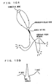
- FIG. 10A schematically representing a normal stimulation conduction path in a heart
- Fig. 10B representing an electrocardiographically represented waveform for a single heart beat.
- a sinoatrial node functions as a pacemaker determining a heart beat and it fires at predetermined intervals (a timing of a P wave of an electrocardiogram) to generate a pulse.
- This pulse is transmitted through a specific stimulation conduction path to an atrioventricular node and therein after a period of time elapses a pulse is transmitted through a bundle of His and a Purkinje fiber network to an underlying a ventricle and myocardial contraction erupts.
- This conduction of a stimulation from the bundle of His to the Purkinje fiber network corresponds to the period of the QRS complex in the electrocardiogram.
- arithmetic device 5 by analyzing magnetocardiography related to the period from the P wave to the QRS complex, i.e., by analyzing an intramyocardial excitation current, arithmetic device 5 generates image data representing a stimulation conduction path serving as a normal route, as shown in Fig. 10A.
- An image of a stimulation conduction path can be used in place of the anatomical image used in the first embodiment, as a template displayed. More specifically, a three-dimensional, anatomical image such as described in the first embodiment can be dispensed with if a stimulation conduction path of a normal route, as shown in Fig. 10A, is displayed, since a part in myocardium that exists in a neighboring ventricle and has a ventricular late potential, i.e., provides un-uniform conduction of excitation would be readily, anatomically correlated by a doctor and its location, size and geometry would be identified by the doctor.
- Arithmetic device 5 shown in Fig. 9 generates data representing a generated intramyocardial excitation conduction rate, superimposed on a displaying of a stimulation conduction circuit as a template, such as described above.
- a template such as described above.
- Display device 6 shown in Fig. 9 uses the data received from arithmetic device 5 to display an image representing an intramyocardial excitation conduction rate, as superimposed on a normal stimulation conduction circuit serving as a template.
- doctors can readily determine whether there is a condition allowing a reentry circuit to be readily formed in ventricular muscle.
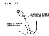
- Fig. 11 exemplarily shows a screen actually displayed by display device 6. It displays an image representing an intramyocardial excitation conduction rate for each excitation conduction path, superimposed on a normal stimulation conduction circuit serving as a template.
- Fig. 11 two arrows are shown, each indicating the position of an excitation conduction path approximated by a small current element piece (a current dipole). Each arrow has a length representing an excitation conduction rate.
- a doctor would be able to refer to a positional relationship of a respective excitation conduction path relative to the normal stimulation conduction path serving as a template, as shown in Fig. 11, to provide an anatomical correlation and would also be able to refer to a difference in excitation conduction rate between excitation conduction paths to identify the location, size and geometry of a part in a ventricle that has a ventricular late potential, i.e., a part in myocardium that provides un-uniform conduction of excitation.
- Figs. 12 and 13 are a flow chart representing a method effected by the magnetocardiographic diagnosis apparatus of the second embodiment to identify a part in myocardium providing un-uniform conduction of excitation.
- magnetic field distribution measurement device 1 is used to provide a non-contact magnetic measurement on the chest of a human body at a plurality of coordinates to generate and record a plurality of time-series magnetic data .
- an analysis start time point is set to correspond to an electrocardiographically represented P-wave start time point t sP , an analysis end time point to an electrocardiographically represented QRS-complex end time point t eQRS , and an analysis time interval to ⁇ t.
- step S13 time point t sP is substituted into analysis time point t.
- step S14 until an analysis time reaches time point t eQRS the following steps S15-S17 are repeated.
- arithmetic device 5 approximates magnetocardiographic distribution data of a designated analysis time point t with one or more small current element pieces to obtain data regarding the location, direction and magnitude of an intramyocardial excitation current.
- step S16 the data of the intramyocardial excitation current obtained at step S16 undergoes three-dimensional, perspective conversion from a predetermined point of view and displayed in an image.
- step S17 ⁇ t is added to analysis time point t and the process returns to step S14 and a decision is made as to whether time point t eQRS has been reached. If so then it means that there has been obtained image data representing a stimulation conduction path corresponding to a normal route, as shown in Fig. 10A, as corresponding in an electrocardiographically represented waveform to the period from the P wave to the QRS complex.
- step S18 shown in Fig. 13, and an analysis start time point, an analysis end time point and an analysis time interval are set to be t s , t e and ⁇ t, respectively.
- step S19 analysis start time point t s is substituted into analysis time point t.
- step S20 the following steps S21-S24 are effected in a loop.
- arithmetic device 5 approximate magnetocardiographic distribution data of designated analysis time t with one or more small current element pieces to obtain data regarding the location, direction and magnitude of an intramyocardial excitation current.
- step S22 the data of the location, direction and magnitude of the intramyocardial excitation current at time point t - ⁇ t, as obtained at step S21 of the previous loop preceding by time ⁇ t, is compared to the data corresponding to time point t, as obtained at step S21 of the current loop, and an intramyocardial excitation conduction rate is calculated.
- step S23 display device 4 displays data representing an intramyocardial excitation conduction rate, as superimposed on an image of a normal stimulation conduction path having undergone a three-dimensional, perspective conversion from a predetermined point of view.
- step S24 ⁇ t is added to analysis time point t and the process returns to step S20 and a decision is made as to whether analysis end time t e has been reached.
- data representing an intramyocardial excitation conduction rate is superimposed on and displayed together with an image of a stimulation conduction path (Fig. 10A) obtained through the Fig. 12 flow chart.
- an image representing an intramyocardial excitation conduction rate obtained from a SQUID magnetometer obtaining a noninvasive magnetic measurement on a subject's chest can be superimposed on a normal stimulation conduction path serving as a template and it can thus be displayed to eliminate the necessity of superimposing it on an anatomical image to allow a doctor to three-dimensionally identify the positional relationship, size and geometry of apart in myocardium having a ventricular late potential, i.e., a part in myocardium providing un-uniform conduction of excitation that might cause ventricular tachycardia, as seen relative to a stimulation conduction path.
- the second embodiment can eliminate the necessity of previously conducting a test to obtain the anatomical image.
- a current dipole is used to approximate an excitation conduction path.
- Such an image of a normal stimulation conduction path can be obtained by operating operation unit 5 to obtain an intramyocardial current density distribution from time-series, magnetic field distribution data generated by magnetic field distribution measurement device 1, and the intramyocardial current distribution density can be obtained from the time-series, magnetic field distribution data by employing synthetic aperture magnetometric (SMA), multiple signal classification (MUSIC) or other similar, various techniques.
- SMA synthetic aperture magnetometric
- MUSIC multiple signal classification
- SAM and MUSIC have been studied and developed for example in the fields of radar and sonar and are well known techniques. However, they have hitherto been unapplied to magnetocardiographic diagnosis.
- SAM and MUSIC are well known techniques and the algorithms using these techniques to obtain a current density distribution are significantly complicated, and they will not be described specifically.
- SAM is specifically described by Robinson SE and Vrba J, “Functional Neuroimaging by Synthetic Aperture Magnetometry (SAM)” in Proceedings of the 11th International Conference on Biomagnetism, “Reent Advances in Biomagnetism, “published by Tohoku University Press, 1999, pp. 302-305.
- MUSIC is specifically described by Hiroshi Hara and Shinya Kurishiro, "Science of Cerebric Magnetism-SQUID Measurement and Medical Applications, "published by Ohmsha, January 25, 1997, pp. 117-119.
- an intramyocardial excitation conduction rate obtained through a non-invasive magnetic measurement on a patient's chest can be displayed visibly on a three-dimensional, anatomical image to allow three-dimensional identification of the location, size and geometry of a part having a ventricular late potential, i.e., a part in myocardium providing un-uniform conduction of excitation.
- This allows a non-invasive diagnosis of a part in myocardium providing un-uniform conduction of excitation or having a ventricular late potential that might cause ventricular tachycardia.
- a rapid and safe test can be conducted.
- high frequency catheter ablation is used to provide a treatment, it can previously, significantly narrow down a region to be electrophysiologically tested and thus effectively, significantly reduce doses of x ray radiation that are received by doctors and radiographers.
- a subject's intramyocardial excitation conduction rate can be superimposed on the same subject's normal stimulation conduction path from a sinoatrial node to a bundle of His-Purkinje fiber network to eliminate the necessity of obtaining an anatomical image-to three-dimensionally identify the position of a part in myocardium providing un-uniform conduction of excitation, i.e., the localization and spread of a ventricular late potential. Furthermore, a test conducted to obtain the anatomical image can be eliminated and more economically efficient diagnosis can thus be provided.
- a magnetocardiographic diagnosis apparatus for a ventricular late potential and a method of identifying a part in myocardium providing un-uniform conduction of excitation can three-dimensionally identify the position, size and geometry of the part in myocardium providing un-uniform conduction of excitation. It is useful in non-invasively diagnosing a part in myocardium providing un-uniform conduction of excitation or having a ventricular late potential that might cause ventricular tachycardia.
Landscapes
- Health & Medical Sciences (AREA)
- Life Sciences & Earth Sciences (AREA)
- Engineering & Computer Science (AREA)
- Medical Informatics (AREA)
- Physics & Mathematics (AREA)
- Heart & Thoracic Surgery (AREA)
- Pathology (AREA)
- Biomedical Technology (AREA)
- Biophysics (AREA)
- Molecular Biology (AREA)
- Surgery (AREA)
- Animal Behavior & Ethology (AREA)
- General Health & Medical Sciences (AREA)
- Public Health (AREA)
- Veterinary Medicine (AREA)
- Nuclear Medicine, Radiotherapy & Molecular Imaging (AREA)
- Radiology & Medical Imaging (AREA)
- High Energy & Nuclear Physics (AREA)
- Cardiology (AREA)
- Optics & Photonics (AREA)
- Computer Vision & Pattern Recognition (AREA)
- Theoretical Computer Science (AREA)
- General Physics & Mathematics (AREA)
- Software Systems (AREA)
- General Engineering & Computer Science (AREA)
- Computer Hardware Design (AREA)
- Computer Graphics (AREA)
- Dentistry (AREA)
- Oral & Maxillofacial Surgery (AREA)
- Pulmonology (AREA)
- Measurement And Recording Of Electrical Phenomena And Electrical Characteristics Of The Living Body (AREA)
- Measuring Magnetic Variables (AREA)
- Magnetic Resonance Imaging Apparatus (AREA)
Abstract
Description
Claims (16)
- A magnetocardiographic diagnosis apparatus for ventricular late potential, comprising:a magnetic field distribution measurement device (1) performing a non-contact magnetic measurement on a subject's chest at a plurality of coordinates to obtain a plurality of time-series magnetic data corresponding to said plurality of coordinates, and also using said plurality of time-series magnetic data to generate time-series magnetic field distribution data on said chest;a first arithmetic device (2) using said generated time-series magnetic field distribution data to generate data representative of a three-dimensional, intramyocardial, electrical behavior of said subject;a second arithmetic device (3) processing separately provided, tomographic, thoracic data of said subject to generate data representative of an anatomical image; anda display device (4) displaying an image of said three-dimensional, intramyocardial, electrical behavior represented by said data generated by said first arithmetic device, as superimposed on said anatomical image represented by said data generated by said second arithmetic device, thereby capable of three-dimensionally identifying localization of a ventricular late potential attributed to intramyocardial, un-uniform conduction of excitation.
- The apparatus of claim 1, wherein said data generated by said first arithmetic device and representative of said three-dimensional, intramyocardial, electrical behavior is data representative of an intramyocardial excitation conduction rate.
- The apparatus of claim 2, wherein said first arithmetic device approximates by means of one or more small current element pieces a part in myocardium corresponding to an excitation conduction path and calculates a temporal variation of a position of said small current element piece to generate data representative of an intramyocardial excitation conduction rate.
- The apparatus of claim 3, wherein said first arithmetic device operates based on said calculated temporal variation of the position of said small current element piece to generate data representative of a difference in intramyocardial excitation conduction rate for each excitation conduction path.
- A magnetocardiographic diagnosis apparatus for ventricular late potential, comprising:a magnetic field distribution measurement device (1) performing a non-contact magnetic measurement on a subject's chest at a plurality of coordinates to obtain a plurality of time-series magnetic data corresponding to said plurality of coordinates, and also using said plurality of time-series magnetic data to generate time-series magnetic field distribution data on said chest;an arithmetic device (5) using said generated time-series magnetic field distribution data to generate data representative of a three-dimensional, intramyocardial, electrical behavior of said subject; anda display device (6) using the data generated by said arithmetic device to superimpose together an image representing a stimulation conduction path of said subject extending from a sinoatrial node to a bundle of His-Purkinje fiber network and an image representing a three-dimensional, intramyocardial, electrical behavior and display said images, thereby capable of three-dimensionally identifying localization of a ventricular late potential attributed to intramyocardial, un-uniform conduction of excitation.
- The apparatus of claim 5, wherein the data generated by said arithmetic device and representative of said three-dimensional, intramyocardial, electrical behavior is data representative of an intramyocardial excitation conduction rate.
- The apparatus of claim 6, wherein said arithmetic device approximates by means of one or more small current element pieces a part in myocardium corresponding to an excitation conduction path and calculates a temporal variation of a position of said small current element piece to generate data representative of said intramyocardial excitation conduction rate.
- The apparatus of claim 7, wherein said arithmetic device operates based on said calculated temporal variation of the position of said small current element piece to generate data representative of a difference in intramyocardial excitation conduction rate for each excitation conduction path.
- A method of identifying a part in myocardium providing un-uniform conduction of excitation, comprising the steps of:performing a non-contact magnetic measurement on a subject's chest at a plurality of coordinates to obtain a plurality of time-series magnetic data corresponding to said plurality of coordinates and used to generate time-series magnetic field distribution data of said chest and generating first data representative of a three-dimensional, intramyocardial, electrical behavior of said subject from the generated time-series magnetic field distribution data;processing separately fed, tomographic, thoracic image data of said subject to generate second data representative of an anatomical image; anddisplaying an image of said three-dimensional, intramyocardial, electrical behavior represented by said first data, as superimposed on said anatomical image represented by said second data, to allow three-dimensional identification of localization of a ventricular late potential attributed to intramyocardial, un-uniform conduction of excitation.
- The method of claim 9, wherein said three-dimensional, intramyocardial, electrical behavior represented by said first data is an intramyocardial excitation conduction rate.
- The method of claim 10, wherein the step of generating said first data uses one or more small current element pieces to approximate a part in myocardium corresponding to an excitation conduction path and calculates a temporal variation of a position of said small current element piece to generate data representative of said intramyocardial excitation conduction rate.
- The method of claim 11, wherein the step of generating said first data uses said calculated temporal variation of the position of said small current element piece to generate data representative of a difference in excitation conduction rate for each excitation conduction path.
- A method of identifying a part in myocardium providing un-uniform conduction of excitation, comprising the steps of:performing a non-contact magnetic measurement on a subject's chest at a plurality of coordinates to obtain a plurality of time-series magnetic data corresponding to said plurality of coordinates and used to generate time-series magnetic field distribution data of said chest and generating data representative of a three-dimensional, intramyocardial, electrical behavior of said subject from the generated time-series magnetic field distribution data; andusing said generated data to superimpose together an image representing a stimulation conduction path of said subject extending from a sinoatrial node to a bundle of His-Purkinje fiber network and an image representing a three-dimensional, intramyocardial, electrical behavior, and thus displaying said images to allow three-dimensional identification of localization of a ventricular late potential attributed to intramyocardial, un-uniform conduction of excitation.
- The method of claim 13, wherein said three-dimensional, intramyocardial, electrical behavior represented by said data is an intramyocardial excitation conduction rate.
- The method of claim 14, wherein the step of generating said data uses one or more small current element pieces to approximate a part in myocardium corresponding to an excitation conduction path and calculates a temporal variation of a position of said small current element piece to generate data representative of said intramyocardial excitation conduction rate.
- The method of claim 15, wherein the step of generating said data uses said calculated temporal variation of the position of said small current element piece to generate data representative of a difference in said intramyocardial excitation conduction rate of each excitation conduction path.
Applications Claiming Priority (3)
| Application Number | Priority Date | Filing Date | Title |
|---|---|---|---|
| JP2000217835A JP3712350B2 (en) | 2000-07-18 | 2000-07-18 | Cardiac magnetic field diagnostic apparatus for ventricular delayed potential and method for operating the same |
| JP2000217835 | 2000-07-18 | ||
| PCT/JP2001/006194 WO2002005715A1 (en) | 2000-07-18 | 2001-07-17 | Cardiac magnetic field diagnosing apparatus by late ventricular potential and method of locating intramyocardial excitement uneven propagation portion |
Publications (2)
| Publication Number | Publication Date |
|---|---|
| EP1302161A1 true EP1302161A1 (en) | 2003-04-16 |
| EP1302161A4 EP1302161A4 (en) | 2008-02-13 |
Family
ID=18712890
Family Applications (1)
| Application Number | Title | Priority Date | Filing Date |
|---|---|---|---|
| EP01950019A Withdrawn EP1302161A4 (en) | 2000-07-18 | 2001-07-17 | MAGNETIC FIELD DIAGNOSTIC DIAGNOSIS DEVICE BY LATE-VENTRICULAR POTENTIAL AND METHOD OF LOCATING AN INEQUAL INTRAMYOCARDIAL EXCITATION PROPAGATION PART |
Country Status (5)
| Country | Link |
|---|---|
| US (1) | US6941165B2 (en) |
| EP (1) | EP1302161A4 (en) |
| JP (1) | JP3712350B2 (en) |
| AU (1) | AU2001271070A1 (en) |
| WO (1) | WO2002005715A1 (en) |
Cited By (1)
| Publication number | Priority date | Publication date | Assignee | Title |
|---|---|---|---|---|
| WO2018168864A1 (en) * | 2017-03-17 | 2018-09-20 | Ricoh Company, Ltd. | Information processing apparatus, information processing method, program, and biological signal measurement system |
Families Citing this family (7)
| Publication number | Priority date | Publication date | Assignee | Title |
|---|---|---|---|---|
| JP3712349B2 (en) * | 2000-07-18 | 2005-11-02 | 独立行政法人科学技術振興機構 | Surviving myocardial diagnostic apparatus and operating method thereof |
| JP3712348B2 (en) * | 2000-07-18 | 2005-11-02 | 独立行政法人科学技術振興機構 | Cardiac magnetic field diagnostic apparatus for atrial flutter and atrial fibrillation and method for operating the same |
| JP4027867B2 (en) * | 2003-09-10 | 2007-12-26 | 株式会社日立ハイテクノロジーズ | Biomagnetic field measurement device |
| US9585600B2 (en) | 2012-10-02 | 2017-03-07 | Covidien Lp | Magnetic field viewing film for tracking in-situ surgical applications |
| JP6399852B2 (en) * | 2014-08-07 | 2018-10-03 | フクダ電子株式会社 | Pulse wave measuring device and biological information measuring device |
| US12383184B2 (en) | 2021-03-12 | 2025-08-12 | Cardioinsight Technologies Inc. | Late activation of cardiac signals |
| CN113317793B (en) * | 2021-06-11 | 2023-02-17 | 宁波大学 | Magnetocardiogram high-frequency signal analysis method, storage medium, and electronic device |
Family Cites Families (18)
| Publication number | Priority date | Publication date | Assignee | Title |
|---|---|---|---|---|
| EP0443069A1 (en) * | 1990-02-22 | 1991-08-28 | Siemens Aktiengesellschaft | Method of measuring the electric or magnetic field pattern with a sensor arrangement |
| US5341811A (en) * | 1991-03-26 | 1994-08-30 | Allegheny-Singer Research Institute | Method and apparatus for observation of ventricular late potentials |
| JP2949983B2 (en) | 1991-12-10 | 1999-09-20 | ダイキン工業株式会社 | Physical source analysis method and apparatus |
| JPH05220124A (en) * | 1992-02-13 | 1993-08-31 | Fujitsu Ltd | Biomagnetic measurement device |
| US5228443A (en) * | 1992-03-27 | 1993-07-20 | General Electric Company | Method for estimation and display of current source distribution from electric and magnetic measurements and 3D anatomical data |
| GB9310604D0 (en) * | 1993-05-21 | 1993-07-07 | British Tech Group | Analysis of heart waveforms |
| WO1995003843A1 (en) * | 1993-07-30 | 1995-02-09 | The Regents Of The University Of California | Endocardial infusion catheter |
| JPH08289877A (en) | 1995-04-24 | 1996-11-05 | Toshiba Corp | Method for simulating tissue excitement propagation process and apparatus for diagnosing electromagnetic phenomenon in tissue using this method |
| EP0968683B1 (en) | 1996-10-08 | 2011-05-25 | Hitachi Medical Corporation | Method and apparatus for forming and displaying image from a plurality of sectional images |
| DE19808985B4 (en) * | 1997-03-07 | 2012-06-14 | Hitachi, Ltd. | Method and device for biomagnetic field measurement |
| JPH10276998A (en) | 1997-04-10 | 1998-10-20 | Toshiba Corp | Simulation device for excitement propagation process |
| US5827195A (en) * | 1997-05-09 | 1998-10-27 | Cambridge Heart, Inc. | Electrocardiogram noise reduction using multi-dimensional filtering |
| JP3660781B2 (en) * | 1997-05-26 | 2005-06-15 | 株式会社東芝 | Diagnostic device for intracardiac electrical phenomena |
| US6473518B1 (en) * | 1997-10-02 | 2002-10-29 | Hitachi, Ltd. | Method of measuring a biomagnetic field, method of analyzing a measured biomagnetic field, method of displaying biomagnetic field data, and apparatus therefor |
| JPH11128224A (en) | 1997-10-28 | 1999-05-18 | Mitsubishi Heavy Ind Ltd | Ultrasonic 3-dimensional image reorganizing device |
| JP4208275B2 (en) * | 1997-10-30 | 2009-01-14 | 株式会社東芝 | Diagnostic device for intracardiac electrical phenomenon and method for displaying the phenomenon |
| IT1302900B1 (en) * | 1998-12-04 | 2000-10-10 | Riccardo Fenici | AMAGNETIC CATHETER FOR THE SINGLE-CATHETER REGISTRATION OF MULTIPLE SINGLE-PHASE ACTION POTENTIALS, LOCABLE THREE-DIMENSIONALLY AND |
| JP2001112732A (en) * | 1999-10-15 | 2001-04-24 | Hitachi Ltd | Inspection equipment using nuclear magnetic resonance |
-
2000
- 2000-07-18 JP JP2000217835A patent/JP3712350B2/en not_active Expired - Fee Related
-
2001
- 2001-07-17 WO PCT/JP2001/006194 patent/WO2002005715A1/en not_active Ceased
- 2001-07-17 EP EP01950019A patent/EP1302161A4/en not_active Withdrawn
- 2001-07-17 US US10/333,056 patent/US6941165B2/en not_active Expired - Fee Related
- 2001-07-17 AU AU2001271070A patent/AU2001271070A1/en not_active Abandoned
Cited By (1)
| Publication number | Priority date | Publication date | Assignee | Title |
|---|---|---|---|---|
| WO2018168864A1 (en) * | 2017-03-17 | 2018-09-20 | Ricoh Company, Ltd. | Information processing apparatus, information processing method, program, and biological signal measurement system |
Also Published As
| Publication number | Publication date |
|---|---|
| JP2002028145A (en) | 2002-01-29 |
| AU2001271070A1 (en) | 2002-01-30 |
| WO2002005715A1 (en) | 2002-01-24 |
| EP1302161A4 (en) | 2008-02-13 |
| US20040049119A1 (en) | 2004-03-11 |
| JP3712350B2 (en) | 2005-11-02 |
| US6941165B2 (en) | 2005-09-06 |
Similar Documents
| Publication | Publication Date | Title |
|---|---|---|
| US11182911B2 (en) | Ultrasound-based geometry determination for electrophysiological mapping | |
| US7123952B2 (en) | Cardiac magnetic field diagnozer for atrial flutter and atrial fibrillation and method for identifying electric turning path of atrial flutter and atrial fibrillation | |
| Tavarozzi et al. | Current perspective magnetocardiography: Current status and perspectives, part ii: Clinical applications | |
| US7144376B2 (en) | Liable cardiac muscle diagnosing apparatus and liable cardiac muscle analyzing method by magnetic field measurements | |
| EP3795075B1 (en) | Using supplemental information to improve inverse problem solutions | |
| EP1769741B1 (en) | Cardiac magnetic field diagnostic apparatus and damaged cardiac muscle three-dimensional localization evaluating method | |
| US10959638B2 (en) | Conduction velocity and pattern mapping | |
| US20140235996A1 (en) | Method for non-invasive mapping of myocardial electric activity | |
| Leder et al. | Noninvasive biomagnetic imaging in coronary artery disease based on individual current density maps of the heart | |
| US6941165B2 (en) | Cardiac magnetic field diagnosing apparatus by late ventricular potential and method of locating intramyocardial excitement uneven propagation portion | |
| JP3835805B2 (en) | Cardiac magnetic field diagnostic apparatus and operating method thereof | |
| JP2002355229A (en) | Magnetic field analysis method and current distribution visualization device | |
| Muller et al. | Localization of a ventricular tachycardia-focus with multichannel magnetocardiography and three-dimensional current density reconstruction | |
| JP3809454B2 (en) | Cardiac magnetic field diagnostic apparatus and operating method thereof | |
| Agren et al. | Magnetocardiographic localization of arrhythmia substrates: a methodology study with accessory pathway ablation as reference | |
| Stroink | Forty years of magnetocardiology | |
| Mäkijärvi et al. | New trends in clinical magnetocardiography | |
| Tao | Advanced Source Reconstruction and Volume Conductor Modeling for Fetal Magnetocardiography | |
| Baron-Palucka | Magnetocardiography-measurement conduction, data formats and diagnostic applications. | |
| Rodriguez-Rivera | Biomagnetic and Bioelectric Imaging | |
| Seger et al. | Online noninvasive localization of accessory pathways in the EP lab | |
| Wilson | Tracking Fetal Movement Through Source Localization From Multisensor Magnetocardiographic Recordings | |
| Vashi | MAGNETOCARDIOGRAPHY-An Effective Tool for Heart Scan |
Legal Events
| Date | Code | Title | Description |
|---|---|---|---|
| PUAI | Public reference made under article 153(3) epc to a published international application that has entered the european phase |
Free format text: ORIGINAL CODE: 0009012 |
|
| 17P | Request for examination filed |
Effective date: 20030130 |
|
| AK | Designated contracting states |
Designated state(s): AT BE CH CY DE DK ES FI FR GB GR IE IT LI LU MC NL PT SE TR |
|
| RIN1 | Information on inventor provided before grant (corrected) |
Inventor name: NAKAI, KENJI Inventor name: YAMAZAKI, KEITA,C/O TECHNICAL LAB. TAKENAKA CORP. Inventor name: KAWAZOE, KOHEI Inventor name: FUJITA, SATOSHI,C/O OSAKA GAS CO., LTD. Inventor name: TAMURA, ITSURO,C/O OSAKA GAS CO., LTD. Inventor name: YOSHIZAWA, MASAHITO |
|
| RBV | Designated contracting states (corrected) |
Designated state(s): DE FI FR GB |
|
| A4 | Supplementary search report drawn up and despatched |
Effective date: 20080114 |
|
| RIC1 | Information provided on ipc code assigned before grant |
Ipc: A61B 5/05 20060101ALI20080108BHEP Ipc: G06T 17/40 20060101ALI20080108BHEP Ipc: G06F 19/00 20060101ALI20080108BHEP Ipc: A61B 5/04 20060101AFI20080108BHEP |
|
| 17Q | First examination report despatched |
Effective date: 20080514 |
|
| STAA | Information on the status of an ep patent application or granted ep patent |
Free format text: STATUS: THE APPLICATION IS DEEMED TO BE WITHDRAWN |
|
| 18D | Application deemed to be withdrawn |
Effective date: 20080925 |