EP1301440B1 - Reacteur biologique a lit fixe immerge et procede de traitement d'effluents liquides - Google Patents
Reacteur biologique a lit fixe immerge et procede de traitement d'effluents liquides Download PDFInfo
- Publication number
- EP1301440B1 EP1301440B1 EP20010955401 EP01955401A EP1301440B1 EP 1301440 B1 EP1301440 B1 EP 1301440B1 EP 20010955401 EP20010955401 EP 20010955401 EP 01955401 A EP01955401 A EP 01955401A EP 1301440 B1 EP1301440 B1 EP 1301440B1
- Authority
- EP
- European Patent Office
- Prior art keywords
- tank
- effluents
- supports
- fact
- tanks
- Prior art date
- Legal status (The legal status is an assumption and is not a legal conclusion. Google has not performed a legal analysis and makes no representation as to the accuracy of the status listed.)
- Expired - Lifetime
Links
Images


Classifications
-
- C—CHEMISTRY; METALLURGY
- C02—TREATMENT OF WATER, WASTE WATER, SEWAGE, OR SLUDGE
- C02F—TREATMENT OF WATER, WASTE WATER, SEWAGE, OR SLUDGE
- C02F3/00—Biological treatment of water, waste water, or sewage
- C02F3/02—Aerobic processes
- C02F3/10—Packings; Fillings; Grids
-
- C—CHEMISTRY; METALLURGY
- C02—TREATMENT OF WATER, WASTE WATER, SEWAGE, OR SLUDGE
- C02F—TREATMENT OF WATER, WASTE WATER, SEWAGE, OR SLUDGE
- C02F3/00—Biological treatment of water, waste water, or sewage
- C02F3/02—Aerobic processes
- C02F3/06—Aerobic processes using submerged filters
-
- C—CHEMISTRY; METALLURGY
- C02—TREATMENT OF WATER, WASTE WATER, SEWAGE, OR SLUDGE
- C02F—TREATMENT OF WATER, WASTE WATER, SEWAGE, OR SLUDGE
- C02F2209/00—Controlling or monitoring parameters in water treatment
- C02F2209/06—Controlling or monitoring parameters in water treatment pH
-
- C—CHEMISTRY; METALLURGY
- C02—TREATMENT OF WATER, WASTE WATER, SEWAGE, OR SLUDGE
- C02F—TREATMENT OF WATER, WASTE WATER, SEWAGE, OR SLUDGE
- C02F2209/00—Controlling or monitoring parameters in water treatment
- C02F2209/22—O2
-
- Y—GENERAL TAGGING OF NEW TECHNOLOGICAL DEVELOPMENTS; GENERAL TAGGING OF CROSS-SECTIONAL TECHNOLOGIES SPANNING OVER SEVERAL SECTIONS OF THE IPC; TECHNICAL SUBJECTS COVERED BY FORMER USPC CROSS-REFERENCE ART COLLECTIONS [XRACs] AND DIGESTS
- Y02—TECHNOLOGIES OR APPLICATIONS FOR MITIGATION OR ADAPTATION AGAINST CLIMATE CHANGE
- Y02W—CLIMATE CHANGE MITIGATION TECHNOLOGIES RELATED TO WASTEWATER TREATMENT OR WASTE MANAGEMENT
- Y02W10/00—Technologies for wastewater treatment
- Y02W10/10—Biological treatment of water, waste water, or sewage
Definitions
- the present invention relates to a biological reactor immersed fixed bed for the removal of pollutants essentially soluble liquid effluents under the action of bacteria contained by the reactor and likely to digest organic compounds effluents to be treated. It also relates to a method of treatment of liquid effluents implementing such a reactor.
- Patent Application EP853067 describes a bed reactor immersed fixture of the latest generation that presents a specific structure allowing optimal ventilation.
- the support of bacteria consists in a rotating disk that presents at any time of the rotation a submerged part and an emerging part in contact with the surrounding air allowing aeration optimal.
- the reactors of the third generation have a progress compared to the first and second reactors generations but are still not satisfied on the performance and load plan.
- the known reactors of the third generation require installation at the reactor outlet of a clarifier before the discharge of the treated water into the nature.
- they are not suitable for treating discharges whose biodegradability ratio COD / DEO-, BOD. being the biological oxygen demand in 5 days, this ratio to be at least 0.5.
- the aim of the invention is, above all, to remedy these disadvantages and, in particular, to provide a reactor compact that can fit in a small space while presenting optimized processing performance.
- the reactor according to the invention is suitable for the treatment of effluents with a very poor biodegradability, ie less than 0.5.
- the reactor according to the invention comprises two tanks so as to further improve the overall efficiency of the elimination of Constant surface charge COD or increase the load permissible surface area at constant yield.
- the flow of effluents from the first tank to the second is carried out by means known to the man of the occupation, and advantageously by underflow or overflow.
- the effluents if they are brought into the first tank at the top, they are routed in the second tank by underflow, and conversely, if they are brought into the first tank at the level of its part lower, they are conveyed in the second tank by overflow.
- the reactor therefore comprises three tanks placed in series and all having bacteria supports having a specific surface greater than or equal to 100 m 2 / m 3 , preferably greater than 125 m 2 / m 3 , a vacuum percentage greater than 90%, preferably greater than 95% and aeration means placed at the bottom of each tank.
- specific surface refers to the relationship between the sum of the surfaces of each carrier of bacteria and the apparent volume of the medium, that is the volume of the reactor occupied by the structure consisting of supports units of bacteria fixed together.
- void percentage means the difference between the apparent volume of the medium and its actual volume reduced as a percentage of the apparent volume.
- the means of aeration can be constituted as indicated below.
- These recirculation means can be constituted as shown below.
- the effluents to be treated are kept in circulation in the first tank then they are transferred by underflow or over-poured into the second tank, after neutralization of their acidity then they are transferred by underflow or overflow to a third tank in which purification is finalized and in which a clarification is done.
- the aeration means are selected so that that the concentration of oxygen in the reaction medium, that is to say in the charged waters circulating in the spaces formed between the supports of bacteria, either greater than about 6ppm, preferably 7.5ppm.
- Such aeration means are constituted by a blower which sends oxygen into fine bubbles arranged parallel to one another and fixed on the entire surface of the bottom of the tank.
- the support of the bacteria is chosen from conventional bacteria carriers which simultaneously have a specific surface greater than or equal to 100 m 2 / m 3 , preferably greater than 125 m 2 / m 3 and a void percentage greater than 90%, preferably greater than 95%.
- such supports are bulk and plastic supports. According to a mode of particularly advantageous embodiment, such supports are polypropylene scrapers or bottle brushes.
- the means for adjusting the pH may consist of by a pH control line placed, preferably, between two tanks, advantageously between the first and the second tank.
- a pH control line includes a sensor connected to a pH meter, a transmitter of the signal emitted by the sensor and a regulator to which is transmitted the signal and that can be constituted by a valve introduction of neutralizing agent.
- the pH is brought back at a value generally less than 7,5 and, preferably between 6.5 and 7.
- Means for recirculating effluents inside a tank are constituted for example by a pump that sucks a certain volume of effluents into the lower part of the tank then reintroduced in the part opposite top of the tank.
- the biological reactor is designated as a whole by 1 and includes three compartments 2, 3 and 4 placed in series, each of these compartments materializing a tank.
- each of the tanks are constituted by the walls of the reactor and by two partitions respectively 7 in 8 respectively separating the compartments 2 and 3 and 3 and 4.
- the effluents to be treated are conveyed into the compartment 2 by a pipe 5 which opens at the bottom of the compartment 2; these effluents are circulated inside this compartment 2 as indicated above by a pump along a path approximately materialized by the arrows F 1 and F 2 .
- the upper level of the effluent in the compartment 2 is shown in 2a.
- Effluents move from compartment 2 to compartment 3 by overflow, circulate in the compartment 3 in which their upper level is materialized in 3a following a path approximately represented by the arrow F3 and then go into the compartment 4 by underflow thanks to a passage 9 arranged between the partition 8 and the bottom of the reactor.
- the effluent path in the compartment 4 is indicated by the arrow F 4 and their level in this compartment is shown in 4a.
- Atmospheric air insufflation installation globally designated by 10 and powered by a fan 11.
- each of compartments 2, 3 and 4 is arranged a globally designated 12 basket with brackets of bacteria.
- These bacteria carriers are polypropylene brushes or trays with an axis central 14 disposed vertically in the basket and on which are arranged perpendicular to the axis 14 of the strands 15 of circular cross section.
- the supports are placed in each of the baskets so that the central axes 14 are vertical and parallel to each other.
- the number of brushes per basket and the distance between the brushes are determined so that a surface area of 125 m 2 / m 3 and a void percentage of 95% are obtained simultaneously.
- a device 16 for measuring the pH is disposed at proximity to the area in which the crossing takes place overflow from compartment 2 to compartment 3.
- device is connected to a reservoir 17 of neutralizing agent such as soda, itself equipped with a pump 18 for conveying said agent within the compartment 2.
- a device 19 makes it possible to circulate in a loop the effluents within the first tank 2.
- This device 19 has a pipe 20 whose open end is placed inside the tank 2 near the partition 7 and in the lower part of the tank, a pump 21 connecting the pipe 20 and a pipe 22, to extract the effluents, to route them to through line 22 to the upper entrance 23 of the tank 2 where they are again admitted to the reactor, flow control means 24 disposed on the pipe 22 and a regulating valve 25 making it possible to adjust the flow rate admitted to the tank 2.
- a reservoir 26 containing the necessary nutrients bacteria is provided with a pump 27 and is connected to the channeling 22. Thus, nutrients are brought into the circuit allowing the loop circulation of effluents in the tank 2.
- the effluents to be treated are brought into the first tank 2 which fills, then the tanks 3 and 4 fill up in their turn. When the effluent level has reached the upper limit 2a, 3a and 4a in each compartment, the reactor is then in its operating state. The effluents are introduced at constant flow into the reactor and treated effluents 6 come out at constant flux of the tank 4.
- the bacteria attached to the supports digest the organic compounds of the effluents thus reducing the COD. Aerobic bacterial activity is made possible by the presence of oxygen in the reaction medium. oxygen is delivered by the oxygen supplies placed at the bottom of the tank and arranged in such a way that the concentration in oxygen in the loaded water is about 8ppm.
- the effluents to be treated are conveyed into the reactor at the level of the tank 2 in the space delimited by the side edge of the tank and the basket 12 disposed in the tank 2 near the bottom of the tank. These effluents are forced to circulate in a loop inside the tank 2 to means of a system 19 comprising a suction of effluent placed at the bottom of the tank 2 in the vicinity of the partition 7 separating the tank 2 from the tank 3.
- the effluents thus aspirated are reintroduced at the inlet 23 of the reactor, that is to say in the upper part of the tank 2. This aspiration and: this forced reintroduction of effluents impose a loop circulation of effluents to the inside of the tank 2 according to the arrows F1 and F2.
- the effluents are conveyed into the second tank 3 by overflow. However, beforehand, a pH measurement effluent at the outlet of the tank 2 was carried out and a adjustment done automatically by adding soda in the tank 2 at the top to have a pH included between 6.5 and 7.
- the effluents are conveyed from the second tank 3 to the third tank 4 by underflow, through the passage 9 arranged between the partition 8 and the bottom of the reactor.
- the forced flow of effluents in the reactor allows to obtain an optimal residence time of the effluents.
- the passage in the third tank 4 allows no only to finalize the purification but also to clarify the solution.
- the effluents 6 leaving the reactor are not turbid and can be rejected directly in the wild or be rejected after underwent an additional step of settling or filtration if the required concentration of suspended solids is less than 50ppm.
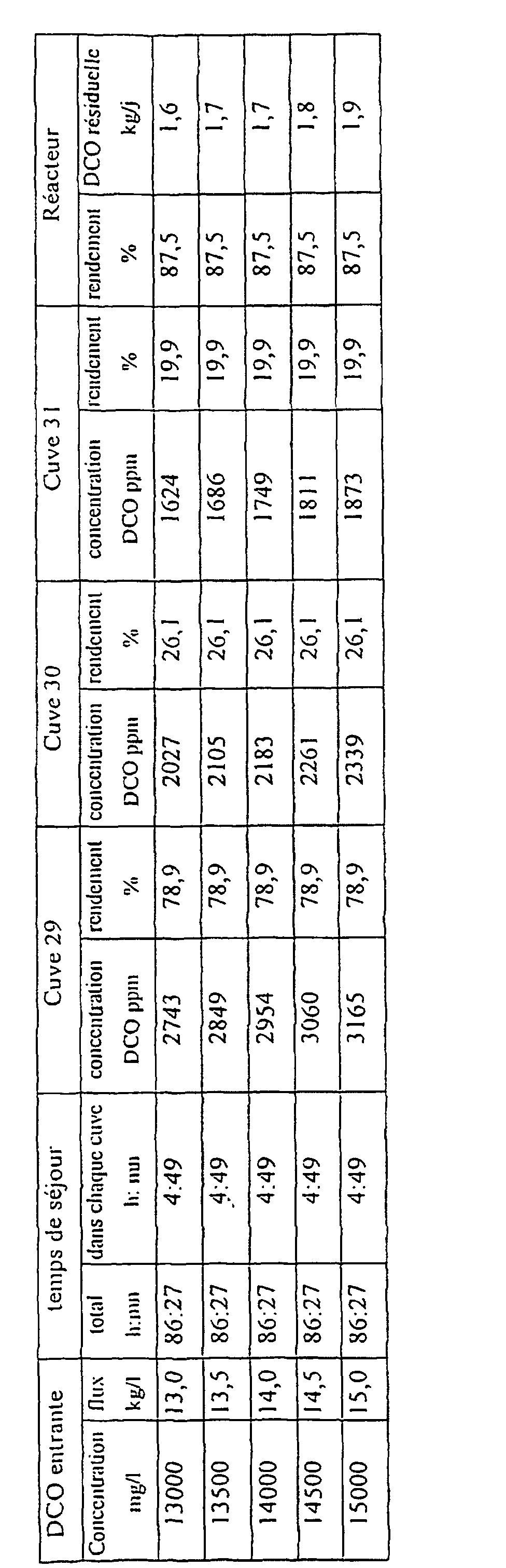
- FIG. 2 a second mode of realization of a biological reactor according to the invention, which is designated as a whole by 28 and which includes three separate cylindrical tanks one of the other 29, 30 and 31 and a clarifier 32 placed in series.
- each tank 29, 30, 31 is arranged a notebook globally designated by 33 including 34 bacteria that are bottle brushes described above in connection with Figure 1.
- These brushes are arranged so that their central axis 35 is parallel to the central axis of the cylindrical vessels and so that a specific surface of 125 m 2 / m 3 and a percentage of vacuum of 95% are obtained simultaneously. .
- an insufflation installation of atmospheric air to breathe oxygen in the form of fine bubbles is powered by a system compressed air supply 37.
- the effluents to be treated are conveyed into the tank 29 by a pipe 38 which opens at the level of the part the upper part of the tank 29, the effluents are put into circulation inside the tank 29 by a system of line 39 and pump 39a which allows to extract the effluent in the lower part of the tank 29 and the reintroduce at the level of the upper part of the tank 29.
- the upper level of the effluents in the tank 29 is shown in 29a.
- the effluents are conveyed from the tank 29 into the tank 30 through a pipe 40 provided with valves 40a and 40b.
- Line 40 connects the lower part of the tank 29 at the top of the tank 30.
- the effluents are therefore conveyed into the tank 30 at its upper part where they circulate to the lower part of the tank 30 and are conveyed to the tank 31 by the pipe 41 connecting the lower part of the tank 30 to the part The upper level of the tank. in tanks 30 and 31 is shown respectively in 30a and 31a.
- the effluents circulate from the part superior to the lower part where they are evacuated through line 42 to clarifier 32.
- Clarifier 32 the higher level of effluent is materialized in 32a.
- reactor of FIG. 2 comprises regulating means pH and means of feeding nutrients to the bacteria.
- the means of regulating the pH consist of a neutralizing agent reservoir 45 and a device for measuring the pH 46 disposed on the pipe 40 connecting the tank 29 to the tank 30.
- the introduction of neutralization is done at the level of the tank 29 using the recirculation circuit (39, 39a).
- the recirculation circuit (39, 39a) has a 39b average allowing the control of the hydraulic load in the tank 29.
- the effluents to be treated are brought into the first tank 29 which fills, then the tanks 30 and 31 are fill in turn, as well as clarifier 32.
- the reactor is then in its state of operation. Effluents are introduced to flow constant in the reactor and treated effluents come out constant flow of the clarifier 32.
- the bacteria attached to the supports digest the organic compounds of the effluents thus reducing the COD. Aerobic bacterial activity is made possible by the presence of oxygen in the reaction medium. oxygen is delivered by the atmospheric air inlets 36 placed at the bottom of each tank and arranged in such a way that the oxygen concentration in the loaded water either about 8ppm.
- the effluents to be treated are conveyed into the reactor at the level of the tank 29. These effluents are forced to circulate in a loop inside the tank 29 by means of of a 39-39a system including effluent suction placed at the bottom of the tank 2. The effluents thus sucked are reintroduced into the upper part of the tank 29. This forced aspiration and reintroduction of effluents impose a loop circulation of effluents inside the tank 29.
- a measurement of the pH of the effluents leaving the tank 29 is performed and an adjustment is done automatically by addition of soda in the tank 29 in order to have an included pH between 6.5 and 7.
- the effluents are conveyed from the second tank 30 to the third tank 31.
- the effluents freed from most of the Soluble pollutants are drawn at the level of the bottom of the reactor vessel 31 and conveyed by the line 42 to the clarifier 32.
- the purified water is evacuated from exit 43 at the upper level of the clarifier and sludge are removed from the the bottom of the clarifier to the device 44 where they are recovered and possibly incinerated
- the invention also relates to a method for treating liquid effluents charged with pollutants.
- the method is a biological process according to which the effluents to be treated are placed in a submerged fixed-bed biological reactor comprising means for aeration of the effluents and are brought into contact with bacteria capable of digesting pollutants, characterized in that the bacteria which can proliferate on supports present in the reactor which are such that they simultaneously have a specific surface greater than or equal to 100 m 2 / m 3 , preferably greater than or equal to 125 m 2 / m 3 and a void percentage greater than 90 %, preferably greater than 95%.
- the effluents charged to be treated are supplemented with oxygen at a concentration greater than 6 ppm, preferably greater than 7.5 ppm.
- the pH of the reaction medium is set during the reaction.
- the bacteria support used is identical in each of the tanks 29, 30 and 31, and has a specific surface area of 125 m 2 / m 3 and a void percentage of 95%.
- the volume load of the tank 29 is 16.2 kgDCO / m 3 . j, that of the tank 30 of 3.4 kgDCO / m 3 . and that of the tank 31 of 2.5 kgDCO / m 3 .
- the surface charge of the tank 29 is 127.3 gDCO / m 2 .j, that of the tank 30 of 26.9 gDCO / m 2 .j and that of the tank 31 of 19.8 gDCO / m 2. .
- the overall volume load is 4.6 kg COD / m 3 .J and the overall surface charge is 36 gDCO / m 2 .day.
Landscapes
- Life Sciences & Earth Sciences (AREA)
- Biodiversity & Conservation Biology (AREA)
- Microbiology (AREA)
- Hydrology & Water Resources (AREA)
- Engineering & Computer Science (AREA)
- Environmental & Geological Engineering (AREA)
- Water Supply & Treatment (AREA)
- Chemical & Material Sciences (AREA)
- Organic Chemistry (AREA)
- Biological Treatment Of Waste Water (AREA)
Description
- des réacteurs dans lesquels les bactéries sont en suspension,
- des réacteurs à lit fixé à ruissellement dans lesquels les bactéries sont fixées sur des supports sur lesquels on fait ruisseler les effluents liquides à traiter,
- des réacteurs à lit fixé immergé, dans lesquels les bactéries sont fixées sur des supports eux mêmes immergés dans les effluents à traiter.
- qu'il comporte des moyens propres à permettre l'obtention d'une circulation en boucle des effluents à l'intérieur d'au moins l'une des cuves,
- que les moyens d'aération dont il est équipé, sont sélectionnés de façon telle qu'ils soient capables de créer dans le milieu réactionnel, c'est à dire dans les eaux chargées en bactéries et en effluents à traiter, une concentration en oxygène supérieure à 6ppm, de préférence supérieure à 7,5ppm,
- qu'il comporte des moyens de neutralisation de l'acidité du milieu réactionnel, autrement dit de réglage de la valeur du pH en cours de réaction.
Claims (8)
- Réacteur biologique à lit fixé immergé comprenant au moins une cuve destinée à être remplie d'effluents à traiter dans lesquels sont complètement immergés des supports de bactéries, ce réacteur qui est équipé de moyens d'aération disposés dans la partie inférieure de la cuve étant caractérisé par le fait que les supports de bactéries ont une surface spécifique supérieure ou égale à 100 m2/m3, de préférence supérieure à 125 m2/m3 et un pourcentage de vide supérieur à 90%, de préférence supérieur à 95%, ce réacteur présentant de plus au moins l'une des caractéristiques supplémentaires suivantes résidant dans le fait que :des moyens propres à permettre l'obtention d'une circulation en boucle des effluents à l'intérieur d'au moins l'une des cuves sont prévus,les moyens d'aération permettant de maintenir dans le milieu, c'est à dire dans les eaux chargées, une concentration en oxygène supérieure à 6ppm, de préférence supérieure à 7,5ppm,des moyens de neutralisation de l'acidité du milieu réactionnel, autrement dit de réglage de la valeur du pH en cours de réaction sont prévus.
- Réacteur biologique à lit fixé immergé selon la revendication 1, caractérisé par le fait qu'il comporte de deux à six cuves, de préférence quatre cuves et plus préférentiellement encore trois cuves, placées en série et des moyens propres à permettre le passage des effluents d'une cuve vers la cuve suivante.
- Réacteur biologique à lit fixé immergé selon la revendication 1 ou la revendication 2, caractérisé par le fait que les supports de bactéries sont des supports plastiques en vrac.
- Réacteur biologique à lit fixé immergé selon la revendication 3, caractérisé par le fait que les supports sont des écuvillons
- Réacteur biologique à lit fixé immergé selon l'une quelconque des revendications 2 à 4, caractérisé par le fait qu'il comporte trois cuves placées en série, chacune des cuves étant dotée de supports de bactéries constitués de goupillons et comportant des moyens d'aération disposés dans la partie inférieure de la cuve, qui permettent de maintenir une concentration en oxygène de l'ordre de 8ppm dans le milieu,
la première cuve étant dotée de moyens propres à permettre l'obtention d'une circulation en boucle des effluents à traiter,
des moyens de neutralisation de l'acidité des effluents étant prévus entre la première et la seconde cuve,
les effluents étant amenés à passer de la première cuve à la seconde cuve par sur-verse ou sous-verse,
les effluents étant amenés à passer de la seconde cuve vers la troisième cuve par sous-verse ou sur-verse. - Procédé biologique de traitement d'effluents liquides chargés en polluants, selon lequel les effluents à traiter sont placés dans un réacteur biologique à lit fixe complètement immergé comprenant des moyens d'aération des effluents et sont mis en contact avec des bactéries capables de digérer les polluants caractérisé par le fait que les bactéries peuvent proliférer sur des supports présents dans le réacteur, lesdits supports présentant simultanément une surface spécifique supérieure ou égale à 100m2/m3, de préférence supérieure ou égale à 125m2/m3 et un pourcentage de vide supérieur à 90%, de préférence supérieur à 95%.
- Procédé selon la revendication 6, caractérisé par le fait que les effluents chargés à traiter sont additionnés d'oxygène à une concentration supérieure à 6 ppm, de préférence supérieure à 7,5 ppm.
- Procédé selon la revendication 6 ou la revendication 7, caractérisée par le fait que le pH du milieu réactionnel est réglé en cours de réaction.
Applications Claiming Priority (3)
| Application Number | Priority Date | Filing Date | Title |
|---|---|---|---|
| FR0009328A FR2811658B1 (fr) | 2000-07-17 | 2000-07-17 | Reacteur biologique a lit fixe immerge et procede de traitement d'effluents liquides |
| FR0009328 | 2000-07-17 | ||
| PCT/FR2001/002241 WO2002006165A1 (fr) | 2000-07-17 | 2001-07-11 | Reacteur biologique a lit fixe immerge et procede de traitement d'effluents liquides |
Publications (2)
| Publication Number | Publication Date |
|---|---|
| EP1301440A1 EP1301440A1 (fr) | 2003-04-16 |
| EP1301440B1 true EP1301440B1 (fr) | 2005-03-16 |
Family
ID=8852573
Family Applications (1)
| Application Number | Title | Priority Date | Filing Date |
|---|---|---|---|
| EP20010955401 Expired - Lifetime EP1301440B1 (fr) | 2000-07-17 | 2001-07-11 | Reacteur biologique a lit fixe immerge et procede de traitement d'effluents liquides |
Country Status (6)
| Country | Link |
|---|---|
| EP (1) | EP1301440B1 (fr) |
| AU (1) | AU2001277573A1 (fr) |
| DE (1) | DE60109452T2 (fr) |
| ES (1) | ES2239153T3 (fr) |
| FR (1) | FR2811658B1 (fr) |
| WO (1) | WO2002006165A1 (fr) |
Cited By (2)
| Publication number | Priority date | Publication date | Assignee | Title |
|---|---|---|---|---|
| US8067436B2 (en) | 2003-09-26 | 2011-11-29 | Exelixis, Inc. | c-Met modulators and methods of use |
| US8877776B2 (en) | 2009-01-16 | 2014-11-04 | Exelixis, Inc. | (L)-malate salt of N-(4-{[6,7-bis(methyloxy) quinolin-4-yl]oxy}phenyl)-N'-(4-fluorophenyl)cyclopropane-1,1-dicarboxamide |
Families Citing this family (2)
| Publication number | Priority date | Publication date | Assignee | Title |
|---|---|---|---|---|
| CN1323038C (zh) * | 2005-12-09 | 2007-06-27 | 宁波德安城市生态技术集团有限公司 | 一种用以污水处理的生物反应器 |
| UA108618C2 (uk) | 2009-08-07 | 2015-05-25 | Застосування c-met-модуляторів в комбінації з темозоломідом та/або променевою терапією для лікування раку |
Family Cites Families (3)
| Publication number | Priority date | Publication date | Assignee | Title |
|---|---|---|---|---|
| DE2002926A1 (de) * | 1970-01-23 | 1971-07-29 | Roesler Norbert Dipl Ing | Verfahren zur Reinigung von gering,maessig und stark verschmutzten Abwaessern |
| DE3503723A1 (de) * | 1985-02-04 | 1986-08-14 | Leningradskij inženerno-stroitel'nyj institut, Leningrad | Vorrichtung zur wasseraufbereitung fuer fischzuchtbecken |
| KR930001217B1 (ko) * | 1990-08-30 | 1993-02-22 | 현대엔지니어링 주식회사 | 고농도 유기폐수의 처리방법 및 그 장치 |
-
2000
- 2000-07-17 FR FR0009328A patent/FR2811658B1/fr not_active Expired - Fee Related
-
2001
- 2001-07-11 WO PCT/FR2001/002241 patent/WO2002006165A1/fr not_active Ceased
- 2001-07-11 AU AU2001277573A patent/AU2001277573A1/en not_active Abandoned
- 2001-07-11 DE DE2001609452 patent/DE60109452T2/de not_active Expired - Fee Related
- 2001-07-11 ES ES01955401T patent/ES2239153T3/es not_active Expired - Lifetime
- 2001-07-11 EP EP20010955401 patent/EP1301440B1/fr not_active Expired - Lifetime
Cited By (6)
| Publication number | Priority date | Publication date | Assignee | Title |
|---|---|---|---|---|
| US8067436B2 (en) | 2003-09-26 | 2011-11-29 | Exelixis, Inc. | c-Met modulators and methods of use |
| US8178532B2 (en) | 2003-09-26 | 2012-05-15 | Exelixis, Inc. | c-Met modulators and method of use |
| US8476298B2 (en) | 2003-09-26 | 2013-07-02 | Exelixis, Inc. | c-Met modulators and method of use |
| US8497284B2 (en) | 2003-09-26 | 2013-07-30 | Exelixis, Inc. | C-met modulators and method of use |
| US9174947B2 (en) | 2003-09-26 | 2015-11-03 | Exelixus, Inc. | c-Met modulators and methods of use |
| US8877776B2 (en) | 2009-01-16 | 2014-11-04 | Exelixis, Inc. | (L)-malate salt of N-(4-{[6,7-bis(methyloxy) quinolin-4-yl]oxy}phenyl)-N'-(4-fluorophenyl)cyclopropane-1,1-dicarboxamide |
Also Published As
| Publication number | Publication date |
|---|---|
| WO2002006165A1 (fr) | 2002-01-24 |
| AU2001277573A1 (en) | 2002-01-30 |
| DE60109452T2 (de) | 2006-04-13 |
| FR2811658A1 (fr) | 2002-01-18 |
| DE60109452D1 (de) | 2005-04-21 |
| FR2811658B1 (fr) | 2004-07-02 |
| ES2239153T3 (es) | 2005-09-16 |
| EP1301440A1 (fr) | 2003-04-16 |
Similar Documents
| Publication | Publication Date | Title |
|---|---|---|
| KR100441208B1 (ko) | 생물 여과 기술을 이용하는 회분식 폐수처리장치 및 이를이용한 폐수처리방법 | |
| FR2548656A1 (fr) | Procede d'epuration a activation biologique d'eaux usees contenant des matieres azotees et dispositif pour la mise en oeuvre du procede | |
| JP3323040B2 (ja) | 超純水製造装置 | |
| US6758965B2 (en) | Apparatus for treating wastewater from catering industry | |
| EP1301440A1 (fr) | Reacteur biologique a lit fixe immerge et procede de traitement d'effluents liquides | |
| EP3681844B1 (fr) | Reacteur et procede de traitement biologique des eaux residuaires | |
| FR2668765A1 (fr) | Methode de traitement des eaux residuaires par le procede a boue activee. | |
| KR100491900B1 (ko) | 생물학적 폐ㆍ하수 처리장치 및 그것을 이용한 생물학적 폐ㆍ하수 처리방법 | |
| FR2690683A1 (fr) | Procédé et installation d'épuration d'eaux résiduaires, et en particulier d'élimination de la pollution azotée, par voie biologique. | |
| CA1039418A (fr) | Traitement biologique contre-courant des liquides | |
| EP0492690B1 (fr) | Procédé et réacteur de traitement d'eau utilisant un lit granulaire adapté pour assurer une filtration ou une filtration associée à une épuration biologique de l'eau | |
| JP3095620B2 (ja) | 生物学的窒素除去装置 | |
| CN119019060A (zh) | 一种污水处理系统及污水处理方法 | |
| WO2005014493A1 (fr) | Reacteur de denitrification a culture fixee | |
| JP2006289153A (ja) | 汚水浄化方法及び装置 | |
| JPH10296283A (ja) | 担体併用生物反応槽の担体分離方法 | |
| JP2009082847A (ja) | 好気濾床槽及びこの好気濾床槽の運転方法 | |
| JP2003010871A (ja) | 汚水処理装置及びその運転方法 | |
| JP2556413B2 (ja) | 有機性排水の処理方法 | |
| KR102517076B1 (ko) | 저비중 슬러지의 분리배출장치, 이를 포함하는 시스템 및 그 동작방법 | |
| EP0611728B1 (fr) | Installation et procédé pour l'épuration biologique des eaux d'écoulement | |
| JP3970612B2 (ja) | 浄化処理装置および浄化処理方法 | |
| JP4710146B2 (ja) | 加圧流動床方式排水処理装置 | |
| RU2255051C1 (ru) | Установка для биологической очистки сточных вод от органических соединений и соединений азота | |
| EP2571820A1 (fr) | Bioreacteur a oxygenation et lits bacteriens separes et procede de traitement |
Legal Events
| Date | Code | Title | Description |
|---|---|---|---|
| PUAI | Public reference made under article 153(3) epc to a published international application that has entered the european phase |
Free format text: ORIGINAL CODE: 0009012 |
|
| 17P | Request for examination filed |
Effective date: 20021230 |
|
| AK | Designated contracting states |
Designated state(s): AT BE CH CY DE DK ES FI FR GB GR IE IT LI LU MC NL PT SE TR |
|
| AX | Request for extension of the european patent |
Extension state: AL LT LV MK RO SI |
|
| 17Q | First examination report despatched |
Effective date: 20031009 |
|
| RBV | Designated contracting states (corrected) |
Designated state(s): BE DE ES FR GB IT |
|
| GRAP | Despatch of communication of intention to grant a patent |
Free format text: ORIGINAL CODE: EPIDOSNIGR1 |
|
| GRAS | Grant fee paid |
Free format text: ORIGINAL CODE: EPIDOSNIGR3 |
|
| GRAA | (expected) grant |
Free format text: ORIGINAL CODE: 0009210 |
|
| AK | Designated contracting states |
Kind code of ref document: B1 Designated state(s): BE DE ES FR GB IT |
|
| REG | Reference to a national code |
Ref country code: GB Ref legal event code: FG4D Free format text: NOT ENGLISH |
|
| REG | Reference to a national code |
Ref country code: IE Ref legal event code: FG4D Free format text: FRENCH |
|
| REF | Corresponds to: |
Ref document number: 60109452 Country of ref document: DE Date of ref document: 20050421 Kind code of ref document: P |
|
| GBT | Gb: translation of ep patent filed (gb section 77(6)(a)/1977) |
Effective date: 20050516 |
|
| REG | Reference to a national code |
Ref country code: ES Ref legal event code: FG2A Ref document number: 2239153 Country of ref document: ES Kind code of ref document: T3 |
|
| REG | Reference to a national code |
Ref country code: FR Ref legal event code: CD Ref country code: FR Ref legal event code: CJ |
|
| PLBE | No opposition filed within time limit |
Free format text: ORIGINAL CODE: 0009261 |
|
| STAA | Information on the status of an ep patent application or granted ep patent |
Free format text: STATUS: NO OPPOSITION FILED WITHIN TIME LIMIT |
|
| 26N | No opposition filed |
Effective date: 20051219 |
|
| PGFP | Annual fee paid to national office [announced via postgrant information from national office to epo] |
Ref country code: FR Payment date: 20060531 Year of fee payment: 6 |
|
| PGFP | Annual fee paid to national office [announced via postgrant information from national office to epo] |
Ref country code: GB Payment date: 20060620 Year of fee payment: 6 |
|
| PGFP | Annual fee paid to national office [announced via postgrant information from national office to epo] |
Ref country code: DE Payment date: 20060629 Year of fee payment: 6 |
|
| PGFP | Annual fee paid to national office [announced via postgrant information from national office to epo] |
Ref country code: ES Payment date: 20060717 Year of fee payment: 6 |
|
| PGFP | Annual fee paid to national office [announced via postgrant information from national office to epo] |
Ref country code: BE Payment date: 20060726 Year of fee payment: 6 |
|
| PGFP | Annual fee paid to national office [announced via postgrant information from national office to epo] |
Ref country code: IT Payment date: 20060731 Year of fee payment: 6 |
|
| BERE | Be: lapsed |
Owner name: *CFPI NUFARM Effective date: 20070731 |
|
| GBPC | Gb: european patent ceased through non-payment of renewal fee |
Effective date: 20070711 |
|
| PG25 | Lapsed in a contracting state [announced via postgrant information from national office to epo] |
Ref country code: DE Free format text: LAPSE BECAUSE OF NON-PAYMENT OF DUE FEES Effective date: 20080201 |
|
| PG25 | Lapsed in a contracting state [announced via postgrant information from national office to epo] |
Ref country code: GB Free format text: LAPSE BECAUSE OF NON-PAYMENT OF DUE FEES Effective date: 20070711 |
|
| REG | Reference to a national code |
Ref country code: FR Ref legal event code: ST Effective date: 20080331 |
|
| PG25 | Lapsed in a contracting state [announced via postgrant information from national office to epo] |
Ref country code: BE Free format text: LAPSE BECAUSE OF NON-PAYMENT OF DUE FEES Effective date: 20070731 |
|
| PG25 | Lapsed in a contracting state [announced via postgrant information from national office to epo] |
Ref country code: FR Free format text: LAPSE BECAUSE OF NON-PAYMENT OF DUE FEES Effective date: 20070731 |
|
| REG | Reference to a national code |
Ref country code: ES Ref legal event code: FD2A Effective date: 20070712 |
|
| PG25 | Lapsed in a contracting state [announced via postgrant information from national office to epo] |
Ref country code: ES Free format text: LAPSE BECAUSE OF NON-PAYMENT OF DUE FEES Effective date: 20070712 |
|
| PG25 | Lapsed in a contracting state [announced via postgrant information from national office to epo] |
Ref country code: IT Free format text: LAPSE BECAUSE OF NON-PAYMENT OF DUE FEES Effective date: 20070711 |