EP1300975A1 - Optical demultiplexing system for wavelength bands - Google Patents
Optical demultiplexing system for wavelength bands Download PDFInfo
- Publication number
- EP1300975A1 EP1300975A1 EP02292364A EP02292364A EP1300975A1 EP 1300975 A1 EP1300975 A1 EP 1300975A1 EP 02292364 A EP02292364 A EP 02292364A EP 02292364 A EP02292364 A EP 02292364A EP 1300975 A1 EP1300975 A1 EP 1300975A1
- Authority
- EP
- European Patent Office
- Prior art keywords
- channels
- bands
- stage
- inter
- band
- Prior art date
- Legal status (The legal status is an assumption and is not a legal conclusion. Google has not performed a legal analysis and makes no representation as to the accuracy of the status listed.)
- Withdrawn
Links
- 230000003287 optical effect Effects 0.000 title claims abstract description 20
- 238000001914 filtration Methods 0.000 claims abstract description 9
- 230000003595 spectral effect Effects 0.000 claims description 17
- 230000000737 periodic effect Effects 0.000 claims description 12
- 210000001520 comb Anatomy 0.000 claims description 4
- 238000000926 separation method Methods 0.000 abstract description 4
- 239000000835 fiber Substances 0.000 description 13
- 230000005540 biological transmission Effects 0.000 description 9
- 238000000605 extraction Methods 0.000 description 5
- 239000013307 optical fiber Substances 0.000 description 5
- 238000000034 method Methods 0.000 description 4
- 230000008901 benefit Effects 0.000 description 3
- 238000004891 communication Methods 0.000 description 3
- 238000001228 spectrum Methods 0.000 description 3
- RYGMFSIKBFXOCR-UHFFFAOYSA-N Copper Chemical compound [Cu] RYGMFSIKBFXOCR-UHFFFAOYSA-N 0.000 description 1
- 240000008042 Zea mays Species 0.000 description 1
- 239000003086 colorant Substances 0.000 description 1
- 229910052802 copper Inorganic materials 0.000 description 1
- 239000010949 copper Substances 0.000 description 1
- 230000008030 elimination Effects 0.000 description 1
- 238000003379 elimination reaction Methods 0.000 description 1
- 238000005516 engineering process Methods 0.000 description 1
- 238000003780 insertion Methods 0.000 description 1
- 230000037431 insertion Effects 0.000 description 1
- 239000012212 insulator Substances 0.000 description 1
- 238000004519 manufacturing process Methods 0.000 description 1
- 230000000116 mitigating effect Effects 0.000 description 1
Images

Classifications
-
- H—ELECTRICITY
- H04—ELECTRIC COMMUNICATION TECHNIQUE
- H04J—MULTIPLEX COMMUNICATION
- H04J14/00—Optical multiplex systems
- H04J14/02—Wavelength-division multiplex systems
-
- G—PHYSICS
- G02—OPTICS
- G02B—OPTICAL ELEMENTS, SYSTEMS OR APPARATUS
- G02B6/00—Light guides; Structural details of arrangements comprising light guides and other optical elements, e.g. couplings
- G02B6/24—Coupling light guides
- G02B6/26—Optical coupling means
- G02B6/28—Optical coupling means having data bus means, i.e. plural waveguides interconnected and providing an inherently bidirectional system by mixing and splitting signals
- G02B6/293—Optical coupling means having data bus means, i.e. plural waveguides interconnected and providing an inherently bidirectional system by mixing and splitting signals with wavelength selective means
- G02B6/29346—Optical coupling means having data bus means, i.e. plural waveguides interconnected and providing an inherently bidirectional system by mixing and splitting signals with wavelength selective means operating by wave or beam interference
- G02B6/29358—Multiple beam interferometer external to a light guide, e.g. Fabry-Pérot, etalon, VIPA plate, OTDL plate, continuous interferometer, parallel plate resonator
-
- G—PHYSICS
- G02—OPTICS
- G02B—OPTICAL ELEMENTS, SYSTEMS OR APPARATUS
- G02B6/00—Light guides; Structural details of arrangements comprising light guides and other optical elements, e.g. couplings
- G02B6/24—Coupling light guides
- G02B6/26—Optical coupling means
- G02B6/28—Optical coupling means having data bus means, i.e. plural waveguides interconnected and providing an inherently bidirectional system by mixing and splitting signals
- G02B6/293—Optical coupling means having data bus means, i.e. plural waveguides interconnected and providing an inherently bidirectional system by mixing and splitting signals with wavelength selective means
- G02B6/29379—Optical coupling means having data bus means, i.e. plural waveguides interconnected and providing an inherently bidirectional system by mixing and splitting signals with wavelength selective means characterised by the function or use of the complete device
- G02B6/2938—Optical coupling means having data bus means, i.e. plural waveguides interconnected and providing an inherently bidirectional system by mixing and splitting signals with wavelength selective means characterised by the function or use of the complete device for multiplexing or demultiplexing, i.e. combining or separating wavelengths, e.g. 1xN, NxM
- G02B6/29386—Interleaving or deinterleaving, i.e. separating or mixing subsets of optical signals, e.g. combining even and odd channels into a single optical signal
Definitions
- the present invention relates to fiber transmission technology optical, by spectral division multiplexing, and more particularly relates to a system for improving the separation of wavelength bands in a transmission mode where a large number of channels with the same destination are transported respectively by a series of distinct wavelengths, regularly distributed in the spectrum, all these wavelengths being transported on the same fiber and constituting what is called a strip.
- a strip in the shape of a comb of finite width, and with teeth regularly spaced.
- Several bands can be interleaved if the spectral space between two successive channels of a band is at least equal to the space required for a channel.
- a first step in the use of optical fibers consisted essentially of point-to-point links, between two nodes of a network.
- the transport is carried out on a single wavelength, most often around 1550 nanometers (nm), wavelength best suited for transport over long distances.
- optical signals can be modulated to very high frequencies, which must be expressed in giga or 10 9 bits per second, the amount of information to be transported quickly exceeded the capacity offered. If the fiber itself is inexpensive, deploying it can be labor intensive and extremely costly. Rather than deploying more optical fibers, when the capacity of an installed network becomes insufficient, the solution has been found in making better use of the fibers already in place.
- WDM Widelength Division Multiplexing'
- DWDM Dense WDM
- Routing by group of wavelengths or bands conducted in most cases to a reduction in the overall cost of the optical network to the extent where it allows to share the cost of the filtering and switching devices present in the nodes, between the different wavelengths constituting the band.
- the contiguous or adjacent wavelength bands have a major advantage over interlaced wavelength bands, in that they use simplified filtering devices, less expensive and also more tolerant from the point of view of the physical constraints they impose (in contrast, the bands interlaced, require filtering devices individually affecting each wave length).
- Fibers are used to interconnect the optical equipment of communication located at the nodes of a network.
- An essential device for a knot network is then an optical insertion and extraction multiplexer, or OADM for 'Optical Add / Drop Multiplexer'.
- OADM optical insertion and extraction multiplexer
- Its purpose is, as the name suggests, to be able to divert or demultiplex and insert or multiplex, in optical mode, local traffic (for example, at an entry and exit point on a secondary network) while the rest of the traffic must continue on its way towards other nodes of the network. it assumes that at least one wavelength carrying local information (one channel) must be derived and inserted. In practice, for the reasons mentioned above, these are rather bands of wavelengths (a series of channels) which must be thus derived and inserted to exchange a sufficient amount of information with local applications.
- the bands 110 and 120 are separated by a band 139 corresponding to two channels, but which is not used to transmit signals.
- the bands 120 and 130 are separated by a band 140 corresponding to two channels, but which is not used to transmit signals. Indeed, if we use equipment ordinary strip demultiplexing, strip extraction 110, 120, 130 does cannot be performed without having to sacrifice so-called inter-band channels which are between bands 110 and 120, and between bands 120 and 130. This is due to the large proximity to contiguous wavelengths that can be transported with mode says DWDM (involving spectral separations between channels of 100 GHz, 50 GHz even 25 GHz), and the inherent limitations of the power of spectral discrimination (also called selectivity) of ordinary tape demultiplexing equipment, such as than the demultiplexer 100.
- the bandwidth of the ordinary demultiplexer100 is illustrated by a trapezoid 150 having sides whose slope is not sufficiently steep. This bandwidth is wide enough to cover the channels with a length band of waves (four channels in this example) but has insufficient selectivity for effectively eliminate the inter-band channels constituting bands 139 and 140. These therefore, inter-band channels cannot be used, which reduces significant transport capacity on optical fiber.
- the object of the invention is to provide a system of optical demultiplexing allowing the effective use of these wavelengths inter-bands that would otherwise be lost.
- the system according to the invention makes it possible to use all the channels and in particular the channels conventionally called inter-band that were not used to transmit signals. These channels become usable in particular for network management and wavelength bands, because the system according to the invention makes it possible to obtain sufficient selectivity, while comprising only simple means and few expensive in each of the two floors.
- the first stage consists of a periodic strip deinterlacer, 210, which is intended to separate the two combs 320 and 321.
- a first exit from the demultiplexer 210 provides the comb 320 (bands 320a and 320b) which includes all inter-band channels. These channels are extracted but remain multiplexed in a same multiplex, in this first example.
- the two bands 320a and 320b can be used to transport signals, but not separately.
- a second exit of the deinterlacer 210 provides the comb 321 which includes all the channels used to transport information.
- the strip deinterlacer 210 preferably consists a periodic filter (or a cascade of periodic filters) with selectivity sufficient to effectively attenuate bands 320a and 320b of inter-band channels in the multiplex (including bands 321a, 321b, 321c) supplied on the second exit.
- the second stage consists of a periodic strip demultiplexer, 240. It has three outputs providing bands 213a, 321 b, 321 c separately.
- the demultiplexer constituting the second stage 240 can be without disadvantage a ordinary demultiplexer of contiguous wavelength bands with low selectivity spectral since the inter-band channels (bands 320a and 320b) have been previously extracted with great selectivity by the first stage 210.
- the production of the deinterlacer on stage 210 calls on techniques known to those skilled in the art. It is however detailed on an enlarged part of FIG. 2. It comprises a circulator 252 having an input connected to the fiber 205, and a first output connected to a periodic optical filter 254, for example a so-called filter Fabry-Perot.
- the spectral separation power of the filter 254 must be sufficient to allow the extraction of bands 320a, 320b of inter-band channels. These bands appear on output 256 of the periodic filter 254.
- a second output 258 of circulator 252 constitutes the second output of the deinterlacer 210, providing the bands 321a, 321b, 321c.
- the circulator 252 being a component expensive, it can advantageously be replaced by an insulator followed by a simple coupler.
- FIG. 3 essentially repeats the content of FIG. 2. It represents a demultiplexing system for the case where the two bands of inter-band channels, 320a and 320b, are used separately.
- this second embodiment includes a periodic strip demultiplexer, 360, having an input connected to the first output of the deinterlacer 210, and having two outputs for separately extracting the bands 320a and 320b which are also used to transport signals.
- each of the periodic band demultiplexers, 240 and 360 includes a periodic filter consisting of deposits in thin layers.
- the invention allows that the inter-band channels can be reused when they were usually unusable.
- these channels are used to control the network itself carrying all the information necessary for its proper functioning and to keep it at its optimum level of performance.
- rigorous management is essential for effective use of these. This management requires a channel or channels of controls that advantageously use reusable inter-band wavelengths by implementing the invention.
- inter-band channels which is always shown as being two in Figures 1 to 3 used to describe the prior art and the invention, can obviously be different from this number and that it is only a particular example.
- a demultiplexer bands, 240 which authorizes it because it is sufficiently selective, or because the choice of wavelengths allow this due to sufficient spectral spacing.
Landscapes
- Engineering & Computer Science (AREA)
- Computer Networks & Wireless Communication (AREA)
- Signal Processing (AREA)
- Optical Communication System (AREA)
Abstract
Description
La présente invention concerne la technologie des transmissions par fibres optiques, par multiplexage à division spectrale, et concerne plus particulièrement un système permettant d'améliorer la séparation de bandes de longueurs d'onde dans un mode de transmission où un grand nombre de canaux ayant une même destination sont transportés respectivement par une suite de longueurs d'ondes distinctes, régulièrement réparties dans le spectre, toutes ces longueurs d'onde étant transportées sur une même fibre et constituant ce qu'on appelle une bande. Autrement dit, le spectre d'une bande a la forme d'un peigne de largeur finie, et avec des dents régulièrement espacées. Plusieurs bandes peuvent être entrelacées si l'espace spectral entre deux canaux successifs d'une bande est au moins égal à l'espace nécessaire pour un canal.The present invention relates to fiber transmission technology optical, by spectral division multiplexing, and more particularly relates to a system for improving the separation of wavelength bands in a transmission mode where a large number of channels with the same destination are transported respectively by a series of distinct wavelengths, regularly distributed in the spectrum, all these wavelengths being transported on the same fiber and constituting what is called a strip. In other words, the spectrum of a strip in the shape of a comb of finite width, and with teeth regularly spaced. Several bands can be interleaved if the spectral space between two successive channels of a band is at least equal to the space required for a channel.
Dans les années récentes une énorme demande de bande passante a été suscitée par le déploiement des formes modernes de télécommunications en particulier l'Internet et son application principale, le WEB ('World Wide Web'), mais aussi de tous les réseaux privés d'entreprises et organismes divers, sans omettre les communications sans fil ('wireless'), en particulier le téléphone portable qui demande en pratique des infrastructures terrestres performantes pour ne pas décevoir l'attente des clients. Pour y faire face, les responsables de la mise en oeuvre des réseaux nécessaires au déploiement de ces nouvelles formes de communication ont rapidement dû avoir recours au transport des signaux porteurs de l'information sous forme optique pour bénéficier d'une part du faible coût des fibres elles-mêmes et d'autre part des très hauts débits qu'on peut atteindre malgré des distances de transmission qui peuvent se mesurer en kilomètres voire en dizaines et même en centaines de kilomètres, sans avoir besoin de régénérer le signal. L'atténuation étant en effet très faible, en particulier dans les fibres dites mono-modes, comparée à ce qui peut être obtenu avec une transmission électrique sur cuivre par exemple. Par ailleurs, une transmission optique évite tous les problèmes liés aux perturbations électromagnétiques qui nécessitent de coûteux circuits de protection et peuvent entraíner de fréquentes erreurs de transmission.In recent years a huge demand for bandwidth has been aroused by the deployment of modern forms of telecommunications in especially the Internet and its main application, the WEB ('World Wide Web'), but also of all the private networks of companies and various organizations, without omitting the wireless communications, especially the cell phone that requests in practice efficient land infrastructures so as not to disappoint the wait client. To deal with it, those responsible for implementing the networks necessary for the deployment of these new forms of communication have quickly had to resort to the transport of signals carrying information under optical form to benefit from the low cost of the fibers themselves and on the other hand, very high speeds that can be reached despite distances of transmission which can be measured in kilometers or even tens and even in hundreds of kilometers, without the need to regenerate the signal. The mitigation being indeed very weak, especially in so-called single-mode fibers, compared to what can be obtained with an electrical transmission on copper for example. Otherwise, optical transmission avoids all problems related to interference electromagnetic that require expensive protection circuits and can cause frequent transmission errors.
Une première étape dans l'utilisation des fibres optiques a consisté essentiellement en des liaisons point à point, entre deux noeuds d'un réseau. Dans cette première étape, le transport s'effectue sur une seule longueur d'onde, le plus souvent aux alentours 1550 nanomètres (nm), longueur d'onde la mieux adaptée pour un transport sur de grandes distances. Bien que les signaux optiques puissent être modulés jusqu'à de très hautes fréquences, qui doivent être exprimées en giga ou 109 bits par seconde, la quantité d'information à transporter a rapidement excédé la capacité offerte. Si la fibre elle-même est peu onéreuse, son déploiement peut demander beaucoup de main d'oeuvre et s'avérer extrêmement coûteux. Plutôt que de déployer plus de fibres optiques, quand la capacité d'un réseau installé devient insuffisante, la solution a été trouvée dans une meilleure utilisation des fibres déjà en place. La technique dite WDM ('Wavelength Division Multiplexing') a permis, en transmettant des longueurs d'ondes différentes dans une même fibre, de multiplier le nombre de canaux de transmission, complètement indépendants, sur une même fibre physique. En d'autres termes, en transmettant des rayons lumineux de 'couleurs' différentes, la bande passante d'une simple fibre est multipliée d'autant. La technique dite DWDM (Dense WDM), qui a vite succédé à WDM, permet ainsi de multiplexer des centaines de canaux, voire plus.A first step in the use of optical fibers consisted essentially of point-to-point links, between two nodes of a network. In this first stage, the transport is carried out on a single wavelength, most often around 1550 nanometers (nm), wavelength best suited for transport over long distances. Although optical signals can be modulated to very high frequencies, which must be expressed in giga or 10 9 bits per second, the amount of information to be transported quickly exceeded the capacity offered. If the fiber itself is inexpensive, deploying it can be labor intensive and extremely costly. Rather than deploying more optical fibers, when the capacity of an installed network becomes insufficient, the solution has been found in making better use of the fibers already in place. The so-called WDM ('Wavelength Division Multiplexing') technique has made it possible, by transmitting different wavelengths in the same fiber, to multiply the number of completely independent transmission channels on the same physical fiber. In other words, by transmitting light rays of different 'colors', the bandwidth of a single fiber is multiplied by the same amount. The DWDM technique (Dense WDM), which quickly succeeded WDM, thus makes it possible to multiplex hundreds of channels, or even more.
Il a été démontré que le routage par groupe de longueurs d'onde ou bandes (par opposition au routage classique par longueur d'onde individuelle) conduit dans la plupart des cas à une réduction du coût global du réseau optique dans la mesure où il permet de partager le coût des dispositifs de filtrage et de commutation présents dans les noeuds, entre les différentes longueurs d'onde constituant la bande. En outre, parmi les différentes configuration de bandes susceptibles d'être utilisées pour le routage, les bandes de longueurs d'onde contiguës ou adjacentes présentent un avantage majeur sur les bandes de longueurs d'ondes entrelacées, en ce qu'elles utilisent des dispositifs de filtrage simplifiés, moins coûteux et également plus tolérants du point de vue des contraintes physiques qu'ils imposent (par opposition, les bandes entrelacées, nécessitent des dispositifs de filtrage affectant individuellement chaque longueur d'onde).Routing by group of wavelengths or bands (as opposed to conventional routing by individual wavelength) conducted in most cases to a reduction in the overall cost of the optical network to the extent where it allows to share the cost of the filtering and switching devices present in the nodes, between the different wavelengths constituting the band. In addition, among the different configuration of bands that can be used for the routing, the contiguous or adjacent wavelength bands have a major advantage over interlaced wavelength bands, in that they use simplified filtering devices, less expensive and also more tolerant from the point of view of the physical constraints they impose (in contrast, the bands interlaced, require filtering devices individually affecting each wave length).
Ces fibres servent à interconnecter les équipements optiques de communication situés aux noeuds d'un réseau. Un dispositif essentiel à un noeud de réseau est alors un multiplexeur à insertion et extraction optique, ou OADM pour 'Optical Add/Drop Multiplexer'. Son but est, comme le nom le suggère, de pouvoir dériver ou dé-multiplexer et insérer ou multiplexer, en mode optique, le trafic local (par exemple, en un point d'entrée et de sortie d'un réseau secondaire) alors que le reste du trafic doit poursuivre son chemin vers d'autres noeuds du réseau. Cela suppose qu'au moins une longueur d'onde porteuse de l'information locale (un canal) doit être dérivée et insérée. En pratique, pour les raisons évoquées ci-dessus, ce sont plutôt des bandes de longueurs d'onde (une suite de canaux) qui doivent être ainsi dérivées et insérées pour échanger une quantité suffisante d'information avec des applications locales.These fibers are used to interconnect the optical equipment of communication located at the nodes of a network. An essential device for a knot network is then an optical insertion and extraction multiplexer, or OADM for 'Optical Add / Drop Multiplexer'. Its purpose is, as the name suggests, to be able to divert or demultiplex and insert or multiplex, in optical mode, local traffic (for example, at an entry and exit point on a secondary network) while the rest of the traffic must continue on its way towards other nodes of the network. it assumes that at least one wavelength carrying local information (one channel) must be derived and inserted. In practice, for the reasons mentioned above, these are rather bands of wavelengths (a series of channels) which must be thus derived and inserted to exchange a sufficient amount of information with local applications.
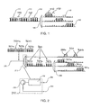
Ceci est illustré sur la figure 1 qui représente un démultiplexeur optique ordinaire 100 extrayant séparément trois bandes de longueurs d'ondes d'un multiplex constitué d'une suite de canaux répartis à intervalles réguliers dans le spectre :
- Une
bande 110 constituée de quatre canaux portés respectivement par un premier groupe de quatre longueurs d'onde. - Une bande 120 constituée de quatre canaux portés respectivement par un deuxième groupe de quatre longueurs d'onde.
- Une
bande 130 constituée de quatre canaux portés respectivement par un troisième groupe de quatre longueurs d'onde.
- A
strip 110 consisting of four channels carried respectively by a first group of four wavelengths. - A strip 120 consisting of four channels carried respectively by a second group of four wavelengths.
- A
strip 130 consisting of four channels carried respectively by a third group of four wavelengths.
Les bandes 110 et 120 sont séparées par une bande 139 correspondant à
deux canaux, mais qui n'est pas utilisée pour transmettre des signaux. Les bandes 120
et 130 sont séparées par une bande 140 correspondant à deux canaux, mais qui n'est
pas utilisée pour transmettre des signaux. En effet, si on utilise des équipements
ordinaires de démultiplexage de bandes, l'extraction des bandes 110, 120, 130 ne
peut pas être effectuée sans devoir sacrifier des canaux dits inter-bandes qui sont entre
les bandes 110 et 120, et entre les bandes 120 et 130. Ceci est dû à la grande
proximité des longueurs d'onde contiguës qui peuvent être transportées avec le mode
dit DWDM (impliquant des séparations spectrales entre canaux de 100 GHz, 50 GHz
voire 25 GHz), et aux limitations inhérentes au pouvoir de discrimination spectral
(appelé aussi sélectivité) des équipements ordinaires de démultiplexage de bandes, tel
que le démultiplexeur 100.The
Sur la figure 1, la bande passante du démultiplexeur ordinaire100 est illustrée
par un trapèze 150 ayant des cotés dont la pente n'est pas suffisamment raide. Cette
bande passante est assez large pour couvrir les canaux d'une bande de longueur
d'ondes (quatre canaux dans cet exemple) mais a une sélectivité insuffisante pour
éliminer efficacement les canaux inter-bandes constituant les bandes 139 et 140. Ces
canaux inter-bandes ne peuvent donc pas être utilisés, ce qui réduit de façon
significative les capacités de transport sur la fibre optique.In FIG. 1, the bandwidth of the ordinary demultiplexer100 is illustrated
by a
C'est pourquoi le but de l'invention est de fournir un système de démultiplexage optique permettant l'utilisation effective de ces longueurs d'ondes inter-bandes qui seraient autrement perdues.This is why the object of the invention is to provide a system of optical demultiplexing allowing the effective use of these wavelengths inter-bands that would otherwise be lost.
L'objet de l'invention est donc un système de démultiplexage optique permettant de séparer une bande unique faisant partie d'un premier peigne de bandes qui est entrelacé avec au moins un second peigne de bandes, chaque bande étant constituées d'une pluralité de canaux ayant des longueurs d'ondes adjacentes ; caractérisé en ce qu'il comprend :
- un premier étage de démultiplexage spectral pour extraire séparément chacun des peignes ;
- et un second étage de démultiplexage spectral pour extraire séparément chacune des bande constituant un peigne extrait par le ledit premier étage de filtrage.
- a first spectral demultiplexing stage for separately extracting each of the combs;
- and a second spectral demultiplexing stage for separately extracting each of the bands constituting a comb extracted by the said first filtering stage.
Le système selon l'invention permet d'utiliser tous les canaux et notamment les canaux appelés classiquement inter-bandes qu'on n'utilisait pas pour transmettre des signaux. Ces canaux deviennent utilisables notamment pour la gestion du réseau et des bandes de longueurs d'ondes, car le système selon l'invention permet d'obtenir une sélectivité suffisante, tout en ne comportant que des moyens simples et peu onéreux dans chacun des deux étages.The system according to the invention makes it possible to use all the channels and in particular the channels conventionally called inter-band that were not used to transmit signals. These channels become usable in particular for network management and wavelength bands, because the system according to the invention makes it possible to obtain sufficient selectivity, while comprising only simple means and few expensive in each of the two floors.
Les buts, objets, ainsi que les caractéristiques et avantages de l'invention
ressortiront mieux de la description détaillée d'un mode préféré de réalisation de cette
dernière. illustré par les dessins d'accompagnement dans lesquels :
Dans l'exemple de réalisation représenté sur la figure 2, un multiplex 200 arrive sur une fibre 205. Il est constitué de canaux répartis à intervalles réguliers. Il est constitué de deux peignes entrelacés :
- d'un premier peigne de bandes, 321, constitué de trois
bandes - et d'un second peigne de bandes, 320, constitué de deux
bandes
- un premier étage de démultiplexage spectral, à relativement faible bande passante et relativement grande sélectivité, ayant pour fonction principale d'extraire l'ensemble des canaux inter-bandes ;
- et un second étage de démultiplexage spectral, à relativement large bande passante et relativement faible sélectivité, pour séparer les bandes de longueurs d'onde restant après l'extraction de l'ensemble des canaux inter-bandes par le premier étage.
- a first strip comb, 321, consisting of three
strips - and a second comb of bands, 320, consisting of two
bands
- a first spectral demultiplexing stage, with relatively low bandwidth and relatively high selectivity, the main function of which is to extract all of the inter-band channels;
- and a second spectral demultiplexing stage, with relatively large bandwidth and relatively low selectivity, for separating the bands of wavelengths remaining after the extraction of all the inter-band channels by the first stage.
Le premier étage est constitué d'un désentrelaceur périodique de bandes, 210,
qui est destiné à séparer les deux peignes 320 et 321. Une première sortie du
démultiplexeur 210 fournit le peigne 320 (bandes 320a et 320b) qui comprend tous
les canaux inter-bandes. Ces canaux sont extraits mais restent multiplexés dans un
même multiplex, dans ce premier exemple. Les deux bandes 320a et 320b peuvent
être exploités pour transporter des signaux, mais pas séparément. Une seconde sortie
du désentrelaceur 210 fournit le peigne 321 qui comprend tous les canaux servant à
transporter l'information. Le désentrelaceur de bandes 210 est constitué de préférence
d'un filtre périodique (ou une cascade de filtres périodiques) ayant une sélectivité
suffisante pour atténuer efficacement les bandes 320a et 320b de canaux inter-bandes
dans le multiplex (comportant les bandes 321a, 321b, 321c) fourni sur la
seconde sortie.The first stage consists of a periodic strip deinterlacer, 210,
which is intended to separate the two
Le second étage est constitué par un démultiplexeur périodique de bandes,
240. Il comporte trois sorties fournissant séparément les bandes 213a, 321 b, 321 c. Le
démultiplexeur constituant le deuxième étage 240 peut être sans inconvénient un
démultiplexeur ordinaire de bandes de longueurs d'onde contiguës, à faible sélectivité
spectrale puisque les canaux inter-bandes (bandes 320a et 320b) ont été
préalablement extraits avec une grande sélectivité par le premier étage 210.The second stage consists of a periodic strip demultiplexer,
240. It has three
La réalisation du désentrelaceur de l'étage 210 fait appel à des techniques
connues de l'homme de l'art. Elle est cependant détaillée sur une partie agrandie de
la figure 2. Il comporte un circulateur 252 ayant une entrée reliée à la fibre 205, et
une première sortie reliée à un filtre optique périodique 254, par exemple un filtre dit
Fabry-Pérot. Le pouvoir de séparation spectrale du filtre 254 doit être suffisant pour
permettre l'extraction des bandes 320a, 320b de canaux inter-bandes. Ces bandes
apparaissent sur la sortie 256 du filtre périodique 254. Une seconde sortie 258 du
circulateur 252 constitue la seconde sortie du désentrelaceur 210, fournissant les
bandes 321a, 321b, 321c. Il est à noter que le circulateur 252 étant un composant
coûteux, on peut avantageusement le remplacer par un isolateur suivi d'un simple
coupleur.The production of the deinterlacer on
La figure 3 reprend pour l'essentiel le contenu de la figure 2. Elle représente
un système de démultiplexage pour le cas où les deux bandes de canaux inter-bandes,
320a et 320b, sont exploitées séparément. En plus des moyens du premier
exemple de réalisation représenté sur la figure 2, ce second exemple de réalisation
comporte un démultiplexeur périodique de bandes, 360, ayant une entrée reliée à la
première sortie du désentrelaceur 210, et ayant deux sorties pour extraire séparément
les bandes 320a et 320b qui sont utilisées elles aussi pour transporter des signaux. FIG. 3 essentially repeats the content of FIG. 2. It represents a demultiplexing system for the case where the two bands of inter-band channels, 320a and 320b, are used separately. In addition to the means of the first embodiment shown in Figure 2, this second embodiment includes a periodic strip demultiplexer, 360, having an input connected to the first output of the
De préférence chacun des démultiplexeur périodiques de bandes, 240 et 360, comprend un filtre périodique constitué de dépôts en couches minces.Preferably each of the periodic band demultiplexers, 240 and 360, includes a periodic filter consisting of deposits in thin layers.
Ainsi, l'invention permet que les canaux inter-bandes puissent être réutilisés alors qu'ils étaient habituellement inexploitables. Dans un mode préféré de réalisation de l'invention, ces canaux sont employés au contrôle du réseau lui-même transportant toutes les informations nécessaires à son bon fonctionnement et pour le maintenir à son niveau optimum de performance. Dans un mode de transport DWDM, basé sur les techniques de mélange de nombreuses longueurs d'ondes sur des fibres optiques interconnectant des stations OADM où des bandes de longueurs d'ondes doivent être dérivées localement et d'autres ajoutées, une gestion rigoureuse s'impose pour une utilisation efficace de celles-ci. Cette gestion nécessite un canal ou des canaux de contrôle qui utilisent avantageusement les longueurs d'ondes inter-bandes réutilisables par la mise en oeuvre de l'invention.Thus, the invention allows that the inter-band channels can be reused when they were usually unusable. In a preferred embodiment of the invention, these channels are used to control the network itself carrying all the information necessary for its proper functioning and to keep it at its optimum level of performance. In a DWDM transport mode, based on techniques for mixing many wavelengths on optical fibers interconnecting OADM stations where wavelength bands are to be locally derived and others added, rigorous management is essential for effective use of these. This management requires a channel or channels of controls that advantageously use reusable inter-band wavelengths by implementing the invention.
Enfin on notera que le nombre de canaux inter-bandes, qui est toujours montré comme étant de deux dans les figures 1 à 3 utilisées pour décrire l'art antérieur et l'invention, peut évidemment être différent de ce nombre et qu'il ne s'agit que d'un exemple particulier. Notamment, dans une mise en oeuvre préférée de l'invention on pourra limiter à un seul canal inter-bandes par le choix d'un démultiplexeur de bandes, 240, qui l'autorise parce que suffisamment sélectif, ou parce que le choix des longueurs d'ondes le permet en raison d'un espacement spectral suffisant. On peut alors obtenir une correspondance un pour un entre une bande de longueurs d'onde et l'un ou l'autre des canaux inter-bandes contiguës, qui peut être utilisé pour son contrôle.Finally we note that the number of inter-band channels, which is always shown as being two in Figures 1 to 3 used to describe the prior art and the invention, can obviously be different from this number and that it is only a particular example. In particular, in a preferred implementation of the invention, may limit to a single inter-band channel by choosing a demultiplexer bands, 240, which authorizes it because it is sufficiently selective, or because the choice of wavelengths allow this due to sufficient spectral spacing. We can then get a one-for-one match between a wavelength band and either of the contiguous inter-band channels, which can be used for sound control.
Claims (3)
Applications Claiming Priority (4)
| Application Number | Priority Date | Filing Date | Title |
|---|---|---|---|
| FR0112448 | 2001-09-27 | ||
| FR0112448A FR2830144A1 (en) | 2001-09-27 | 2001-09-27 | Internet demultiplexing high wavelength number fibre optic transmission having low pass band/high selectivity filtering extracting without loss interband channels and second stage wide pass band low selectivity. |
| FR0113102A FR2830145B1 (en) | 2001-09-27 | 2001-10-11 | OPTICAL DEMULTIPLEXING SYSTEM OF WAVELENGTH BANDS |
| FR0113102 | 2001-10-11 |
Publications (1)
| Publication Number | Publication Date |
|---|---|
| EP1300975A1 true EP1300975A1 (en) | 2003-04-09 |
Family
ID=26213198
Family Applications (1)
| Application Number | Title | Priority Date | Filing Date |
|---|---|---|---|
| EP02292364A Withdrawn EP1300975A1 (en) | 2001-09-27 | 2002-09-26 | Optical demultiplexing system for wavelength bands |
Country Status (6)
| Country | Link |
|---|---|
| US (1) | US7085447B2 (en) |
| EP (1) | EP1300975A1 (en) |
| JP (1) | JP2005504478A (en) |
| CN (1) | CN1301602C (en) |
| FR (1) | FR2830145B1 (en) |
| WO (1) | WO2003028263A1 (en) |
Families Citing this family (13)
| Publication number | Priority date | Publication date | Assignee | Title |
|---|---|---|---|---|
| US8271279B2 (en) | 2003-02-21 | 2012-09-18 | Qnx Software Systems Limited | Signature noise removal |
| US8326621B2 (en) | 2003-02-21 | 2012-12-04 | Qnx Software Systems Limited | Repetitive transient noise removal |
| US7885420B2 (en) | 2003-02-21 | 2011-02-08 | Qnx Software Systems Co. | Wind noise suppression system |
| US8073689B2 (en) * | 2003-02-21 | 2011-12-06 | Qnx Software Systems Co. | Repetitive transient noise removal |
| US7949522B2 (en) | 2003-02-21 | 2011-05-24 | Qnx Software Systems Co. | System for suppressing rain noise |
| US7725315B2 (en) * | 2003-02-21 | 2010-05-25 | Qnx Software Systems (Wavemakers), Inc. | Minimization of transient noises in a voice signal |
| US7895036B2 (en) * | 2003-02-21 | 2011-02-22 | Qnx Software Systems Co. | System for suppressing wind noise |
| CN1866808B (en) * | 2005-05-21 | 2010-04-28 | 华为技术有限公司 | Multiplex/demultiplex method and apparatus for wavelength-division multiplex system |
| CN100549741C (en) * | 2006-08-21 | 2009-10-14 | 中兴通讯股份有限公司 | A kind of packet filtering device of non-black wavelength and packet filtering method thereof |
| JP2008259129A (en) * | 2007-04-09 | 2008-10-23 | Nippon Telegr & Teleph Corp <Ntt> | Optical network system using optical cross-connect apparatus |
| JP2008259134A (en) * | 2007-04-09 | 2008-10-23 | Nippon Telegr & Teleph Corp <Ntt> | Wavelength selection switch, optical cross-connect device, wavelength selecting method, and signal control method in optical cross-connect device |
| JP2008259132A (en) * | 2007-04-09 | 2008-10-23 | Nippon Telegr & Teleph Corp <Ntt> | Optical cross-connect system and signal control method of optical cross-connect system |
| US20100260500A1 (en) * | 2009-04-08 | 2010-10-14 | Nec Laboratories America Inc | Mult9-degree wavelength cross-connect using bidirectional wavelength selective switch |
Citations (7)
| Publication number | Priority date | Publication date | Assignee | Title |
|---|---|---|---|---|
| EP0874489A2 (en) * | 1997-04-25 | 1998-10-28 | Jds Fitel Inc. | Method and circuit for demultiplexing an optical signal |
| US6067178A (en) * | 1997-09-16 | 2000-05-23 | Oplink Communications, Inc. | Multiple wavelength division multiplexer with reduced loss |
| EP1043859A2 (en) * | 1999-04-05 | 2000-10-11 | Kabushiki Kaisha Toshiba | Optical add/drop multiplexer node device |
| WO2001005082A1 (en) * | 1999-07-13 | 2001-01-18 | Jds Uniphase Corporation | Method and devices for multiplexing and de-multiplexing multiple wavelengths |
| WO2001016558A1 (en) * | 1999-09-01 | 2001-03-08 | Avanex Corporation | Dense wavelength division multiplexer utilizing an asymmetric pass band interferometer |
| US6208444B1 (en) * | 1996-10-29 | 2001-03-27 | Chorum Technologies Inc. | Apparatus for wavelength demultiplexing using a multi-cavity etalon |
| WO2001041347A1 (en) * | 1999-11-30 | 2001-06-07 | Corning Incorporated | Narrow band wavelength division multiplexer and method of multiplexing optical signals |
Family Cites Families (2)
| Publication number | Priority date | Publication date | Assignee | Title |
|---|---|---|---|---|
| CA2203729C (en) * | 1997-04-25 | 2001-04-17 | Jds Fitel Inc. | Method and circuit for demultiplexing an optical signal |
| FR2818080B1 (en) * | 2000-12-07 | 2003-03-28 | Cit Alcatel | DEMULTIPLEXING / MULTIPLEXING SYSTEM IN INTERLEAVED BANDS |
-
2001
- 2001-10-11 FR FR0113102A patent/FR2830145B1/en not_active Expired - Lifetime
-
2002
- 2002-09-26 US US10/491,147 patent/US7085447B2/en not_active Expired - Lifetime
- 2002-09-26 WO PCT/FR2002/003280 patent/WO2003028263A1/en active Application Filing
- 2002-09-26 JP JP2003531653A patent/JP2005504478A/en active Pending
- 2002-09-26 EP EP02292364A patent/EP1300975A1/en not_active Withdrawn
- 2002-09-26 CN CNB028214072A patent/CN1301602C/en not_active Expired - Fee Related
Patent Citations (7)
| Publication number | Priority date | Publication date | Assignee | Title |
|---|---|---|---|---|
| US6208444B1 (en) * | 1996-10-29 | 2001-03-27 | Chorum Technologies Inc. | Apparatus for wavelength demultiplexing using a multi-cavity etalon |
| EP0874489A2 (en) * | 1997-04-25 | 1998-10-28 | Jds Fitel Inc. | Method and circuit for demultiplexing an optical signal |
| US6067178A (en) * | 1997-09-16 | 2000-05-23 | Oplink Communications, Inc. | Multiple wavelength division multiplexer with reduced loss |
| EP1043859A2 (en) * | 1999-04-05 | 2000-10-11 | Kabushiki Kaisha Toshiba | Optical add/drop multiplexer node device |
| WO2001005082A1 (en) * | 1999-07-13 | 2001-01-18 | Jds Uniphase Corporation | Method and devices for multiplexing and de-multiplexing multiple wavelengths |
| WO2001016558A1 (en) * | 1999-09-01 | 2001-03-08 | Avanex Corporation | Dense wavelength division multiplexer utilizing an asymmetric pass band interferometer |
| WO2001041347A1 (en) * | 1999-11-30 | 2001-06-07 | Corning Incorporated | Narrow band wavelength division multiplexer and method of multiplexing optical signals |
Also Published As
| Publication number | Publication date |
|---|---|
| CN1579061A (en) | 2005-02-09 |
| US20050238283A1 (en) | 2005-10-27 |
| CN1301602C (en) | 2007-02-21 |
| JP2005504478A (en) | 2005-02-10 |
| FR2830145A1 (en) | 2003-03-28 |
| FR2830145B1 (en) | 2004-04-16 |
| WO2003028263A1 (en) | 2003-04-03 |
| US7085447B2 (en) | 2006-08-01 |
Similar Documents
| Publication | Publication Date | Title |
|---|---|---|
| EP0677936B1 (en) | Reconfigurable multiwavelength optical ring network | |
| FR2738432A1 (en) | OPTICAL COMPONENT SUITABLE FOR MONITORING A WAVELENGTH MULTILENGTH LINKAGE AND INSERT-EXTRACTION MULTIPLEXER USING THE SAME, APPLICATION TO OPTICAL NETWORKS | |
| EP0730173A1 (en) | Optical drop- and insert multiplexer with high isolation | |
| EP1300975A1 (en) | Optical demultiplexing system for wavelength bands | |
| EP0838918B1 (en) | Device for add-dropping wavelength multiplexed channels | |
| JP2000115134A (en) | Scalable optical demultiplexing device for wide band high density wavelength division multiplexing system | |
| US20020135838A1 (en) | Dynamic wavelength add/drop multiplexer for UDWDM optical communication system | |
| JP4002063B2 (en) | Optical wavelength add / drop multiplexer and filter element used therefor | |
| EP0677935A1 (en) | Ring network architecture for multiple access transmission by means of spectral routing | |
| EP1248336A2 (en) | Method and apparatus for wavelength conversion | |
| FR2762170A1 (en) | Optical amplification device for repeater in WDM communication system | |
| EP1179964A2 (en) | Optical signal switch | |
| EP1213866B1 (en) | Interleaved bands demultiplexing/multiplexing system | |
| EP1657840B1 (en) | DWDM communication network with periodic wavelenght multiplexing | |
| EP0697800A1 (en) | Optical crossconnect | |
| FR2829327A1 (en) | NETWORK IN RING REALIZED FROM A DUAL OPTICAL BUS | |
| EP1398896A1 (en) | Frequency comb for optical frequency division multiplexing network | |
| EP1355441A1 (en) | Method and apparatus for controlling the transmission of optical signals | |
| EP1315320A2 (en) | Optical fibre transmission system with common clock | |
| EP1303161A1 (en) | Frequency selective switch and reconfigurable optical delay circuit containing the same | |
| FR2736480A1 (en) | COLORING DEVICE FOR OPTICAL SIGNALS | |
| EP2160045B1 (en) | Optical packet communication node | |
| FR2830144A1 (en) | Internet demultiplexing high wavelength number fibre optic transmission having low pass band/high selectivity filtering extracting without loss interband channels and second stage wide pass band low selectivity. | |
| FR3027174A1 (en) | OPTOELECTRONIC WDM CASCADE TRANSMITTER-TRANSCEIVER DEVICE, SYSTEM, AND METHOD | |
| WO2001078282A1 (en) | Wavelength multiplexing optical fibre transmission device |
Legal Events
| Date | Code | Title | Description |
|---|---|---|---|
| PUAI | Public reference made under article 153(3) epc to a published international application that has entered the european phase |
Free format text: ORIGINAL CODE: 0009012 |
|
| AK | Designated contracting states |
Kind code of ref document: A1 Designated state(s): AT BE BG CH CY CZ DE DK EE ES FI FR GB GR IE IT LI LU MC NL PT SE SK TR Designated state(s): AT BE BG CH CY CZ DE DK EE ES FI FR GB GR IE IT LI LU MC NL PT SE SK TR |
|
| AX | Request for extension of the european patent |
Extension state: AL LT LV MK RO SI |
|
| RIN1 | Information on inventor provided before grant (corrected) |
Inventor name: LE SAUZE, NICOLAS Inventor name: BISSON, ARNAUD Inventor name: FAURE, JEAN-PAUL |
|
| 17P | Request for examination filed |
Effective date: 20031009 |
|
| AKX | Designation fees paid |
Designated state(s): AT BE BG CH CY CZ DE DK EE ES FI FR GB GR IE IT LI LU MC NL PT SE SK TR |
|
| 17Q | First examination report despatched |
Effective date: 20040525 |
|
| STAA | Information on the status of an ep patent application or granted ep patent |
Free format text: STATUS: THE APPLICATION IS DEEMED TO BE WITHDRAWN |
|
| 18D | Application deemed to be withdrawn |
Effective date: 20051012 |